EP3385553A1 - Foil bearing - Google Patents
Foil bearing Download PDFInfo
- Publication number
- EP3385553A1 EP3385553A1 EP16870439.3A EP16870439A EP3385553A1 EP 3385553 A1 EP3385553 A1 EP 3385553A1 EP 16870439 A EP16870439 A EP 16870439A EP 3385553 A1 EP3385553 A1 EP 3385553A1
- Authority
- EP
- European Patent Office
- Prior art keywords
- foil
- projecting portions
- bearing
- projecting
- shaft
- Prior art date
- Legal status (The legal status is an assumption and is not a legal conclusion. Google has not performed a legal analysis and makes no representation as to the accuracy of the status listed.)
- Withdrawn
Links
- 239000011888 foil Substances 0.000 title claims abstract description 320
- 239000012530 fluid Substances 0.000 claims description 10
- 239000007789 gas Substances 0.000 description 19
- 230000006835 compression Effects 0.000 description 14
- 238000007906 compression Methods 0.000 description 14
- 230000002093 peripheral effect Effects 0.000 description 13
- 230000000694 effects Effects 0.000 description 9
- 238000003780 insertion Methods 0.000 description 5
- 230000037431 insertion Effects 0.000 description 5
- 239000000463 material Substances 0.000 description 5
- 239000002184 metal Substances 0.000 description 4
- 229910052751 metal Inorganic materials 0.000 description 4
- 229910001369 Brass Inorganic materials 0.000 description 3
- 229910000831 Steel Inorganic materials 0.000 description 3
- 230000015572 biosynthetic process Effects 0.000 description 3
- 239000010951 brass Substances 0.000 description 3
- 230000002708 enhancing effect Effects 0.000 description 3
- 238000007667 floating Methods 0.000 description 3
- 239000010959 steel Substances 0.000 description 3
- 229910000975 Carbon steel Inorganic materials 0.000 description 2
- 229910000881 Cu alloy Inorganic materials 0.000 description 2
- 239000010962 carbon steel Substances 0.000 description 2
- 238000002485 combustion reaction Methods 0.000 description 2
- 238000010168 coupling process Methods 0.000 description 2
- 230000007423 decrease Effects 0.000 description 2
- 230000005489 elastic deformation Effects 0.000 description 2
- 239000000446 fuel Substances 0.000 description 2
- 239000003921 oil Substances 0.000 description 2
- 230000001105 regulatory effect Effects 0.000 description 2
- 229910000906 Bronze Inorganic materials 0.000 description 1
- 241000252203 Clupea harengus Species 0.000 description 1
- 238000005452 bending Methods 0.000 description 1
- 210000000988 bone and bone Anatomy 0.000 description 1
- 239000010974 bronze Substances 0.000 description 1
- 230000001276 controlling effect Effects 0.000 description 1
- KUNSUQLRTQLHQQ-UHFFFAOYSA-N copper tin Chemical compound [Cu].[Sn] KUNSUQLRTQLHQQ-UHFFFAOYSA-N 0.000 description 1
- 230000007797 corrosion Effects 0.000 description 1
- 238000005260 corrosion Methods 0.000 description 1
- 230000008878 coupling Effects 0.000 description 1
- 238000005859 coupling reaction Methods 0.000 description 1
- 230000007547 defect Effects 0.000 description 1
- 230000003111 delayed effect Effects 0.000 description 1
- 238000006073 displacement reaction Methods 0.000 description 1
- 230000001747 exhibiting effect Effects 0.000 description 1
- 230000012447 hatching Effects 0.000 description 1
- 235000019514 herring Nutrition 0.000 description 1
- 230000001771 impaired effect Effects 0.000 description 1
- JEIPFZHSYJVQDO-UHFFFAOYSA-N iron(III) oxide Inorganic materials O=[Fe]O[Fe]=O JEIPFZHSYJVQDO-UHFFFAOYSA-N 0.000 description 1
- 239000007788 liquid Substances 0.000 description 1
- 239000010687 lubricating oil Substances 0.000 description 1
- 238000003754 machining Methods 0.000 description 1
- 238000000034 method Methods 0.000 description 1
- 239000000203 mixture Substances 0.000 description 1
- 238000005457 optimization Methods 0.000 description 1
- 239000010935 stainless steel Substances 0.000 description 1
- 229910001220 stainless steel Inorganic materials 0.000 description 1
- 239000002918 waste heat Substances 0.000 description 1
- XLYOFNOQVPJJNP-UHFFFAOYSA-N water Substances O XLYOFNOQVPJJNP-UHFFFAOYSA-N 0.000 description 1
Images



Classifications
-
- F—MECHANICAL ENGINEERING; LIGHTING; HEATING; WEAPONS; BLASTING
- F16—ENGINEERING ELEMENTS AND UNITS; GENERAL MEASURES FOR PRODUCING AND MAINTAINING EFFECTIVE FUNCTIONING OF MACHINES OR INSTALLATIONS; THERMAL INSULATION IN GENERAL
- F16C—SHAFTS; FLEXIBLE SHAFTS; ELEMENTS OR CRANKSHAFT MECHANISMS; ROTARY BODIES OTHER THAN GEARING ELEMENTS; BEARINGS
- F16C17/00—Sliding-contact bearings for exclusively rotary movement
- F16C17/02—Sliding-contact bearings for exclusively rotary movement for radial load only
- F16C17/024—Sliding-contact bearings for exclusively rotary movement for radial load only with flexible leaves to create hydrodynamic wedge, e.g. radial foil bearings
-
- F—MECHANICAL ENGINEERING; LIGHTING; HEATING; WEAPONS; BLASTING
- F01—MACHINES OR ENGINES IN GENERAL; ENGINE PLANTS IN GENERAL; STEAM ENGINES
- F01D—NON-POSITIVE DISPLACEMENT MACHINES OR ENGINES, e.g. STEAM TURBINES
- F01D25/00—Component parts, details, or accessories, not provided for in, or of interest apart from, other groups
- F01D25/16—Arrangement of bearings; Supporting or mounting bearings in casings
- F01D25/162—Bearing supports
- F01D25/164—Flexible supports; Vibration damping means associated with the bearing
-
- F—MECHANICAL ENGINEERING; LIGHTING; HEATING; WEAPONS; BLASTING
- F01—MACHINES OR ENGINES IN GENERAL; ENGINE PLANTS IN GENERAL; STEAM ENGINES
- F01D—NON-POSITIVE DISPLACEMENT MACHINES OR ENGINES, e.g. STEAM TURBINES
- F01D25/00—Component parts, details, or accessories, not provided for in, or of interest apart from, other groups
- F01D25/16—Arrangement of bearings; Supporting or mounting bearings in casings
- F01D25/166—Sliding contact bearing
- F01D25/168—Sliding contact bearing for axial load mainly
-
- F—MECHANICAL ENGINEERING; LIGHTING; HEATING; WEAPONS; BLASTING
- F16—ENGINEERING ELEMENTS AND UNITS; GENERAL MEASURES FOR PRODUCING AND MAINTAINING EFFECTIVE FUNCTIONING OF MACHINES OR INSTALLATIONS; THERMAL INSULATION IN GENERAL
- F16C—SHAFTS; FLEXIBLE SHAFTS; ELEMENTS OR CRANKSHAFT MECHANISMS; ROTARY BODIES OTHER THAN GEARING ELEMENTS; BEARINGS
- F16C27/00—Elastic or yielding bearings or bearing supports, for exclusively rotary movement
- F16C27/02—Sliding-contact bearings
-
- F—MECHANICAL ENGINEERING; LIGHTING; HEATING; WEAPONS; BLASTING
- F16—ENGINEERING ELEMENTS AND UNITS; GENERAL MEASURES FOR PRODUCING AND MAINTAINING EFFECTIVE FUNCTIONING OF MACHINES OR INSTALLATIONS; THERMAL INSULATION IN GENERAL
- F16C—SHAFTS; FLEXIBLE SHAFTS; ELEMENTS OR CRANKSHAFT MECHANISMS; ROTARY BODIES OTHER THAN GEARING ELEMENTS; BEARINGS
- F16C43/00—Assembling bearings
- F16C43/02—Assembling sliding-contact bearings
-
- F—MECHANICAL ENGINEERING; LIGHTING; HEATING; WEAPONS; BLASTING
- F16—ENGINEERING ELEMENTS AND UNITS; GENERAL MEASURES FOR PRODUCING AND MAINTAINING EFFECTIVE FUNCTIONING OF MACHINES OR INSTALLATIONS; THERMAL INSULATION IN GENERAL
- F16C—SHAFTS; FLEXIBLE SHAFTS; ELEMENTS OR CRANKSHAFT MECHANISMS; ROTARY BODIES OTHER THAN GEARING ELEMENTS; BEARINGS
- F16C2360/00—Engines or pumps
- F16C2360/23—Gas turbine engines
Definitions
- the first projecting portions, the second projecting portions, or both the first projecting portions and the second projecting portions comprise large projecting portions each having a large projection amount from the intermediate portion and small projecting portions each having a small projection amount from the intermediate portion, non-linearity is given to the resiliency characteristics of the back foil portion. Therefore, the resiliency characteristics of the back foil portion can be diversified.
- the intermediate portion When the intermediate portion has an opening portion, the intermediate portion becomes more pliable, thereby being capable of reducing the rigidity of the back foil portion.
- the foil 12 comprises a first region 12a on the rotation direction R side of the shaft 6 and a second region 12b on the side opposite to the rotation direction side.
- one foil 12 of the two assembled foils 12 is colored gray.
- minute slits 12a3 are formed in the top foil portion Tf to reduce the rigidity of the top foil portion Tf. Therefore, when the top foil portion Tf is deformed along the cutout portion 12b2, the deformation is smooth.
- the rigidity of the bearing surface X can be partially controlled through variation in distribution density of the first projecting portions 21 and the second projecting portions 22.
- a support span S (see FIG. 11 ) between adjacent projecting portions 21 and 22 is reduced.
- the rigidity in this region can be increased.
- the rigidity in this region can be reduced.
Landscapes
- Engineering & Computer Science (AREA)
- General Engineering & Computer Science (AREA)
- Mechanical Engineering (AREA)
- Physics & Mathematics (AREA)
- Fluid Mechanics (AREA)
- Support Of The Bearing (AREA)
Abstract
Description
- The present invention relates to a foil bearing.
- There has been known a foil bearing as a bearing which is less liable to cause a whirl and enables management of a gap width of a bearing gap to be performed easily even under an environment in which a temperature change is large . The foil bearing has a bearing surface formed of flexible metal thin plates (foils) having a low rigidity with respect to bending, and is configured to support a load by allowing flexure of the bearing surface. Such a configuration of the foil bearing enables automatic adjustment of a bearing gap to an appropriate width in accordance with, for example, an operation condition. For example, in
Patent Literature 1 described below, there is disclosed a foil bearing of a so-called bump type as an example of a radial foil bearing configured to support a radial load. - Patent Literature 1:
JP 2013-87789 A - The foil bearing described in
Patent Literature 1 includes a cylindrical top foil, back foils (bump foils) configured to elastically support the top foil, and a bearing holder to which the top foil and the back foils are mounted. In this bump-type foil bearing, the back foils are elastically deformed when the top foil receives a load, thereby allowing flexure of the top foil. - Incidentally, as illustrated in
FIG. 23 , the back foils of the bump-type foil bearing each have a corrugated plate shape in which protrudingportions 200 extending in an axial direction (arrow direction) are arrayed in a circumferential direction. When the back foils are elastically deformed, the back foils are deformed through stretching of each protrudingportion 200. However, the deformation resistance given at the time of deformation is large, and the back foils as a whole have a high rigidity, with the result that the top foil tends to be poor in pliability. When the top foil is poor in pliability, the automatic adjustment function for the bearing gap is impaired, which may result in defects such as being liable to cause contact between a shaft and the top foil. - Therefore, the present invention has an object to provide a foil bearing in which a top foil portion is enhanced in pliability.
- The present invention has been made in order to solve the above-mentioned problem, and according to one embodiment of the present invention, there is provided a foil bearing, comprising: a top foil portion having a bearing surface opposed to a shaft to be supported; and a back foil portion, which is arranged on a back of the top foil portion, and is configured to elastically support the top foil portion, wherein the foil bearing is configured to support relative rotation of a shaft in a non-contact state with a fluid film generated in a bearing gap between the shaft and the bearing surface, wherein the back foil portion comprises: an intermediate portion being flat; first projecting portions projecting on a front side of the intermediate portion; and second projecting portions projecting on a back side of the intermediate portion.
- With this configuration, fluid pressure generated in the bearing gap during an operation of the bearing causes a compression force in an action direction of the fluid pressure (corresponding to a radial direction in a radial bearing, and an axial direction in a thrust bearing) to act on the back foil portion through the top foil portion. The intermediate portion of the back foil portion is low in rigidity with respect to the compression force. Therefore, when the compression force is applied to the back foil portion, the intermediate portion first deforms to absorb the compression force. Thus, as compared to a back foil portion of an existing bump-type foil bearing having no such flat portion, the rigidity of the back foil portion as a whole is reduced, thereby being capable of enhancing the pliability of the bearing surface.
- It is preferred that the first projecting portions and the second projecting portions be arrayed intermittently at least in a relative rotation direction of the shaft and in a direction orthogonal to the relative rotation direction along the bearing surface. With this configuration, when the back foil portion is deformed, relative movement is allowed between the adjacent projecting portions of the same kind in the two directions. Therefore, the pliability of the bearing surface can further be enhanced.
- When the back foil portion comprises a high-density region in which the first projecting portions and the second projecting portions are densely distributed and a low-density region in which the first projecting portions and the second projecting portions are sparsely distributed, the rigidity at parts of the back foil portion as well as the rigidity at parts of the bearing surface can be controlled.
- When the first projecting portions, the second projecting portions, or both the first projecting portions and the second projecting portions comprise large projecting portions each having a large projection amount from the intermediate portion and small projecting portions each having a small projection amount from the intermediate portion, non-linearity is given to the resiliency characteristics of the back foil portion. Therefore, the resiliency characteristics of the back foil portion can be diversified.
- When the intermediate portion has an opening portion, the intermediate portion becomes more pliable, thereby being capable of reducing the rigidity of the back foil portion.
- When the back foil portion has a maximum rigidity at a position corresponding to a maximum pressure generating portion in the bearing gap, the bearing surface also has a maximum rigidity at the maximum pressure generating portion. Therefore, an escape of the fluid caused by the deformation of the bearing surface can be prevented, thereby being capable of stably maintaining a floating force on the shaft.
- As described above, according to the present invention, the pliability of the top foil portion can be enhanced. With this, the automatic adjustment function for the bearing gap can suitably be exerted, thereby being capable of reliably preventing the contact between the shaft and the top foil portion.
-
-
FIG. 1 is a view for illustrating a schematic configuration of a micro gas turbine. -
FIG. 2 is a view for illustrating a schematic configuration of a rotor support structure in the micro gas turbine. -
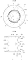
FIG. 3 is a sectional view for illustrating a foil bearing according to an embodiment of the present invention. -
FIG. 4 is a plan view of a foil. -
FIG. 5 is a plan view of two foils coupled to each other as seen from a back surface side. -
FIG. 6 is a perspective view for illustrating a state in which three foils are temporarily assembled. -
FIG. 7 is a perspective view for illustrating a state of mounting the temporarily assembled body of the foils to a foil holder. -
FIG. 8 is an enlarged sectional view for illustrating a foil overlapping portion of the foil bearing. -
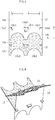
FIG. 9 is a perspective view of a projection-and-recess foil portion. -
FIG. 10 is a sectional view of the projection-and-recess foil portion. -
FIG. 11 is an enlarged sectional view of the foil bearing illustrated inFIG. 3 in a developed state. -
FIG. 12 isa plan view of a foil having the proj ection-and-recess foil portion. -
FIG. 13 is a plan view of the projection-and-recess foil portion. -
FIG. 14 is a plan view of the foil having the projection-and-recess foil portion. -
FIG. 15 is a sectional view of the foil bearing illustrated inFIG. 3 in a developed state. -
FIG. 16 is a sectional view taken along the line B-B inFIG. 14 . -
FIG. 17 is a sectional view for illustrating a projection-and-recess foil member in another embodiment of the present invention. -
FIG. 18 is a perspective view for illustrating a projection-and-recess foil member in another embodiment of the present invention. -
FIG. 19 is a sectional view for illustrating a radial foil bearing of a leaf type. -
FIG. 20 is a sectional view for illustrating a radial foil bearing of a bump type. -
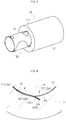
FIG. 21 is a perspective view for illustrating a thrust foil bearing of a leaf type. -
FIG. 22 is a sectional view taken along the line D-D inFIG. 21 . -
FIG. 23 is a perspective view for illustrating a back foil of a bump-type foil bearing. - Now, description is made of embodiments of the present invention with reference to the drawings.
- In
FIG. 1 , a configuration of a gas turbine device which is called a "micro gas turbine" is conceptually illustrated as one example of a turbo-machine. This gas turbine device comprises, as a main configuration, aturbine 1 forming a blade cascade, acompressor 2, apower generator 3, acombustor 4, and aregenerator 5. Theturbine 1 and thecompressor 2 are mounted to ashaft 6 extending in a horizontal direction to construct a rotor on a rotary side together with theshaft 6. One end of theshaft 6 in an axial direction thereof is coupled to thepower generator 3. When this micro gas turbine is operated, air is taken in through anintake port 7. The taken-in air is compressed by thecompressor 2 and heated by theregenerator 5, and thereafter sent to thecombustor 4. Thecombustor 4 mixes fuel into the compressed and heated air and combusts mixture of fuel and the air, to thereby generate high-temperature and high-pressure gas and rotate theturbine 1 with this gas. When theturbine 1 is rotated, a rotary force thereof is transmitted to thepower generator 3 through theshaft 6, to thereby drive thepower generator 3 to rotate. Power generated by driving thepower generator 3 to rotate is output through aninverter 8. Temperature of the gas after the rotation of theturbine 1 is relatively high. Thus, the gas is delivered to theregenerator 5 to perform heat exchange with compressed gas before combustion, thereby reusing the heat of the gas after combustion. The gas after completion of the heat exchange in theregenerator 5 passes through a wasteheat collecting device 9, and is then discharged as exhaust gas. - In
FIG. 2 , one example of a support structure for the rotor in the micro gas turbine illustrated inFIG. 1 is conceptually illustrated. In this support structure,radial bearings 10 are arranged near theshaft 6, and thrustbearings 30 are arranged on both sides of aflange portion 6b in an axial direction thereof, theflange portion 6b being arranged on theshaft 6. Theshaft 6 is supported by theseradial bearings 10 andthrust bearings 30 rotatably in both the radial direction and the thrust direction. In this support structure, a region between theturbine 1 and thecompressor 2 has a high-temperature atmosphere because the region is adjacent to theturbine 1, which is rotated by the high-temperature and high-pressure gas. In addition, theshaft 6 is rotated at a rotation speed of several ten thousand rpm or higher. Therefore, as thebearings - As an example of a foil bearing which is suitable for the
radial bearing 10 to be used for the above-mentioned micro gas turbine, a foil bearing of a so-called multi-arc type is used. Now, description is made of a basic configuration of the multi-arc type foil bearing with reference toFIG. 3 to FIG. 8 . - As illustrated in
FIG. 3 , the multi-arc type radial foil bearing 10 comprises afoil holder 11 and foils 12. Thefoil holder 11 has an innerperipheral surface 11a having a cylindrical surface shape. The foils 12 are arranged at a plurality of positions in a rotation direction of theshaft 6 on the innerperipheral surface 11a of thefoil holder 11. The foil bearing 10 of the illustrated example is an example in which thefoils 12 are arranged at three positions on the innerperipheral surface 11a. Theshaft 6 is inserted on a radially inner side of thefoils 12. - The
foil holder 11 may be made of metal (for example, steel material) such as sintered metal or ingot material. At a plurality of positions (the same number as the number of foils) apart from each other in a rotation direction R in the innerperipheral surface 11a of thefoil holder 11, there are formedaxial grooves 11b serving as mounting portions for thefoils 12. - Foil members forming the
foils 12 are each formed by processing a band-shaped foil having a thickness of from about 20 µm to about 200 µm, which is made of metal having sufficient resiliency and exhibiting high processability such as steel material or copper alloy, into a predetermined shape, for example, by press working. As a representative example of steel material or copper alloy, carbon steel or brass may be given. However, with the general carbon steel, a rust-prevention effect with oil cannot be expected due to absence of lubricating oil in the atmosphere, with the result that corrosion caused by rust is liable to occur. Further, with the brass, there is a case in which delayed crack is formed due to machining strain (as the amount of Zn contained in the brass is larger, such tendency becomes more conspicuous). Therefore, it is preferred that a band-shaped foil made of stainless steel or bronze be used. - As illustrated in
FIG. 4 , thefoil 12 comprises afirst region 12a on the rotation direction R side of theshaft 6 and asecond region 12b on the side opposite to the rotation direction side. - The
first region 12a comprises a top foil portion Tf and protruding portions 12a2. The top foil portion Tf forms a bearing surface X. The protruding portions 12a2 are formed at a plurality of positions in a direction N extending along a surface of the top foil portion Tf and being orthogonal to the rotation direction R (hereinafter simply referred to as "orthogonal direction N"), and protrude toward the rotation direction R side. In this embodiment, illustration is given of the case in which the protruding portions 12a2 are formed at three positions along the orthogonal direction. At base end portions of the protruding portions 12a2, there are formed minute slits 12a3 extending from foil edge portions in a direction opposite to the rotation direction. - At a
rear end 12d (end portion on the side opposite to the rotation direction side) of thesecond region 12b, there are formed two cutout portions 12b2, which are arranged apart in the orthogonal direction N and are recessed in the rotation direction R. A width dimension of each cutout portion 12b2 in the orthogonal direction N gradually decreases toward the rotation direction R. In this embodiment, illustration is given of the case in which each cutout portion 12b2 is entirely formed into an arc shape. However, each cutout portion 12b2 may be formed into a substantially V-shape with a sharp end at a top portion. On both sides of each cutout portion 12b2 in the orthogonal direction N, there are formed protruding portions 12b1 protruding in the direction opposite to the rotation direction. - In a boundary portion between the
first region 12a and thesecond region 12b, and at the plurality of positions (the same number as the number of protruding portions 12a2) in the orthogonal direction N, there are formed insertion slots 12c1 each having a slit shape into which protruding portions 12a2 of anadjacent foil 12 are inserted. Among those, the insertion slots 12c1 at both ends linearly extend in the orthogonal direction N and are opened at both end portions of thefoil 12. The insertion slot 12c1 at the center comprises a linear cutout portion and a large-width cutout portion. The linear cutout portion extends along the orthogonal direction N. The large-width cutout portion extends from the cutout portion toward the side opposite to the rotation direction side and has an arc-shaped distal end. - As illustrated in
FIG. 5 , the protruding portions 12a2 of onefoil 12 are inserted into the insertion slots 12c1 of theadjacent foil 12, respectively, thereby being capable of coupling the two foils 12 to each other. InFIG. 5 , onefoil 12 of the two assembled foils 12 is colored gray. - Further, as illustrated in
FIG. 6 , three foils 12 are coupled to one another to form a shape extending in a circumferential direction by a coupling method similar to that ofFIG. 5 , thereby being capable of temporarily assembling thefoils 12. As illustrated inFIG. 7 , the temporarily assembled body is formed into a cylindrical shape, and is inserted along an inner periphery of thefoil holder 11 in the direction indicated by the arrow B2. As a result, the foil bearing 10 is assembled. Specifically, while the temporarily assembled body of the three foils 12 is inserted along the inner periphery of thefoil holder 11, the protruding portions 12a2 of thefoils 12 are inserted into theaxial grooves 11b (seeFIG. 7 ) which are opened at one end surface of thefoil holder 11 from one side in the axial direction. In the manner as described above, the three foils 12 are mounted to the innerperipheral surface 11a of thefoil holder 11 in a state of being arrayed in the rotation direction R. - As illustrated in
FIG. 8 , under the state in which thefoils 12 are mounted to thefoil holder 11, the twoadjacent foils 12 intersect with each other. On the rotation direction R side from the intersecting portion, the protruding portions 12a2 of onefoil 12 extends to the back of anotherfoil 12 through the insertion slots 12c1 of the anotherfoil 12, and are inserted into theaxial grooves 11b of thefoil holder 11. Moreover, the top foil portion Tf of the anotherfoil 12 forms the bearing surface X. On the side opposite to the rotation direction side from the intersecting portion, the top foil portion Tf of the onefoil 12 forms the bearing surface X, and thesecond region 12b of another foil extends to the back of the onefoil 12 to form the back foil portion Bf. The end portion of the back foil portion Bf on the side opposite to the rotation direction side is a free end, and a position of the end portion changes in the circumferential direction (in the rotation direction and the direction opposite to the rotation direction) in accordance with the elastic deformation of the back foil portion Bf. The end portion of the back foil portion Bf on the rotation direction R side is engaged with another foil 12 (one foil described above) at the intersecting portion in the circumferential direction. - At the portion at which the top foil portion Tf and the back foil portion Bf overlap with each other, a foil overlapping portion W at which the foils overlap with each other is formed. The foil overlapping portion W is formed at each of a plurality of positions (the same number as the number of the
foils 12, and three positions in this embodiment) in the rotation direction R. - In this foil bearing 10, one end (protruding portions 12a2) on the rotation direction R side of each
foil 12 is mounted to thefoil holder 11, and the region on the side opposite to the rotation direction side is engaged with anotherfoil 12 in the circumferential direction. With such a configuration, the adjacent foils 12 are held in abutment against each other in the circumferential direction. Thus, the top foil portion Tf of eachfoil 12 projects toward thefoil holder 11 side and is curved into a shape extending along the innerperipheral surface 11a of thefoil holder 11. The movement of eachfoil 12 toward the rotation direction R side is regulated by abutment of the protrusion portions 12a2 of eachfoil 12 against theaxial groove 11b. However, the movement of eachfoil 12 toward the side opposite to the rotation direction side is not regulated, and hence eachfoil 12 including the free end of the back foil portion Bf is movable in the direction opposite to the rotation direction. - As illustrated in
FIG. 8 , theaxial groove 11b is formed so as to be slightly inclined by an angle θ1 with respect to a tangential direction of the inner peripheral surface of thefoil holder 11. Thus, in the vicinity of the protruding portions 12a2 inserted into theaxial groove 11, the top foil portion Tf tends to curve in a direction reverse to an overall curve direction of the foil 12 (curve direction of the innerperipheral surface 11a of the foil holder 11). Moreover, the top foil portion Tf is placed on the back foil portion Bf so as to stand in a state of being inclined in a direction away from the innerperipheral surface 11a of thefoil holder 11. Thus, a wedge-shaped space is formed between the bearing surface X of the top foil portion Tf and the outer peripheral surface of theshaft 6. Moreover, the top foil portion Tf is brought into a state of being elastically supported by the back foil portion Bf being elastically deformable. - During rotation of the
shaft 6 in one direction, the pressure of an air film generated in the wedge-shaped space is high. Therefore, theshaft 6 receives a floating force. Thus, an annular radial bearing gap C is formed between the bearing surface X of eachfoil 12 and theshaft 6, and theshaft 6 is rotatably supported in a non-contact state with respect to thefoil 12. Through elastic deformation of the top foil portion Tf, the gap width of the radial bearing gap C is automatically adjusted to an appropriate width in accordance with, for example, an operation condition. Thus, the rotation of theshaft 6 is stably supported. InFIG. 3 , the gap width of the radial bearing gap C is depicted with emphasis for easy understanding (this similarly applies toFIG. 15 ,FIG. 19 ,FIG. 20 , andFIG. 22 ). - During the rotation of the
shaft 6, the top foil portion Tf is pressed against the back foil portion Bf by the fluid pressure and is elastically deformed. Therefore, a step of the bearing gap C in the width direction is formed at the top foil portion Tf placed on the back foil portion Bf. As illustrated inFIG. 5 , when the cutout portions 12b2 are formed at therear end 12d of thesecond region 12b of eachfoil 12, the above-mentioned step is formed into a herring bone shape in conformity with the shape of the cutout portions 12b2. The fluid which flows along the top foil portion Tf flows along the above-mentioned step. Therefore, fluid pressure generating portions are formed at two positions in the orthogonal direction N in the bearing gap C. With this, the moment load can be supported while enhancing the floating effect for theshaft 6. In this embodiment, as illustrated inFIG. 4 , minute slits 12a3 are formed in the top foil portion Tf to reduce the rigidity of the top foil portion Tf. Therefore, when the top foil portion Tf is deformed along the cutout portion 12b2, the deformation is smooth. - In the foil bearing 10 described above, the back foil portion Bf of each
foil 12 is formed of a projection-and-recess foil 20 illustrated inFIG. 9 and FIG. 10 . The projection-and-recess foil 20 integrally comprises a plurality of first projectingportions 21 projecting on the front side of the back foil portion Bf (for example, on the bearing surface X side), a plurality of second projectingportions 22 projecting on the back side (for example, on a side opposite to the bearing surface X), and a flatintermediate portion 23 connecting the projectingportions portions 21 project on the front side from theintermediate portion 23, and the second projectingportions 22 project on the back side from theintermediate portion 23. - In
FIG. 11 , an enlarged cross section of the projection-and-recess foil 20 is illustrated. As illustrated inFIG. 11 , the first projectingportions 21, the second projectingportions 22, and theintermediate portion 23 each have an even thickness. The first projectingportions 21 and the second projectingportions 22 each have a substantially semi spherical shape. The first projectingportions 21 and the second projectingportions 22 each have a hollow inner shape. Therefore, when thefoil 12 is seen from one of the front side and the back side, for example, from the front side, the region in which the second projectingportions 22 are formed has recessed portions. - The projection-and-
recess foil 20 is formed by press working on a foil base material. For example, as illustrated inFIG. 4 , when the top foil portion Tf and the back foil portion Bf are to be formed in eachfoil 12, as illustrated inFIG. 12 , press working is performed only on the region of the back foil portion Bf to form the first projecting portions 21 (illustrated with outlined circles), the second projecting portions 22 (illustrated with hatched circles), and theintermediate portion 23. In such a manner, thefoil 12 integrally comprising the projection-and-recess foil 20 and the smooth top foil portion Tf having no such projections and recesses (in thefoil 12 ofFIG. 12 , the cutout portions 12b2 illustrated inFIG. 4 are omitted) can be obtained. The arrangement pattern of the first projectingportions 21 and the second projectingportions 22 illustrated inFIG. 12 is merely an example, and any arrangement pattern different from the one illustrated inFIG. 12 may be employed as needed. - The above-mentioned
foils 12 are mounted to thefoil holder 11 in the procedure similar to that illustrated inFIG. 5 to FIG. 7 . In such a manner, as illustrated inFIG. 3 , the radial foil bearing 10 formed of the projection-and-recess foils 20 each having the back foil portion Bf (illustrated in a dispersed dot pattern) is brought to completion. As illustrated inFIG. 11 , in this state, the first projectingportions 21 of the back foil portion Bf are held in contact with the top foil portion Tf, and the second projectingportions 22 of the back foil portion Bf are held in contact with the innerperipheral surface 11a of thefoil holder 11. - During the rotation of the
shaft 6, the top foil portion Tf receives a pressure P by an air pressure generated in the bearing gap C. Thus, a compression force in the pressure P direction acts on the back foil portion Bf through the top foil portion Tf. Theintermediate portion 23 has a thin-plate shape extending in a direction orthogonal to the pressure P direction. Thus, theintermediate portion 23 is a portion having a low rigidity with respect to the compression force in the back foil portion Bf. Therefore, when the compression force is applied to the back foil portion Bf, as indicated by the two-dot chain lines inFIG. 11 , theintermediate portion 23 is first deformed to absorb the compression force. Thus, as compared to a back foil portion of an existing bump-type foil bearing having no such flat portion (seeFIG. 23 ), the rigidity of the back foil portion Bf as a whole can be reduced. With this, the pliability of the bearing surface X is enhanced, and hence the bearing surface X becomes more likely to deform to follow the displacement or the like of theshaft 6, thereby being capable of reliably preventing the contact between theshaft 6 and the top foil portion Tf. - Moreover, as is apparent from
FIG. 12 , the projectingportions portions foil holder 11 are not formed in a band-like pattern continuing in a certain direction but in a dot-like pattern. That is, the contact portions are formed intermittently at least in orthogonal two directions (for example, the rotation direction R and the orthogonal direction N) along the bearing surface X, more preferably in any directions along the bearing surface X. Thus, when the back foil portion Bf is deformed, the relative movement is allowed also between adjacent projecting portions of the same kind (projecting portions having a common projecting direction from the intermediate portion 23), thereby being capable of further reducing the rigidity of the back foil portion Bf. Incidentally, in the back foil portion of the existing bump-type foil bearing, the protruding portions extend in the axial direction (the orthogonal direction N). Therefore, such relative movement is not allowed between parts in the axial direction of the protruding portion. - Incidentally, it is considered that optimum values of the rigidity required for the bearing surface X vary depending on parts of the bearing surface X. Thus, there is a fear in that mere formation of the entire bearing surface X so as to be pliable may cause insufficiency in rigidity of the bearing surface X at certain parts and degrade the bearing performance.
- Meanwhile, when the projection-and-recess foils 20 described above are used, the rigidity of the bearing surface X can be partially controlled through variation in distribution density of the first projecting
portions 21 and the second projectingportions 22. For example, when a region in which the first projectingportions 21 and the second projectingportions 22 are densely distributed is formed on the back foil portion Bf, a support span S (seeFIG. 11 ) between adjacent projectingportions portions FIG. 13 , when the back foil portion Bf has the region in which the first projectingportions 21 and the second projectingportions 22 are densely distributed and the region in which the projectingportions - Now, with reference to
FIG. 14 , description is made of a specific example in which the rigidity of the bearing surface X is controlled. -
FIG. 14 is an illustration of the back foil portion Bf of thefoil 12 in which a high-density region H (illustrated with cross-hatching) having the first projectingportions 21 and the second projectingportions 22 which are densely distributed is formed into a band shape and an oval shape. In this case, the projectingportions portions second region 12b other than the high-density region H, there is formed a low-density region L (illustrated with hatching) in which the projectingportions - During the rotation of the
shaft 6, as illustrated inFIG. 15 , a wedge-shaped space is formed between the top foil portion Tf and theshaft 6 at the foil overlapping portion W. In this case, through formation of the projectingportions FIG. 13 , with the rigidity difference given in the back foil portion Bf, a recessedportion 24 which is recessed at the center portion in the orthogonal direction N is formed in the region of the top foil portion Tf forming the wedge-shaped space as illustratedFIG. 16 . On both sides of the recessedportion 24 in the orthogonal direction N, the top foil portion Tf has higher rigidity and is less liable to deform. Thus, the air in the wedge-shaped space is less liable to escape in the orthogonal direction N. Moreover, the pressure is higher on the rotation direction R side in the wedge-shaped space. However, with the rigidity difference given in the back foil portion Bf, the rigidity of the top foil portion Tf is maximum near the maximum pressure portion in the wedge-shaped space. Thus, the air is also less liable to escape from the maximum pressure portion. Therefore, through formation of the projectingportions FIG. 14 , the efficiency in forming the air film in the wedge-shaped space can be enhanced, thereby being capable of reliably preventing the contact between theshaft 6 and thefoil 12. - In the related art, as illustrated in
FIG. 4 , the cutout portions 12b2 are formed at therear end 12d of thesecond region 12b serving as the back foil portion Bf to form a portion corresponding to the recessed portion in the wedge-shaped space. However, as long as the rigidity difference is given in the back foil portion Bf as described above, the recessedportion 24 in the similar form can be formed without forming such cutout portion 12b2 at therear end 12d of thesecond region 12b. As a matter of course, the density difference of the projectingportions second region 12b while forming the cutout portions 12b2 at therear end 12d of thefoil 12. - Moreover, in the embodiment described above, all of the first projecting
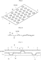
portions 21 and the second projectingportions 22 of the back foil portion Bf have the same size. However, projecting portions having different sizes may be formed on one or both of the front surface and the back surface of the back foil portion Bf.FIG. 17 is an illustration of an example of such configuration. Large projectingportions 21a and small projectingportions 21b are formed as the first projectingportions 21 on the front side, and large projectingportions 22a and small projectingportions 22b are formed as the second projectingportions 22 on the back side. The large projectingportions portions intermediate portion 23. - On the back foil portion Bf illustrated in
FIG. 17 , when the compression force (compression load in the width direction of the bearing gap C) applied to the back foil portion Bf gradually increases, theintermediate portion 23 is deformed, and then the large projectingportions portions - In the case in which the non-linearity is given to the resiliency characteristics of the back foil portion Bf as described above, when the compression load is small, the top foil portion Tf is likely to deform. Thus, even when the pressure of the air film is low (immediately after start of the rotation of the
shaft 6 or immediately before stop of the shaft 6), the wedge-shaped space is likely to be deformed. In contrast, when the compression load is large, the top foil portion Tf is less likely to deform. Thus, even when the pressure of the air film is high (normal rotation state of the shaft 6), the deformation of the top foil portion Bf is suppressed, thereby being capable of preventing leakage of air from the wedge-shaped space. Therefore, irrespective of low-speed rotation and high-speed rotation, theshaft 6 can be stably supported. -
FIG. 18 is an illustration of a configuration in which a large number of openingportions 26 are formed in theintermediate portion 23 of the back foil portion Bf illustrated inFIG. 9 to reduce the rigidity of theintermediate portion 23. With such a configuration, theintermediate portion 23 becomes more pliable, thereby being capable of further reducing the rigidity of the back foil portion Bf. In the embodiment illustrated inFIG. 18 , theintermediate portions 23 extend radially from each of the projectingportions portions portions 26 are adjusted to change the distribution state of the openingportions 26, thereby being capable of controlling the rigidity of theintermediate portion 23 and the rigidity of the back foil portion Bf at respective parts. - Any one of the structures configured to change the resiliency characteristics of the back foil portion Bf as described above, that is, any one of the structure configured to change the distribution density of the projecting
portion 21 and 22 (FIG. 13 ), the structure configured to change the sizes of the projectingportions 21 and 22 (FIG. 17 ), and the structure configured to change the distribution state of the opening portions 26 (FIG. 18 ) is selected, or two or more of the above-mentioned structures are suitably combined, to thereby enable optimization in resiliency characteristics of respective parts of the back foil portion Bf. In such a manner, respective parts of the bearing surface X can be set to optimum rigidities in terms of bearing function, thereby significantly enhancing the freedom in design of the bearing. An example of the projectingportions portions portions - In the description above, illustration is given of the so-called multi-arc type radial foil bearing as the foil bearing 10 as one example. However, the mode of the foil bearing to which the present invention is applicable is not limited to this. For example, the present invention is applicable also to the radial foil bearing 10 of a so-called leaf type illustrated in
FIG. 19 . In the leaf-type foil bearing, a plurality of foils 12 (leaves) each having a free end at one end on the rotation direction R side and a fixed end at another end on the side opposite to the rotation direction side are arrayed in the rotation direction R of theshaft 6. A region of eachfoil 12 on the rotation direction R side functions as the top foil portion Tf, and a region on the side opposite to the rotation direction side functions as the back foil portion Bf. In the radial foil bearing of the leaf type, the back foil portion Bf (illustrated in a dispersed dot pattern) of eachleaf 12 is formed of the projection-and-recess foil 20, thereby being capable of attaining the effect similar to the effect described above. - Moreover, the present invention is applicable also to the radial foil bearing 10 of the so-called bump type illustrated in
FIG. 20 . In the foil bearing 10 of the bump type, the entirety of the back foil portion Bf is formed of the projection-and-recess foil 20, thereby being capable of attaining the effect similar to the effect described above. InFIG. 20 , the back foil portion Bf continues on the entire circumference of the innerperipheral surface 11a of thefoil holder 11. However, the back foil portion Bf can be divided at one position or at a plurality of positions in the circumferential direction. In this case, each of the divided elements is formed of the projection-and-recess foil 20. - Further, the present invention is applicable also to a thrust foil bearing 30 illustrated in
FIG. 21. FIG. 21 is an illustration of a thrust foil bearing of a leaf type as an example of the thrust foil bearing 30. Also in this thrust foil bearing, as illustrated inFIG. 22 , the back foil portion Bf (illustrated in a dispersed dot pattern) of eachleaf 12 is formed of the projection-and-recess foil 20, thereby being capable of attaining the effect similar to the effect described above. - In the description above, description is made of an exemplary case in which the
shaft 6 is a rotary side member and thefoil holder 11 is a stationary side member. However, in contrast, the present invention can be applied also to the case in which theshaft 6 is the stationary side member and thefoil holder 11 is the rotary side member. However, in this case, thefoil 12 is the rotary side member, and hence it is required that thefoil 12 be designed in consideration of deformation of theentire foil 12 caused by a centrifugal force. - Moreover, the foil bearing according to the present invention can be used not only as a foil bearing for the above-mentioned gas turbine but also as, for example, a foil bearing for supporting a rotor of turbomachinery such as a supercharger. The present invention is not limited to the examples described above, and the foil bearing according to the present invention can be widely used as a bearing for vehicles such as automobiles as well as a bearing for an industrial device. Moreover, the foil bearings of the embodiments are air dynamic pressure bearings using air as pressure-generating fluid. However, the present invention is not limited thereto, and other gas can be used as the pressure-generating fluid. Alternatively, liquid such as water or oil can also be used.
-
- 6
- shaft
- 10
- foil bearing
- 11
- foil holder
- 11a
- inner peripheral surface
- 11b
- axial groove (mounting portion)
- 12
- foil
- 20
- projection-and-recess foil
- 21
- first projecting portion
- 21a
- large projecting portion
- 21b
- small projecting portion
- 22
- second projecting portion
- 22a
- large projecting portion
- 22b
- small projecting portion
- 23
- intermediate portion
- C
- bearing gap
- R
- rotation direction
- N
- direction orthogonal to rotation direction
- X
- bearing surface
Claims (6)
- A foil bearing, comprising:a top foil portion having a bearing surface opposed to a shaft to be supported; anda back foil portion, which is arranged on a back of the top foil portion, and is configured to elastically support the top foil portion,wherein the foil bearing is configured to support relative rotation of a shaft in a non-contact state with a fluid film generated in a bearing gap between the shaft and the bearing surface,wherein the back foil portion comprises:an intermediate portion being flat;first projecting portions projecting on a front side of the intermediate portion; andsecond projecting portions projecting on a back side of the intermediate portion.
- The foil bearing according to claim 1, wherein the first projecting portions and the second projecting portions are arrayed intermittently at least in a relative rotation direction of the shaft and in a direction orthogonal to the relative rotation direction along the bearing surface.
- The foil bearing according to claim 1 or 2, wherein the back foil portion comprises:a high-density region in which the first projecting portions and the second projecting portions are densely distributed; anda low-density region in which the first projecting portions and the second projecting portions are sparsely distributed.
- The foil bearing according to any one of claims 1 to 3, wherein the first projecting portions, the second projecting portion, or both the first projecting portions and the second projecting portions comprise:large projecting portions each having a large projection amount from the intermediate portion; andsmall projecting portions each having a small projection amount from the intermediate portion.
- The foil bearing according to any one of claims 1 to 4, wherein the intermediate portion has an opening portion.
- The foil bearing according to any one of claims 1 to 5, wherein the back foil portion has a maximum rigidity at a position corresponding to a maximum pressure generating portion in the bearing gap.
Applications Claiming Priority (2)
| Application Number | Priority Date | Filing Date | Title |
|---|---|---|---|
| JP2015234626A JP2017101726A (en) | 2015-12-01 | 2015-12-01 | Foil bearing |
| PCT/JP2016/083895 WO2017094501A1 (en) | 2015-12-01 | 2016-11-16 | Foil bearing |
Publications (2)
| Publication Number | Publication Date |
|---|---|
| EP3385553A1 true EP3385553A1 (en) | 2018-10-10 |
| EP3385553A4 EP3385553A4 (en) | 2019-09-11 |
Family
ID=58797317
Family Applications (1)
| Application Number | Title | Priority Date | Filing Date |
|---|---|---|---|
| EP16870439.3A Withdrawn EP3385553A4 (en) | 2015-12-01 | 2016-11-16 | Foil bearing |
Country Status (5)
| Country | Link |
|---|---|
| US (1) | US10487870B2 (en) |
| EP (1) | EP3385553A4 (en) |
| JP (1) | JP2017101726A (en) |
| CN (1) | CN108368879B (en) |
| WO (1) | WO2017094501A1 (en) |
Families Citing this family (4)
| Publication number | Priority date | Publication date | Assignee | Title |
|---|---|---|---|---|
| US10753226B1 (en) * | 2019-05-07 | 2020-08-25 | United States Of America As Represented By The Administrator Of Nasa | Reverse vortex ring (RVR) for dramatic improvements in rocket engine turbomachinery rotordynamic stability margins |
| CN110985526B (en) * | 2019-10-30 | 2024-05-03 | 珠海格力电器股份有限公司 | Pneumatic dynamic bearing, manufacturing method thereof and mechanical equipment |
| CN112178044B (en) * | 2020-08-31 | 2021-10-15 | 珠海格力电器股份有限公司 | Thrust bearing, device for compressing gas and method for adjusting thrust bearing |
| JP2025128631A (en) * | 2024-02-22 | 2025-09-03 | Ntn株式会社 | Radial Foil Bearings |
Family Cites Families (33)
| Publication number | Priority date | Publication date | Assignee | Title |
|---|---|---|---|---|
| US703563A (en) * | 1902-04-03 | 1902-07-01 | Sterling Elliott | Guard for third-rail systems. |
| DK76160C (en) * | 1950-05-10 | 1953-07-27 | Star Kugelhalter Gmbh Dt | Spring strap and a curved ring of corrugated steel sheet thereof. |
| GB703503A (en) * | 1951-06-29 | 1954-02-03 | London Welding Company Ltd | Improvements relating to reinforced concrete structures |
| US3434761A (en) | 1963-07-11 | 1969-03-25 | Garrett Corp | Hydrodynamic shaft bearing |
| US3635534A (en) * | 1969-08-06 | 1972-01-18 | Garrett Corp | Self-pressurizing bearings with resilient elements |
| US4195395A (en) * | 1976-05-24 | 1980-04-01 | The Garrett Corporation | Method of rotatably supporting two members with a foil bearing having a stiffener |
| US4295689A (en) * | 1979-08-30 | 1981-10-20 | United Technologies Corporation | Adjustable clearance foil journal bearing and method of manufacturing foil element therefor |
| JPS5644547A (en) * | 1979-09-19 | 1981-04-23 | Toto Ltd | Hot water supplying apparatus |
| JPS58191319A (en) * | 1982-05-01 | 1983-11-08 | Yasushi Itoga | Middle low speed no-lubrication bearing device |
| DE3442155A1 (en) * | 1984-11-17 | 1986-05-28 | SKF GmbH, 8720 Schweinfurt | Hydrodynamic foil bearing |
| US4668106A (en) * | 1984-11-19 | 1987-05-26 | The Garrett Corporation | Thrust bearing underspring |
| US4682900A (en) | 1985-12-19 | 1987-07-28 | The Garrett Corporation | Thrust bearing underspring |
| US4701060A (en) * | 1986-07-24 | 1987-10-20 | The Garrett Corporation | Foil journal bearing cooling |
| US4818123A (en) * | 1986-07-24 | 1989-04-04 | Allied-Signal Inc. | Foil journal bearing cooling |
| JPH0742980B2 (en) * | 1988-03-22 | 1995-05-15 | 石川島播磨重工業株式会社 | Hydrodynamic thrust fluid bearing |
| JPH0742981B2 (en) * | 1988-03-25 | 1995-05-15 | 石川島播磨重工業株式会社 | Hydrodynamic journal fluid bearing |
| US5228785A (en) * | 1990-12-20 | 1993-07-20 | Allied-Signal, Inc. | Stepped foil journal foil bearing |
| US5902049A (en) * | 1997-03-28 | 1999-05-11 | Mohawk Innovative Technology, Inc. | High load capacity compliant foil hydrodynamic journal bearing |
| JP4031614B2 (en) * | 1999-12-03 | 2008-01-09 | 三菱重工業株式会社 | Foil gas bearing |
| JP2003247542A (en) * | 2002-02-25 | 2003-09-05 | Shigetaka Yoshimoto | Foil gas bearing and its manufacturing method |
| JP4200751B2 (en) * | 2002-12-10 | 2008-12-24 | 株式会社ジェイテクト | Radial foil bearing |
| JP5487766B2 (en) * | 2009-07-09 | 2014-05-07 | 株式会社島津製作所 | Dynamic pressure gas bearing |
| JP5321332B2 (en) * | 2009-08-05 | 2013-10-23 | 株式会社島津製作所 | Dynamic pressure gas bearing |
| EP2455629A1 (en) * | 2010-11-19 | 2012-05-23 | Siemens Aktiengesellschaft | Radial gas foil bearing |
| JP5644547B2 (en) * | 2011-01-27 | 2014-12-24 | 株式会社島津製作所 | Dynamic pressure gas bearing |
| JP5751062B2 (en) * | 2011-07-22 | 2015-07-22 | 株式会社Ihi | Radial foil bearing |
| JP5862186B2 (en) * | 2011-10-13 | 2016-02-16 | 株式会社Ihi | Radial foil bearing |
| CN102434580B (en) * | 2011-11-04 | 2013-11-20 | 武汉航达航空科技发展有限公司 | Elastic support device for foil dynamic bearing and manufacturing method thereof |
| JP5929626B2 (en) * | 2012-08-14 | 2016-06-08 | 株式会社Ihi | Radial foil bearing |
| CN102927124B (en) * | 2012-10-10 | 2015-04-29 | 西安交通大学 | Multi-layer bubbled foil radial dynamic pressure gas bearing |
| WO2014098005A1 (en) * | 2012-12-19 | 2014-06-26 | Ntn株式会社 | Foil bearing |
| CN103267062B (en) * | 2013-05-16 | 2016-03-30 | 西安交通大学 | A kind of multilayer bubbling foil dynamical pressure gas lubricated thrust bearing |
| JP6372062B2 (en) * | 2013-09-19 | 2018-08-15 | 株式会社Ihi | Thrust bearing |
-
2015
- 2015-12-01 JP JP2015234626A patent/JP2017101726A/en active Pending
-
2016
- 2016-11-16 WO PCT/JP2016/083895 patent/WO2017094501A1/en not_active Ceased
- 2016-11-16 EP EP16870439.3A patent/EP3385553A4/en not_active Withdrawn
- 2016-11-16 US US15/780,016 patent/US10487870B2/en not_active Expired - Fee Related
- 2016-11-16 CN CN201680070302.3A patent/CN108368879B/en not_active Expired - Fee Related
Also Published As
| Publication number | Publication date |
|---|---|
| CN108368879A (en) | 2018-08-03 |
| US10487870B2 (en) | 2019-11-26 |
| EP3385553A4 (en) | 2019-09-11 |
| JP2017101726A (en) | 2017-06-08 |
| WO2017094501A1 (en) | 2017-06-08 |
| US20180355909A1 (en) | 2018-12-13 |
| CN108368879B (en) | 2020-09-15 |
Similar Documents
| Publication | Publication Date | Title |
|---|---|---|
| EP2937584B1 (en) | Foil bearing | |
| US9964143B2 (en) | Foil bearing and method for manufacturing thereof | |
| EP3096028B1 (en) | Foil bearing, and foil bearing unit and turbo machine each having same | |
| US10487870B2 (en) | Foil bearing | |
| EP3364059B1 (en) | Foil bearing | |
| EP3369952B1 (en) | Foil bearing, production method therefor, and intermediate product of foil bearing | |
| CN113614402B (en) | Thrust foil bearing, foil bearing unit, turbomachine and foil | |
| JP7577005B2 (en) | Foil Bearings | |
| JP6654081B2 (en) | Foil bearing | |
| JP2026054855A (en) | Foil bearing | |
| JP2017082912A (en) | Foil bearing | |
| WO2025177715A1 (en) | Radial foil bearing | |
| JP2024053880A (en) | Foil bearing |
Legal Events
| Date | Code | Title | Description |
|---|---|---|---|
| STAA | Information on the status of an ep patent application or granted ep patent |
Free format text: STATUS: THE INTERNATIONAL PUBLICATION HAS BEEN MADE |
|
| PUAI | Public reference made under article 153(3) epc to a published international application that has entered the european phase |
Free format text: ORIGINAL CODE: 0009012 |
|
| STAA | Information on the status of an ep patent application or granted ep patent |
Free format text: STATUS: REQUEST FOR EXAMINATION WAS MADE |
|
| 17P | Request for examination filed |
Effective date: 20180628 |
|
| AK | Designated contracting states |
Kind code of ref document: A1 Designated state(s): AL AT BE BG CH CY CZ DE DK EE ES FI FR GB GR HR HU IE IS IT LI LT LU LV MC MK MT NL NO PL PT RO RS SE SI SK SM TR |
|
| AX | Request for extension of the european patent |
Extension state: BA ME |
|
| DAV | Request for validation of the european patent (deleted) | ||
| DAX | Request for extension of the european patent (deleted) | ||
| A4 | Supplementary search report drawn up and despatched |
Effective date: 20190813 |
|
| RIC1 | Information provided on ipc code assigned before grant |
Ipc: F16C 27/02 20060101AFI20190807BHEP |
|
| STAA | Information on the status of an ep patent application or granted ep patent |
Free format text: STATUS: EXAMINATION IS IN PROGRESS |
|
| 17Q | First examination report despatched |
Effective date: 20210317 |
|
| STAA | Information on the status of an ep patent application or granted ep patent |
Free format text: STATUS: THE APPLICATION HAS BEEN WITHDRAWN |
|
| 18W | Application withdrawn |
Effective date: 20210830 |