EP3385533A1 - Piezo controlled inlet valve - Google Patents
Piezo controlled inlet valve Download PDFInfo
- Publication number
- EP3385533A1 EP3385533A1 EP18165539.0A EP18165539A EP3385533A1 EP 3385533 A1 EP3385533 A1 EP 3385533A1 EP 18165539 A EP18165539 A EP 18165539A EP 3385533 A1 EP3385533 A1 EP 3385533A1
- Authority
- EP
- European Patent Office
- Prior art keywords
- inlet valve
- piezoceramic
- pumping head
- disc
- head
- Prior art date
- Legal status (The legal status is an assumption and is not a legal conclusion. Google has not performed a legal analysis and makes no representation as to the accuracy of the status listed.)
- Granted
Links
Images
Classifications
-
- F—MECHANICAL ENGINEERING; LIGHTING; HEATING; WEAPONS; BLASTING
- F02—COMBUSTION ENGINES; HOT-GAS OR COMBUSTION-PRODUCT ENGINE PLANTS
- F02M—SUPPLYING COMBUSTION ENGINES IN GENERAL WITH COMBUSTIBLE MIXTURES OR CONSTITUENTS THEREOF
- F02M59/00—Pumps specially adapted for fuel-injection and not provided for in groups F02M39/00 -F02M57/00, e.g. rotary cylinder-block type of pumps
- F02M59/20—Varying fuel delivery in quantity or timing
- F02M59/36—Varying fuel delivery in quantity or timing by variably-timed valves controlling fuel passages to pumping elements or overflow passages
- F02M59/366—Valves being actuated electrically
- F02M59/367—Pump inlet valves of the check valve type being open when actuated
-
- F—MECHANICAL ENGINEERING; LIGHTING; HEATING; WEAPONS; BLASTING
- F02—COMBUSTION ENGINES; HOT-GAS OR COMBUSTION-PRODUCT ENGINE PLANTS
- F02M—SUPPLYING COMBUSTION ENGINES IN GENERAL WITH COMBUSTIBLE MIXTURES OR CONSTITUENTS THEREOF
- F02M59/00—Pumps specially adapted for fuel-injection and not provided for in groups F02M39/00 -F02M57/00, e.g. rotary cylinder-block type of pumps
- F02M59/20—Varying fuel delivery in quantity or timing
- F02M59/36—Varying fuel delivery in quantity or timing by variably-timed valves controlling fuel passages to pumping elements or overflow passages
- F02M59/366—Valves being actuated electrically
-
- F—MECHANICAL ENGINEERING; LIGHTING; HEATING; WEAPONS; BLASTING
- F02—COMBUSTION ENGINES; HOT-GAS OR COMBUSTION-PRODUCT ENGINE PLANTS
- F02M—SUPPLYING COMBUSTION ENGINES IN GENERAL WITH COMBUSTIBLE MIXTURES OR CONSTITUENTS THEREOF
- F02M59/00—Pumps specially adapted for fuel-injection and not provided for in groups F02M39/00 -F02M57/00, e.g. rotary cylinder-block type of pumps
- F02M59/44—Details, components parts, or accessories not provided for in, or of interest apart from, the apparatus of groups F02M59/02 - F02M59/42; Pumps having transducers, e.g. to measure displacement of pump rack or piston
- F02M59/46—Valves
- F02M59/466—Electrically operated valves, e.g. using electromagnetic or piezoelectric operating means
- F02M59/468—Electrically operated valves, e.g. using electromagnetic or piezoelectric operating means using piezoelectric operating means
-
- F—MECHANICAL ENGINEERING; LIGHTING; HEATING; WEAPONS; BLASTING
- F02—COMBUSTION ENGINES; HOT-GAS OR COMBUSTION-PRODUCT ENGINE PLANTS
- F02M—SUPPLYING COMBUSTION ENGINES IN GENERAL WITH COMBUSTIBLE MIXTURES OR CONSTITUENTS THEREOF
- F02M2200/00—Details of fuel-injection apparatus, not otherwise provided for
- F02M2200/21—Fuel-injection apparatus with piezoelectric or magnetostrictive elements
Definitions
- the present invention relates to an inlet valve assembly of a high pressure fuel pump, said assembly having a piezo-controlled direct acting valve member.
- a direct injection equipment comprises a high pressure pump in which fuel received from a low pressure tank is pressurised prior to be delivered to a common rail and to injectors.
- the fuel in pressurised in a compression chamber which inlet is controlled by an inlet valve member that opens or closes under the influence of pressure difference between the upstream inlet conduit and said downstream compression chamber.
- Digital inlet valve (DIV) are added to limit the fuel entry in the compression chamber to the necessary volume demanded to be pressurised by the engine.
- a solenoid actuator may be added so that a magnetic armature cooperates with the valve member either to fully control the operation of the valve member or simply to speed-up the opening or to retard the closing, the valve member remaining generally passive.
- Such electro-valve are structurally large, complex and difficult to pilot.
- a pumping head of a fuel injection equipment high pressure pump comprising a body provided with a main bore extending along a main axis from a lower opening to an upper end partially defining a compression chamber wherein are arranged an outlet opening and an inlet opening forming an axial guiding bore extending through said body from a seat face surrounding the inlet opening in the bore to a top face of the body.
- the pumping head further comprises an inlet valve assembly controlling said inlet opening an comprising an inlet valve body fixed atop the pumping head body thus defining an inner space, an inlet valve member having a head member defining a closing face cooperating with said seat face and, a stem member axially guided in said guiding bore and extending from said head member to an upper end protruding in said inner space and, a piezoceramic actuator fixed in said body and to said stem upper end.
- an inlet valve assembly controlling said inlet opening an comprising an inlet valve body fixed atop the pumping head body thus defining an inner space, an inlet valve member having a head member defining a closing face cooperating with said seat face and, a stem member axially guided in said guiding bore and extending from said head member to an upper end protruding in said inner space and, a piezoceramic actuator fixed in said body and to said stem upper end.
- said piezoceramic actuator is a disc-like member provided with a central orifice, the outer edge of said disc-like member being fixed in the inlet valve body and, the stem upper end being fixed into the central orifice.
- the pumping head further comprises a stem upper end cap member arranged atop the stem upper end and inside the central orifice of the piezoceramic member. It also comprises a flexible sealing membrane arranged in the inlet body inner space and preventing, in use, fuel to contact the piezoceramic disc.
- said membrane has an outer edge pinched between a face of the inlet valve body and the outer edge of the piezoceramic disc and, a central opening pinched between the stem upper end cap member and the piezoceramic disc.
- the inlet valve body comprises an annular member fixed on the pumping head body and defining the peripheral wall of the inner space and, a valve body cap member fixed on said annular member and closing said inner space.
- the disc membrane is arranged so its outer edge is against a top annular face of the annular member and the outer edge of said piezoceramic disc-like member, the valve body cap member covering the piezoceramic disc and being firmly tightened to the body annular member, thus pinching the piezoceramic disc and the membrane between the cover and the annular body member.
- the pumping head further comprises electrical wires connected to the piezoceramic disc and extending outside the inlet valve body so that, in use, command signals may be sent from a command unit to said piezoceramic actuator.
- the invention also extends to a high pressure fuel pump comprising a cambox and a pumping head as described above and wherein, in use, a camshaft rotates in the cambox imparting reciprocal displacements to a plunger guided in the main bore and varying the volume of the compression chamber.
- a fuel injection equipment comprising a high pressure pump as here above mentioned and a command unit connected to the inlet valve piezoceramic disc and adapted to send command signal for operating the inlet valve member.
- the invention also extends to a method of controlling such fuel injection equipment, the method comprising the step of:
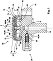
- figure 1 is an axial section of a pumping head of a HP pump as per the invention.
- a fuel injection equipment comprises a high pressure pump 10 that receives fuel at low pressure, pressurises it and delivers it to a common rail.
- the pump 10 has a pumping head 12 fixed on a cambox, not shown, the head 12 having a body 14 provided with a blind bore 16 which extends along a pumping axis X and in which, in use, reciprocates a plunger, not shown, that cooperates with a camshaft rotating in the cambox.
- Said bore 16 is open at a lower end of the head 12 to enable the plunger to extend in the cambox and, at the upper blind end, said bore 16 partially defines a compression chamber 18 in which radially opens an outlet channel 20 controlled by an outlet check valve 22 and, axially opens an inlet valve guiding bore 24 controlled by an inlet valve assembly 26.
- the inlet valve guiding bore 24 is coaxial to the bore 16 and it upwardly extends from a lower end opening in the blind end of the bore 16, said lower opening being surrounded by a seat face 28 defined on said end face of the bore to, an upper end opening on a top face 30 of the head body.
- the pumping head top face 30 From said pumping head top face 30 upwardly protrudes a cylindrical wall 32 having a right-angled triangle wall section defining an cylindrical outer face 34 and, a frustoconical inner face 36 downwardly pointing toward the head body 14, said cylindrical wall 32 axially extending about the pumping axis X.
- the pumping head top face 30 further comprises a conical member 38 axially upwardly protruding in the middle of said cylindrical wall 32, the inlet valve guiding bore 24 axially extending in said conical member 38 and opening at the top of it.
- the pumping head body 14 is further provided with a fuel inlet channel 40 drilled in said conical member 38 and extending from the top face 30 of the pumping head, in an area close to the base of said conical member 38, to an annular chamber defined in the inlet valve guiding bore 24 above said seat face 28.
- the inlet valve assembly 26 has a body 42 comprising a main member 44 and a cap member 46, said main member 44 having a base 48, fixed on the top face 30 of the pumping head body and, an annular tubular portion 50 axially protruding from said base 48 and adjusted onto the outer face 34 of the cylindrical wall. Said tubular portion 40 is covered by the cap member 46 having a transverse wall 52 closing the inlet body tubular portion 50 and a peripheral wall 54 internally threaded and complementary engaged and tightened onto a male thread provided on the outer face of the inlet body tubular portion 50.
- the inlet valve body 42 and the top face 30 of the pumping head together define an inner space S in which opens the inlet valve guiding bore 24 and the fuel inlet channel 40.
- Said inlet valve assembly 26 further comprises a poppet inlet valve member 56 having a stem 58 axially guided in the guiding bore 24 and extending between an upper end 60 protruding in the inner space S and a lower end protruding in the compression chamber 18, said lower end enlarging to form a head member 62 defining a closing face adapted to cooperate with the seat face 28 to seal said blind end of the bore.
- the upper end 60 of the stem is covered by a cap member 64 defining a closed cylindrical portion 66 wherein said stem upper end 60 is inserted and, a crimping annular member 68 enabling to crimp said cap member 64 on the stem.
- the stem upper end 60 covered by said closed portion 66 of the cap are inserted in an orifice 70 centrally provided in a disc-like piezoceramic member 72 that transversally extends parallel to the transverse wall 52 of the cap toward an outer circular edge 74 that is between said body cap member 46 and the inlet body tubular portion 50.
- a sealing flexible membrane 76 adapted to prevent fuel contact to the piezoceramic disc 72 is arranged in the inner space S, lying against the under face of said disc member 72, the membrane 76 having a peripheral area sandwiched between the disc member 72 and the inlet body tubular portion 50. Centrally, the membrane 76 is holed and fixed to the crimping annular member 68.
- the pumping head 12 and the inlet valve assembly 26 further comprise a fuel inlet conduit opening in the inner space S and enabling, in use, fuel to flow from a low pressure tank and to fill said inner space S and, electrical connection means, such as cables, wires and connectors, enabling to electrically connect said piezoceramic disc member 72 to an external command unit that will deliver relevant electrical command signals.
- electrical connection means such as cables, wires and connectors, enabling to electrically connect said piezoceramic disc member 72 to an external command unit that will deliver relevant electrical command signals.
- the piezoceramic disc 72 In a first step the piezoceramic disc 72 is not energised, it does not receive electrical signals, and it remains in a neutral planar position. In said neutral position the inlet valve member is upwardly pulled sealing the fluid communication between the inlet channel and the compression chamber 18.
- the piezoceramic disc 72 is energized and, upon receiving such electrical signal, the disc deforms and centrally balloons, the outer edge 74 of the disc remaining pinched. As the disc 72 balloons, the disc central area downwardly moves pushing the inlet valve member 56 in an open position where the closing face of the head lifts away from the seat face 28 of the bore, enabling fuel passage in and out the compression chamber.
- the opening and closing of the inlet is directly controlled, therefore, the inlet valve member can be opened or closed, earlier or later than it would naturally do under the sole influence of the pressure differences in the inner space S and in the compression chamber 18, this to optimise the filling of the compression chamber to the necessary quantity demanded by an engine.
Landscapes
- Engineering & Computer Science (AREA)
- Chemical & Material Sciences (AREA)
- Combustion & Propulsion (AREA)
- Mechanical Engineering (AREA)
- General Engineering & Computer Science (AREA)
- Physics & Mathematics (AREA)
- Electromagnetism (AREA)
- Fuel-Injection Apparatus (AREA)
Abstract
Description
- The present invention relates to an inlet valve assembly of a high pressure fuel pump, said assembly having a piezo-controlled direct acting valve member.
- A direct injection equipment comprises a high pressure pump in which fuel received from a low pressure tank is pressurised prior to be delivered to a common rail and to injectors. The fuel in pressurised in a compression chamber which inlet is controlled by an inlet valve member that opens or closes under the influence of pressure difference between the upstream inlet conduit and said downstream compression chamber. Digital inlet valve (DIV) are added to limit the fuel entry in the compression chamber to the necessary volume demanded to be pressurised by the engine. A solenoid actuator may be added so that a magnetic armature cooperates with the valve member either to fully control the operation of the valve member or simply to speed-up the opening or to retard the closing, the valve member remaining generally passive. Such electro-valve are structurally large, complex and difficult to pilot.
- Accordingly, it is an object of the present invention to resolve the above mentioned problems in providing a pumping head of a fuel injection equipment high pressure pump, said pumping head comprising a body provided with a main bore extending along a main axis from a lower opening to an upper end partially defining a compression chamber wherein are arranged an outlet opening and an inlet opening forming an axial guiding bore extending through said body from a seat face surrounding the inlet opening in the bore to a top face of the body.
- Advantageously, the pumping head further comprises an inlet valve assembly controlling said inlet opening an comprising an inlet valve body fixed atop the pumping head body thus defining an inner space, an inlet valve member having a head member defining a closing face cooperating with said seat face and, a stem member axially guided in said guiding bore and extending from said head member to an upper end protruding in said inner space and, a piezoceramic actuator fixed in said body and to said stem upper end.
- Also, said piezoceramic actuator is a disc-like member provided with a central orifice, the outer edge of said disc-like member being fixed in the inlet valve body and, the stem upper end being fixed into the central orifice.
- The pumping head further comprises a stem upper end cap member arranged atop the stem upper end and inside the central orifice of the piezoceramic member. It also comprises a flexible sealing membrane arranged in the inlet body inner space and preventing, in use, fuel to contact the piezoceramic disc.
- Also, said membrane has an outer edge pinched between a face of the inlet valve body and the outer edge of the piezoceramic disc and, a central opening pinched between the stem upper end cap member and the piezoceramic disc.
- Also, the inlet valve body comprises an annular member fixed on the pumping head body and defining the peripheral wall of the inner space and, a valve body cap member fixed on said annular member and closing said inner space.
- Also, the disc membrane is arranged so its outer edge is against a top annular face of the annular member and the outer edge of said piezoceramic disc-like member, the valve body cap member covering the piezoceramic disc and being firmly tightened to the body annular member, thus pinching the piezoceramic disc and the membrane between the cover and the annular body member.
- The pumping head further comprises electrical wires connected to the piezoceramic disc and extending outside the inlet valve body so that, in use, command signals may be sent from a command unit to said piezoceramic actuator.
- The invention also extends to a high pressure fuel pump comprising a cambox and a pumping head as described above and wherein, in use, a camshaft rotates in the cambox imparting reciprocal displacements to a plunger guided in the main bore and varying the volume of the compression chamber.
- It also extend to a fuel injection equipment comprising a high pressure pump as here above mentioned and a command unit connected to the inlet valve piezoceramic disc and adapted to send command signal for operating the inlet valve member.
- The invention also extends to a method of controlling such fuel injection equipment, the method comprising the step of:
- energizing the piezoceramic disc so that the piezoceramic disc deforms forcing the inlet valve member to open.
- The present invention is now described by way of example with reference to the accompanying drawing in which
figure 1 is an axial section of a pumping head of a HP pump as per the invention. - A fuel injection equipment comprises a
high pressure pump 10 that receives fuel at low pressure, pressurises it and delivers it to a common rail. Thepump 10 has a pumpinghead 12 fixed on a cambox, not shown, thehead 12 having abody 14 provided with ablind bore 16 which extends along a pumping axis X and in which, in use, reciprocates a plunger, not shown, that cooperates with a camshaft rotating in the cambox. Saidbore 16 is open at a lower end of thehead 12 to enable the plunger to extend in the cambox and, at the upper blind end, saidbore 16 partially defines acompression chamber 18 in which radially opens anoutlet channel 20 controlled by anoutlet check valve 22 and, axially opens an inlet valve guidingbore 24 controlled by aninlet valve assembly 26. In the example embodiment of the figure, the inlet valve guidingbore 24 is coaxial to thebore 16 and it upwardly extends from a lower end opening in the blind end of thebore 16, said lower opening being surrounded by aseat face 28 defined on said end face of the bore to, an upper end opening on atop face 30 of the head body. From said pumping headtop face 30 upwardly protrudes acylindrical wall 32 having a right-angled triangle wall section defining an cylindricalouter face 34 and, a frustoconicalinner face 36 downwardly pointing toward thehead body 14, saidcylindrical wall 32 axially extending about the pumping axis X. The pumping headtop face 30 further comprises aconical member 38 axially upwardly protruding in the middle of saidcylindrical wall 32, the inlet valve guiding bore 24 axially extending in saidconical member 38 and opening at the top of it. The pumpinghead body 14 is further provided with afuel inlet channel 40 drilled in saidconical member 38 and extending from thetop face 30 of the pumping head, in an area close to the base of saidconical member 38, to an annular chamber defined in the inlet valve guidingbore 24 above saidseat face 28. - The
inlet valve assembly 26 has abody 42 comprising amain member 44 and acap member 46, saidmain member 44 having abase 48, fixed on thetop face 30 of the pumping head body and, an annulartubular portion 50 axially protruding from saidbase 48 and adjusted onto theouter face 34 of the cylindrical wall. Saidtubular portion 40 is covered by thecap member 46 having atransverse wall 52 closing the inlet bodytubular portion 50 and aperipheral wall 54 internally threaded and complementary engaged and tightened onto a male thread provided on the outer face of the inlet bodytubular portion 50. As visible on the figure, theinlet valve body 42 and thetop face 30 of the pumping head together define an inner space S in which opens the inlet valve guidingbore 24 and thefuel inlet channel 40. - Said
inlet valve assembly 26 further comprises a poppet inlet valve member 56 having a stem 58 axially guided in theguiding bore 24 and extending between anupper end 60 protruding in the inner space S and a lower end protruding in thecompression chamber 18, said lower end enlarging to form a head member 62 defining a closing face adapted to cooperate with theseat face 28 to seal said blind end of the bore. - The
upper end 60 of the stem is covered by a cap member 64 defining a closed cylindrical portion 66 wherein said stemupper end 60 is inserted and, a crimpingannular member 68 enabling to crimp said cap member 64 on the stem. The stemupper end 60 covered by said closed portion 66 of the cap are inserted in anorifice 70 centrally provided in a disc-likepiezoceramic member 72 that transversally extends parallel to thetransverse wall 52 of the cap toward an outercircular edge 74 that is between saidbody cap member 46 and the inlet bodytubular portion 50. Moreover, a sealingflexible membrane 76 adapted to prevent fuel contact to thepiezoceramic disc 72 is arranged in the inner space S, lying against the under face of saiddisc member 72, themembrane 76 having a peripheral area sandwiched between thedisc member 72 and the inlet bodytubular portion 50. Centrally, themembrane 76 is holed and fixed to the crimpingannular member 68. - Not shown, the
pumping head 12 and theinlet valve assembly 26 further comprise a fuel inlet conduit opening in the inner space S and enabling, in use, fuel to flow from a low pressure tank and to fill said inner space S and, electrical connection means, such as cables, wires and connectors, enabling to electrically connect saidpiezoceramic disc member 72 to an external command unit that will deliver relevant electrical command signals. - The operation of said pumping
head 12 is now described focusing mainly on the moves of the inlet valve member. - In a first step the
piezoceramic disc 72 is not energised, it does not receive electrical signals, and it remains in a neutral planar position. In said neutral position the inlet valve member is upwardly pulled sealing the fluid communication between the inlet channel and thecompression chamber 18. - In a subsequent second step, the
piezoceramic disc 72 is energized and, upon receiving such electrical signal, the disc deforms and centrally balloons, theouter edge 74 of the disc remaining pinched. As thedisc 72 balloons, the disc central area downwardly moves pushing the inlet valve member 56 in an open position where the closing face of the head lifts away from theseat face 28 of the bore, enabling fuel passage in and out the compression chamber. - Thanks to said piezoceramic actuation of the inlet valve member, the opening and closing of the inlet is directly controlled, therefore, the inlet valve member can be opened or closed, earlier or later than it would naturally do under the sole influence of the pressure differences in the inner space S and in the
compression chamber 18, this to optimise the filling of the compression chamber to the necessary quantity demanded by an engine. -
- X
- pumping axis
- S
- inner space
- 10
- high pressure pump
- 12
- pumping head
- 14
- body of the pumping head
- 16
- bore
- 18
- compression chamber
- 20
- outlet channel
- 22
- outlet valve
- 24
- inlet valve guiding bore
- 26
- inlet valve assembly
- 28
- seat face
- 30
- top face of the pumping head
- 32
- cylindrical wall
- 34
- outer face
- 36
- inner face
- 38
- conical member
- 40
- inlet channel
- 42
- inlet valve body
- 44
- main member of the inlet valve body
- 46
- body cap member
- 48
- body base of the main member
- 50
- body tubular portion
- 52
- transverse wall of the cap
- 54
- peripheral wall of the cap
- 56
- inlet valve member
- 58
- stem
- 60
- upper end of the stem
- 62
- inlet valve head
- 64
- cap member
- 66
- closed portion
- 68
- crimping annular member
- 70
- orifice
- 72
- piezoceramic disc
- 74
- outer edge
- 76
- membrane
Claims (11)
- Pumping head (12) of a fuel injection equipment high pressure pump (10), said pumping head (12) comprising a body (14) provided with a main bore (16) extending along a main axis (X) from a lower opening to an upper end partially defining a compression chamber (18) wherein are arranged an outlet opening and an inlet opening forming an axial guiding bore (24) extending through said body (14) from a seat face (28) surrounding the inlet opening in the bore to a top face (30) of the body and wherein,
the pumping head (12) further comprising an inlet valve assembly (26) controlling said inlet opening an comprising an inlet valve body (42) fixed atop the pumping head body thus defining an inner space (S), an inlet valve member (56) having a head member (62) defining a closing face cooperating with said seat face (28) and, a stem member (58) axially guided in said guiding bore (24) and extending from said head member (62) to an upper end (60) protruding in said inner space (S) and, a piezoceramic actuator (72) fixed in said body (42) and to said stem upper end (60). - Pumping head (12) as claimed in the preceding claim wherein said piezoceramic actuator (72) is a disc-like member provided with a central orifice (70), the outer edge (74) of said disc-like member being fixed in the inlet valve body (42) and, the stem upper end (60) being fixed into the central orifice (70).
- Pumping head (12) as claimed in claim 2 further comprising a stem upper end cap member (64) arranged atop the stem upper end (60) and inside the central orifice (70) of the piezoceramic member.
- Pumping head (12) as claimed in claim 3 further comprising a flexible sealing membrane (76) arranged in the inlet body inner space (S) and preventing, in use, fuel to contact the piezoceramic disc (72).
- Pumping head (12) as claimed in claim 4 wherein said membrane (76) has an outer edge pinched between a face of the inlet valve body (42) and the outer edge of the piezoceramic disc (72) and, a central opening pinched between the stem upper end cap member (64) and the piezoceramic disc (72).
- Pumping head (12) as claimed in any one of the preceding claims wherein the inlet valve body (42) comprises an annular member (44) fixed on the pumping head body and defining the peripheral wall of the inner space (S) and, a valve body cap member (46) fixed on said annular member (44) and closing said inner space (S).
- Pumping head (12) as claimed in the combination of claims 5 and 6 wherein the disc membrane (76) is arranged so its outer edge is against a top annular face of the annular member (44) and the outer edge of said piezoceramic disc-like member (72), the valve body cap member (46) covering the piezoceramic disc (72) and being firmly tightened to the body annular member (44), thus pinching the piezoceramic disc and the membrane between the cover and the annular body member.
- Pumping head (12) as claimed in any one of the preceding claims further comprising electrical wires connected to the piezoceramic disc (72) and extending outside the inlet valve body (42) so that, in use, command signals may be sent from a command unit to said piezoceramic actuator.
- High pressure fuel pump (10) comprising a cambox and a pumping head (12) as claimed in any of the preceding claims and wherein, in use, a camshaft rotates in the cambox imparting reciprocal displacements to a plunger guided in the main bore (16) and varying the volume of the compression chamber (18).
- Fuel injection equipment comprising a high pressure pump (10) as claimed in claim 9 and a command unit connected to the inlet valve piezoceramic disc (72) and adapted to send command signal for operating the inlet valve member (56).
- Method of controlling a fuel injection equipment as claimed in claim 10, the method comprising the step of:- energizing the piezoceramic disc (72) so that the piezoceramic disc deforms forcing the inlet valve member (56) to open.
Applications Claiming Priority (1)
| Application Number | Priority Date | Filing Date | Title |
|---|---|---|---|
| GB1705399.2A GB2561189A (en) | 2017-04-04 | 2017-04-04 | Piezo controlled inlet valve |
Publications (2)
| Publication Number | Publication Date |
|---|---|
| EP3385533A1 true EP3385533A1 (en) | 2018-10-10 |
| EP3385533B1 EP3385533B1 (en) | 2020-07-29 |
Family
ID=58682590
Family Applications (1)
| Application Number | Title | Priority Date | Filing Date |
|---|---|---|---|
| EP18165539.0A Active EP3385533B1 (en) | 2017-04-04 | 2018-04-03 | Piezo controlled inlet valve |
Country Status (2)
| Country | Link |
|---|---|
| EP (1) | EP3385533B1 (en) |
| GB (1) | GB2561189A (en) |
Citations (3)
| Publication number | Priority date | Publication date | Assignee | Title |
|---|---|---|---|---|
| DE102008018018A1 (en) * | 2008-04-09 | 2009-10-15 | Continental Automotive Gmbh | Pump for conveying a fluid |
| DE102012210087A1 (en) * | 2012-06-15 | 2013-12-19 | Robert Bosch Gmbh | High-pressure fuel pump for fuel injection system, has valve element that is brought in open position with large opening stroke by actuator actuation or non-actuation independent of pressure difference between inlet and pump working space |
| DE102012218552A1 (en) * | 2012-10-11 | 2014-04-17 | Continental Automotive Gmbh | High pressure pump for common-rail injection system, for compressing fuel on high pressure in diesel engine of motor car, has hydraulic damper element connected with fuel supply lines and arranged in pump casing |
Family Cites Families (3)
| Publication number | Priority date | Publication date | Assignee | Title |
|---|---|---|---|---|
| EP1296061A3 (en) * | 2001-09-21 | 2005-03-16 | Hitachi, Ltd. | High pressure fuel pump |
| EP2687712B1 (en) * | 2012-07-19 | 2015-12-09 | Delphi International Operations Luxembourg S.à r.l. | Valve assembly |
| DE102012217032A1 (en) * | 2012-09-21 | 2014-04-17 | Robert Bosch Gmbh | High pressure pump for fuel injection system of combustion engine, has inlet valve directly or indirectly connected with position actuating part to adjust valve lift of valve lifter, and polymer actuator connected with actuating part |
-
2017
- 2017-04-04 GB GB1705399.2A patent/GB2561189A/en not_active Withdrawn
-
2018
- 2018-04-03 EP EP18165539.0A patent/EP3385533B1/en active Active
Patent Citations (3)
| Publication number | Priority date | Publication date | Assignee | Title |
|---|---|---|---|---|
| DE102008018018A1 (en) * | 2008-04-09 | 2009-10-15 | Continental Automotive Gmbh | Pump for conveying a fluid |
| DE102012210087A1 (en) * | 2012-06-15 | 2013-12-19 | Robert Bosch Gmbh | High-pressure fuel pump for fuel injection system, has valve element that is brought in open position with large opening stroke by actuator actuation or non-actuation independent of pressure difference between inlet and pump working space |
| DE102012218552A1 (en) * | 2012-10-11 | 2014-04-17 | Continental Automotive Gmbh | High pressure pump for common-rail injection system, for compressing fuel on high pressure in diesel engine of motor car, has hydraulic damper element connected with fuel supply lines and arranged in pump casing |
Also Published As
| Publication number | Publication date |
|---|---|
| EP3385533B1 (en) | 2020-07-29 |
| GB2561189A (en) | 2018-10-10 |
| GB2561189A8 (en) | 2018-11-28 |
| GB201705399D0 (en) | 2017-05-17 |
Similar Documents
| Publication | Publication Date | Title |
|---|---|---|
| US9970399B2 (en) | Valve assembly | |
| US5694903A (en) | Fuel injection valve for internal combustion engines | |
| EP0548916A1 (en) | Electromagnetic fuel injection valve | |
| US10502170B2 (en) | Fuel injector | |
| EP2687712B1 (en) | Valve assembly | |
| EP3385533B1 (en) | Piezo controlled inlet valve | |
| CN206035697U (en) | Pressure control valve subassembly and fuel injection apparatus | |
| US10415523B2 (en) | Fuel injection valve | |
| JP2017531128A (en) | Control valve for fuel injector | |
| CN108474339B (en) | fuel injector | |
| JP2004506126A (en) | Fuel injection valve | |
| CN106133305B (en) | Spool with discharge pipe | |
| CN109196210A (en) | For measuring the gas trap of fuel gas | |
| EP3208456A1 (en) | Nozzle assembly and fuel injector | |
| EP3504423B1 (en) | Control valve assembly of a fuel injector | |
| US11208975B2 (en) | Fuel injector | |
| EP2647826B1 (en) | Valve arrangement | |
| JP2010236368A (en) | Fuel injection valve | |
| CN108291519B (en) | Control valve device for fuel injector | |
| EP3580444A1 (en) | Fuel injector | |
| WO2019068566A1 (en) | Fuel injector |
Legal Events
| Date | Code | Title | Description |
|---|---|---|---|
| PUAI | Public reference made under article 153(3) epc to a published international application that has entered the european phase |
Free format text: ORIGINAL CODE: 0009012 |
|
| STAA | Information on the status of an ep patent application or granted ep patent |
Free format text: STATUS: THE APPLICATION HAS BEEN PUBLISHED |
|
| AK | Designated contracting states |
Kind code of ref document: A1 Designated state(s): AL AT BE BG CH CY CZ DE DK EE ES FI FR GB GR HR HU IE IS IT LI LT LU LV MC MK MT NL NO PL PT RO RS SE SI SK SM TR |
|
| AX | Request for extension of the european patent |
Extension state: BA ME |
|
| STAA | Information on the status of an ep patent application or granted ep patent |
Free format text: STATUS: REQUEST FOR EXAMINATION WAS MADE |
|
| 17P | Request for examination filed |
Effective date: 20190410 |
|
| RBV | Designated contracting states (corrected) |
Designated state(s): AL AT BE BG CH CY CZ DE DK EE ES FI FR GB GR HR HU IE IS IT LI LT LU LV MC MK MT NL NO PL PT RO RS SE SI SK SM TR |
|
| GRAP | Despatch of communication of intention to grant a patent |
Free format text: ORIGINAL CODE: EPIDOSNIGR1 |
|
| STAA | Information on the status of an ep patent application or granted ep patent |
Free format text: STATUS: GRANT OF PATENT IS INTENDED |
|
| RIC1 | Information provided on ipc code assigned before grant |
Ipc: F02M 59/36 20060101AFI20200117BHEP |
|
| INTG | Intention to grant announced |
Effective date: 20200219 |
|
| GRAS | Grant fee paid |
Free format text: ORIGINAL CODE: EPIDOSNIGR3 |
|
| GRAA | (expected) grant |
Free format text: ORIGINAL CODE: 0009210 |
|
| STAA | Information on the status of an ep patent application or granted ep patent |
Free format text: STATUS: THE PATENT HAS BEEN GRANTED |
|
| AK | Designated contracting states |
Kind code of ref document: B1 Designated state(s): AL AT BE BG CH CY CZ DE DK EE ES FI FR GB GR HR HU IE IS IT LI LT LU LV MC MK MT NL NO PL PT RO RS SE SI SK SM TR |
|
| REG | Reference to a national code |
Ref country code: CH Ref legal event code: EP |
|
| REG | Reference to a national code |
Ref country code: AT Ref legal event code: REF Ref document number: 1296099 Country of ref document: AT Kind code of ref document: T Effective date: 20200815 |
|
| REG | Reference to a national code |
Ref country code: IE Ref legal event code: FG4D |
|
| REG | Reference to a national code |
Ref country code: DE Ref legal event code: R096 Ref document number: 602018006342 Country of ref document: DE |
|
| REG | Reference to a national code |
Ref country code: LT Ref legal event code: MG4D |
|
| REG | Reference to a national code |
Ref country code: NL Ref legal event code: MP Effective date: 20200729 |
|
| REG | Reference to a national code |
Ref country code: AT Ref legal event code: MK05 Ref document number: 1296099 Country of ref document: AT Kind code of ref document: T Effective date: 20200729 |
|
| PG25 | Lapsed in a contracting state [announced via postgrant information from national office to epo] |
Ref country code: AT Free format text: LAPSE BECAUSE OF FAILURE TO SUBMIT A TRANSLATION OF THE DESCRIPTION OR TO PAY THE FEE WITHIN THE PRESCRIBED TIME-LIMIT Effective date: 20200729 Ref country code: BG Free format text: LAPSE BECAUSE OF FAILURE TO SUBMIT A TRANSLATION OF THE DESCRIPTION OR TO PAY THE FEE WITHIN THE PRESCRIBED TIME-LIMIT Effective date: 20201029 Ref country code: SE Free format text: LAPSE BECAUSE OF FAILURE TO SUBMIT A TRANSLATION OF THE DESCRIPTION OR TO PAY THE FEE WITHIN THE PRESCRIBED TIME-LIMIT Effective date: 20200729 Ref country code: LT Free format text: LAPSE BECAUSE OF FAILURE TO SUBMIT A TRANSLATION OF THE DESCRIPTION OR TO PAY THE FEE WITHIN THE PRESCRIBED TIME-LIMIT Effective date: 20200729 Ref country code: ES Free format text: LAPSE BECAUSE OF FAILURE TO SUBMIT A TRANSLATION OF THE DESCRIPTION OR TO PAY THE FEE WITHIN THE PRESCRIBED TIME-LIMIT Effective date: 20200729 Ref country code: HR Free format text: LAPSE BECAUSE OF FAILURE TO SUBMIT A TRANSLATION OF THE DESCRIPTION OR TO PAY THE FEE WITHIN THE PRESCRIBED TIME-LIMIT Effective date: 20200729 Ref country code: PT Free format text: LAPSE BECAUSE OF FAILURE TO SUBMIT A TRANSLATION OF THE DESCRIPTION OR TO PAY THE FEE WITHIN THE PRESCRIBED TIME-LIMIT Effective date: 20201130 Ref country code: GR Free format text: LAPSE BECAUSE OF FAILURE TO SUBMIT A TRANSLATION OF THE DESCRIPTION OR TO PAY THE FEE WITHIN THE PRESCRIBED TIME-LIMIT Effective date: 20201030 Ref country code: FI Free format text: LAPSE BECAUSE OF FAILURE TO SUBMIT A TRANSLATION OF THE DESCRIPTION OR TO PAY THE FEE WITHIN THE PRESCRIBED TIME-LIMIT Effective date: 20200729 Ref country code: NO Free format text: LAPSE BECAUSE OF FAILURE TO SUBMIT A TRANSLATION OF THE DESCRIPTION OR TO PAY THE FEE WITHIN THE PRESCRIBED TIME-LIMIT Effective date: 20201029 |
|
| PG25 | Lapsed in a contracting state [announced via postgrant information from national office to epo] |
Ref country code: RS Free format text: LAPSE BECAUSE OF FAILURE TO SUBMIT A TRANSLATION OF THE DESCRIPTION OR TO PAY THE FEE WITHIN THE PRESCRIBED TIME-LIMIT Effective date: 20200729 Ref country code: PL Free format text: LAPSE BECAUSE OF FAILURE TO SUBMIT A TRANSLATION OF THE DESCRIPTION OR TO PAY THE FEE WITHIN THE PRESCRIBED TIME-LIMIT Effective date: 20200729 Ref country code: LV Free format text: LAPSE BECAUSE OF FAILURE TO SUBMIT A TRANSLATION OF THE DESCRIPTION OR TO PAY THE FEE WITHIN THE PRESCRIBED TIME-LIMIT Effective date: 20200729 Ref country code: IS Free format text: LAPSE BECAUSE OF FAILURE TO SUBMIT A TRANSLATION OF THE DESCRIPTION OR TO PAY THE FEE WITHIN THE PRESCRIBED TIME-LIMIT Effective date: 20201129 |
|
| PG25 | Lapsed in a contracting state [announced via postgrant information from national office to epo] |
Ref country code: NL Free format text: LAPSE BECAUSE OF FAILURE TO SUBMIT A TRANSLATION OF THE DESCRIPTION OR TO PAY THE FEE WITHIN THE PRESCRIBED TIME-LIMIT Effective date: 20200729 |
|
| PG25 | Lapsed in a contracting state [announced via postgrant information from national office to epo] |
Ref country code: IT Free format text: LAPSE BECAUSE OF FAILURE TO SUBMIT A TRANSLATION OF THE DESCRIPTION OR TO PAY THE FEE WITHIN THE PRESCRIBED TIME-LIMIT Effective date: 20200729 Ref country code: SM Free format text: LAPSE BECAUSE OF FAILURE TO SUBMIT A TRANSLATION OF THE DESCRIPTION OR TO PAY THE FEE WITHIN THE PRESCRIBED TIME-LIMIT Effective date: 20200729 Ref country code: EE Free format text: LAPSE BECAUSE OF FAILURE TO SUBMIT A TRANSLATION OF THE DESCRIPTION OR TO PAY THE FEE WITHIN THE PRESCRIBED TIME-LIMIT Effective date: 20200729 Ref country code: CZ Free format text: LAPSE BECAUSE OF FAILURE TO SUBMIT A TRANSLATION OF THE DESCRIPTION OR TO PAY THE FEE WITHIN THE PRESCRIBED TIME-LIMIT Effective date: 20200729 Ref country code: DK Free format text: LAPSE BECAUSE OF FAILURE TO SUBMIT A TRANSLATION OF THE DESCRIPTION OR TO PAY THE FEE WITHIN THE PRESCRIBED TIME-LIMIT Effective date: 20200729 Ref country code: RO Free format text: LAPSE BECAUSE OF FAILURE TO SUBMIT A TRANSLATION OF THE DESCRIPTION OR TO PAY THE FEE WITHIN THE PRESCRIBED TIME-LIMIT Effective date: 20200729 |
|
| REG | Reference to a national code |
Ref country code: DE Ref legal event code: R097 Ref document number: 602018006342 Country of ref document: DE |
|
| PG25 | Lapsed in a contracting state [announced via postgrant information from national office to epo] |
Ref country code: AL Free format text: LAPSE BECAUSE OF FAILURE TO SUBMIT A TRANSLATION OF THE DESCRIPTION OR TO PAY THE FEE WITHIN THE PRESCRIBED TIME-LIMIT Effective date: 20200729 |
|
| PLBE | No opposition filed within time limit |
Free format text: ORIGINAL CODE: 0009261 |
|
| STAA | Information on the status of an ep patent application or granted ep patent |
Free format text: STATUS: NO OPPOSITION FILED WITHIN TIME LIMIT |
|
| PG25 | Lapsed in a contracting state [announced via postgrant information from national office to epo] |
Ref country code: SK Free format text: LAPSE BECAUSE OF FAILURE TO SUBMIT A TRANSLATION OF THE DESCRIPTION OR TO PAY THE FEE WITHIN THE PRESCRIBED TIME-LIMIT Effective date: 20200729 |
|
| 26N | No opposition filed |
Effective date: 20210430 |
|
| PG25 | Lapsed in a contracting state [announced via postgrant information from national office to epo] |
Ref country code: SI Free format text: LAPSE BECAUSE OF FAILURE TO SUBMIT A TRANSLATION OF THE DESCRIPTION OR TO PAY THE FEE WITHIN THE PRESCRIBED TIME-LIMIT Effective date: 20200729 |
|
| PG25 | Lapsed in a contracting state [announced via postgrant information from national office to epo] |
Ref country code: MC Free format text: LAPSE BECAUSE OF FAILURE TO SUBMIT A TRANSLATION OF THE DESCRIPTION OR TO PAY THE FEE WITHIN THE PRESCRIBED TIME-LIMIT Effective date: 20200729 |
|
| PG25 | Lapsed in a contracting state [announced via postgrant information from national office to epo] |
Ref country code: LU Free format text: LAPSE BECAUSE OF NON-PAYMENT OF DUE FEES Effective date: 20210403 |
|
| REG | Reference to a national code |
Ref country code: BE Ref legal event code: MM Effective date: 20210430 |
|
| PG25 | Lapsed in a contracting state [announced via postgrant information from national office to epo] |
Ref country code: CH Free format text: LAPSE BECAUSE OF NON-PAYMENT OF DUE FEES Effective date: 20210430 Ref country code: LI Free format text: LAPSE BECAUSE OF NON-PAYMENT OF DUE FEES Effective date: 20210430 |
|
| PG25 | Lapsed in a contracting state [announced via postgrant information from national office to epo] |
Ref country code: IE Free format text: LAPSE BECAUSE OF NON-PAYMENT OF DUE FEES Effective date: 20210403 |
|
| PG25 | Lapsed in a contracting state [announced via postgrant information from national office to epo] |
Ref country code: IS Free format text: LAPSE BECAUSE OF FAILURE TO SUBMIT A TRANSLATION OF THE DESCRIPTION OR TO PAY THE FEE WITHIN THE PRESCRIBED TIME-LIMIT Effective date: 20201129 |
|
| PG25 | Lapsed in a contracting state [announced via postgrant information from national office to epo] |
Ref country code: BE Free format text: LAPSE BECAUSE OF NON-PAYMENT OF DUE FEES Effective date: 20210430 |
|
| P01 | Opt-out of the competence of the unified patent court (upc) registered |
Effective date: 20230327 |
|
| PG25 | Lapsed in a contracting state [announced via postgrant information from national office to epo] |
Ref country code: CY Free format text: LAPSE BECAUSE OF FAILURE TO SUBMIT A TRANSLATION OF THE DESCRIPTION OR TO PAY THE FEE WITHIN THE PRESCRIBED TIME-LIMIT Effective date: 20200729 |
|
| PG25 | Lapsed in a contracting state [announced via postgrant information from national office to epo] |
Ref country code: HU Free format text: LAPSE BECAUSE OF FAILURE TO SUBMIT A TRANSLATION OF THE DESCRIPTION OR TO PAY THE FEE WITHIN THE PRESCRIBED TIME-LIMIT; INVALID AB INITIO Effective date: 20180403 |
|
| REG | Reference to a national code |
Ref country code: DE Ref legal event code: R081 Ref document number: 602018006342 Country of ref document: DE Owner name: PHINIA DELPHI LUXEMBOURG SARL, LU Free format text: FORMER OWNER: DELPHI TECHNOLOGIES IP LIMITED, SAINT MICHAEL, BB |
|
| PG25 | Lapsed in a contracting state [announced via postgrant information from national office to epo] |
Ref country code: MK Free format text: LAPSE BECAUSE OF FAILURE TO SUBMIT A TRANSLATION OF THE DESCRIPTION OR TO PAY THE FEE WITHIN THE PRESCRIBED TIME-LIMIT Effective date: 20200729 |
|
| REG | Reference to a national code |
Ref country code: GB Ref legal event code: 732E Free format text: REGISTERED BETWEEN 20240725 AND 20240731 |
|
| PG25 | Lapsed in a contracting state [announced via postgrant information from national office to epo] |
Ref country code: MT Free format text: LAPSE BECAUSE OF FAILURE TO SUBMIT A TRANSLATION OF THE DESCRIPTION OR TO PAY THE FEE WITHIN THE PRESCRIBED TIME-LIMIT Effective date: 20200729 |
|
| PGFP | Annual fee paid to national office [announced via postgrant information from national office to epo] |
Ref country code: DE Payment date: 20250317 Year of fee payment: 8 |
|
| PG25 | Lapsed in a contracting state [announced via postgrant information from national office to epo] |
Ref country code: TR Free format text: LAPSE BECAUSE OF FAILURE TO SUBMIT A TRANSLATION OF THE DESCRIPTION OR TO PAY THE FEE WITHIN THE PRESCRIBED TIME-LIMIT Effective date: 20200729 |
|
| PGFP | Annual fee paid to national office [announced via postgrant information from national office to epo] |
Ref country code: GB Payment date: 20260320 Year of fee payment: 9 |
|
| PGFP | Annual fee paid to national office [announced via postgrant information from national office to epo] |
Ref country code: FR Payment date: 20260317 Year of fee payment: 9 |