EP3385528A1 - Method for detecting a switching point of a switchable solenoid valve, electronic circuit, pump and motor vehicle - Google Patents
Method for detecting a switching point of a switchable solenoid valve, electronic circuit, pump and motor vehicle Download PDFInfo
- Publication number
- EP3385528A1 EP3385528A1 EP17165234.0A EP17165234A EP3385528A1 EP 3385528 A1 EP3385528 A1 EP 3385528A1 EP 17165234 A EP17165234 A EP 17165234A EP 3385528 A1 EP3385528 A1 EP 3385528A1
- Authority
- EP
- European Patent Office
- Prior art keywords
- valve
- switching
- switching point
- current
- pump
- Prior art date
- Legal status (The legal status is an assumption and is not a legal conclusion. Google has not performed a legal analysis and makes no representation as to the accuracy of the status listed.)
- Granted
Links
Images


Classifications
-
- F—MECHANICAL ENGINEERING; LIGHTING; HEATING; WEAPONS; BLASTING
- F02—COMBUSTION ENGINES; HOT-GAS OR COMBUSTION-PRODUCT ENGINE PLANTS
- F02D—CONTROLLING COMBUSTION ENGINES
- F02D41/00—Electrical control of supply of combustible mixture or its constituents
- F02D41/20—Output circuits, e.g. for controlling currents in command coils
-
- F—MECHANICAL ENGINEERING; LIGHTING; HEATING; WEAPONS; BLASTING
- F02—COMBUSTION ENGINES; HOT-GAS OR COMBUSTION-PRODUCT ENGINE PLANTS
- F02D—CONTROLLING COMBUSTION ENGINES
- F02D41/00—Electrical control of supply of combustible mixture or its constituents
- F02D41/30—Controlling fuel injection
- F02D41/38—Controlling fuel injection of the high pressure type
- F02D41/3809—Common rail control systems
- F02D41/3836—Controlling the fuel pressure
- F02D41/3845—Controlling the fuel pressure by controlling the flow into the common rail, e.g. the amount of fuel pumped
-
- F—MECHANICAL ENGINEERING; LIGHTING; HEATING; WEAPONS; BLASTING
- F02—COMBUSTION ENGINES; HOT-GAS OR COMBUSTION-PRODUCT ENGINE PLANTS
- F02D—CONTROLLING COMBUSTION ENGINES
- F02D41/00—Electrical control of supply of combustible mixture or its constituents
- F02D41/20—Output circuits, e.g. for controlling currents in command coils
- F02D2041/202—Output circuits, e.g. for controlling currents in command coils characterised by the control of the circuit
- F02D2041/2024—Output circuits, e.g. for controlling currents in command coils characterised by the control of the circuit the control switching a load after time-on and time-off pulses
- F02D2041/2027—Control of the current by pulse width modulation or duty cycle control
-
- F—MECHANICAL ENGINEERING; LIGHTING; HEATING; WEAPONS; BLASTING
- F02—COMBUSTION ENGINES; HOT-GAS OR COMBUSTION-PRODUCT ENGINE PLANTS
- F02D—CONTROLLING COMBUSTION ENGINES
- F02D41/00—Electrical control of supply of combustible mixture or its constituents
- F02D41/20—Output circuits, e.g. for controlling currents in command coils
- F02D2041/202—Output circuits, e.g. for controlling currents in command coils characterised by the control of the circuit
- F02D2041/2055—Output circuits, e.g. for controlling currents in command coils characterised by the control of the circuit with means for determining actual opening or closing time
-
- F—MECHANICAL ENGINEERING; LIGHTING; HEATING; WEAPONS; BLASTING
- F02—COMBUSTION ENGINES; HOT-GAS OR COMBUSTION-PRODUCT ENGINE PLANTS
- F02D—CONTROLLING COMBUSTION ENGINES
- F02D41/00—Electrical control of supply of combustible mixture or its constituents
- F02D41/20—Output circuits, e.g. for controlling currents in command coils
- F02D2041/202—Output circuits, e.g. for controlling currents in command coils characterised by the control of the circuit
- F02D2041/2058—Output circuits, e.g. for controlling currents in command coils characterised by the control of the circuit using information of the actual current value
Definitions
- the invention is concerned with a method for detecting a switching point of a switchable solenoid valve.
- the switching point is the time point at which the valve reaches a closing state during a closing phase.
- the invention is also directed to an electronic circuit for controlling a switchable solenoid valve.
- the invention also comprises a pump for an injection system of a motor vehicle and a motor vehicle comprising the injection system.
- the solenoid valve One of the most used actuators for controlling the flow of a fluid is the solenoid valve.
- the solenoid valve There are two main types of solenoid valves, the proportional valve and the digital valve.
- the rail pressure can be controlled by a digital inlet valve (DIV).
- DIV digital inlet valve
- the DIV is a solenoid valve which closes the inlet valve when it is energized, i.e. when an electric current is driven through the solenoid of the valve for closing the valve against a force of a spring. During a current-less state, the valve will open and be kept in open position by the DIV spring until the solenoid is energized again.
- the current profile for the DIV is a peak current and a hold current control. The peak current provides an actuation energy for moving the valve from the open position into the closed position. The hold current generates the magnetic field for keeping the valve in the closed position.
- US 2012/0167993 A1 describes a method for reducing a noise generated when closing the inlet valve of a fuel pressure system.
- the duration of the peak current for providing the actuation energy is varied.
- this method implies that it is known, how far the acceleration or in general the actuation energy may be reduced without causing a failure of the actuation.
- US 8 245 693 B2 describes a method for reducing the noise in the closing state of an inlet valve of a high pressure injection system by reducing the amplitude of the peak current and at the same time letting the peak current flow for a longer time such that the velocity of the accelerated valve is reduced. This slows the pump down.
- the switch time of the valve is a vital information for the precise fuel metering of a DIV.
- the pump delivery is varied by changing the closing position or switch point of the valve relative to the pump top dead center (TDC).
- TDC pump top dead center
- Fig. 4 provides two diagrams. One diagram shows the movement of the piston of the valve, i.e. the piston lift PL over time t. The other diagram shows the current profile of a current I that is applied to the solenoid current.
- the piston may be driven by a crank such that instead of measuring time t, the crank angle may be used to describe the position of the piston.
- the piston moves between the top dead center TDC and the bottom dead center BDC.
- one pump cycle or actuation cycle or stroke is performed within 180° crank angle (180° CRK).
- the pump performs a suction phase SUC, a refluxing phase RFLX and a pumping phase PMP.
- the valve is actuated by driving the electric current I through the solenoid of the valve, wherein the actuation is achieved by the peak current IP and (after the valve has reached the switching point SP, at which the valve reaches the closed state) the electric current I may be reduced to a hold current IH.
- the current I is switched off, such that a spring may open the valve, once the pressure of the fuel inside the pump is low enough.
- the electronic circuit providing the control unit needs to know how long the valve needs to reach its closed position, i.e. the switching point SP, once the peak current IP is started at a current begin B. This duration from current begin B until the switching point SP, at which the valve is completely closed for the first time, is the switch time T of the valve.
- the switch time T of valves can be different due to production tolerances, e.g. two valves show a different switch time T although both are having the same boundary conditions. Moreover, the switch time T can also be influenced by other boundary conditions, e.g. battery voltage and/or engine speed.
- the pump delivery can deviate from the required fuel delivery in a fuel injection system. Although this might still be compensated by the control unit in a steady operating point, in dynamic operating points or dynamic boundary conditions, i.e. extreme conditions, this could lead to a bad fuel pressure control performance. Moreover, if the switch time assumed by the control unit is different from the real switch time T, small fuel quantity delivery and full load ability could be negatively influenced.
- the switch time T is also an important parameter to be controlled at the production end-of-line (EOL).
- EOL production end-of-line
- a certain minimum and maximum tolerance range is defined at the EOL to ensure the quality of DIVs produced. Without knowing the actual switch time T of the DIVs, it is impossible to maintain the quality of the valves produced.
- the invention provides a method for detecting a switching point of a switchable solenoid valve, particularly a digitally solenoid valve.
- a closing phase of an actuation cycle of the valve an electric current is driven through the electric coil or solenoid of the valve for generating a closing movement of the valve.
- the closing phase is the phase during which the peak current is applied as described.
- the closing phase moves a valve disk or in general a closing element of the valve from an open position to a closed position against a force of a spring until the switching point is reached, i.e. the time point at which the valve finally reaches the closed state.
- the current increase of the peak current can be so fast that the current has to be limited to such a current level that can be accepted by the control unit.
- a control unit or controller controls the current strength value of the electric current by switching on a voltage source, if the value is smaller than a lower threshold value, and switching off the voltage source, if the value is greater than an upper threshold value.
- Switching off the voltage source means that the solenoid is disconnected from the voltage source such that an increase of the current is prevented.
- the current may continue flowing due to the induction of the electric circuit, especially the solenoid.
- a freewheeling diode may be provided.
- a switching frequency at which the controller switches the voltage source on and off is determined and if the switching frequency fulfills a predefined closed state criterion, a signal is generated, wherein the signal signals that the valve reached the switching point.
- a change of current control frequency of the controller in the closing phase is detected.
- the current strength or the dynamic change of the current strength or the current level during closing phase is controlled via the described to point control method or bang-bang closed current control. It includes an upper current threshold value and a hysteresis, which results in the lower threshold value.
- the frequency is mainly influenced by the current gradient which is dependent on the circuit induction.
- the valve i.e. its closing element
- the closing element or valve disk moves towards the solenoid, as it is attracted by the magnetic force of the solenoid.
- the pole distance is getting smaller as the valve is approaching the closed position. This has an influence on the circuit induction.
- a change in current gradient is however not only due to the change in pole distance of the magnetic poles, but also due to the sudden stop of the movement of the valve, when the closed position is hit or reached. Before the valve reaches its closed position, the valve is in a state of movement. The movement of the valve also has an impact on the current gradient, i.e.
- the closed state criterion can be derived by simple experiments.
- the invention also comprises further aspects that provide additional technical advantages.
- the described method is a core element that can be used for several different applications.
- One application is the measurement of the described switch time.
- switching point data can be generated to describe the switching point as a time duration that is measured starting from a predefined starting point and ending at the switching point.
- the starting point may be the described current begin B or e.g. the TDC or the BDC of the piston lift.
- a relative change of a rotation angle or crank angle of a crank that drives the piston of the valve can be measured. Again, the relative change of rotation angle is measured starting from the predefined starting point and ending at the switching point.
- the switching point data thus describe the switch time T of the valve.
- the switching point data can be saved in an electronic circuit of the controller or control unit of the valve for controlling future closing phases on the basis of the switching point data.
- the switching point data can be used to calibrate the electronic circuit of the valve.
- the switching point data can be determined during an End-of-line calibration procedure after producing the valve. As was already described, this allows to individually calibrate each valve. Additionally or alternatively, the switching point data may be determined during a self-calibration procedure after the valve has been used for at least a predefined amount of time. As a valve changes its mechanical and/or magnetic and/or electric behavior during its lifetime, this allows for adapting the switching point data during operation of the valve.
- the described predetermined amount of time can be more than one week, especially more than one year.
- the closed state criterion that is used to detect the switching point may comprise that the switching frequency that results during the closing phase is above a predefined frequency threshold. In other words, an absolute value can be provided and the switching frequency is compared to this absolute value. Additionally or alternatively a relative or absolute change of the switching frequency compared to a switching frequency of a preceding actuation cycle may be detected and the closed state criterion may comprise that this relative or absolute change is greater than a predefined change threshold value. In other words, a step or jump of the switching frequency is detected with regard to a preceding actuation cycle. Determining the relative change provides the advantage that the method does not have to be adapted to a value of the switching frequency that is applied by the controller in the case that the valve is not closed yet.
- one aspect of the invention comprises sensing a current strength signal of the electric current and determining a time difference between at least two predefined characteristic points of the signal. For example, a time difference between peaks of the signal can be measured or determined. This can be repeated for each measurement.
- the method is especially useful for calibrating a high-pressure pump of a fuel injection system of a motor vehicle.
- an inlet valve of the high-pressure pump of the injection system of the motor vehicle is controlled.
- High-pressure especially means that the pump generates a pressure greater than 100 bar.
- the invention also provides an electronic circuit for controlling a switchable solenoid valve.
- the electronic circuit is designed to perform an embodiment of the inventive method as described.
- the electronic circuit may comprise a microcontroller or a microprocessor for performing the steps of the method.
- the electronic circuit may provide said controller.
- the invention also comprises a pump for a fuel injection system of a motor vehicle, wherein the pump comprises the described switchable solenoid valve, particularly a digital inlet valve, and an embodiment of the inventive electronic circuit.
- the invention is concerned with a motor vehicle comprising an internal combustion engine with an injection system.
- vehicle provides an injection system that comprises an embodiment of the inventive pump with the described electronic circuit.
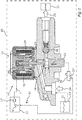
- Fig. 1 shows a motor vehicle 10 that can be, e.g., a passenger vehicle or a freight vehicle.
- the vehicle may comprise an internal combustion engine 11 that may be operated on the basis of fuel 12 from a fuel tank 13.
- the fuel 12 may be pumped from the fuel tank 13 to the combustion engine 11 by a pump 14.
- the pump 14 may comprise a switchable solenoid valve 15, e.g. a digital inlet valve, DIV, with a closing element or valve disk 16 and an electric coil or solenoid 18.
- An electric current I for the solenoid 18 may be controlled by an electronic circuit 17 that provides a control unit or controller 17' for switching the current I.
- the operation of the valve 15 can be coordinated with the rotation of a crank 20 by measuring a crank angle 21 and switching current I according to crank angle 21.
- Crank angle 21 may be measured using a sensor 21'.
- Crank 20 moves a piston 21 for a pumping movement 23 for pumping the fuel 12 from a low pressure side 24 to a high-pressure side 25 where the fuel is injected by a fuel injection system.
- Outlet valve 26 may be a passive valve, e.g. a check valve, wherein the inlet valve is provided by the solenoid valve 15 with its valve disk 16.
- current I is driven through solenoid 18 such that a pin 27 that holds the valve disk 16 is attracted against a spring force of a spring 28 towards a pole piece 29 and an armature such that valve disk 16 is moved from an open position 31 to a closed position 32.
- Current I may be provided by a voltage source U.
- Fig. 2 shows a current strength signal 33 of current I over time t or over crank angle 21 (CRK).
- a peak current 36 is provided that delivers an overall actuation energy for moving valve disk 16 from the open position 31 to the closed position 32.
- a hold phase 37 follows with a hold current 38.
- an opening phase O may follow in which current I is allowed to fall to zero such that spring 28 may open valve 16 again.
- Controller 17' controls current I during closing phase 35 using a bang-bang control method by switching on the voltage source U, if the value of current I is smaller than a lower threshold value 39, and switching off voltage source U, if the value of current I is greater than an upper threshold value 40.
- Electronic circuit 17 may measure a time difference 41 between e.g. two consecutive peaks 42 of the signal 33.
- the inverse value of time difference 41 yields a switching frequency F, i.e. the frequency or rate at which controller 17' switches current I.
- the switching frequency F is dependent on the induction value of the magnetic system of solenoid 18 and the magnetic materials and their position within pump 15. It is also dependent on the fact whether elements of the magnetic circuit of the valve 16 are in motion or not. In other words, the position and motion of valve disk 16 and pin 27 influences switching frequency F.
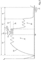
- Fig. 3 shows, how this can be used to detect the switching point SP during closing phase 35.
- MS of the switching frequency F (measurement N, N+1, N+2, N+3)
- the switching frequency may vary due to the changing position of the valve disk 16 and pin 27.
- Fig. 3 shows that measurement 43 (N+2) yields a switching frequency F where a change of the value of the induction of the magnetic circle results and a relative change 44 of the switching frequency F from the preceding measurement 45 (N+1) to measurement N+2 is greater than a predefined threshold value 46.
- Threshold value 46 is a closed position criterion that is fulfilled in measurement N+2. In other word, switching point SP is reached.
- the example shows how the invention provides method for detecting a switching point of a switchable solenoid valve.
Landscapes
- Engineering & Computer Science (AREA)
- Chemical & Material Sciences (AREA)
- Combustion & Propulsion (AREA)
- Mechanical Engineering (AREA)
- General Engineering & Computer Science (AREA)
- Fuel-Injection Apparatus (AREA)
- Electrical Control Of Air Or Fuel Supplied To Internal-Combustion Engine (AREA)
Abstract
Description
- The invention is concerned with a method for detecting a switching point of a switchable solenoid valve. The switching point is the time point at which the valve reaches a closing state during a closing phase. The invention is also directed to an electronic circuit for controlling a switchable solenoid valve. The invention also comprises a pump for an injection system of a motor vehicle and a motor vehicle comprising the injection system.
- One of the most used actuators for controlling the flow of a fluid is the solenoid valve. There are two main types of solenoid valves, the proportional valve and the digital valve. As an example, in diesel and gasoline common rail fuel injection systems, the rail pressure can be controlled by a digital inlet valve (DIV).
- The DIV is a solenoid valve which closes the inlet valve when it is energized, i.e. when an electric current is driven through the solenoid of the valve for closing the valve against a force of a spring. During a current-less state, the valve will open and be kept in open position by the DIV spring until the solenoid is energized again. The current profile for the DIV is a peak current and a hold current control. The peak current provides an actuation energy for moving the valve from the open position into the closed position. The hold current generates the magnetic field for keeping the valve in the closed position.
-
US 2012/0167993 A1 describes a method for reducing a noise generated when closing the inlet valve of a fuel pressure system. The duration of the peak current for providing the actuation energy is varied. However, this method implies that it is known, how far the acceleration or in general the actuation energy may be reduced without causing a failure of the actuation. -
US 8 245 693 B2 describes a method for reducing the noise in the closing state of an inlet valve of a high pressure injection system by reducing the amplitude of the peak current and at the same time letting the peak current flow for a longer time such that the velocity of the accelerated valve is reduced. This slows the pump down. - The switch time of the valve is a vital information for the precise fuel metering of a DIV. The pump delivery is varied by changing the closing position or switch point of the valve relative to the pump top dead center (TDC). This is illustrated in
Fig. 4. Fig. 4 provides two diagrams. One diagram shows the movement of the piston of the valve, i.e. the piston lift PL over time t. The other diagram shows the current profile of a current I that is applied to the solenoid current. The piston may be driven by a crank such that instead of measuring time t, the crank angle may be used to describe the position of the piston. The piston moves between the top dead center TDC and the bottom dead center BDC. The example shown inFig. 4 provides two full piston movements from TDC to TDC within a 360° turn of the crank. In other words, one pump cycle or actuation cycle or stroke (STRK) is performed within 180° crank angle (180° CRK). Within one actuation cycle, the pump performs a suction phase SUC, a refluxing phase RFLX and a pumping phase PMP. For switching from the refluxing phase to the pumping phase, the valve is actuated by driving the electric current I through the solenoid of the valve, wherein the actuation is achieved by the peak current IP and (after the valve has reached the switching point SP, at which the valve reaches the closed state) the electric current I may be reduced to a hold current IH. For opening the valve again, the current I is switched off, such that a spring may open the valve, once the pressure of the fuel inside the pump is low enough. - In order to have the valve close precisely at the required position or switching point SP, the electronic circuit providing the control unit needs to know how long the valve needs to reach its closed position, i.e. the switching point SP, once the peak current IP is started at a current begin B. This duration from current begin B until the switching point SP, at which the valve is completely closed for the first time, is the switch time T of the valve.
- The switch time T of valves can be different due to production tolerances, e.g. two valves show a different switch time T although both are having the same boundary conditions. Moreover, the switch time T can also be influenced by other boundary conditions, e.g. battery voltage and/or engine speed.
- Without knowing the switch time T of the valve, the pump delivery can deviate from the required fuel delivery in a fuel injection system. Although this might still be compensated by the control unit in a steady operating point, in dynamic operating points or dynamic boundary conditions, i.e. extreme conditions, this could lead to a bad fuel pressure control performance. Moreover, if the switch time assumed by the control unit is different from the real switch time T, small fuel quantity delivery and full load ability could be negatively influenced.
- Besides for the precise fuel delivery, the switch time T is also an important parameter to be controlled at the production end-of-line (EOL). A certain minimum and maximum tolerance range is defined at the EOL to ensure the quality of DIVs produced. Without knowing the actual switch time T of the DIVs, it is impossible to maintain the quality of the valves produced.
- It is an object of the present invention, to provide means for detecting a switching point of a solenoid valve.
- The object is solved by the subject matter of the independent claims. Additional aspects of the invention are described by the dependent claims, the following description and the figures.
- The invention provides a method for detecting a switching point of a switchable solenoid valve, particularly a digitally solenoid valve. In a closing phase of an actuation cycle of the valve, an electric current is driven through the electric coil or solenoid of the valve for generating a closing movement of the valve. The closing phase is the phase during which the peak current is applied as described. The closing phase moves a valve disk or in general a closing element of the valve from an open position to a closed position against a force of a spring until the switching point is reached, i.e. the time point at which the valve finally reaches the closed state. In a valve, the current increase of the peak current can be so fast that the current has to be limited to such a current level that can be accepted by the control unit. This is achieved by a two point current control or bang-bang closed-loop current control. In other words, during the closing phase, a control unit or controller controls the current strength value of the electric current by switching on a voltage source, if the value is smaller than a lower threshold value, and switching off the voltage source, if the value is greater than an upper threshold value. Switching off the voltage source means that the solenoid is disconnected from the voltage source such that an increase of the current is prevented. However, the current may continue flowing due to the induction of the electric circuit, especially the solenoid. To this end, a freewheeling diode may be provided.
- For detecting the switching point, a switching frequency at which the controller switches the voltage source on and off is determined and if the switching frequency fulfills a predefined closed state criterion, a signal is generated, wherein the signal signals that the valve reached the switching point. In other words, a change of current control frequency of the controller in the closing phase is detected. The current strength or the dynamic change of the current strength or the current level during closing phase is controlled via the described to point control method or bang-bang closed current control. It includes an upper current threshold value and a hysteresis, which results in the lower threshold value. By observing the current frequency during the bang-bang current control, a significant change in control frequency is detected at the switch point when the valve reaches its closed position.
- The frequency is mainly influenced by the current gradient which is dependent on the circuit induction. During the closing phase, the valve (i.e. its closing element) is accelerated from its open position towards its closed position. In other words, the closing element or valve disk moves towards the solenoid, as it is attracted by the magnetic force of the solenoid. The pole distance is getting smaller as the valve is approaching the closed position. This has an influence on the circuit induction. A change in current gradient is however not only due to the change in pole distance of the magnetic poles, but also due to the sudden stop of the movement of the valve, when the closed position is hit or reached. Before the valve reaches its closed position, the valve is in a state of movement. The movement of the valve also has an impact on the current gradient, i.e. it slows the current change down. This effect stops, once the closed position is reached. This can be used as a feedback to detect the switching point. The necessary degree of relative change can be defined by the said closed state criterion. The closed state criterion can be derived by simple experiments.
- The invention also comprises further aspects that provide additional technical advantages.
- The described method is a core element that can be used for several different applications. One application is the measurement of the described switch time. To this end, switching point data can be generated to describe the switching point as a time duration that is measured starting from a predefined starting point and ending at the switching point. The starting point may be the described current begin B or e.g. the TDC or the BDC of the piston lift. As was already explained, alternatively or additionally to defining a time duration, a relative change of a rotation angle or crank angle of a crank that drives the piston of the valve can be measured. Again, the relative change of rotation angle is measured starting from the predefined starting point and ending at the switching point. The switching point data thus describe the switch time T of the valve.
- The switching point data can be saved in an electronic circuit of the controller or control unit of the valve for controlling future closing phases on the basis of the switching point data. In other words, the switching point data can be used to calibrate the electronic circuit of the valve.
- The switching point data can be determined during an End-of-line calibration procedure after producing the valve. As was already described, this allows to individually calibrate each valve. Additionally or alternatively, the switching point data may be determined during a self-calibration procedure after the valve has been used for at least a predefined amount of time. As a valve changes its mechanical and/or magnetic and/or electric behavior during its lifetime, this allows for adapting the switching point data during operation of the valve. The described predetermined amount of time can be more than one week, especially more than one year.
- The closed state criterion that is used to detect the switching point may comprise that the switching frequency that results during the closing phase is above a predefined frequency threshold. In other words, an absolute value can be provided and the switching frequency is compared to this absolute value. Additionally or alternatively a relative or absolute change of the switching frequency compared to a switching frequency of a preceding actuation cycle may be detected and the closed state criterion may comprise that this relative or absolute change is greater than a predefined change threshold value. In other words, a step or jump of the switching frequency is detected with regard to a preceding actuation cycle. Determining the relative change provides the advantage that the method does not have to be adapted to a value of the switching frequency that is applied by the controller in the case that the valve is not closed yet.
- For measuring the switching frequency, one aspect of the invention comprises sensing a current strength signal of the electric current and determining a time difference between at least two predefined characteristic points of the signal. For example, a time difference between peaks of the signal can be measured or determined. This can be repeated for each measurement.
- As was already explained, the method is especially useful for calibrating a high-pressure pump of a fuel injection system of a motor vehicle. Correspondingly, as the valve an inlet valve of the high-pressure pump of the injection system of the motor vehicle is controlled. "High-pressure" especially means that the pump generates a pressure greater than 100 bar.
- For performing the inventive method, the invention also provides an electronic circuit for controlling a switchable solenoid valve. The electronic circuit is designed to perform an embodiment of the inventive method as described. The electronic circuit may comprise a microcontroller or a microprocessor for performing the steps of the method. The electronic circuit may provide said controller.
- The invention also comprises a pump for a fuel injection system of a motor vehicle, wherein the pump comprises the described switchable solenoid valve, particularly a digital inlet valve, and an embodiment of the inventive electronic circuit.
- Finally, the invention is concerned with a motor vehicle comprising an internal combustion engine with an injection system. The vehicle provides an injection system that comprises an embodiment of the inventive pump with the described electronic circuit.
- In the following an exemplary implementation of the invention is described. The figures show:
- Fig. 1
- a schematic illustration of an embodiment of the inventive motor vehicle;
- Fig. 2
- a diagram illustrating a current strength signal of an electric current of a solenoid of a pump of the motor vehicle of
Fig. 1 ; - Fig. 3
- a diagram illustrating a switching frequency of a controller of a valve of the pump; and
- Fig. 4
- a diagram illustrating the switch time of the valve.
- The embodiment explained in the following is a preferred embodiment of the invention. However, in the embodiment, the described components of the embodiment each represent individual features of the invention which are to be considered independently of each other and which each develop the invention also independently of each other and thereby are also to be regarded as a component of the invention in individual manner or in another than the shown combination. Furthermore, the described embodiment can also be supplemented by further features of the invention already described.
- In the figures elements that provide the same function are marked with identical reference signs.
-
Fig. 1 shows amotor vehicle 10 that can be, e.g., a passenger vehicle or a freight vehicle. The vehicle may comprise aninternal combustion engine 11 that may be operated on the basis offuel 12 from afuel tank 13. Thefuel 12 may be pumped from thefuel tank 13 to thecombustion engine 11 by apump 14. Thepump 14 may comprise aswitchable solenoid valve 15, e.g. a digital inlet valve, DIV, with a closing element orvalve disk 16 and an electric coil orsolenoid 18. An electric current I for thesolenoid 18 may be controlled by anelectronic circuit 17 that provides a control unit or controller 17' for switching the current I. The operation of thevalve 15 can be coordinated with the rotation of a crank 20 by measuring acrank angle 21 and switching current I according to crankangle 21. Crankangle 21 may be measured using a sensor 21'. Crank 20 moves apiston 21 for apumping movement 23 for pumping thefuel 12 from alow pressure side 24 to a high-pressure side 25 where the fuel is injected by a fuel injection system.Outlet valve 26 may be a passive valve, e.g. a check valve, wherein the inlet valve is provided by thesolenoid valve 15 with itsvalve disk 16. For closing thevalve 15, current I is driven throughsolenoid 18 such that apin 27 that holds thevalve disk 16 is attracted against a spring force of aspring 28 towards apole piece 29 and an armature such thatvalve disk 16 is moved from anopen position 31 to a closed position 32. Current I may be provided by a voltage source U. - Switching off voltage source U results in an exponential decrease of current I. Once the spring force of the
spring 28 is stronger than the magnetic field ofsolenoid 18, thevalve 16 is moved back from closed position 32 to openposition 31. This completes a full actuation cycle or pump cycle. -
Fig. 2 shows acurrent strength signal 33 of current I over time t or over crank angle 21 (CRK). During a pump cycle oractuation cycle 34 during an closing phase 35 a peak current 36 is provided that delivers an overall actuation energy for movingvalve disk 16 from theopen position 31 to the closed position 32. Oncevalve disk 16 is in closed position 32, ahold phase 37 follows with ahold current 38. After holdingphase 37 an opening phase O may follow in which current I is allowed to fall to zero such thatspring 28 may openvalve 16 again. - Controller 17' controls current I during closing
phase 35 using a bang-bang control method by switching on the voltage source U, if the value of current I is smaller than alower threshold value 39, and switching off voltage source U, if the value of current I is greater than anupper threshold value 40. -
Electronic circuit 17 may measure atime difference 41 between e.g. twoconsecutive peaks 42 of thesignal 33. The inverse value oftime difference 41 yields a switching frequency F, i.e. the frequency or rate at which controller 17' switches current I. The switching frequency F is dependent on the induction value of the magnetic system ofsolenoid 18 and the magnetic materials and their position withinpump 15. It is also dependent on the fact whether elements of the magnetic circuit of thevalve 16 are in motion or not. In other words, the position and motion ofvalve disk 16 and pin 27 influences switching frequency F. -
Fig. 3 shows, how this can be used to detect the switching point SP during closingphase 35. During several consecutive measurements MS of the switching frequency F (measurement N, N+1, N+2, N+3), the switching frequency may vary due to the changing position of thevalve disk 16 andpin 27.Fig. 3 shows that measurement 43 (N+2) yields a switching frequency F where a change of the value of the induction of the magnetic circle results and a relative change 44 of the switching frequency F from the preceding measurement 45 (N+1) tomeasurement N+ 2 is greater than apredefined threshold value 46.Threshold value 46 is a closed position criterion that is fulfilled inmeasurement N+ 2. In other word, switching point SP is reached. - Thus the time point or the crank angle at this parameter value used for generating switching point data that may describe the switch time T.
- Thus, by measuring the control frequency or switching frequency before and after the switching point, a difference can be detected. This is a low-cost strategy to detect the switch point of a solenoid valve, especially a digital solenoid valve.
- Overall, the example shows how the invention provides method for detecting a switching point of a switchable solenoid valve.
Claims (10)
- Method for detecting a switching point of a switchable solenoid valve (15), wherein in a closing phase of the valve (15) an electric current (I) is driven through the solenoid (18) of the valve (15) for generating a closing movement of (a valve disk or a closing element of) the valve (15) against a force of a spring (28) until a switching point is reached (time point) at which the valve (15) finally reaches a closed state, wherein during the closing phase (37) a controller (17') controls a current strength value of the electric current (I) by switching on a voltage source (U), if the value is smaller than a lower threshold value (39), and switching off the voltage source (U), if the value is greater than an upper threshold value (40), characterized in that for detecting the switching point a switching frequency (F) at which the controller (17') switches the voltage source (U) is determined and if the switching frequency (F) fulfills a predefined closed state criterion (46), a signal is generated, wherein the signal signals that the valve (15) reached the switching point.
- Method according to claim 1, wherein switching point data are generated that describe the switching point as a time duration and/or a relative change of a rotation angle of a crank that drives a piston of the valve (15), wherein the time duration and/or the relative change of rotation angle is measured starting from a predefined starting point and ending at the switching point.
- Method according to claims 2, wherein the switching point data are saved in an electronic circuit (17) of the valve (15) for controlling future closing phases on the basis of the switching point data.
- Method according to one of claims 2 or 3, wherein the switching point data are determined during an end-of-line calibration procedure after producing the valve (15) and/or during a self-calibration procedure after the valve has been used for at least a predefined amount of time.
- Method according to any of the preceding claims, wherein the closed state criterion (46) comprises that the switching frequency (F) is above a predefined frequency threshold value and/or that the switching frequency (F) changes by a relative or absolute change (44) greater than a predefined change threshold value (46).
- Method according to any of the preceding claims, wherein the switching frequency (F) is measured by sensing a current strength signal (33) of the electric current (I) and determining a time difference (41) between at least two predefined characteristic points (42) of the signal (33).
- Method according to any of the preceding claims, wherein as the valve (15) an inlet valve of a high pressure pump (14) of an injection system of a motor vehicle (10) is controlled.
- Electronic circuit (17) for controlling a switchable solenoid valve (15), wherein the electronic circuit (17) is designed to perform a method according to any of the preceding claims.
- Pump (14) for an injection system of a motor vehicle (10), wherein the pump (14) comprises a switchable solenoid valve (15) and an electronic circuit (17) according to claim 8.
- Motor vehicle (10) comprising an internal combustion engine (11) with a fuel injection system that provides a pump (14) according to claim 9.
Priority Applications (1)
| Application Number | Priority Date | Filing Date | Title |
|---|---|---|---|
| EP17165234.0A EP3385528B1 (en) | 2017-04-06 | 2017-04-06 | Method for detecting a switching point of a switchable solenoid valve, electronic circuit, pump and motor vehicle |
Applications Claiming Priority (1)
| Application Number | Priority Date | Filing Date | Title |
|---|---|---|---|
| EP17165234.0A EP3385528B1 (en) | 2017-04-06 | 2017-04-06 | Method for detecting a switching point of a switchable solenoid valve, electronic circuit, pump and motor vehicle |
Publications (2)
| Publication Number | Publication Date |
|---|---|
| EP3385528A1 true EP3385528A1 (en) | 2018-10-10 |
| EP3385528B1 EP3385528B1 (en) | 2020-10-28 |
Family
ID=58547327
Family Applications (1)
| Application Number | Title | Priority Date | Filing Date |
|---|---|---|---|
| EP17165234.0A Active EP3385528B1 (en) | 2017-04-06 | 2017-04-06 | Method for detecting a switching point of a switchable solenoid valve, electronic circuit, pump and motor vehicle |
Country Status (1)
| Country | Link |
|---|---|
| EP (1) | EP3385528B1 (en) |
Cited By (3)
| Publication number | Priority date | Publication date | Assignee | Title |
|---|---|---|---|---|
| EP3712418A1 (en) * | 2019-03-20 | 2020-09-23 | Vitesco Technologies GmbH | Method for operating a pressure control valve, method for operating a fluid supply system and device for operating a fluid supply system |
| US11476028B2 (en) | 2020-01-10 | 2022-10-18 | Ford Global Technologies, Llc | 219-1040 method for driving inductive peak and hold loads at reduced power |
| CN118517457A (en) * | 2024-05-30 | 2024-08-20 | 三一重机有限公司 | Method, device, computer equipment and storage medium for adjusting state switching of hydraulic motor |
Families Citing this family (1)
| Publication number | Priority date | Publication date | Assignee | Title |
|---|---|---|---|---|
| DE102020213203A1 (en) * | 2020-10-20 | 2022-04-21 | Robert Bosch Gesellschaft mit beschränkter Haftung | Method for determining a switching time of a solenoid valve |
Citations (9)
| Publication number | Priority date | Publication date | Assignee | Title |
|---|---|---|---|---|
| US5053911A (en) * | 1989-06-02 | 1991-10-01 | Motorola, Inc. | Solenoid closure detection |
| DE4237706A1 (en) * | 1992-11-07 | 1994-05-11 | Mtu Friedrichshafen Gmbh | Circuit to determine response end point of solenoid armature of valve - has pulsed excitation of coil with change in mark to space ratio used to identify response end point |
| US5375575A (en) * | 1992-03-26 | 1994-12-27 | Zexel Corporation | Fuel-injection device |
| US5592921A (en) * | 1993-12-08 | 1997-01-14 | Robert Bosch Gmbh | Method and device for actuating an electromagnetic load |
| US5835330A (en) * | 1994-06-10 | 1998-11-10 | Robert Bosch Gmbh | Method and device for driving an electromagnetic consumer |
| EP2116709A1 (en) * | 2008-05-08 | 2009-11-11 | Perkins Engines Company Limited | Indication of a solenoid temperature change |
| US20110149458A1 (en) * | 2009-12-17 | 2011-06-23 | Caterpillar Inc. | Systems and methods for detecting solenoid armature movement |
| US20120167993A1 (en) | 2010-12-30 | 2012-07-05 | Delphi Technologies, Inc. | Fuel pressure control system and method having a variable pull-in time interval based pressure |
| US8245693B2 (en) | 2008-12-08 | 2012-08-21 | Ford Global Technologies, Llc | High pressure fuel pump control for idle tick reduction |
Family Cites Families (1)
| Publication number | Priority date | Publication date | Assignee | Title |
|---|---|---|---|---|
| JP6244723B2 (en) * | 2013-08-02 | 2017-12-13 | 株式会社デンソー | High pressure pump control device |
-
2017
- 2017-04-06 EP EP17165234.0A patent/EP3385528B1/en active Active
Patent Citations (9)
| Publication number | Priority date | Publication date | Assignee | Title |
|---|---|---|---|---|
| US5053911A (en) * | 1989-06-02 | 1991-10-01 | Motorola, Inc. | Solenoid closure detection |
| US5375575A (en) * | 1992-03-26 | 1994-12-27 | Zexel Corporation | Fuel-injection device |
| DE4237706A1 (en) * | 1992-11-07 | 1994-05-11 | Mtu Friedrichshafen Gmbh | Circuit to determine response end point of solenoid armature of valve - has pulsed excitation of coil with change in mark to space ratio used to identify response end point |
| US5592921A (en) * | 1993-12-08 | 1997-01-14 | Robert Bosch Gmbh | Method and device for actuating an electromagnetic load |
| US5835330A (en) * | 1994-06-10 | 1998-11-10 | Robert Bosch Gmbh | Method and device for driving an electromagnetic consumer |
| EP2116709A1 (en) * | 2008-05-08 | 2009-11-11 | Perkins Engines Company Limited | Indication of a solenoid temperature change |
| US8245693B2 (en) | 2008-12-08 | 2012-08-21 | Ford Global Technologies, Llc | High pressure fuel pump control for idle tick reduction |
| US20110149458A1 (en) * | 2009-12-17 | 2011-06-23 | Caterpillar Inc. | Systems and methods for detecting solenoid armature movement |
| US20120167993A1 (en) | 2010-12-30 | 2012-07-05 | Delphi Technologies, Inc. | Fuel pressure control system and method having a variable pull-in time interval based pressure |
Cited By (3)
| Publication number | Priority date | Publication date | Assignee | Title |
|---|---|---|---|---|
| EP3712418A1 (en) * | 2019-03-20 | 2020-09-23 | Vitesco Technologies GmbH | Method for operating a pressure control valve, method for operating a fluid supply system and device for operating a fluid supply system |
| US11476028B2 (en) | 2020-01-10 | 2022-10-18 | Ford Global Technologies, Llc | 219-1040 method for driving inductive peak and hold loads at reduced power |
| CN118517457A (en) * | 2024-05-30 | 2024-08-20 | 三一重机有限公司 | Method, device, computer equipment and storage medium for adjusting state switching of hydraulic motor |
Also Published As
| Publication number | Publication date |
|---|---|
| EP3385528B1 (en) | 2020-10-28 |
Similar Documents
| Publication | Publication Date | Title |
|---|---|---|
| EP3385528B1 (en) | Method for detecting a switching point of a switchable solenoid valve, electronic circuit, pump and motor vehicle | |
| JP5534496B2 (en) | Control device for solenoid valve | |
| EP2721331B1 (en) | Method of monitoring a solenoid-operated valve | |
| CN103635680B (en) | Method and apparatus for running automotive fuel conveying equipment | |
| US20120000445A1 (en) | Method and Control Apparatus for Controlling a High-Pressure Fuel Supply Pump | |
| CN103119271B (en) | Determination of the ballistic trajectory of an electromagnetically driven armature of a coil actuator | |
| EP3417162A1 (en) | Detection of valve open time for solenoid operated fuel injectors | |
| CN103649521A (en) | Valve control method and device | |
| CN110541769A (en) | Method for determining the closing moment of an electromagnetic fuel injector | |
| CN105089891A (en) | Direct injection pump control for low fuel pumping volumes | |
| WO2017022479A1 (en) | Control device of fuel injection device | |
| US10731591B2 (en) | Pressure sensor of a high-pressure injection system, control device, high-pressure injection system, and motor vehicle | |
| KR101974297B1 (en) | Method and apparatus for determining the stroke of an armature, method for operating a magnetic valve | |
| JP7330759B2 (en) | How to Determine the Rise Time of an Electromagnetic Fuel Injector | |
| JP6835960B2 (en) | Methods, controls, high pressure injection systems, and automobiles for checking the calibration of pressure sensors in automobile injection systems. | |
| CN109863292B (en) | Method for operating a high-pressure pump of a high-pressure injection system of a motor vehicle, control device and motor vehicle | |
| EP3385527B1 (en) | Method for detecting a failed actuation of a switchable solenoid valve, electronic circuit for performing the method, pump and motor vehicle | |
| US11078877B2 (en) | Method for switching a current in an electromagnet of a switchable solenoid valve, electronic circuit, solenoid valve, pump, and motor vehicle | |
| JP2010059860A (en) | Fuel injection device for internal combustion engine | |
| JP6519669B2 (en) | Control device for high pressure pump | |
| US11719264B2 (en) | Method for ascertaining the movement of an armature of an electric intake valve | |
| US10473077B2 (en) | Control device for high-pressure pump | |
| JP2016191341A (en) | Pump control device |
Legal Events
| Date | Code | Title | Description |
|---|---|---|---|
| PUAI | Public reference made under article 153(3) epc to a published international application that has entered the european phase |
Free format text: ORIGINAL CODE: 0009012 |
|
| STAA | Information on the status of an ep patent application or granted ep patent |
Free format text: STATUS: THE APPLICATION HAS BEEN PUBLISHED |
|
| AK | Designated contracting states |
Kind code of ref document: A1 Designated state(s): AL AT BE BG CH CY CZ DE DK EE ES FI FR GB GR HR HU IE IS IT LI LT LU LV MC MK MT NL NO PL PT RO RS SE SI SK SM TR |
|
| AX | Request for extension of the european patent |
Extension state: BA ME |
|
| STAA | Information on the status of an ep patent application or granted ep patent |
Free format text: STATUS: REQUEST FOR EXAMINATION WAS MADE |
|
| 17P | Request for examination filed |
Effective date: 20190410 |
|
| RBV | Designated contracting states (corrected) |
Designated state(s): AL AT BE BG CH CY CZ DE DK EE ES FI FR GB GR HR HU IE IS IT LI LT LU LV MC MK MT NL NO PL PT RO RS SE SI SK SM TR |
|
| STAA | Information on the status of an ep patent application or granted ep patent |
Free format text: STATUS: EXAMINATION IS IN PROGRESS |
|
| 17Q | First examination report despatched |
Effective date: 20191104 |
|
| RAP1 | Party data changed (applicant data changed or rights of an application transferred) |
Owner name: VITESCO TECHNOLOGIES GMBH |
|
| GRAP | Despatch of communication of intention to grant a patent |
Free format text: ORIGINAL CODE: EPIDOSNIGR1 |
|
| STAA | Information on the status of an ep patent application or granted ep patent |
Free format text: STATUS: GRANT OF PATENT IS INTENDED |
|
| INTG | Intention to grant announced |
Effective date: 20200703 |
|
| GRAS | Grant fee paid |
Free format text: ORIGINAL CODE: EPIDOSNIGR3 |
|
| GRAA | (expected) grant |
Free format text: ORIGINAL CODE: 0009210 |
|
| STAA | Information on the status of an ep patent application or granted ep patent |
Free format text: STATUS: THE PATENT HAS BEEN GRANTED |
|
| AK | Designated contracting states |
Kind code of ref document: B1 Designated state(s): AL AT BE BG CH CY CZ DE DK EE ES FI FR GB GR HR HU IE IS IT LI LT LU LV MC MK MT NL NO PL PT RO RS SE SI SK SM TR |
|
| REG | Reference to a national code |
Ref country code: GB Ref legal event code: FG4D |
|
| REG | Reference to a national code |
Ref country code: CH Ref legal event code: EP |
|
| REG | Reference to a national code |
Ref country code: DE Ref legal event code: R096 Ref document number: 602017026171 Country of ref document: DE |
|
| REG | Reference to a national code |
Ref country code: AT Ref legal event code: REF Ref document number: 1328471 Country of ref document: AT Kind code of ref document: T Effective date: 20201115 |
|
| REG | Reference to a national code |
Ref country code: IE Ref legal event code: FG4D |
|
| REG | Reference to a national code |
Ref country code: AT Ref legal event code: MK05 Ref document number: 1328471 Country of ref document: AT Kind code of ref document: T Effective date: 20201028 |
|
| REG | Reference to a national code |
Ref country code: NL Ref legal event code: MP Effective date: 20201028 |
|
| PG25 | Lapsed in a contracting state [announced via postgrant information from national office to epo] |
Ref country code: GR Free format text: LAPSE BECAUSE OF FAILURE TO SUBMIT A TRANSLATION OF THE DESCRIPTION OR TO PAY THE FEE WITHIN THE PRESCRIBED TIME-LIMIT Effective date: 20210129 Ref country code: FI Free format text: LAPSE BECAUSE OF FAILURE TO SUBMIT A TRANSLATION OF THE DESCRIPTION OR TO PAY THE FEE WITHIN THE PRESCRIBED TIME-LIMIT Effective date: 20201028 Ref country code: NO Free format text: LAPSE BECAUSE OF FAILURE TO SUBMIT A TRANSLATION OF THE DESCRIPTION OR TO PAY THE FEE WITHIN THE PRESCRIBED TIME-LIMIT Effective date: 20210128 Ref country code: PT Free format text: LAPSE BECAUSE OF FAILURE TO SUBMIT A TRANSLATION OF THE DESCRIPTION OR TO PAY THE FEE WITHIN THE PRESCRIBED TIME-LIMIT Effective date: 20210301 Ref country code: RS Free format text: LAPSE BECAUSE OF FAILURE TO SUBMIT A TRANSLATION OF THE DESCRIPTION OR TO PAY THE FEE WITHIN THE PRESCRIBED TIME-LIMIT Effective date: 20201028 |
|
| REG | Reference to a national code |
Ref country code: LT Ref legal event code: MG4D |
|
| PG25 | Lapsed in a contracting state [announced via postgrant information from national office to epo] |
Ref country code: SE Free format text: LAPSE BECAUSE OF FAILURE TO SUBMIT A TRANSLATION OF THE DESCRIPTION OR TO PAY THE FEE WITHIN THE PRESCRIBED TIME-LIMIT Effective date: 20201028 Ref country code: ES Free format text: LAPSE BECAUSE OF FAILURE TO SUBMIT A TRANSLATION OF THE DESCRIPTION OR TO PAY THE FEE WITHIN THE PRESCRIBED TIME-LIMIT Effective date: 20201028 Ref country code: AT Free format text: LAPSE BECAUSE OF FAILURE TO SUBMIT A TRANSLATION OF THE DESCRIPTION OR TO PAY THE FEE WITHIN THE PRESCRIBED TIME-LIMIT Effective date: 20201028 Ref country code: BG Free format text: LAPSE BECAUSE OF FAILURE TO SUBMIT A TRANSLATION OF THE DESCRIPTION OR TO PAY THE FEE WITHIN THE PRESCRIBED TIME-LIMIT Effective date: 20210128 Ref country code: LV Free format text: LAPSE BECAUSE OF FAILURE TO SUBMIT A TRANSLATION OF THE DESCRIPTION OR TO PAY THE FEE WITHIN THE PRESCRIBED TIME-LIMIT Effective date: 20201028 Ref country code: IS Free format text: LAPSE BECAUSE OF FAILURE TO SUBMIT A TRANSLATION OF THE DESCRIPTION OR TO PAY THE FEE WITHIN THE PRESCRIBED TIME-LIMIT Effective date: 20210228 Ref country code: PL Free format text: LAPSE BECAUSE OF FAILURE TO SUBMIT A TRANSLATION OF THE DESCRIPTION OR TO PAY THE FEE WITHIN THE PRESCRIBED TIME-LIMIT Effective date: 20201028 |
|
| PG25 | Lapsed in a contracting state [announced via postgrant information from national office to epo] |
Ref country code: NL Free format text: LAPSE BECAUSE OF FAILURE TO SUBMIT A TRANSLATION OF THE DESCRIPTION OR TO PAY THE FEE WITHIN THE PRESCRIBED TIME-LIMIT Effective date: 20201028 Ref country code: HR Free format text: LAPSE BECAUSE OF FAILURE TO SUBMIT A TRANSLATION OF THE DESCRIPTION OR TO PAY THE FEE WITHIN THE PRESCRIBED TIME-LIMIT Effective date: 20201028 |
|
| REG | Reference to a national code |
Ref country code: DE Ref legal event code: R097 Ref document number: 602017026171 Country of ref document: DE |
|
| PG25 | Lapsed in a contracting state [announced via postgrant information from national office to epo] |
Ref country code: EE Free format text: LAPSE BECAUSE OF FAILURE TO SUBMIT A TRANSLATION OF THE DESCRIPTION OR TO PAY THE FEE WITHIN THE PRESCRIBED TIME-LIMIT Effective date: 20201028 Ref country code: CZ Free format text: LAPSE BECAUSE OF FAILURE TO SUBMIT A TRANSLATION OF THE DESCRIPTION OR TO PAY THE FEE WITHIN THE PRESCRIBED TIME-LIMIT Effective date: 20201028 Ref country code: LT Free format text: LAPSE BECAUSE OF FAILURE TO SUBMIT A TRANSLATION OF THE DESCRIPTION OR TO PAY THE FEE WITHIN THE PRESCRIBED TIME-LIMIT Effective date: 20201028 Ref country code: SM Free format text: LAPSE BECAUSE OF FAILURE TO SUBMIT A TRANSLATION OF THE DESCRIPTION OR TO PAY THE FEE WITHIN THE PRESCRIBED TIME-LIMIT Effective date: 20201028 Ref country code: SK Free format text: LAPSE BECAUSE OF FAILURE TO SUBMIT A TRANSLATION OF THE DESCRIPTION OR TO PAY THE FEE WITHIN THE PRESCRIBED TIME-LIMIT Effective date: 20201028 Ref country code: RO Free format text: LAPSE BECAUSE OF FAILURE TO SUBMIT A TRANSLATION OF THE DESCRIPTION OR TO PAY THE FEE WITHIN THE PRESCRIBED TIME-LIMIT Effective date: 20201028 |
|
| PG25 | Lapsed in a contracting state [announced via postgrant information from national office to epo] |
Ref country code: DK Free format text: LAPSE BECAUSE OF FAILURE TO SUBMIT A TRANSLATION OF THE DESCRIPTION OR TO PAY THE FEE WITHIN THE PRESCRIBED TIME-LIMIT Effective date: 20201028 |
|
| PLBE | No opposition filed within time limit |
Free format text: ORIGINAL CODE: 0009261 |
|
| STAA | Information on the status of an ep patent application or granted ep patent |
Free format text: STATUS: NO OPPOSITION FILED WITHIN TIME LIMIT |
|
| 26N | No opposition filed |
Effective date: 20210729 |
|
| PG25 | Lapsed in a contracting state [announced via postgrant information from national office to epo] |
Ref country code: IT Free format text: LAPSE BECAUSE OF FAILURE TO SUBMIT A TRANSLATION OF THE DESCRIPTION OR TO PAY THE FEE WITHIN THE PRESCRIBED TIME-LIMIT Effective date: 20201028 Ref country code: AL Free format text: LAPSE BECAUSE OF FAILURE TO SUBMIT A TRANSLATION OF THE DESCRIPTION OR TO PAY THE FEE WITHIN THE PRESCRIBED TIME-LIMIT Effective date: 20201028 |
|
| PG25 | Lapsed in a contracting state [announced via postgrant information from national office to epo] |
Ref country code: MC Free format text: LAPSE BECAUSE OF FAILURE TO SUBMIT A TRANSLATION OF THE DESCRIPTION OR TO PAY THE FEE WITHIN THE PRESCRIBED TIME-LIMIT Effective date: 20201028 Ref country code: SI Free format text: LAPSE BECAUSE OF FAILURE TO SUBMIT A TRANSLATION OF THE DESCRIPTION OR TO PAY THE FEE WITHIN THE PRESCRIBED TIME-LIMIT Effective date: 20201028 |
|
| PG25 | Lapsed in a contracting state [announced via postgrant information from national office to epo] |
Ref country code: LU Free format text: LAPSE BECAUSE OF NON-PAYMENT OF DUE FEES Effective date: 20210406 |
|
| REG | Reference to a national code |
Ref country code: DE Ref legal event code: R081 Ref document number: 602017026171 Country of ref document: DE Owner name: SCHAEFFLER TECHNOLOGIES AG & CO. KG, DE Free format text: FORMER OWNER: VITESCO TECHNOLOGIES GMBH, 30165 HANNOVER, DE Ref country code: DE Ref legal event code: R081 Ref document number: 602017026171 Country of ref document: DE Owner name: VITESCO TECHNOLOGIES GMBH, DE Free format text: FORMER OWNER: VITESCO TECHNOLOGIES GMBH, 30165 HANNOVER, DE |
|
| REG | Reference to a national code |
Ref country code: BE Ref legal event code: MM Effective date: 20210430 |
|
| PG25 | Lapsed in a contracting state [announced via postgrant information from national office to epo] |
Ref country code: LI Free format text: LAPSE BECAUSE OF NON-PAYMENT OF DUE FEES Effective date: 20210430 Ref country code: CH Free format text: LAPSE BECAUSE OF NON-PAYMENT OF DUE FEES Effective date: 20210430 |
|
| PG25 | Lapsed in a contracting state [announced via postgrant information from national office to epo] |
Ref country code: IE Free format text: LAPSE BECAUSE OF NON-PAYMENT OF DUE FEES Effective date: 20210406 |
|
| PG25 | Lapsed in a contracting state [announced via postgrant information from national office to epo] |
Ref country code: IS Free format text: LAPSE BECAUSE OF FAILURE TO SUBMIT A TRANSLATION OF THE DESCRIPTION OR TO PAY THE FEE WITHIN THE PRESCRIBED TIME-LIMIT Effective date: 20210228 |
|
| PG25 | Lapsed in a contracting state [announced via postgrant information from national office to epo] |
Ref country code: BE Free format text: LAPSE BECAUSE OF NON-PAYMENT OF DUE FEES Effective date: 20210430 |
|
| PG25 | Lapsed in a contracting state [announced via postgrant information from national office to epo] |
Ref country code: CY Free format text: LAPSE BECAUSE OF FAILURE TO SUBMIT A TRANSLATION OF THE DESCRIPTION OR TO PAY THE FEE WITHIN THE PRESCRIBED TIME-LIMIT Effective date: 20201028 |
|
| P01 | Opt-out of the competence of the unified patent court (upc) registered |
Effective date: 20230530 |
|
| PG25 | Lapsed in a contracting state [announced via postgrant information from national office to epo] |
Ref country code: HU Free format text: LAPSE BECAUSE OF FAILURE TO SUBMIT A TRANSLATION OF THE DESCRIPTION OR TO PAY THE FEE WITHIN THE PRESCRIBED TIME-LIMIT; INVALID AB INITIO Effective date: 20170406 |
|
| PG25 | Lapsed in a contracting state [announced via postgrant information from national office to epo] |
Ref country code: MK Free format text: LAPSE BECAUSE OF FAILURE TO SUBMIT A TRANSLATION OF THE DESCRIPTION OR TO PAY THE FEE WITHIN THE PRESCRIBED TIME-LIMIT Effective date: 20201028 |
|
| PG25 | Lapsed in a contracting state [announced via postgrant information from national office to epo] |
Ref country code: MT Free format text: LAPSE BECAUSE OF FAILURE TO SUBMIT A TRANSLATION OF THE DESCRIPTION OR TO PAY THE FEE WITHIN THE PRESCRIBED TIME-LIMIT Effective date: 20201028 |
|
| REG | Reference to a national code |
Ref country code: DE Ref legal event code: R081 Ref document number: 602017026171 Country of ref document: DE Owner name: SCHAEFFLER TECHNOLOGIES AG & CO. KG, DE Free format text: FORMER OWNER: VITESCO TECHNOLOGIES GMBH, 93055 REGENSBURG, DE |
|
| PG25 | Lapsed in a contracting state [announced via postgrant information from national office to epo] |
Ref country code: TR Free format text: LAPSE BECAUSE OF FAILURE TO SUBMIT A TRANSLATION OF THE DESCRIPTION OR TO PAY THE FEE WITHIN THE PRESCRIBED TIME-LIMIT Effective date: 20201028 |
|
| PGFP | Annual fee paid to national office [announced via postgrant information from national office to epo] |
Ref country code: GB Payment date: 20260423 Year of fee payment: 10 |
|
| PGFP | Annual fee paid to national office [announced via postgrant information from national office to epo] |
Ref country code: DE Payment date: 20260430 Year of fee payment: 10 |
|
| PGFP | Annual fee paid to national office [announced via postgrant information from national office to epo] |
Ref country code: FR Payment date: 20260420 Year of fee payment: 10 |