EP3385504A1 - Vane cooling system - Google Patents
Vane cooling system Download PDFInfo
- Publication number
- EP3385504A1 EP3385504A1 EP18160507.2A EP18160507A EP3385504A1 EP 3385504 A1 EP3385504 A1 EP 3385504A1 EP 18160507 A EP18160507 A EP 18160507A EP 3385504 A1 EP3385504 A1 EP 3385504A1
- Authority
- EP
- European Patent Office
- Prior art keywords
- vane
- inlet
- cooling system
- chamber
- side wall
- Prior art date
- Legal status (The legal status is an assumption and is not a legal conclusion. Google has not performed a legal analysis and makes no representation as to the accuracy of the status listed.)
- Granted
Links
Images




Classifications
-
- F—MECHANICAL ENGINEERING; LIGHTING; HEATING; WEAPONS; BLASTING
- F01—MACHINES OR ENGINES IN GENERAL; ENGINE PLANTS IN GENERAL; STEAM ENGINES
- F01D—NON-POSITIVE DISPLACEMENT MACHINES OR ENGINES, e.g. STEAM TURBINES
- F01D5/00—Blades; Blade-carrying members; Heating, heat-insulating, cooling or antivibration means on the blades or the members
- F01D5/12—Blades
- F01D5/14—Form or construction
- F01D5/18—Hollow blades, i.e. blades with cooling or heating channels or cavities; Heating, heat-insulating or cooling means on blades
- F01D5/186—Film cooling
-
- F—MECHANICAL ENGINEERING; LIGHTING; HEATING; WEAPONS; BLASTING
- F01—MACHINES OR ENGINES IN GENERAL; ENGINE PLANTS IN GENERAL; STEAM ENGINES
- F01D—NON-POSITIVE DISPLACEMENT MACHINES OR ENGINES, e.g. STEAM TURBINES
- F01D11/00—Preventing or minimising internal leakage of working-fluid, e.g. between stages
- F01D11/08—Preventing or minimising internal leakage of working-fluid, e.g. between stages for sealing space between rotor blade tips and stator
- F01D11/10—Preventing or minimising internal leakage of working-fluid, e.g. between stages for sealing space between rotor blade tips and stator using sealing fluid, e.g. steam
-
- F—MECHANICAL ENGINEERING; LIGHTING; HEATING; WEAPONS; BLASTING
- F01—MACHINES OR ENGINES IN GENERAL; ENGINE PLANTS IN GENERAL; STEAM ENGINES
- F01D—NON-POSITIVE DISPLACEMENT MACHINES OR ENGINES, e.g. STEAM TURBINES
- F01D11/00—Preventing or minimising internal leakage of working-fluid, e.g. between stages
- F01D11/08—Preventing or minimising internal leakage of working-fluid, e.g. between stages for sealing space between rotor blade tips and stator
- F01D11/14—Adjusting or regulating tip-clearance, i.e. distance between rotor-blade tips and stator casing
- F01D11/20—Actively adjusting tip-clearance
- F01D11/24—Actively adjusting tip-clearance by selectively cooling-heating stator or rotor components
-
- F—MECHANICAL ENGINEERING; LIGHTING; HEATING; WEAPONS; BLASTING
- F01—MACHINES OR ENGINES IN GENERAL; ENGINE PLANTS IN GENERAL; STEAM ENGINES
- F01D—NON-POSITIVE DISPLACEMENT MACHINES OR ENGINES, e.g. STEAM TURBINES
- F01D25/00—Component parts, details, or accessories, not provided for in, or of interest apart from, other groups
- F01D25/08—Cooling; Heating; Heat-insulation
- F01D25/12—Cooling
-
- F—MECHANICAL ENGINEERING; LIGHTING; HEATING; WEAPONS; BLASTING
- F01—MACHINES OR ENGINES IN GENERAL; ENGINE PLANTS IN GENERAL; STEAM ENGINES
- F01D—NON-POSITIVE DISPLACEMENT MACHINES OR ENGINES, e.g. STEAM TURBINES
- F01D9/00—Stators
- F01D9/02—Nozzles; Nozzle boxes; Stator blades; Guide conduits, e.g. individual nozzles
- F01D9/04—Nozzles; Nozzle boxes; Stator blades; Guide conduits, e.g. individual nozzles forming ring or sector
- F01D9/041—Nozzles; Nozzle boxes; Stator blades; Guide conduits, e.g. individual nozzles forming ring or sector using blades
-
- F—MECHANICAL ENGINEERING; LIGHTING; HEATING; WEAPONS; BLASTING
- F01—MACHINES OR ENGINES IN GENERAL; ENGINE PLANTS IN GENERAL; STEAM ENGINES
- F01D—NON-POSITIVE DISPLACEMENT MACHINES OR ENGINES, e.g. STEAM TURBINES
- F01D9/00—Stators
- F01D9/06—Fluid supply conduits to nozzles or the like
- F01D9/065—Fluid supply or removal conduits traversing the working fluid flow, e.g. for lubrication-, cooling-, or sealing fluids
-
- F—MECHANICAL ENGINEERING; LIGHTING; HEATING; WEAPONS; BLASTING
- F02—COMBUSTION ENGINES; HOT-GAS OR COMBUSTION-PRODUCT ENGINE PLANTS
- F02C—GAS-TURBINE PLANTS; AIR INTAKES FOR JET-PROPULSION PLANTS; CONTROLLING FUEL SUPPLY IN AIR-BREATHING JET-PROPULSION PLANTS
- F02C7/00—Features, components parts, details or accessories, not provided for in, or of interest apart form groups F02C1/00 - F02C6/00; Air intakes for jet-propulsion plants
- F02C7/12—Cooling of plants
- F02C7/16—Cooling of plants characterised by cooling medium
- F02C7/18—Cooling of plants characterised by cooling medium the medium being gaseous, e.g. air
-
- F—MECHANICAL ENGINEERING; LIGHTING; HEATING; WEAPONS; BLASTING
- F05—INDEXING SCHEMES RELATING TO ENGINES OR PUMPS IN VARIOUS SUBCLASSES OF CLASSES F01-F04
- F05D—INDEXING SCHEME FOR ASPECTS RELATING TO NON-POSITIVE-DISPLACEMENT MACHINES OR ENGINES, GAS-TURBINES OR JET-PROPULSION PLANTS
- F05D2240/00—Components
- F05D2240/10—Stators
- F05D2240/11—Shroud seal segments
-
- F—MECHANICAL ENGINEERING; LIGHTING; HEATING; WEAPONS; BLASTING
- F05—INDEXING SCHEMES RELATING TO ENGINES OR PUMPS IN VARIOUS SUBCLASSES OF CLASSES F01-F04
- F05D—INDEXING SCHEME FOR ASPECTS RELATING TO NON-POSITIVE-DISPLACEMENT MACHINES OR ENGINES, GAS-TURBINES OR JET-PROPULSION PLANTS
- F05D2240/00—Components
- F05D2240/80—Platforms for stationary or moving blades
- F05D2240/81—Cooled platforms
-
- F—MECHANICAL ENGINEERING; LIGHTING; HEATING; WEAPONS; BLASTING
- F05—INDEXING SCHEMES RELATING TO ENGINES OR PUMPS IN VARIOUS SUBCLASSES OF CLASSES F01-F04
- F05D—INDEXING SCHEME FOR ASPECTS RELATING TO NON-POSITIVE-DISPLACEMENT MACHINES OR ENGINES, GAS-TURBINES OR JET-PROPULSION PLANTS
- F05D2260/00—Function
- F05D2260/20—Heat transfer, e.g. cooling
- F05D2260/201—Heat transfer, e.g. cooling by impingement of a fluid
-
- F—MECHANICAL ENGINEERING; LIGHTING; HEATING; WEAPONS; BLASTING
- F05—INDEXING SCHEMES RELATING TO ENGINES OR PUMPS IN VARIOUS SUBCLASSES OF CLASSES F01-F04
- F05D—INDEXING SCHEME FOR ASPECTS RELATING TO NON-POSITIVE-DISPLACEMENT MACHINES OR ENGINES, GAS-TURBINES OR JET-PROPULSION PLANTS
- F05D2260/00—Function
- F05D2260/20—Heat transfer, e.g. cooling
- F05D2260/202—Heat transfer, e.g. cooling by film cooling
-
- F—MECHANICAL ENGINEERING; LIGHTING; HEATING; WEAPONS; BLASTING
- F05—INDEXING SCHEMES RELATING TO ENGINES OR PUMPS IN VARIOUS SUBCLASSES OF CLASSES F01-F04
- F05D—INDEXING SCHEME FOR ASPECTS RELATING TO NON-POSITIVE-DISPLACEMENT MACHINES OR ENGINES, GAS-TURBINES OR JET-PROPULSION PLANTS
- F05D2260/00—Function
- F05D2260/20—Heat transfer, e.g. cooling
- F05D2260/205—Cooling fluid recirculation, i.e. after cooling one or more components is the cooling fluid recovered and used elsewhere for other purposes
-
- F—MECHANICAL ENGINEERING; LIGHTING; HEATING; WEAPONS; BLASTING
- F05—INDEXING SCHEMES RELATING TO ENGINES OR PUMPS IN VARIOUS SUBCLASSES OF CLASSES F01-F04
- F05D—INDEXING SCHEME FOR ASPECTS RELATING TO NON-POSITIVE-DISPLACEMENT MACHINES OR ENGINES, GAS-TURBINES OR JET-PROPULSION PLANTS
- F05D2260/00—Function
- F05D2260/60—Fluid transfer
-
- Y—GENERAL TAGGING OF NEW TECHNOLOGICAL DEVELOPMENTS; GENERAL TAGGING OF CROSS-SECTIONAL TECHNOLOGIES SPANNING OVER SEVERAL SECTIONS OF THE IPC; TECHNICAL SUBJECTS COVERED BY FORMER USPC CROSS-REFERENCE ART COLLECTIONS [XRACs] AND DIGESTS
- Y02—TECHNOLOGIES OR APPLICATIONS FOR MITIGATION OR ADAPTATION AGAINST CLIMATE CHANGE
- Y02T—CLIMATE CHANGE MITIGATION TECHNOLOGIES RELATED TO TRANSPORTATION
- Y02T50/00—Aeronautics or air transport
- Y02T50/60—Efficient propulsion technologies, e.g. for aircraft
Definitions
- the present invention is concerned with the cooling of vanes in a gas turbine engine. More particularly, the invention is concerned with cooling vanes by introducing cooling air into a cavity within the vane during operation of the gas turbine engine, where the cooling air is drawn from a supply present within the operating engine.
- Vanes are commonly arranged in a circumferential array spanning an annulus through which a working fluid is directed.
- a vane typically comprises an aerofoil with a pressure side wall and a suction side wall which meet one another at a leading edge and a trailing edge.
- the pressure and suction side walls border a central chamber into which cooling air may be delivered through a radially directed inlet.
- An array of outlets is commonly provided adjacent the trailing edge of the vane, typically on the pressure surface side. The outlets are directed to deliver spent cooling air into the main working fluid flow which is directed over the pressure side wall and suction side wall.
- the temperature of the hot section varies and can often be below the highest experienced. Consequently, non-adaptive cooling systems can result in excessive air mass flow and overcooling under operating conditions requiring lesser cooling. A larger air mass than is needed is supplied to the turbine and subsequently exhausted. Where the cooling air is sourced from the compressor, the efficiency of the engine is compromised leading to increased specific fuel consumption and in the case of aircraft powered by such engines, the range of the aircraft may be reduced.
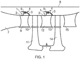
- FIG. 1 shows, in highly simplified representation, a side view of a partial area of an aircraft gas turbine.
- a combustion chamber is here indicated by the reference numeral 7.
- a downstream turbine features a turbine casing 8 within which stator vanes 9 of a first stage and rotor blades 10 of the first stage are shown.
- the rotor blades 10 are attached to a rotor disk 11 of the first stage in conventional manner.
- a stator vane 12 of a second stage is shown which is associated with a rotor blade 13 of the second stage, this rotor blade 13 again being attached to a rotor disk 14 of the second stage.
- Reference numeral 15 indicates a turbine exit guide vane.
- FIG. 1 further shows, in highly simplified form, a piston-cylinder unit 4 which is a part of an embodiment of the device for air mass flow control according to the present invention.
- the piston-cylinder unit 4 is located in the area of an inlet duct 1, exposed to a cooling air flow, with flow in the inlet duct issuing into an air duct 2 branching off from the inlet duct 1.
- the inlet duct 1 and air duct 2 may, for example, be used for ducting air from the cooling air flow to cool the stator vanes 9 or 12, respectively.
- a counter-pressure duct 3 is provided by which pressure, for instance, from the turbine section of the engine, is applied to the rearward area of the piston 5 of the piston-cylinder unit 4.
- the piston-cylinder unit 4 comprises a spring 16 by which a suitable pre-load is applied to the piston 5 to bias the piston in the desired direction.
- the pressure force in the inlet duct 1 exceeds the sum of the pressure force in the counter-pressure duct and of the pre-load force of the spring 16.
- the piston 5 is accordingly displaced such that the flow area of the air duct 2 is cleared.
- the pressure force in the counter-pressure duct 3 together with the pre-load force applied by the spring 16, exceeds the pressure force in the inlet duct 1, with the effect that the piston 5 is displaced to partly cover the free cross-section of the air duct 2, thus reducing the supply of air.
- the present invention seeks further to make efficient use of air flows for the purposes of cooling vanes.
- a vane cooling system for a gas turbine engine, the system comprising; a vane arranged on a stator and having a chamber extending continuously from a radially inner end to a radially outer end of the vane, the vane having a first inlet and a second inlet; a first cooling fluid feed in communication with the first inlet, a second cooling fluid feed in communication with the second inlet, the first cooling fluid feed having a higher pressure and temperature than the second cooling fluid feed, a flow adjustment device arranged for adjusting a flow of the second cooling fluid feed into the second inlet, wherein the chamber is divided by a restrictor plate to provide an inner chamber and a wall-side chamber bordering the inner chamber, the first inlet enters the wall-side chamber and the second inlet enters the central chamber.
- the first inlet may be arranged at a radially inner end of the vane.
- the second inlet may be arranged at a radially outer end of the vane.
- the vane is cooled by cooling fluid from the first cooling fluid feed.
- the pressure and temperature of this feed may be optimized for a known low power operating condition of the engine. For example, this may be a cruising condition.
- the flow adjustment device may be closed. During operations which require higher power (and so increased cooling effort), the flow adjustment device may be adjusted to introduce a top-up of cooling fluid from the second cooling fluid feed.
- the vane may be provided with multiple outlets for the cooling fluid.
- the outlets may be provided as an array of holes.
- the array of holes is arranged along or adjacent a trailing edge of the vane.
- the outlets may be configured to direct the spent cooling fluid into a working fluid passing through an annulus in which the vane sits.
- the vane may have an aerofoil shape in cross-section, the aerofoil shape defined by a pressure side wall and a suction side wall which meet one another at a leading edge and a trailing edge.
- the restrictor plate may extend from a trailing edge end of the pressure side wall spaced from but substantially in parallel alignment with the suction side wall, turn in parallel with the leading edge and continue to extend spaced from but substantially in parallel alignment with the pressure side wall to intercept itself, whereby to form an outer perimeter of the inner chamber and an inner perimeter of the wall-side chamber.
- the restrictor plate is configured to permit a restricted flow of air between the inner chamber and the wall-side chamber.
- the restrictor plate may be perforated with a number of through-holes. The total cross-section of the through-holes may be selected to restrict a flow of air passing between the chambers.
- the restrictor plate may comprise a different material than the pressure side wall and the suction side wall.
- the restrictor plate may be bonded to the pressure side wall using a cast bonding method.
- the first and second cooling fluid feeds may tap cooling air from the compressor of a gas turbine engine in which the vane cooling system is incorporated.
- the first and second cooling fluids may tap air from the same location on the compressor or different locations on the compressor.
- the first and/or second cooling fluid feeds tap off upstream of the outlet guide vane (OGV) of the compressor.
- OGV outlet guide vane
- One or both inlets may be obstructed by a flow restrictor, the flow restrictor configured to control the pressure of fluid passing into the chamber.
- the flow adjustment device may have a simple open-closed configuration.
- the flow adjustment device may be variable to provide a variable range of flow settings when open as well as an optional closed setting.
- the axially extending annular cavity may be defined by the radially outer casing and a segmented annular blade ring.
- the segmented annular blade ring sits radially adjacent tips of rotating blades of a rotor arranged axially adjacent the stator.
- Segments of the annular blade ring may be suspended from a radially inner surface of the radially outer casing, for example by means of segment hooks.
- the segments may define one or more radially inwardly directed gaps through which cooling fluid may pass from the axially extending annular cavity into an annulus in which the vane is located.
- the segments and adjacent radially outer casing may be configured to maintain a constant pressure in the axially extending annular cavity when cooling air enters the radially outer inlet. In an option, this may be achieved by dividing the annular space bounded by the casing and the segment into multiple cavities each in fluid communication. Entry and exit holes connecting the cavities may be proportioned to balance pressures within the axially extending annular cavity. Such an arrangement can discourage seal leakage to beneficially direct more cooling fluid to surfaces in need of cooling.
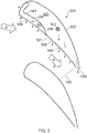
- Figure 2 shows a cross section of the vane which comprises part of a vane cooling system illustrated in Figure 4 and is described in more detail below.
- the hollow vane 20a is one of a circumferential array of vanes which include vane 20a and circumferentially adjacent vane 20b.
- the hollow vane 20a has a substantially aerofoil shaped cross section comprising a concave pressure side wall 21 and a convex suction side wall 22 which meet at a leading edge 23 and a trailing edge 24.
- a restrictor plate 25, 26 forms a loop within the aerofoil dividing a central cavity into an inner chamber 27 and a wall-side chamber 28.
- the pressure side 26 and suction side 25 of the restrictor plate are perforated with through-holes 29a, 29b.
- the through-holes 29a, 29b are arranged to serve as impingement cooling holes for cooling inwardly facing surfaces of the pressure side wall 21 and suction side wall 22.
- the wall-side chamber 28 is in fluid communication with one or more outlets 30 arranged along or adjacent the trailing edge 24.
- the pressure side wall 21 is provided with a number of outlets 31.
- the outlets 30, 31 are arranged generally to direct air to join a working fluid flow W which passes between the vanes 20a, 20b exiting through a throat 32.
- a separator 33 arranged adjacent the leading edge 23 separates two sides 28a, 28b of the wall-side chamber 28.
- Air flows through the chambers 27, 28 are represented by the arrows.
- the air flows shown are representative of flow during a cruise operation of a gas turbine engine of which the vane cooling system is a component.
- cooling air is provided from a single inlet (see Figure 4 ) through which the wall-side chamber 28 is fed on the pressure surface side 28a.
- FIG 3 shows the vane of Figure 2 during a higher power operation.
- the air flows shown are representative of flow during a MTO operation of a gas turbine engine of which the vane cooling system is a component.
- cooling air is fed via a first inlet into a wall-side chamber 28 on the pressure surface side 28a as described in relation to Figure 2 .
- a top-up flow is fed via a second inlet into the inner chamber 27.
- Spent cooling air exits the suction surface side of the wall-side chamber 28b through trailing edge outlets 30 and joins the work fluid flow W at or near the throat 32. Air also exits the pressure surface side of the wall-side chamber 28a through outlets 31 in the pressure side wall 21.
- the outlets 31 may be configured and arranged to provide a film cooling effect on the outwardly facing surface of the pressure side wall 21. It is to be noted that the outlets 31 are out of alignment with the through-holes 29a. This ensures a more even cooling along the pressure side wall 21.
- FIG 4 shows a side view of an embodiment of a vane cooling system in accordance with the invention, the vane cooling system incorporates vanes of the configuration already shown in Figures 2 and 3 and described above.
- the vane 20a spans an annulus 40 of a gas turbine engine the vane which has a radially inner inlet 41 which feeds the wall-side chamber 28 and a radially outer inlet 42 which feeds the inner chamber 27.
- a radially inner inlet 41 which feeds the wall-side chamber 28
- a radially outer inlet 42 which feeds the inner chamber 27.
- an array of outlets 30 opening through the vane 20a and directed in line with a flow of working fluid W flowing through the annulus 40.
- Axially upstream of the vane 20a (with respect to the direction of flow W of the working fluid), is a compressor (not shown).
- a first feed 43 is tapped from the compressor upstream. The feed 43 is arranged in fluid communication with the radially outer inlet 42.
- the feed 43 entering the radially outer inlet 42 may be controlled by means of a flow restrictor 44 obstructing a path of the feed 43 to the inlet 42.
- the feed 43 may be opened or closed or have its flow adjusted by means of valve 45.
- the inlet 42 passes through an annular casing 46 into the inner chamber 27 crossing an axially extending annular cavity 47. Downstream of the vane 20a, the axially extending annular cavity 47 is bounded on a radially inward side and an axially downstream side by a segmented ring 48. Segments of the segmented ring 48 are suspended from the casing 46 by means of suspension hooks 49.
- Rear inner 50 and rear outer 51 discharge flows are drawn into the annulus 40 to join the working fluid flow W.
- a flow may pass through a sloped bulk head 52 via one or more orifices 53.
- a second feed 54 supplies the radially inner inlet 41.
- the feed 54 is open during both high power and low power operations.
- the valve 45 to first feed 43 may be closed or positioned to allow a restricted fixed flow.
- the valve 45 is opened allowing the flow in the inner chamber 27 to be topped up with air from feed 43.
- the valve 45 may be adjustable to provide an optimum flow for the operating condition.
- An air transfer device 55 decouples the feed 43 from flow in the axially extending annular cavity 47. A constant pressure can thus be maintained in the cavity 47. A pressure differential downstream of the vane throat 32 draws a portion of air in the cavity 47 back into the working fluid flow W in the annulus 40 via a gap 56 between a chordal seal and the segmented ring 48, and a gap 57 between/through the seal segments.
- FIG. 5 shows an alternative embodiment during a higher power operation.
- the air flows shown are representative of flow during a MTO operation of a gas turbine engine of which the vane 520 cooling system is a component.
- cooling air 554 is fed via a first inlet into a wall-side chamber 528 on the pressure surface side wall 521.
- a top-up flow 543 (typically at lower pressure) is fed via a second inlet into the larger chamber 527.
- Air entering the larger chamber 527 is drawn spanwise through the vane 520 and exits through cooling holes 558 provided in the pressure surface side wall 521 where it joins a main work fluid flow W. A portion also exits through trailing edge outlet 530 and joins the work fluid flow W at or near the throat 532. Air 554 entering the wall side chamber 528 is drawn spanwise through the chamber 528 and exits through cooling holes 559 where it is swept up with the work fluid flow W.
- the outlets 558, 559 may be configured and arranged to provide a film cooling effect on the outwardly facing surface of the pressure side wall 521.
- FIG. 6 shows a third embodiment during a higher power operation.
- the air flows shown are representative of flow during a MTO operation of a gas turbine engine of which the vane 620 cooling system is a component.
- cooling air 654 is fed via a first inlet into a wall-side chamber 628 on the pressure surface side wall 621.
- a top-up flow 643 (typically at lower pressure) is fed via a second inlet into the larger chamber 627.
- Air entering the larger chamber 627 is drawn spanwise through the vane 620 and exits through cooling holes 659 provided in the pressure surface side wall 621 where it joins a main work fluid flow W on a pressure side of the vane 620 and may also pass through cooling holes 660 where it joins a main work fluid flow W on a suction surface side of the vane 620. A portion also exits through trailing edge outlet 630 and joins the work fluid flow W at or near the throat 632.
- Air 654 entering the wall side chamber 628 is drawn spanwise through the chamber 628 and exits through cooling holes 658 where it is swept up with the work fluid flow W on a pressure surface side 621 of the vane 620.
- the outlets 658, 659 and 660 may be configured and arranged to provide a film cooling effect on the outwardly facing surface of the pressure side wall 621 and the suction side wall 622.
- FIG 7 shows a side view of an embodiment of a vane cooling system in accordance with the invention, the vane cooling system incorporates vanes of the configuration already shown in Figures 5 and 6 and described above.
- the vane 720 spans an annulus 740 of a gas turbine engine.
- the vane has a central cavity which is divided by wall 727a to produce a first chamber 728 and a second chamber 727.
- the vane 720 has a radially inner inlet 741 which feeds the first chamber 728 and a radially outer inlet 742 which feeds the second chamber 727. Air exits the first chamber 728 through cooling holes 758.
- Along a trailing edge of the vane 720 is an array of outlets 730 opening through vane 720 and directed in line with a flow of working fluid W flowing through the annulus 740. Axially upstream of the vane (with respect to the direction of flow W of the working fluid), is a compressor (not shown).
- a first feed 743 is tapped from the compressor upstream.
- the feed is arranged in fluid communication with the radially outer inlet 742.
- the feed 743 entering the radially outer inlet 742 may be controlled by means of a flow restrictor 744 obstructing a path of the feed 743 to the inlet 742.
- the feed 743 may be opened or closed by means of valve 745.
- the inlet 742 passes through an annular casing 746 into the larger chamber 727 crossing an axially extending annular cavity 747. Downstream of the vane 720, the axially extending annular cavity 747 is bounded on a radially inward side and an axially downstream side by a segmented ring 748. Segments of the segmented ring 748 are suspended from the casing 746 by means of suspension hooks 749.
- Rear inner 750 and rear outer 751 discharge flows are drawn into the annulus 740 to join the working fluid flow W.
- a flow may pass through a sloped bulk head 752 via one or more orifices 753.
- a second feed 754 supplies the radially inner inlet 741.
- the feed is open during both high power and low power operations.
- the valve 745 to first feed 743 may be closed.
- the valve 745 is opened allowing the flow in the larger chamber 727 to receive air from feed 743.
- the valve 745 may be adjustable to provide an optimum flow for the operating condition.
- the air exits the larger chamber through outlets 730 in the trailing edge 724 as well as through film cooling holes provided in one or both of the pressure side and wall side of the vane (not shown).
- An air transfer device 755 decouples the feed 743 from flow in the axially extending annular cavity 747. A constant pressure can thus be maintained in the cavity 747. A pressure differential downstream of the vane throat 732 draws a portion of air in the cavity 747 back into the working fluid flow W in the annulus 740 via a gap 756 between a chordal seal and the segmented ring 748, and a gap 757 between/through the seal segments.
Landscapes
- Engineering & Computer Science (AREA)
- Mechanical Engineering (AREA)
- General Engineering & Computer Science (AREA)
- Chemical & Material Sciences (AREA)
- Combustion & Propulsion (AREA)
- Physics & Mathematics (AREA)
- Fluid Mechanics (AREA)
- Turbine Rotor Nozzle Sealing (AREA)
Abstract
Description
- The present invention is concerned with the cooling of vanes in a gas turbine engine. More particularly, the invention is concerned with cooling vanes by introducing cooling air into a cavity within the vane during operation of the gas turbine engine, where the cooling air is drawn from a supply present within the operating engine.
- Vanes are commonly arranged in a circumferential array spanning an annulus through which a working fluid is directed. A vane typically comprises an aerofoil with a pressure side wall and a suction side wall which meet one another at a leading edge and a trailing edge. The pressure and suction side walls border a central chamber into which cooling air may be delivered through a radially directed inlet. An array of outlets is commonly provided adjacent the trailing edge of the vane, typically on the pressure surface side. The outlets are directed to deliver spent cooling air into the main working fluid flow which is directed over the pressure side wall and suction side wall.
- The provision of air systems, in particular cooling-air systems for gas turbine engines, is known. Often, such systems when provided for cooling purposes in the hot section of the engine are dimensioned or designed such that they give adequate cooling under the most adverse conditions, for example at maximum power and the associated highest temperature ranges. Commonly, the source of cooling air is air taken off from the compressor.
- During different operating conditions, the temperature of the hot section varies and can often be below the highest experienced. Consequently, non-adaptive cooling systems can result in excessive air mass flow and overcooling under operating conditions requiring lesser cooling. A larger air mass than is needed is supplied to the turbine and subsequently exhausted. Where the cooling air is sourced from the compressor, the efficiency of the engine is compromised leading to increased specific fuel consumption and in the case of aircraft powered by such engines, the range of the aircraft may be reduced.
- Prior published US patent application no.
US6779967B2 seeks to address the described limitations by introducing adaptive valve control. An embodiment described inUS6779967B2 is reproduced inFigure 1 . -
FIG. 1 shows, in highly simplified representation, a side view of a partial area of an aircraft gas turbine. A combustion chamber is here indicated by thereference numeral 7. A downstream turbine features aturbine casing 8 within which stator vanes 9 of a first stage androtor blades 10 of the first stage are shown. Therotor blades 10 are attached to arotor disk 11 of the first stage in conventional manner. Further in the downstream direction, astator vane 12 of a second stage is shown which is associated with arotor blade 13 of the second stage, thisrotor blade 13 again being attached to arotor disk 14 of the second stage.Reference numeral 15 indicates a turbine exit guide vane. -
FIG. 1 further shows, in highly simplified form, a piston-cylinder unit 4 which is a part of an embodiment of the device for air mass flow control according to the present invention. The piston-cylinder unit 4 is located in the area of aninlet duct 1, exposed to a cooling air flow, with flow in the inlet duct issuing into anair duct 2 branching off from theinlet duct 1. Theinlet duct 1 andair duct 2 may, for example, be used for ducting air from the cooling air flow to cool thestator vanes - In the downstream direction, a counter-pressure duct 3 is provided by which pressure, for instance, from the turbine section of the engine, is applied to the rearward area of the
piston 5 of the piston-cylinder unit 4. Furthermore, the piston-cylinder unit 4 comprises a spring 16 by which a suitable pre-load is applied to thepiston 5 to bias the piston in the desired direction. - During operations with a high pressure difference, the pressure force in the
inlet duct 1 exceeds the sum of the pressure force in the counter-pressure duct and of the pre-load force of the spring 16. Thepiston 5 is accordingly displaced such that the flow area of theair duct 2 is cleared. During operations with a low pressure difference, the pressure force in the counter-pressure duct 3, together with the pre-load force applied by the spring 16, exceeds the pressure force in theinlet duct 1, with the effect that thepiston 5 is displaced to partly cover the free cross-section of theair duct 2, thus reducing the supply of air. - The present invention seeks further to make efficient use of air flows for the purposes of cooling vanes.
- In accordance with the invention there is provided a vane cooling system for a gas turbine engine, the system comprising;
a vane arranged on a stator and having a chamber extending continuously from a radially inner end to a radially outer end of the vane,
the vane having a first inlet and a second inlet;
a first cooling fluid feed in communication with the first inlet,
a second cooling fluid feed in communication with the second inlet,
the first cooling fluid feed having a higher pressure and temperature than the second cooling fluid feed,
a flow adjustment device arranged for adjusting a flow of the second cooling fluid feed into the second inlet,
wherein the chamber is divided by a restrictor plate to provide an inner chamber and a wall-side chamber bordering the inner chamber, the first inlet enters the wall-side chamber and the second inlet enters the central chamber. - For example, the first inlet may be arranged at a radially inner end of the vane. The second inlet may be arranged at a radially outer end of the vane.
- At lower power operation, the vane is cooled by cooling fluid from the first cooling fluid feed. The pressure and temperature of this feed may be optimized for a known low power operating condition of the engine. For example, this may be a cruising condition. When the engine is operating at this known condition, the flow adjustment device may be closed. During operations which require higher power (and so increased cooling effort), the flow adjustment device may be adjusted to introduce a top-up of cooling fluid from the second cooling fluid feed.
- The vane may be provided with multiple outlets for the cooling fluid. The outlets may be provided as an array of holes. For example, the array of holes is arranged along or adjacent a trailing edge of the vane. The outlets may be configured to direct the spent cooling fluid into a working fluid passing through an annulus in which the vane sits.
- The vane may have an aerofoil shape in cross-section, the aerofoil shape defined by a pressure side wall and a suction side wall which meet one another at a leading edge and a trailing edge. The restrictor plate may extend from a trailing edge end of the pressure side wall spaced from but substantially in parallel alignment with the suction side wall, turn in parallel with the leading edge and continue to extend spaced from but substantially in parallel alignment with the pressure side wall to intercept itself, whereby to form an outer perimeter of the inner chamber and an inner perimeter of the wall-side chamber.
- The restrictor plate is configured to permit a restricted flow of air between the inner chamber and the wall-side chamber. The restrictor plate may be perforated with a number of through-holes. The total cross-section of the through-holes may be selected to restrict a flow of air passing between the chambers.
- The restrictor plate may comprise a different material than the pressure side wall and the suction side wall. For example, the restrictor plate may be bonded to the pressure side wall using a cast bonding method.
- The first and second cooling fluid feeds may tap cooling air from the compressor of a gas turbine engine in which the vane cooling system is incorporated. The first and second cooling fluids may tap air from the same location on the compressor or different locations on the compressor. For example, the first and/or second cooling fluid feeds tap off upstream of the outlet guide vane (OGV) of the compressor.
- One or both inlets may be obstructed by a flow restrictor, the flow restrictor configured to control the pressure of fluid passing into the chamber.
- The flow adjustment device may have a simple open-closed configuration. Alternatively, the flow adjustment device may be variable to provide a variable range of flow settings when open as well as an optional closed setting.
- Between vanes, the axially extending annular cavity may be defined by the radially outer casing and a segmented annular blade ring. Within an engine, the segmented annular blade ring sits radially adjacent tips of rotating blades of a rotor arranged axially adjacent the stator. Segments of the annular blade ring may be suspended from a radially inner surface of the radially outer casing, for example by means of segment hooks. The segments may define one or more radially inwardly directed gaps through which cooling fluid may pass from the axially extending annular cavity into an annulus in which the vane is located.
- In some embodiments, the segments and adjacent radially outer casing may be configured to maintain a constant pressure in the axially extending annular cavity when cooling air enters the radially outer inlet. In an option, this may be achieved by dividing the annular space bounded by the casing and the segment into multiple cavities each in fluid communication. Entry and exit holes connecting the cavities may be proportioned to balance pressures within the axially extending annular cavity. Such an arrangement can discourage seal leakage to beneficially direct more cooling fluid to surfaces in need of cooling.
- Embodiments of the invention will now be described with reference to the accompanying Figures in which:
-
Figure 1 shows a vane cooling system for a gas turbine engine as is known from the prior art; -
Figure 2 shows a novel vane of an embodiment of a vane cooling system in accordance with the invention during a low power engine operation; -
Figure 3 shows the vane ofFigure 2 during a high power operation; -
Figure 4 shows a side view of the vane cooling system comprising the vane ofFigures 2 and3 . -
Figure 1 has been described in more detail above. -
Figure 2 shows a cross section of the vane which comprises part of a vane cooling system illustrated inFigure 4 and is described in more detail below. As can be seen, thehollow vane 20a is one of a circumferential array of vanes which includevane 20a and circumferentiallyadjacent vane 20b. For clarity and simplicity, detail is only shown for onevane 20a, though other vanes in the array may be similarly configured. Thehollow vane 20a has a substantially aerofoil shaped cross section comprising a concavepressure side wall 21 and a convexsuction side wall 22 which meet at aleading edge 23 and a trailingedge 24. Arestrictor plate inner chamber 27 and a wall-side chamber 28. Thepressure side 26 andsuction side 25 of the restrictor plate are perforated with through-holes holes pressure side wall 21 andsuction side wall 22. The wall-side chamber 28 is in fluid communication with one ormore outlets 30 arranged along or adjacent the trailingedge 24. Thepressure side wall 21 is provided with a number ofoutlets 31. Theoutlets vanes throat 32. Aseparator 33 arranged adjacent the leadingedge 23 separates twosides side chamber 28. - Air flows through the
chambers Figure 2 , the air flows shown are representative of flow during a cruise operation of a gas turbine engine of which the vane cooling system is a component. During the cruise operation, cooling air is provided from a single inlet (seeFigure 4 ) through which the wall-side chamber 28 is fed on thepressure surface side 28a. - In the absence of a feed to the
inner chamber 27, air entering the pressure surface side of the wall-side chamber 28a is drawn into theinner chamber 27 through through-holes 29a, and into the suction surface side of the wall-side chamber through through-holes 29b where it impinges on an inwardly facing surface ofsuction side wall 22 exits through trailingedge outlet 30 and joins the work fluid flow W at thethroat 32. Air also exits throughoutlets 31 which may be configured and arranged to provide a film cooling effect on the outwardly facing surface of thepressure side wall 21. -
Figure 3 shows the vane ofFigure 2 during a higher power operation. The air flows shown are representative of flow during a MTO operation of a gas turbine engine of which the vane cooling system is a component. During the MTO operation, cooling air is fed via a first inlet into a wall-side chamber 28 on thepressure surface side 28a as described in relation toFigure 2 . In addition, a top-up flow is fed via a second inlet into theinner chamber 27. - In the absence of a feed to the suction surface side of the wall-
side chamber 28b, air entering theinner chamber 27 is drawn into the suction surface side of the wall-side chamber 28b through through-holes 29b. On further introduction of the top up flow, the pressure in theinner chamber 27 exceeds that in the pressure surface side of the wall-side chamber 28a and a counter-flow enters the pressure surface side of the wall-side chamber 28a from theinner chamber 27 through through-holes 29a. This provides an impingement cooling effect on an inwardly facing surface of thepressure side wall 21. - Spent cooling air exits the suction surface side of the wall-
side chamber 28b through trailingedge outlets 30 and joins the work fluid flow W at or near thethroat 32. Air also exits the pressure surface side of the wall-side chamber 28a throughoutlets 31 in thepressure side wall 21. Theoutlets 31 may be configured and arranged to provide a film cooling effect on the outwardly facing surface of thepressure side wall 21. It is to be noted that theoutlets 31 are out of alignment with the through-holes 29a. This ensures a more even cooling along thepressure side wall 21. -
Figure 4 shows a side view of an embodiment of a vane cooling system in accordance with the invention, the vane cooling system incorporates vanes of the configuration already shown inFigures 2 and3 and described above. - As can be seen the
vane 20a spans anannulus 40 of a gas turbine engine the vane which has a radiallyinner inlet 41 which feeds the wall-side chamber 28 and a radiallyouter inlet 42 which feeds theinner chamber 27. Along a trailing edge of the vane is an array ofoutlets 30 opening through thevane 20a and directed in line with a flow of working fluid W flowing through theannulus 40. Axially upstream of thevane 20a (with respect to the direction of flow W of the working fluid), is a compressor (not shown). Afirst feed 43 is tapped from the compressor upstream. Thefeed 43 is arranged in fluid communication with the radiallyouter inlet 42. Thefeed 43 entering the radiallyouter inlet 42 may be controlled by means of aflow restrictor 44 obstructing a path of thefeed 43 to theinlet 42. Thefeed 43 may be opened or closed or have its flow adjusted by means ofvalve 45. Theinlet 42 passes through anannular casing 46 into theinner chamber 27 crossing an axially extendingannular cavity 47. Downstream of thevane 20a, the axially extendingannular cavity 47 is bounded on a radially inward side and an axially downstream side by a segmentedring 48. Segments of the segmentedring 48 are suspended from thecasing 46 by means of suspension hooks 49. - Rear inner 50 and rear outer 51 discharge flows are drawn into the
annulus 40 to join the working fluid flow W. A flow may pass through asloped bulk head 52 via one or more orifices 53. - A
second feed 54 supplies the radiallyinner inlet 41. Thefeed 54 is open during both high power and low power operations. During a cruising operation thevalve 45 tofirst feed 43 may be closed or positioned to allow a restricted fixed flow. During a higher power operation such as maximum take-off, thevalve 45 is opened allowing the flow in theinner chamber 27 to be topped up with air fromfeed 43. Thevalve 45 may be adjustable to provide an optimum flow for the operating condition. - An
air transfer device 55 decouples thefeed 43 from flow in the axially extendingannular cavity 47. A constant pressure can thus be maintained in thecavity 47. A pressure differential downstream of thevane throat 32 draws a portion of air in thecavity 47 back into the working fluid flow W in theannulus 40 via agap 56 between a chordal seal and the segmentedring 48, and agap 57 between/through the seal segments. -
Figure 5 shows an alternative embodiment during a higher power operation. The air flows shown are representative of flow during a MTO operation of a gas turbine engine of which thevane 520 cooling system is a component. During the MTO operation, coolingair 554 is fed via a first inlet into a wall-side chamber 528 on the pressuresurface side wall 521. In addition, a top-up flow 543 (typically at lower pressure) is fed via a second inlet into thelarger chamber 527. - Air entering the
larger chamber 527 is drawn spanwise through thevane 520 and exits throughcooling holes 558 provided in the pressuresurface side wall 521 where it joins a main work fluid flow W. A portion also exits through trailingedge outlet 530 and joins the work fluid flow W at or near thethroat 532.Air 554 entering thewall side chamber 528 is drawn spanwise through thechamber 528 and exits throughcooling holes 559 where it is swept up with the work fluid flow W. - The
outlets pressure side wall 521. -
Figure 6 shows a third embodiment during a higher power operation. The air flows shown are representative of flow during a MTO operation of a gas turbine engine of which thevane 620 cooling system is a component. During the MTO operation, coolingair 654 is fed via a first inlet into a wall-side chamber 628 on the pressuresurface side wall 621. In addition, a top-up flow 643 (typically at lower pressure) is fed via a second inlet into thelarger chamber 627. - Air entering the
larger chamber 627 is drawn spanwise through thevane 620 and exits throughcooling holes 659 provided in the pressuresurface side wall 621 where it joins a main work fluid flow W on a pressure side of thevane 620 and may also pass through coolingholes 660 where it joins a main work fluid flow W on a suction surface side of thevane 620. A portion also exits through trailingedge outlet 630 and joins the work fluid flow W at or near the throat 632.Air 654 entering thewall side chamber 628 is drawn spanwise through thechamber 628 and exits throughcooling holes 658 where it is swept up with the work fluid flow W on apressure surface side 621 of thevane 620. - The
outlets pressure side wall 621 and thesuction side wall 622. -
Figure 7 shows a side view of an embodiment of a vane cooling system in accordance with the invention, the vane cooling system incorporates vanes of the configuration already shown inFigures 5 and6 and described above. - As can be seen the
vane 720 spans anannulus 740 of a gas turbine engine. The vane has a central cavity which is divided by wall 727a to produce afirst chamber 728 and asecond chamber 727. Thevane 720 has a radiallyinner inlet 741 which feeds thefirst chamber 728 and a radiallyouter inlet 742 which feeds thesecond chamber 727. Air exits thefirst chamber 728 through cooling holes 758. Along a trailing edge of thevane 720 is an array ofoutlets 730 opening throughvane 720 and directed in line with a flow of working fluid W flowing through theannulus 740. Axially upstream of the vane (with respect to the direction of flow W of the working fluid), is a compressor (not shown). Afirst feed 743 is tapped from the compressor upstream. The feed is arranged in fluid communication with the radiallyouter inlet 742. Thefeed 743 entering the radiallyouter inlet 742 may be controlled by means of aflow restrictor 744 obstructing a path of thefeed 743 to theinlet 742. Thefeed 743 may be opened or closed by means ofvalve 745. Theinlet 742 passes through anannular casing 746 into thelarger chamber 727 crossing an axially extendingannular cavity 747. Downstream of thevane 720, the axially extendingannular cavity 747 is bounded on a radially inward side and an axially downstream side by asegmented ring 748. Segments of thesegmented ring 748 are suspended from thecasing 746 by means of suspension hooks 749. - Rear inner 750 and rear outer 751 discharge flows are drawn into the
annulus 740 to join the working fluid flow W. A flow may pass through asloped bulk head 752 via one or more orifices 753. - A
second feed 754 supplies the radiallyinner inlet 741. The feed is open during both high power and low power operations. During a cruising operation thevalve 745 tofirst feed 743 may be closed. During a higher power operation such as maximum take-off, thevalve 745 is opened allowing the flow in thelarger chamber 727 to receive air fromfeed 743. Thevalve 745 may be adjustable to provide an optimum flow for the operating condition. The air exits the larger chamber throughoutlets 730 in the trailingedge 724 as well as through film cooling holes provided in one or both of the pressure side and wall side of the vane (not shown). - An
air transfer device 755 decouples thefeed 743 from flow in the axially extendingannular cavity 747. A constant pressure can thus be maintained in thecavity 747. A pressure differential downstream of thevane throat 732 draws a portion of air in thecavity 747 back into the working fluid flow W in theannulus 740 via agap 756 between a chordal seal and thesegmented ring 748, and agap 757 between/through the seal segments. - It will be understood that the invention is not limited to the embodiments above-described and various modifications and improvements can be made without departing from the invention as is defined by the appended claims. Except where mutually exclusive, any of the features may be employed separately or in combination with any other features and the disclosure extends to and includes all combinations and sub-combinations of one or more features described herein.
Claims (16)
- A vane cooling system for a gas turbine engine, the system comprising;
a vane (20a) arranged on a stator and having a chamber (27,28) extending continuously from a radially inner end to a radially outer end of the vane,
the vane (20a) having a first inlet (41) and a second inlet (42);
a first cooling fluid feed (54) in communication with the first inlet (41),
a second cooling fluid feed (43) in communication with the second inlet (42),
the first cooling fluid feed (54) having a higher pressure than the second cooling fluid feed (43),
a flow adjustment device (45) arranged for adjusting a flow of the second cooling fluid feed (43) into the second inlet (42),
wherein the chamber is divided by a plate (25,26) to provide a main chamber (27) and a wall-side chamber (28) bordering the inner chamber (27), the first inlet (41) enters the wall-side chamber (28) and the second inlet (42) enters the main chamber (27). - A vane cooling system as claimed in claim 1 wherein the first inlet (41) is arranged at a radially inner end of the vane (20a).
- A vane cooling system as claimed in claim 1 or claim 2 wherein the second inlet (42) is arranged at a radially outer end of the vane (20a).
- A vane cooling system as claimed in any preceding claim wherein the vane (20a) is provided with multiple outlets for the cooling fluid.
- A vane cooling system as claimed in claim 4 wherein outlets (30) are provided as an array of holes arranged along or adjacent a trailing edge (24) of the vane (20a).
- A vane cooling system as claimed in claim 4 or 5 wherein outlets (31) are provided as an array of holes in a pressure side wall (21) of the vane (20a).
- A vane cooling system as claimed in claim 4, 5 or 6 wherein the outlets (31, 32) are configured to direct the spent cooling fluid into a working fluid (W) passing through an annulus (40) in which the vane (20a) sits.
- A vane cooling system as claimed in any preceding claim wherein the vane has an aerofoil shape in cross-section, the aerofoil shape defined by a pressure side wall (21) and a suction side wall (22) which meet one another at a leading edge (23) and a trailing edge (24) and the restrictor plate (25,26) extends from a trailing edge (24) end of the pressure side wall (21) spaced from but substantially in parallel alignment with the suction side wall (22), turns in parallel with the leading edge (23) and continues to extend spaced from but substantially in parallel alignment with the pressure side wall (21) to intercept itself whereby to form an outer perimeter of the inner chamber (27) and an inner perimeter of the wall-side chamber (28).
- A vane cooling system as claimed in claim 8 wherein the plate (25,26) is perforated with a number of through holes (29a, 29b) and the total cross-section of the through holes (29a, 29b) is selected to restrict a flow of air passing between the chambers.
- A vane cooling system as claimed in any of claims 1 to 7 wherein the vane (520) has an aerofoil shape in cross-section, the aerofoil shape defined by a pressure side wall (521) and a suction side wall (522) which meet one another at a leading edge and a trailing edge and the plate (561) extends along a portion of the pressure side wall (521) to a position along the leading edge and wherein the pressure side wall (521) is perforated with a first array of outlet holes (558) exiting the main chamber (527) and a second array of outlet holes exiting the (559) exiting the wall side chamber (528).
- A vane cooling system as claimed in claim 10 wherein the suction side wall (622) is provided with an array of outlet holes (660) which are directed towards a throat between adjacent vanes (620).
- A vane cooling system as claimed in any preceding claim wherein the plate (25, 26; 561; 661) comprises a different material than that of the pressure side wall (21; 521; 621) and suction side wall (22; 522;622).
- A vane cooling system as claimed in any preceding claim wherein the plate (25, 26; 561; 661) is bonded to a wall (21, 22; 521, 522; 621, 622) of the vane (20a; 520; 620) using a cast bonding method.
- A gas turbine engine incorporating a turbine section, the turbine section incorporating a vane cooling system, the vane cooling system having a configuration substantially as described in any of claims 1 to 13.
- A gas turbine engine as claimed in claim 14 comprising a compressor upstream of the vane cooling system and wherein the first and second cooling fluid feeds (54, 43) tap air from the compressor.
- A gas turbine engine as claimed in claim 15 wherein the first cooling fluid feed (54) taps air from a different section of the compressor to that from which the second cooling fluid feed (43) taps air.
Applications Claiming Priority (1)
| Application Number | Priority Date | Filing Date | Title |
|---|---|---|---|
| GBGB1705553.4A GB201705553D0 (en) | 2017-04-06 | 2017-04-06 | Vane cooling system |
Publications (2)
| Publication Number | Publication Date |
|---|---|
| EP3385504A1 true EP3385504A1 (en) | 2018-10-10 |
| EP3385504B1 EP3385504B1 (en) | 2024-05-01 |
Family
ID=58744657
Family Applications (1)
| Application Number | Title | Priority Date | Filing Date |
|---|---|---|---|
| EP18160507.2A Active EP3385504B1 (en) | 2017-04-06 | 2018-03-07 | Vane cooling system |
Country Status (3)
| Country | Link |
|---|---|
| US (1) | US10648344B2 (en) |
| EP (1) | EP3385504B1 (en) |
| GB (1) | GB201705553D0 (en) |
Families Citing this family (3)
| Publication number | Priority date | Publication date | Assignee | Title |
|---|---|---|---|---|
| US11885240B2 (en) * | 2021-05-24 | 2024-01-30 | General Electric Company Polska sp.z o.o | Gas turbine engine with fluid circuit and ejector |
| CN116085067A (en) | 2021-11-05 | 2023-05-09 | 通用电气公司 | Gas turbine engine with fluid conduit system and method of operating the same |
| CN114183206B (en) * | 2021-12-29 | 2025-08-12 | 上海电气燃气轮机有限公司 | Structure and method for enhancing internal cooling of stationary blade |
Citations (5)
| Publication number | Priority date | Publication date | Assignee | Title |
|---|---|---|---|---|
| EP1221538A2 (en) * | 2001-01-05 | 2002-07-10 | General Electric Company | Cooled turbine stator blade |
| US6779967B2 (en) | 2001-12-12 | 2004-08-24 | Rolls-Royce Deutschland Ltd & Co Kg | Device for air mass flow control |
| EP1921292A2 (en) * | 2006-11-10 | 2008-05-14 | General Electric Company | Compound tubine cooled engine |
| US20090293495A1 (en) * | 2008-05-29 | 2009-12-03 | General Electric Company | Turbine airfoil with metered cooling cavity |
| EP2336524A2 (en) * | 2009-12-15 | 2011-06-22 | Kawasaki Jukogyo Kabushiki Kaisha | Gas turbine engine with cooling arrangement |
Family Cites Families (5)
| Publication number | Priority date | Publication date | Assignee | Title |
|---|---|---|---|---|
| US5498126A (en) | 1994-04-28 | 1996-03-12 | United Technologies Corporation | Airfoil with dual source cooling |
| US20140093392A1 (en) * | 2012-10-03 | 2014-04-03 | Rolls-Royce Plc | Gas turbine engine component |
| EP2938859B1 (en) * | 2012-12-29 | 2019-05-22 | United Technologies Corporation | Cooling architecture for turbine exhaust case |
| EP2990607A1 (en) * | 2014-08-28 | 2016-03-02 | Siemens Aktiengesellschaft | Cooling concept for turbine blades or vanes |
| US10450873B2 (en) * | 2017-07-31 | 2019-10-22 | Rolls-Royce Corporation | Airfoil edge cooling channels |
-
2017
- 2017-04-06 GB GBGB1705553.4A patent/GB201705553D0/en not_active Ceased
-
2018
- 2018-03-07 EP EP18160507.2A patent/EP3385504B1/en active Active
- 2018-04-05 US US15/945,755 patent/US10648344B2/en active Active
Patent Citations (5)
| Publication number | Priority date | Publication date | Assignee | Title |
|---|---|---|---|---|
| EP1221538A2 (en) * | 2001-01-05 | 2002-07-10 | General Electric Company | Cooled turbine stator blade |
| US6779967B2 (en) | 2001-12-12 | 2004-08-24 | Rolls-Royce Deutschland Ltd & Co Kg | Device for air mass flow control |
| EP1921292A2 (en) * | 2006-11-10 | 2008-05-14 | General Electric Company | Compound tubine cooled engine |
| US20090293495A1 (en) * | 2008-05-29 | 2009-12-03 | General Electric Company | Turbine airfoil with metered cooling cavity |
| EP2336524A2 (en) * | 2009-12-15 | 2011-06-22 | Kawasaki Jukogyo Kabushiki Kaisha | Gas turbine engine with cooling arrangement |
Also Published As
| Publication number | Publication date |
|---|---|
| EP3385504B1 (en) | 2024-05-01 |
| US10648344B2 (en) | 2020-05-12 |
| GB201705553D0 (en) | 2017-05-24 |
| US20180291747A1 (en) | 2018-10-11 |
Similar Documents
| Publication | Publication Date | Title |
|---|---|---|
| US10662809B2 (en) | Vane cooling system | |
| RU2387846C1 (en) | Method to cool by-pass gas turbine engine vanes and device to this end | |
| US4332133A (en) | Compressor bleed system for cooling and clearance control | |
| CN109083690B (en) | Turbine engine with variable effective throat | |
| CN107120146B (en) | Active HPC Gap Control | |
| JP2019074077A (en) | Method of clearance control for interdigitated turbine engine | |
| EP3153661A1 (en) | Method and system for modulated turbine cooling | |
| CN108868897B (en) | Inserts for turbine engine airfoils | |
| US10648344B2 (en) | Vane cooling system | |
| CN113123878B (en) | Variable area measurement with different α | |
| CA2927037C (en) | Rotor assembly with scoop | |
| US10502071B2 (en) | Controlling cooling flow in a cooled turbine vane or blade using an impingement tube | |
| CN109154197A (en) | Airfoil with skin cooling circuit | |
| US7140836B2 (en) | Casing arrangement | |
| EP3409901B1 (en) | Clearance control arrangement and corresponding gas turbine engine | |
| US20170328213A1 (en) | Engine component wall with a cooling circuit | |
| EP3721059B1 (en) | Heatshield for a gas turbine engine | |
| US10669879B2 (en) | Controlling tip clearance in a turbine | |
| CN113330190B (en) | System and method for providing compressed air to a gas turbine combustor | |
| EP3279433A1 (en) | Turbomachine component with flow guides for film cooling holes in film cooling arrangement |
Legal Events
| Date | Code | Title | Description |
|---|---|---|---|
| PUAI | Public reference made under article 153(3) epc to a published international application that has entered the european phase |
Free format text: ORIGINAL CODE: 0009012 |
|
| STAA | Information on the status of an ep patent application or granted ep patent |
Free format text: STATUS: THE APPLICATION HAS BEEN PUBLISHED |
|
| AK | Designated contracting states |
Kind code of ref document: A1 Designated state(s): AL AT BE BG CH CY CZ DE DK EE ES FI FR GB GR HR HU IE IS IT LI LT LU LV MC MK MT NL NO PL PT RO RS SE SI SK SM TR |
|
| AX | Request for extension of the european patent |
Extension state: BA ME |
|
| STAA | Information on the status of an ep patent application or granted ep patent |
Free format text: STATUS: REQUEST FOR EXAMINATION WAS MADE |
|
| 17P | Request for examination filed |
Effective date: 20190410 |
|
| RBV | Designated contracting states (corrected) |
Designated state(s): AL AT BE BG CH CY CZ DE DK EE ES FI FR GB GR HR HU IE IS IT LI LT LU LV MC MK MT NL NO PL PT RO RS SE SI SK SM TR |
|
| STAA | Information on the status of an ep patent application or granted ep patent |
Free format text: STATUS: EXAMINATION IS IN PROGRESS |
|
| 17Q | First examination report despatched |
Effective date: 20190912 |
|
| RAP1 | Party data changed (applicant data changed or rights of an application transferred) |
Owner name: ROLLS-ROYCE PLC |
|
| REG | Reference to a national code |
Ref country code: DE Ref legal event code: R079 Free format text: PREVIOUS MAIN CLASS: F01D0009020000 Ipc: F01D0005180000 Ref country code: DE Ref legal event code: R079 Ref document number: 602018068783 Country of ref document: DE Free format text: PREVIOUS MAIN CLASS: F01D0009020000 Ipc: F01D0005180000 |
|
| RIC1 | Information provided on ipc code assigned before grant |
Ipc: F01D 25/12 20060101ALI20230712BHEP Ipc: F01D 9/06 20060101ALI20230712BHEP Ipc: F02C 7/18 20060101ALI20230712BHEP Ipc: F01D 11/24 20060101ALI20230712BHEP Ipc: F01D 11/10 20060101ALI20230712BHEP Ipc: F01D 5/18 20060101AFI20230712BHEP |
|
| GRAP | Despatch of communication of intention to grant a patent |
Free format text: ORIGINAL CODE: EPIDOSNIGR1 |
|
| STAA | Information on the status of an ep patent application or granted ep patent |
Free format text: STATUS: GRANT OF PATENT IS INTENDED |
|
| GRAJ | Information related to disapproval of communication of intention to grant by the applicant or resumption of examination proceedings by the epo deleted |
Free format text: ORIGINAL CODE: EPIDOSDIGR1 |
|
| GRAP | Despatch of communication of intention to grant a patent |
Free format text: ORIGINAL CODE: EPIDOSNIGR1 |
|
| GRAS | Grant fee paid |
Free format text: ORIGINAL CODE: EPIDOSNIGR3 |
|
| INTG | Intention to grant announced |
Effective date: 20230918 |
|
| INTG | Intention to grant announced |
Effective date: 20230928 |
|
| P01 | Opt-out of the competence of the unified patent court (upc) registered |
Effective date: 20231002 |
|
| GRAA | (expected) grant |
Free format text: ORIGINAL CODE: 0009210 |
|
| STAA | Information on the status of an ep patent application or granted ep patent |
Free format text: STATUS: THE PATENT HAS BEEN GRANTED |
|
| AK | Designated contracting states |
Kind code of ref document: B1 Designated state(s): AL AT BE BG CH CY CZ DE DK EE ES FI FR GB GR HR HU IE IS IT LI LT LU LV MC MK MT NL NO PL PT RO RS SE SI SK SM TR |
|
| REG | Reference to a national code |
Ref country code: GB Ref legal event code: FG4D |
|
| REG | Reference to a national code |
Ref country code: CH Ref legal event code: EP |
|
| REG | Reference to a national code |
Ref country code: DE Ref legal event code: R096 Ref document number: 602018068783 Country of ref document: DE |
|
| REG | Reference to a national code |
Ref country code: IE Ref legal event code: FG4D |
|
| REG | Reference to a national code |
Ref country code: LT Ref legal event code: MG9D |
|
| REG | Reference to a national code |
Ref country code: NL Ref legal event code: MP Effective date: 20240501 |
|
| PG25 | Lapsed in a contracting state [announced via postgrant information from national office to epo] |
Ref country code: IS Free format text: LAPSE BECAUSE OF FAILURE TO SUBMIT A TRANSLATION OF THE DESCRIPTION OR TO PAY THE FEE WITHIN THE PRESCRIBED TIME-LIMIT Effective date: 20240901 |
|
| PG25 | Lapsed in a contracting state [announced via postgrant information from national office to epo] |
Ref country code: BG Free format text: LAPSE BECAUSE OF FAILURE TO SUBMIT A TRANSLATION OF THE DESCRIPTION OR TO PAY THE FEE WITHIN THE PRESCRIBED TIME-LIMIT Effective date: 20240501 |
|
| PG25 | Lapsed in a contracting state [announced via postgrant information from national office to epo] |
Ref country code: FI Free format text: LAPSE BECAUSE OF FAILURE TO SUBMIT A TRANSLATION OF THE DESCRIPTION OR TO PAY THE FEE WITHIN THE PRESCRIBED TIME-LIMIT Effective date: 20240501 Ref country code: HR Free format text: LAPSE BECAUSE OF FAILURE TO SUBMIT A TRANSLATION OF THE DESCRIPTION OR TO PAY THE FEE WITHIN THE PRESCRIBED TIME-LIMIT Effective date: 20240501 |
|
| PG25 | Lapsed in a contracting state [announced via postgrant information from national office to epo] |
Ref country code: GR Free format text: LAPSE BECAUSE OF FAILURE TO SUBMIT A TRANSLATION OF THE DESCRIPTION OR TO PAY THE FEE WITHIN THE PRESCRIBED TIME-LIMIT Effective date: 20240802 |
|
| PG25 | Lapsed in a contracting state [announced via postgrant information from national office to epo] |
Ref country code: PT Free format text: LAPSE BECAUSE OF FAILURE TO SUBMIT A TRANSLATION OF THE DESCRIPTION OR TO PAY THE FEE WITHIN THE PRESCRIBED TIME-LIMIT Effective date: 20240902 |
|
| REG | Reference to a national code |
Ref country code: AT Ref legal event code: MK05 Ref document number: 1682584 Country of ref document: AT Kind code of ref document: T Effective date: 20240501 |
|
| PG25 | Lapsed in a contracting state [announced via postgrant information from national office to epo] |
Ref country code: NL Free format text: LAPSE BECAUSE OF FAILURE TO SUBMIT A TRANSLATION OF THE DESCRIPTION OR TO PAY THE FEE WITHIN THE PRESCRIBED TIME-LIMIT Effective date: 20240501 |
|
| PG25 | Lapsed in a contracting state [announced via postgrant information from national office to epo] |
Ref country code: ES Free format text: LAPSE BECAUSE OF FAILURE TO SUBMIT A TRANSLATION OF THE DESCRIPTION OR TO PAY THE FEE WITHIN THE PRESCRIBED TIME-LIMIT Effective date: 20240501 |
|
| PG25 | Lapsed in a contracting state [announced via postgrant information from national office to epo] |
Ref country code: AT Free format text: LAPSE BECAUSE OF FAILURE TO SUBMIT A TRANSLATION OF THE DESCRIPTION OR TO PAY THE FEE WITHIN THE PRESCRIBED TIME-LIMIT Effective date: 20240501 |
|
| PG25 | Lapsed in a contracting state [announced via postgrant information from national office to epo] |
Ref country code: PL Free format text: LAPSE BECAUSE OF FAILURE TO SUBMIT A TRANSLATION OF THE DESCRIPTION OR TO PAY THE FEE WITHIN THE PRESCRIBED TIME-LIMIT Effective date: 20240501 |
|
| PG25 | Lapsed in a contracting state [announced via postgrant information from national office to epo] |
Ref country code: LV Free format text: LAPSE BECAUSE OF FAILURE TO SUBMIT A TRANSLATION OF THE DESCRIPTION OR TO PAY THE FEE WITHIN THE PRESCRIBED TIME-LIMIT Effective date: 20240501 |
|
| PG25 | Lapsed in a contracting state [announced via postgrant information from national office to epo] |
Ref country code: PT Free format text: LAPSE BECAUSE OF FAILURE TO SUBMIT A TRANSLATION OF THE DESCRIPTION OR TO PAY THE FEE WITHIN THE PRESCRIBED TIME-LIMIT Effective date: 20240902 Ref country code: PL Free format text: LAPSE BECAUSE OF FAILURE TO SUBMIT A TRANSLATION OF THE DESCRIPTION OR TO PAY THE FEE WITHIN THE PRESCRIBED TIME-LIMIT Effective date: 20240501 Ref country code: NO Free format text: LAPSE BECAUSE OF FAILURE TO SUBMIT A TRANSLATION OF THE DESCRIPTION OR TO PAY THE FEE WITHIN THE PRESCRIBED TIME-LIMIT Effective date: 20240801 Ref country code: NL Free format text: LAPSE BECAUSE OF FAILURE TO SUBMIT A TRANSLATION OF THE DESCRIPTION OR TO PAY THE FEE WITHIN THE PRESCRIBED TIME-LIMIT Effective date: 20240501 Ref country code: LV Free format text: LAPSE BECAUSE OF FAILURE TO SUBMIT A TRANSLATION OF THE DESCRIPTION OR TO PAY THE FEE WITHIN THE PRESCRIBED TIME-LIMIT Effective date: 20240501 Ref country code: IS Free format text: LAPSE BECAUSE OF FAILURE TO SUBMIT A TRANSLATION OF THE DESCRIPTION OR TO PAY THE FEE WITHIN THE PRESCRIBED TIME-LIMIT Effective date: 20240901 Ref country code: HR Free format text: LAPSE BECAUSE OF FAILURE TO SUBMIT A TRANSLATION OF THE DESCRIPTION OR TO PAY THE FEE WITHIN THE PRESCRIBED TIME-LIMIT Effective date: 20240501 Ref country code: GR Free format text: LAPSE BECAUSE OF FAILURE TO SUBMIT A TRANSLATION OF THE DESCRIPTION OR TO PAY THE FEE WITHIN THE PRESCRIBED TIME-LIMIT Effective date: 20240802 Ref country code: FI Free format text: LAPSE BECAUSE OF FAILURE TO SUBMIT A TRANSLATION OF THE DESCRIPTION OR TO PAY THE FEE WITHIN THE PRESCRIBED TIME-LIMIT Effective date: 20240501 Ref country code: ES Free format text: LAPSE BECAUSE OF FAILURE TO SUBMIT A TRANSLATION OF THE DESCRIPTION OR TO PAY THE FEE WITHIN THE PRESCRIBED TIME-LIMIT Effective date: 20240501 Ref country code: BG Free format text: LAPSE BECAUSE OF FAILURE TO SUBMIT A TRANSLATION OF THE DESCRIPTION OR TO PAY THE FEE WITHIN THE PRESCRIBED TIME-LIMIT Effective date: 20240501 Ref country code: AT Free format text: LAPSE BECAUSE OF FAILURE TO SUBMIT A TRANSLATION OF THE DESCRIPTION OR TO PAY THE FEE WITHIN THE PRESCRIBED TIME-LIMIT Effective date: 20240501 Ref country code: RS Free format text: LAPSE BECAUSE OF FAILURE TO SUBMIT A TRANSLATION OF THE DESCRIPTION OR TO PAY THE FEE WITHIN THE PRESCRIBED TIME-LIMIT Effective date: 20240801 |
|
| PG25 | Lapsed in a contracting state [announced via postgrant information from national office to epo] |
Ref country code: DK Free format text: LAPSE BECAUSE OF FAILURE TO SUBMIT A TRANSLATION OF THE DESCRIPTION OR TO PAY THE FEE WITHIN THE PRESCRIBED TIME-LIMIT Effective date: 20240501 |
|
| PG25 | Lapsed in a contracting state [announced via postgrant information from national office to epo] |
Ref country code: EE Free format text: LAPSE BECAUSE OF FAILURE TO SUBMIT A TRANSLATION OF THE DESCRIPTION OR TO PAY THE FEE WITHIN THE PRESCRIBED TIME-LIMIT Effective date: 20240501 |
|
| PG25 | Lapsed in a contracting state [announced via postgrant information from national office to epo] |
Ref country code: CZ Free format text: LAPSE BECAUSE OF FAILURE TO SUBMIT A TRANSLATION OF THE DESCRIPTION OR TO PAY THE FEE WITHIN THE PRESCRIBED TIME-LIMIT Effective date: 20240501 |
|
| PG25 | Lapsed in a contracting state [announced via postgrant information from national office to epo] |
Ref country code: RO Free format text: LAPSE BECAUSE OF FAILURE TO SUBMIT A TRANSLATION OF THE DESCRIPTION OR TO PAY THE FEE WITHIN THE PRESCRIBED TIME-LIMIT Effective date: 20240501 Ref country code: SK Free format text: LAPSE BECAUSE OF FAILURE TO SUBMIT A TRANSLATION OF THE DESCRIPTION OR TO PAY THE FEE WITHIN THE PRESCRIBED TIME-LIMIT Effective date: 20240501 |
|
| PG25 | Lapsed in a contracting state [announced via postgrant information from national office to epo] |
Ref country code: SM Free format text: LAPSE BECAUSE OF FAILURE TO SUBMIT A TRANSLATION OF THE DESCRIPTION OR TO PAY THE FEE WITHIN THE PRESCRIBED TIME-LIMIT Effective date: 20240501 |
|
| PG25 | Lapsed in a contracting state [announced via postgrant information from national office to epo] |
Ref country code: SM Free format text: LAPSE BECAUSE OF FAILURE TO SUBMIT A TRANSLATION OF THE DESCRIPTION OR TO PAY THE FEE WITHIN THE PRESCRIBED TIME-LIMIT Effective date: 20240501 Ref country code: SK Free format text: LAPSE BECAUSE OF FAILURE TO SUBMIT A TRANSLATION OF THE DESCRIPTION OR TO PAY THE FEE WITHIN THE PRESCRIBED TIME-LIMIT Effective date: 20240501 Ref country code: RO Free format text: LAPSE BECAUSE OF FAILURE TO SUBMIT A TRANSLATION OF THE DESCRIPTION OR TO PAY THE FEE WITHIN THE PRESCRIBED TIME-LIMIT Effective date: 20240501 Ref country code: EE Free format text: LAPSE BECAUSE OF FAILURE TO SUBMIT A TRANSLATION OF THE DESCRIPTION OR TO PAY THE FEE WITHIN THE PRESCRIBED TIME-LIMIT Effective date: 20240501 Ref country code: DK Free format text: LAPSE BECAUSE OF FAILURE TO SUBMIT A TRANSLATION OF THE DESCRIPTION OR TO PAY THE FEE WITHIN THE PRESCRIBED TIME-LIMIT Effective date: 20240501 Ref country code: CZ Free format text: LAPSE BECAUSE OF FAILURE TO SUBMIT A TRANSLATION OF THE DESCRIPTION OR TO PAY THE FEE WITHIN THE PRESCRIBED TIME-LIMIT Effective date: 20240501 |
|
| REG | Reference to a national code |
Ref country code: DE Ref legal event code: R097 Ref document number: 602018068783 Country of ref document: DE |
|
| PG25 | Lapsed in a contracting state [announced via postgrant information from national office to epo] |
Ref country code: IT Free format text: LAPSE BECAUSE OF FAILURE TO SUBMIT A TRANSLATION OF THE DESCRIPTION OR TO PAY THE FEE WITHIN THE PRESCRIBED TIME-LIMIT Effective date: 20240501 |
|
| PLBE | No opposition filed within time limit |
Free format text: ORIGINAL CODE: 0009261 |
|
| STAA | Information on the status of an ep patent application or granted ep patent |
Free format text: STATUS: NO OPPOSITION FILED WITHIN TIME LIMIT |
|
| 26N | No opposition filed |
Effective date: 20250204 |
|
| PG25 | Lapsed in a contracting state [announced via postgrant information from national office to epo] |
Ref country code: SI Free format text: LAPSE BECAUSE OF FAILURE TO SUBMIT A TRANSLATION OF THE DESCRIPTION OR TO PAY THE FEE WITHIN THE PRESCRIBED TIME-LIMIT Effective date: 20240501 |
|
| PG25 | Lapsed in a contracting state [announced via postgrant information from national office to epo] |
Ref country code: SE Free format text: LAPSE BECAUSE OF FAILURE TO SUBMIT A TRANSLATION OF THE DESCRIPTION OR TO PAY THE FEE WITHIN THE PRESCRIBED TIME-LIMIT Effective date: 20240501 |
|
| PG25 | Lapsed in a contracting state [announced via postgrant information from national office to epo] |
Ref country code: MC Free format text: LAPSE BECAUSE OF FAILURE TO SUBMIT A TRANSLATION OF THE DESCRIPTION OR TO PAY THE FEE WITHIN THE PRESCRIBED TIME-LIMIT Effective date: 20240501 |
|
| REG | Reference to a national code |
Ref country code: CH Ref legal event code: H13 Free format text: ST27 STATUS EVENT CODE: U-0-0-H10-H13 (AS PROVIDED BY THE NATIONAL OFFICE) Effective date: 20251023 |
|
| PG25 | Lapsed in a contracting state [announced via postgrant information from national office to epo] |
Ref country code: LU Free format text: LAPSE BECAUSE OF NON-PAYMENT OF DUE FEES Effective date: 20250307 |
|
| REG | Reference to a national code |
Ref country code: BE Ref legal event code: MM Effective date: 20250331 |
|
| PG25 | Lapsed in a contracting state [announced via postgrant information from national office to epo] |
Ref country code: BE Free format text: LAPSE BECAUSE OF NON-PAYMENT OF DUE FEES Effective date: 20250331 |
|
| PG25 | Lapsed in a contracting state [announced via postgrant information from national office to epo] |
Ref country code: CH Free format text: LAPSE BECAUSE OF NON-PAYMENT OF DUE FEES Effective date: 20250331 |
|
| PG25 | Lapsed in a contracting state [announced via postgrant information from national office to epo] |
Ref country code: IE Free format text: LAPSE BECAUSE OF NON-PAYMENT OF DUE FEES Effective date: 20250307 |
|
| PGFP | Annual fee paid to national office [announced via postgrant information from national office to epo] |
Ref country code: GB Payment date: 20260323 Year of fee payment: 9 |
|
| PGFP | Annual fee paid to national office [announced via postgrant information from national office to epo] |
Ref country code: DE Payment date: 20260320 Year of fee payment: 9 |
|
| PGFP | Annual fee paid to national office [announced via postgrant information from national office to epo] |
Ref country code: FR Payment date: 20260323 Year of fee payment: 9 |