EP3385236A1 - Glass plate with antireflection film - Google Patents
Glass plate with antireflection film Download PDFInfo
- Publication number
- EP3385236A1 EP3385236A1 EP16870662.0A EP16870662A EP3385236A1 EP 3385236 A1 EP3385236 A1 EP 3385236A1 EP 16870662 A EP16870662 A EP 16870662A EP 3385236 A1 EP3385236 A1 EP 3385236A1
- Authority
- EP
- European Patent Office
- Prior art keywords
- refractive index
- index layer
- transparent
- glass sheet
- antireflection film
- Prior art date
- Legal status (The legal status is an assumption and is not a legal conclusion. Google has not performed a legal analysis and makes no representation as to the accuracy of the status listed.)
- Granted
Links
Images


Classifications
-
- C—CHEMISTRY; METALLURGY
- C03—GLASS; MINERAL OR SLAG WOOL
- C03C—CHEMICAL COMPOSITION OF GLASSES, GLAZES OR VITREOUS ENAMELS; SURFACE TREATMENT OF GLASS; SURFACE TREATMENT OF FIBRES OR FILAMENTS MADE FROM GLASS, MINERALS OR SLAGS; JOINING GLASS TO GLASS OR OTHER MATERIALS
- C03C17/00—Surface treatment of glass, not in the form of fibres or filaments, by coating
- C03C17/34—Surface treatment of glass, not in the form of fibres or filaments, by coating with at least two coatings having different compositions
- C03C17/3411—Surface treatment of glass, not in the form of fibres or filaments, by coating with at least two coatings having different compositions with at least two coatings of inorganic materials
- C03C17/3417—Surface treatment of glass, not in the form of fibres or filaments, by coating with at least two coatings having different compositions with at least two coatings of inorganic materials all coatings being oxide coatings
-
- B—PERFORMING OPERATIONS; TRANSPORTING
- B32—LAYERED PRODUCTS
- B32B—LAYERED PRODUCTS, i.e. PRODUCTS BUILT-UP OF STRATA OF FLAT OR NON-FLAT, e.g. CELLULAR OR HONEYCOMB, FORM
- B32B7/00—Layered products characterised by the relation between layers; Layered products characterised by the relative orientation of features between layers, or by the relative values of a measurable parameter between layers, i.e. products comprising layers having different physical, chemical or physicochemical properties; Layered products characterised by the interconnection of layers
- B32B7/02—Physical, chemical or physicochemical properties
- B32B7/023—Optical properties
-
- G—PHYSICS
- G02—OPTICS
- G02B—OPTICAL ELEMENTS, SYSTEMS OR APPARATUS
- G02B1/00—Optical elements characterised by the material of which they are made; Optical coatings for optical elements
- G02B1/10—Optical coatings produced by application to, or surface treatment of, optical elements
- G02B1/11—Anti-reflection coatings
- G02B1/113—Anti-reflection coatings using inorganic layer materials only
- G02B1/115—Multilayers
-
- B—PERFORMING OPERATIONS; TRANSPORTING
- B32—LAYERED PRODUCTS
- B32B—LAYERED PRODUCTS, i.e. PRODUCTS BUILT-UP OF STRATA OF FLAT OR NON-FLAT, e.g. CELLULAR OR HONEYCOMB, FORM
- B32B17/00—Layered products essentially comprising sheet glass, or glass, slag, or like fibres
- B32B17/06—Layered products essentially comprising sheet glass, or glass, slag, or like fibres comprising glass as the main or only constituent of a layer, next to another layer of a specific material
- B32B17/10—Layered products essentially comprising sheet glass, or glass, slag, or like fibres comprising glass as the main or only constituent of a layer, next to another layer of a specific material of synthetic resin
- B32B17/10005—Layered products essentially comprising sheet glass, or glass, slag, or like fibres comprising glass as the main or only constituent of a layer, next to another layer of a specific material of synthetic resin laminated safety glass or glazing
- B32B17/10009—Layered products essentially comprising sheet glass, or glass, slag, or like fibres comprising glass as the main or only constituent of a layer, next to another layer of a specific material of synthetic resin laminated safety glass or glazing characterized by the number, the constitution or treatment of glass sheets
- B32B17/10036—Layered products essentially comprising sheet glass, or glass, slag, or like fibres comprising glass as the main or only constituent of a layer, next to another layer of a specific material of synthetic resin laminated safety glass or glazing characterized by the number, the constitution or treatment of glass sheets comprising two outer glass sheets
-
- B—PERFORMING OPERATIONS; TRANSPORTING
- B32—LAYERED PRODUCTS
- B32B—LAYERED PRODUCTS, i.e. PRODUCTS BUILT-UP OF STRATA OF FLAT OR NON-FLAT, e.g. CELLULAR OR HONEYCOMB, FORM
- B32B17/00—Layered products essentially comprising sheet glass, or glass, slag, or like fibres
- B32B17/06—Layered products essentially comprising sheet glass, or glass, slag, or like fibres comprising glass as the main or only constituent of a layer, next to another layer of a specific material
- B32B17/10—Layered products essentially comprising sheet glass, or glass, slag, or like fibres comprising glass as the main or only constituent of a layer, next to another layer of a specific material of synthetic resin
- B32B17/10005—Layered products essentially comprising sheet glass, or glass, slag, or like fibres comprising glass as the main or only constituent of a layer, next to another layer of a specific material of synthetic resin laminated safety glass or glazing
- B32B17/10165—Functional features of the laminated safety glass or glazing
- B32B17/10174—Coatings of a metallic or dielectric material on a constituent layer of glass or polymer
- B32B17/10201—Dielectric coatings
-
- B—PERFORMING OPERATIONS; TRANSPORTING
- B32—LAYERED PRODUCTS
- B32B—LAYERED PRODUCTS, i.e. PRODUCTS BUILT-UP OF STRATA OF FLAT OR NON-FLAT, e.g. CELLULAR OR HONEYCOMB, FORM
- B32B17/00—Layered products essentially comprising sheet glass, or glass, slag, or like fibres
- B32B17/06—Layered products essentially comprising sheet glass, or glass, slag, or like fibres comprising glass as the main or only constituent of a layer, next to another layer of a specific material
- B32B17/10—Layered products essentially comprising sheet glass, or glass, slag, or like fibres comprising glass as the main or only constituent of a layer, next to another layer of a specific material of synthetic resin
- B32B17/10005—Layered products essentially comprising sheet glass, or glass, slag, or like fibres comprising glass as the main or only constituent of a layer, next to another layer of a specific material of synthetic resin laminated safety glass or glazing
- B32B17/1055—Layered products essentially comprising sheet glass, or glass, slag, or like fibres comprising glass as the main or only constituent of a layer, next to another layer of a specific material of synthetic resin laminated safety glass or glazing characterized by the resin layer, i.e. interlayer
-
- C—CHEMISTRY; METALLURGY
- C03—GLASS; MINERAL OR SLAG WOOL
- C03C—CHEMICAL COMPOSITION OF GLASSES, GLAZES OR VITREOUS ENAMELS; SURFACE TREATMENT OF GLASS; SURFACE TREATMENT OF FIBRES OR FILAMENTS MADE FROM GLASS, MINERALS OR SLAGS; JOINING GLASS TO GLASS OR OTHER MATERIALS
- C03C2217/00—Coatings on glass
- C03C2217/70—Properties of coatings
- C03C2217/73—Anti-reflective coatings with specific characteristics
- C03C2217/734—Anti-reflective coatings with specific characteristics comprising an alternation of high and low refractive indexes
-
- C—CHEMISTRY; METALLURGY
- C03—GLASS; MINERAL OR SLAG WOOL
- C03C—CHEMICAL COMPOSITION OF GLASSES, GLAZES OR VITREOUS ENAMELS; SURFACE TREATMENT OF GLASS; SURFACE TREATMENT OF FIBRES OR FILAMENTS MADE FROM GLASS, MINERALS OR SLAGS; JOINING GLASS TO GLASS OR OTHER MATERIALS
- C03C2218/00—Methods for coating glass
- C03C2218/10—Deposition methods
- C03C2218/15—Deposition methods from the vapour phase
- C03C2218/154—Deposition methods from the vapour phase by sputtering
- C03C2218/155—Deposition methods from the vapour phase by sputtering by reactive sputtering
-
- C—CHEMISTRY; METALLURGY
- C03—GLASS; MINERAL OR SLAG WOOL
- C03C—CHEMICAL COMPOSITION OF GLASSES, GLAZES OR VITREOUS ENAMELS; SURFACE TREATMENT OF GLASS; SURFACE TREATMENT OF FIBRES OR FILAMENTS MADE FROM GLASS, MINERALS OR SLAGS; JOINING GLASS TO GLASS OR OTHER MATERIALS
- C03C2218/00—Methods for coating glass
- C03C2218/30—Aspects of methods for coating glass not covered above
- C03C2218/365—Coating different sides of a glass substrate
Definitions
- the present invention relates to a glass sheet with an antireflection film.
- the glass sheet with an antireflection film Since a glass sheet with an antireflection film has a high transmittance, the application thereof to various fields can be expected.
- the glass sheet with an antireflection film is configured by arranging a laminated film on at least one surface of a glass sheet. By properly selecting respective layers configuring the laminated film, a light reflection-reducing effect can be obtained, and thereby a glass sheet with an antireflection film having a high transmittance can be obtained.
- Patent Literature 1 WO2006/080502
- the ZrO 2 -doped SiO 2 layer having the average hydrogen concentration C av of less than 10 atom% can be, for example, formed by sufficiently lowering the hydrogen concentration in the atmosphere at the time of film formation by a sputtering method or the like.
- an SiO 2 film may be used without using a silicon oxide doped with a zirconium oxide. Even by this configuration, it is possible to realize an antireflection film having a good appearance performance even after a heating step, which is a purpose of the present invention. However, since a layer mainly composed of a silicon oxide has a property of poor resistance against alkali, a silicon oxide doped with a zirconium oxide is more preferably used in the case of the use under an environment where alkali resistance is required.
- a difference between the glass sheet with an antireflection film according to the fifth embodiment and the above-described glass sheets with an antireflection film according to the first to fourth embodiments is that an antireflection film is provided on both surfaces of the glass sheet 140.
- the glass sheet 140 the same one as in the above-described first embodiment can be used and hence the description thereof is omitted here. Since the same films as in the above-described first to fourth embodiments can be used as the first transparent high refractive index layer 20, the first transparent low refractive index layer 30, the second transparent high refractive index layer 40, and the second transparent low refractive index layer 50, which are provided on or above the both surfaces of the glass sheet 140, the same reference numerals and signs are used. In FIG. 5 , the same reference numerals and signs are conveniently used as in the films of the first embodiment but they are not limited thereto.
- a low visible light reflectance can be realized from either side.
- the glass sheet can be suitably used in use applications where a low visible light reflectance is required from either side, for example, the case of the use as a window glass of buildings and, since the appearance performance is good even when heated, it can be suitably used also in the case where strengthening and/or bend processing are required.
- the laminated film has the following layer configuration from the side close to the glass substrate:
- the first transparent high refractive index layer was formed by a sputtering method under an atmosphere of Ar+O 2 (oxygen: 40 volume%) by using a Ti target doped with 30 atom% of Zr as a target.
- the sputtering pressure was set to 0.37 Pa.
- the first transparent low refractive index layer was formed by a sputtering method under an atmosphere of Ar+O 2 (oxygen: 60 volume%) by using an Si target as a target.
- the sputtering pressure was set to 0.37 Pa.
- the second transparent high refractive index layer was formed by a sputtering method under an atmosphere of Ar+O 2 (oxygen: 40 volume%) by using a Ti target doped with 30 atom% of Zr as a target.
- the sputtering pressure was set to 0.37 Pa.
- the second transparent low refractive index layer was formed by a sputtering method under an atmosphere of Ar+O 2 (oxygen: 60 volume%) by using an Si target doped with 10 atom% of Zr as a target.
- the sputtering pressure was set to 0.37 Pa.
- An antireflection treatment (surface roughening treatment) was performed on the surface at the side of the glass sheet, on which the laminated film was not arranged.
- a glass sheet with an antireflection film was manufactured by the same method as in Example 1. However, in Example 2, the laminated film had the following layer configuration:
- a glass sheet with an antireflection film was manufactured by the same method as in Example 1. However, in Example 3, the laminated film had the following layer configuration:
- the first and second transparent high refractive index layers were formed by a sputtering method under an atmosphere of Ar+O 2 (oxygen: 40 volume%) by using a Ti target doped with 20 atom% Zr as a target.
- the sputtering pressure was set to 0.37 Pa.
- a glass sheet with an antireflection film was manufactured by the same method as in Example 1. However, in Example 5, the laminated film had the following layer configuration:
- a glass sheet with an antireflection film was manufactured by the same method as in Example 1. However, in Example 7, the laminated film had the following layer configuration:
- a laminated film having the same configuration as in Example 1 was formed on both main surfaces of the glass sheet by the same method as in Example 1, thereby manufacturing a glass sheet with an antireflection film.
- a laminated film having the same configuration as in Example 3 was formed on both main surfaces of the glass sheet by the same method as in Example 3, thereby manufacturing a glass sheet with an antireflection film.
- a laminated film having the same configuration as in Example 4 was formed on both main surfaces of the glass sheet by the same method as in Example 4, thereby manufacturing a glass sheet with an antireflection film.
- a laminated film having the same configuration as in Example 5 was formed on both main surfaces of the glass sheet by the same method as in Example 5, thereby manufacturing a glass sheet with an antireflection film.
- a laminated film having the same configuration as in Example 6 was formed on both main surfaces of the glass sheet by the same method as in Example 6, thereby manufacturing a glass sheet with an antireflection film.
- a laminated film having the same configuration as in Example 7 was formed on both main surfaces of the glass sheet by the same method as in Example 7, thereby manufacturing a glass sheet with an antireflection film.
- Table 1 summarizes the layer configurations of the glass sheets with an antireflection film of Examples 1 to 14.
- Table 1 First high refractive index layer First low refractive index layer Second high refractive index layer Second low refractive index layer Ex. 1 film material ZrO 2 -doped TiO 2 (35.3 mol%) SiO 2 ZrO 2 -doped TiO 2 (35.3 mol%) ZrO 2 -doped SiO 2 (10.0 mol%) thickness 11.8 nm 32.9 nm 104.8 nm 83 nm Ex.
- the color tone of a light transmitted through the glass sheet with an antireflection film can be evaluated by measuring a transmitted color of the glass sheet with an antireflection film by using a common spectrometric device. More specifically, the evaluation can be performed by calculating CIE 1976 L*: a*: b* color system on the basis of optical spectra measured by a measuring device having an integrating sphere detector. In the case where a laminated film was formed only on one main surface as in the glass sheets with an antireflection film of Examples 1 to 7, there was measured a transmitted light of a light that entered from the side on which the antireflection film was located.
- ⁇ E In order to calculate the color difference ⁇ E before and after firing, first, change amounts ⁇ L*, ⁇ a*, and ⁇ b* of L*, a*, and b* before and after firing are calculated. Subsequently, ⁇ E can be calculated by computing the square root of the sum of squared values of respective values of ⁇ L*, ⁇ a*, and ⁇ b*.
- Table 2 shows evaluation results of Examples 1 to 7 and Table 3 shows evaluation results of Examples 8 to 14.
Landscapes
- Chemical & Material Sciences (AREA)
- Physics & Mathematics (AREA)
- Chemical Kinetics & Catalysis (AREA)
- Life Sciences & Earth Sciences (AREA)
- General Chemical & Material Sciences (AREA)
- Geochemistry & Mineralogy (AREA)
- Materials Engineering (AREA)
- Organic Chemistry (AREA)
- Inorganic Chemistry (AREA)
- Engineering & Computer Science (AREA)
- General Physics & Mathematics (AREA)
- Optics & Photonics (AREA)
- Surface Treatment Of Glass (AREA)
- Surface Treatment Of Optical Elements (AREA)
- Laminated Bodies (AREA)
Abstract
Description
- The present invention relates to a glass sheet with an antireflection film.
- Since a glass sheet with an antireflection film has a high transmittance, the application thereof to various fields can be expected. The glass sheet with an antireflection film is configured by arranging a laminated film on at least one surface of a glass sheet. By properly selecting respective layers configuring the laminated film, a light reflection-reducing effect can be obtained, and thereby a glass sheet with an antireflection film having a high transmittance can be obtained.
- In such a glass sheet with an antireflection film, for example, in the case where heating is performed in a strengthening step or a later processing step of the glass sheet after film formation of the antireflection film, there arise problems of a change in color tint of the antireflection film, a decrease in transmittance, an increase in haze, and the like. Thus, there has been a problem that it is difficult to obtain a glass sheet with an antireflection film having a preferable appearance performance.
- For example, in Patent Literature 1, it is described to suppress crack occurrence at the time of heating by using a monolayer film of a titanium oxynitride layer, a laminated film containing a titanium oxynitride layer and a zirconium oxide layer, or a laminated film containing a titanium oxynitride layer and a zirconium oxide layer, as a high refractive index film on a glass sheet.
- However, for further use in various use applications in future, there has been desired a glass sheet with an antireflection film having a better appearance performance than before.
- Patent Literature 1:
WO2006/080502 - It is an object to provide a glass sheet with an antireflection film, which has a good appearance performance even when heating is performed in a state that the film is attached and is capable of suitably being used in various use applications.
- The glass sheet with an antireflection film according to one embodiment of the present invention contains a glass sheet, a first transparent high refractive index layer located on the glass sheet, a first transparent low refractive index layer located on the first transparent high refractive index layer, a second transparent high refractive index layer located on the first transparent low refractive index layer, and a second transparent low refractive index layer located on the second transparent high refractive index layer, has a haze after heating at 600°C to 700°C for 15 minutes being 0.4% or less, and has a visible light reflectance measured from the side of the second transparent low refractive index layer based on JIS R 3106 being 1.0% or less.
- There can be provided a glass sheet with an antireflection film, which has a good appearance performance even when heating is performed in a state that the film is attached and is capable of suitably being used in various use applications.
-
- [
FIG. 1 ] It is a cross-sectional view schematically illustrating a glass sheet with an antireflection film according to a first embodiment of the present invention. - [
FIG. 2 ] It is a cross-sectional view schematically illustrating a glass sheet with an antireflection film according to a second embodiment of the present invention. - [
FIG. 3 ] It is a cross-sectional view schematically illustrating a glass sheet with an antireflection film according to a third embodiment of the present invention. - [
FIG. 4 ] It is a cross-sectional view schematically illustrating a glass sheet with an antireflection film according to a fourth embodiment of the present invention. - [
FIG. 5 ] It is a cross-sectional view schematically illustrating a glass sheet with an antireflection film according to a fifth embodiment of the present invention. - [
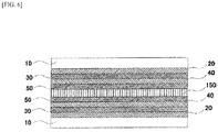
FIG. 6 ] It is a cross-sectional view schematically illustrating a glass laminate according to a sixth embodiment of the present invention. - The following will explain embodiments of the present invention in detail with reference to Drawings.
-
FIG. 1 is a cross-sectional view schematically illustrating a glass sheet with an antireflection film according to a first embodiment of the present invention. With reference toFIG. 1 , the glass sheet with an antireflection film according to the first embodiment of the present invention will be briefly described. - As illustrated in
FIG. 1 , the glass sheet with an antireflection film according to the first embodiment of the present invention is configured by aglass sheet 10, a first transparent highrefractive index layer 20, a first transparent lowrefractive index layer 30, a second transparent highrefractive index layer 40, and a second transparent lowrefractive index layer 50. Main layers to be provided on theglass sheet 10 are the above four layers but another layer may be provided in a range where it does not depart from the gist of the present invention. By alternately laminating the above-described transparent high refractive index layers and transparent low refractive index layers, an effect as an antireflection film can be obtained. - In the present Description, the term "transparent" means a state that the extinction coefficient at a wavelength of 400 nm is 0.01 or less. By using a film that is transparent, the visible light transmittance can be increased and also the color tone of a transmitted light can be kept good, so that the use is preferred. In the case where the extinction coefficient at a wavelength of 400 nm becomes more than 0.01, the visible light transmittance receives an influence that cannot be ignored and also there arises a problem that a transmitted light is tinted yellow.
- Also in the glass sheets with an antireflection film in the second to fourth embodiments to be described below in addition to the present embodiment, the haze after heating at 600°C to 700°C for 15 minutes is 0.4% or less and the visible light reflectance (Rv) measured from the side of the antireflection film is 1.0% or less based on JIS R 3106. Here, the term "heating at 600°C to 700°C for 15 minutes" means the case where heating is performed at any temperature ranging from 600°C to 700°C for 15 minutes. The temperature may be constant for 15 minutes, or the temperature may be changed in the range of 600°C to 700°C.
- As more preferable embodiment, the visible light reflectance (Rv) is 0.5% or less, the haze is 0.3% or less, and/or color change ΔE after heating at 600°C to 700°C for 15 minutes is 5 or less, more preferably 2 or less.
- The visible light reflectance can be measured by, for example, subjecting the surface of the glass sheet, on which the antireflection film is not located, to an antireflection treatment (surface-roughening treatment).
- The
glass sheet 10 is, for example, composed of an alkali-free glass, a soda-lime glass, an aluminosilicate glass, or the like, and may be strengthened. The strengthening method is not limited and may be a physical strengthening or a chemical strengthening. The thickness of theglass sheet 10 may be achieved by appropriate adjustment within about 0.2 to 5 mm. In the case of a glass sheet that is a soda-lime glass and is chemically strengthened, it contains, in terms of mass% based on oxides, 60 to 75% of SiO2, 2 to 12% of Al2O3, 2 to 11% of MgO, 0 to 10% of CaO, 0 to 3% of SrO, 0 to 3% of BaO, 10 to 18% of Na2O, 0 to 8% of K2O, and 0 to 4% of ZrO2 (total of the above components is 100% or less and usually 95% or more). In the case of a glass sheet that is an aluminosilicate glass and is chemically strengthened, it contains, in terms of mol% based on oxides, 61 to 70% of SiO2, 1 to 18% of Al2O3, 0 to 15% of MgO, 0 to 5% of CaO, 0 to 1% of SrO, 0 to 1% of BaO, 8 to 18% of Na2O, 0 to 6% of K2O, 0 to 4% of ZrO2, and 0 to 8% of B2O3. - The first transparent high
refractive index layer 20 is composed of a titanium oxide doped with a zirconium oxide, which is more specifically, for example, TiO2 doped with ZrO2. The doping amount of the zirconium oxide is 27 to 50 mol% and the refractive index of the first transparent highrefractive index layer 20 is 2.25 or more at a wavelength of 630 nm. The thickness of the first transparent highrefractive index layer 20 is preferably in the range of 5 nm to 40 nm. More preferably, the doping amount of the zirconium oxide is 30 to 40 mol%. By controlling the doping amount of the zirconium oxide to 30 to 40 mol%, it is possible to form a glass sheet with an antireflection film, which has further good appearance even when heated. - The first transparent low
refractive index layer 30 is mainly composed of a silicon oxide, which is more specifically SiO2. The first transparent lowrefractive index layer 30 has a refractive index that is smaller than those of the first transparent highrefractive index layer 20 and the second transparent highrefractive index layer 40 which are arranged above and below thelayer 30. The first transparent lowrefractive index layer 30 has, for example, a refractive index ranging from 1.4 to 1.8 at a wavelength of 630 nm. The thickness of the first transparent lowrefractive index layer 30 is preferably in the range of 5 nm to 50 nm. In the present application, the term "mainly composed of a material A" means that the objective layer contains the material A in an amount of at least 50 mol%. These layers can be formed using a sputtering method, a CVD (Chemical Vapor Deposition) method, a vapor deposition method, or the like. - The second transparent high
refractive index layer 40 is, for example, composed of a titanium oxide or a titanium oxide doped with a zirconium oxide, which is more specifically, for example, TiO2 doped with ZrO2. The second transparent highrefractive index layer 40 may not be doped with a zirconium oxide but one doped with a zirconium oxide is more preferable in view of appearance performance after heating. In the case of doping with a zirconium oxide, the doping amount of the zirconium oxide is 27 to 50 mol%, and the refractive index of the second transparent highrefractive index layer 40 is 2.25 or more at a wavelength of 630 nm. The thickness of the second transparent highrefractive index layer 40 is preferably in the range of 30 nm to 130 nm. As in the case of the first transparent highrefractive index layer 20, more preferably, the doping amount of the zirconium oxide is 30 to 40 mol%. In the case of doping with a zirconium oxide, it is preferable to use the second transparent highrefractive index layer 40 having a doping amount the same as that of the above-described first transparent highrefractive index layer 20, but one having a doping amount larger than that of the first transparent highrefractive index layer 20 may be used. By using the one having a doping amount larger than that of the first transparent highrefractive index layer 20, cracks owing to stress are hardly generated even at the time of bending the glass sheet with an antireflection film according to the first embodiment of the present invention by heating and thus, the glass plate can be suitably used as a bent glass, so that the use is preferred. - The second transparent low
refractive index layer 50 is, for example, composed of a silicon oxide or a silicon oxide doped with a zirconium oxide, which is more specifically, for example, SiO2 doped with ZrO2. The ZrO2-doped SiO2 layer shows good resistance against alkali. Therefore, in the glass sheet with an antireflection film according to the present embodiment, the ZrO2-doped SiO2 layer arranged as the second transparent lowrefractive index layer 50 exhibits a function as a protection film against alkali. Accordingly, even when the glass sheet with an antireflection film of the present embodiment comes into contact with water containing an alkali component, deterioration of the antireflection film can be significantly suppressed. - As the second transparent low
refractive index layer 50, an SiO2 film may be used without using a silicon oxide doped with a zirconium oxide. Even by this configuration, it is possible to realize an antireflection film having a good appearance performance even after a heating step, which is a purpose of the present invention. However, since a layer mainly composed of a silicon oxide has a property of poor resistance against alkali, a silicon oxide doped with a zirconium oxide is more preferably used in the case of the use under an environment where alkali resistance is required. - The doping amount of the zirconium oxide in the second transparent low
refractive index layer 50 is 5 to 50 mol%, more preferably 8 to 20 mol%. By doping the zirconium oxide in this range, the alkali resistance is improved. Furthermore, the second transparent lowrefractive index layer 50 more preferably has an average hydrogen concentration Cav of less than 10 atom%. By controlling the hydrogen concentration in this way, the protection function by the second transparent lowrefractive index layer 50 is further more improved. - Here, the average hydrogen concentration Cav of the second transparent low
refractive index layer 50 means a value measured by a high resolution ERDA (High Resolution Elastic Recoil Detection Analysis: HR-ERDA) method. The following will describe the details of the method of evaluating the average hydrogen concentration Cav by the HR-ERDA method. - For the measurement of the hydrogen concentration, a high resolution RBS analyzing device (HRBS500: manufactured by Kobe Steel, Ltd.) was used and analysis was performed by the HR-ERDA method.
- Set parameters at the measurement are as follows:
- Energy of incident ion: 480 keV
- Ion species: N+
- Set scattering angle: 30°
- Incident angle: 70° with respect to a normal line on a sample surface
- Current: about 2 nA
- Amount of irradiation: about 1.6 µC.
- Incidentally, for preventing static charge at the measurement, in each sample, before the measurement, about 5 nm of a carbon film was formed on the second transparent low
refractive index layer 50. - In order to avoid an influence from the carbon film, the hydrogen concentration was calculated as an average hydrogen concentration Cav by averaging values at a depth range of 15 nm to 20 nm in the measurement results (a graph showing a relation between the depth from the surface and the hydrogen intensity).
- The ZrO2-doped SiO2 layer having the average hydrogen concentration Cav of less than 10 atom% can be, for example, formed by sufficiently lowering the hydrogen concentration in the atmosphere at the time of film formation by a sputtering method or the like.
- Examples of methods for sufficiently lowering the hydrogen concentration in the atmosphere of film formation, include a method of baking the film formation chamber before film formation to sufficiently evacuate water and by-products such as hydrocarbon compounds absorbed on the wall surface of the film formation chamber, a method of arranging a cold trap that absorbs water and the by-products in the film formation chamber, a method of heating base materials beforehand to sufficiently degas water and by-products contained in the base materials, and the like.
- The second transparent low
refractive index layer 50 has a refractive index that is smaller than those of the first transparent highrefractive index layer 20 and the second transparent highrefractive index layer 40 which are provided below. The second transparent lowrefractive index layer 50 has, for example, a refractive index ranging from 1.4 to 1.8 at a wavelength of 630 nm. The thickness of the second transparent lowrefractive index layer 50 is preferably in the range of 65 nm to 120 nm. - In the present embodiment, as the first transparent high
refractive index layer 20, a titanium oxide doped with a zirconium oxide, specifically TiO2 doped with ZrO2 is used. Since a titanium oxide shrinks through proceeding of crystallization when a thermal treatment is performed and thus cracks and haze are generated to deteriorate the appearance, it is difficult to apply to a substrate which is to be subjected to a thermal treatment. On the other hand, in the case where a zirconium oxide is doped, it is possible to prevent the generation of cracks and haze even when a thermal treatment is performed after film formation. In the present embodiment, since the zirconium oxide is doped into the first transparent highrefractive index layer 20 that is close to theglass sheet 10, it is possible to form a glass sheet with an antireflection film, which has a further good appearance performance even after heating. In addition, in the case where the second transparent highrefractive index layer 40 is also doped with a zirconium oxide, it is possible to form a glass sheet with an antireflection film, which more stably has a good appearance performance. - In the present embodiment, the first transparent high
refractive index layer 20 is composed of a titanium oxide doped with a zirconium oxide and the first transparent lowrefractive index layer 30 is composed of a silicon oxide that is not doped with a zirconium oxide. By adopting this combination, the color change ΔE after heating can be easily suppressed as compared with the case where a silicon oxide doped with a zirconium oxide is used as the first transparent lowrefractive index layer 30, so that the embodiment is preferred. -
FIG. 2 is a cross-sectional view schematically illustrating a glass sheet with an antireflection film according to a second embodiment of the present invention. With reference toFIG. 2 , the glass sheet with an antireflection film according to the second embodiment of the present invention will be described. - As illustrated in
FIG. 2 , the glass sheet with an antireflection film according to the second embodiment is also configured by a first transparent highrefractive index layer 70, a first transparent lowrefractive index layer 30, a second transparent highrefractive index layer 80, and a second transparent lowrefractive index layer 50, which are located on or above aglass sheet 60, as in the above-described first embodiment. Here, since the same films as in the above-described first embodiment can be used as the first transparent low refractive index layer and the second transparent low refractive index layer, the same reference numerals and signs are used. As theglass sheet 60, the same one as in the above-described first embodiment can be used and hence the description thereof is omitted here. - The first transparent high
refractive index layer 70 is composed of a titanium oxide doped with a silicon oxide, which is more specifically, for example, TiO2 doped with SiO2. The doping amount of the silicon oxide is 12 to 30 mol% and the refractive index is 2.10 or more at a wavelength of 630 nm. The thickness of the first transparent highrefractive index layer 70 is preferably in the range of 5 nm to 40 nm. - The first transparent low
refractive index layer 30 is mainly composed of a silicon oxide, which is more specifically SiO2. The first transparent lowrefractive index layer 30 has a refractive index that is smaller than those of the first transparent highrefractive index layer 70 and the second transparent highrefractive index layer 80 which are arranged above and below. The first transparent lowrefractive index layer 30 has, for example, a refractive index ranging from 1.4 to 1.8 at a wavelength of 630 nm. The thickness of the first transparent lowrefractive index layer 30 is preferably in the range of 5 nm to 50 nm. - The second transparent high
refractive index layer 80 is, for example, composed of a titanium oxide or a titanium oxide doped with a silicon oxide, which is more specifically, for example, TiO2 doped with SiO2. The second transparent highrefractive index layer 80 may not be doped with a silicon oxide but one doped with a silicon oxide is more preferable in view of appearance performance after heating. In the case of doping with a silicon oxide, the doping amount of the silicon oxide is 12 to 30 mol%, and the refractive index of the second transparent highrefractive index layer 80 is 2.10 or more at a wavelength of 630 nm. The thickness of the second transparent highrefractive index layer 80 is preferably in the range of 30 nm to 130 nm. In the case of doping with a silicon oxide, it is preferable to use the second transparent highrefractive index layer 80 having a doping amount the same as that of the above-described first transparent highrefractive index layer 70, but one having a doping amount larger than that of the first transparent highrefractive index layer 70 may be used. By using the one having a doping amount larger than that of the first transparent highrefractive index layer 70, cracks owing to stress are hardly generated even at the time of bending the glass sheet with an antireflection film according to the second embodiment of the present invention by heating and thus, the glass plate can be suitably used as a bent glass, so that the use is preferred. - The second transparent low
refractive index layer 50 is, for example, composed of a silicon oxide or a silicon oxide doped with a zirconium oxide, and is more specifically composed of SiO2 doped with ZrO2. The ZrO2-doped SiO2 layer shows good resistance against alkali. Therefore, in the glass sheet with an antireflection film according to the present embodiment, the ZrO2-doped SiO2 layer arranged as the second transparent lowrefractive index layer 50 exhibits a function as a protection film against alkali. Accordingly, even when the glass sheet with an antireflection film of the present embodiment comes into contact with water containing an alkali component, deterioration of the antireflection film can be significantly suppressed. - As the second transparent low
refractive index layer 50, an SiO2 film may be used without using a silicon oxide doped with a zirconium oxide. Even by this configuration, it is possible to realize an antireflection film having a good appearance performance even after a heating step, which is a purpose of the present invention. However, since a layer mainly composed of a silicon oxide has a property of poor resistance against alkali, a silicon oxide doped with a zirconium oxide is more preferably used in the case of the use under an environment where alkali resistance is required. - The doping amount of the zirconium oxide in the second transparent low
refractive index layer 50 is 5 to 50 mol%, and more preferably 8 to 20 mol%. By doping the zirconium oxide in this range, the alkali resistance is improved. Furthermore, the second transparent lowrefractive index layer 50 more preferably has an average hydrogen concentration Cav of less than 10 atom%. By controlling the hydrogen concentration in this way, the protection function by the second transparent lowrefractive index layer 50 is further more improved. - The second transparent low
refractive index layer 50 has a refractive index that is smaller than those of the first transparent highrefractive index layer 70 and the second transparent highrefractive index layer 80 which are provided below. The second transparent lowrefractive index layer 50 has, for example, a refractive index ranging from 1.4 to 1.8 at a wavelength of 630 nm. The thickness of the second transparent lowrefractive index layer 50 is preferably in the range of 65 nm to 120 nm. - In the present embodiment, as the first transparent high
refractive index layer 70, a titanium oxide doped with a silicon oxide, specifically TiO2 doped with SiO2 is used. Since a titanium oxide shrinks through proceeding of crystallization when a thermal treatment is performed and thus cracks are generated to deteriorate the appearance, it is difficult to apply to a substrate which is to be subjected to a thermal treatment. On the other hand, in the case where a silicon oxide is doped, it is possible to prevent the generation of cracks even when a thermal treatment is performed after film formation. In the present embodiment, since the silicon oxide is doped into the first transparent highrefractive index layer 70 that is close to theglass sheet 10, it is possible to form a glass sheet with an antireflection film, which has a further good appearance performance even after heating. In addition, in the case where the second transparent highrefractive index layer 80 is also doped with a silicon oxide, it is possible to form a glass sheet with an antireflection film, which more stably has a good appearance performance. - In the present embodiment, the first transparent high
refractive index layer 70 is composed of a titanium oxide doped with a silicon oxide and the first transparent lowrefractive index layer 30 is composed of a silicon oxide that is not doped with a zirconium oxide. By adopting this combination, the color change ΔE after heating can be easily suppressed as compared with the case where a silicon oxide doped with a zirconium oxide is used as the first transparent lowrefractive index layer 30, so that the embodiment is preferred. -
FIG. 3 is a cross-sectional view schematically illustrating a glass sheet with an antireflection film according to a third embodiment of the present invention. With reference toFIG. 3 , the glass sheet with an antireflection film according to the third embodiment of the present invention will be described. - As illustrated in
FIG. 3 , the glass sheet with an antireflection film according to the second embodiment of the present invention is also configured by a first transparent highrefractive index layer 20, a first transparent lowrefractive index layer 110, a second transparent highrefractive index layer 40, and a second transparent lowrefractive index layer 50, which are located on or above aglass sheet 100, as in the above-described first embodiment. Here, since the same films as in the above-described first embodiment can be used as the first transparent high refractive index layer, the second transparent high refractive index layer and the second transparent low refractive index layer, the same reference numerals and signs are used. As theglass sheet 100, the same one as in the above-described first embodiment can be used and hence the description thereof is omitted here. - The first transparent high
refractive index layer 20 is composed of a titanium oxide doped with a zirconium oxide, which is more specifically, for example, TiO2 doped with ZrO2. The doping amount of the zirconium oxide is 27 to 50 mol% and the refractive index of the first transparent highrefractive index layer 20 is 2.25 or more at a wavelength of 630 nm. The thickness of the first transparent highrefractive index layer 20 is preferably in the range of 5 nm to 40 nm. More preferably, the doping amount of the zirconium oxide is 30 to 40 mol%. By controlling the doping amount of the zirconium oxide to 30 to 40 mol%, it is possible to form a glass sheet with an antireflection film, which has further good appearance even when heated. - The first transparent low
refractive index layer 110 is composed of a silicon oxide doped with a zirconium oxide, and is more specifically composed of SiO2 doped with ZrO2. The doping amount of the zirconium oxide in the first transparent lowrefractive index layer 110 is 5 to 50 mol%, and more preferably 8 to 20 mol%. By doping the zirconium oxide in this range, the alkali resistance is improved. - The second transparent high
refractive index layer 40 is, for example, composed of a titanium oxide or a titanium oxide doped with a zirconium oxide, which is more specifically, for example, TiO2 doped with ZrO2. The second transparent highrefractive index layer 40 may not be doped with a zirconium oxide but one doped with a zirconium oxide is more preferable in view of appearance performance after heating. In the case of doping with a zirconium oxide, the doping amount of the zirconium oxide is 27 to 50 mol%, and the refractive index of the second transparent highrefractive index layer 40 is 2.25 or more at a wavelength of 630 nm. The thickness of the second transparent highrefractive index layer 40 is preferably in the range of 30 nm to 130 nm. As in the case of the first transparent highrefractive index layer 20, more preferably, the doping amount of the zirconium oxide is 30 to 40 mol%. In the case of doping with a zirconium oxide, it is preferable to use the second transparent highrefractive index layer 40 having a doping amount the same as that of the above-described first transparent highrefractive index layer 20. but one having a doping amount larger than that of the first transparent highrefractive index layer 20 may be used. By using the one having a doping amount larger than that of the first transparent highrefractive index layer 20, cracks owing to stress are hardly generated even at the time of bending the glass sheet with an antireflection film according to the third embodiment of the present invention by heating and thus, the glass plate can be suitably used as a bent glass, so that the use is preferred. - The second transparent low
refractive index layer 50 is, for example, composed of a silicon oxide doped with a zirconium oxide, which is more specifically SiO2 doped with ZrO2. The ZrO2-doped SiO2 layer shows good resistance against alkali. Therefore, in the glass sheet with an antireflection film according to the present embodiment, the ZrO2-doped SiO2 layer arranged as the second transparent lowrefractive index layer 50 exhibits a function as a protection film against alkali. Accordingly, even when the glass sheet with an antireflection film of the present embodiment comes into contact with water containing an alkali component, deterioration of the antireflection film can be significantly suppressed. - The doping amount of the zirconium oxide in the second transparent low
refractive index layer 50 is 5 to 50 mol%, more preferably 8 to 20 mol%. By doping the zirconium oxide in this range, the alkali resistance is improved. Furthermore, the second transparent lowrefractive index layer 50 more preferably has an average hydrogen concentration Cav of less than 10 atom%. By controlling the hydrogen concentration in this way, the protection function by the second transparent lowrefractive index layer 50 is further more improved. - In the present embodiment, as the first transparent low
refractive index layer 110, a silicon oxide doped with a zirconium oxide is used as in the case of the second transparent lowrefractive index layer 50. By using the silicon oxide doped with a zirconium oxide as the first transparent lowrefractive index layer 110, chemical resistance can be improved as compared with the case where a silicon oxide that is not doped with a zirconium oxide is used as the first transparent lowrefractive index layer 110, so that the present embodiment is preferred. Since zirconium is doped into all the layers, use can be made in various environments. -
FIG. 4 is a cross-sectional view schematically illustrating a glass sheet with an antireflection film according to a fourth embodiment of the present invention. With reference toFIG. 4 , the glass sheet with an antireflection film according to the fourth embodiment of the present invention will be described. - As illustrated in
FIG. 4 , the glass sheet with an antireflection film according to the fourth embodiment of the present invention is also configured by a first transparent highrefractive index layer 70, a first transparent lowrefractive index layer 130, a second transparent highrefractive index layer 80, and a second transparent lowrefractive index layer 50, which are located on or above aglass sheet 120, as in the above-described second embodiment. Here, since the same films as in the above-described first embodiment can be used as the first transparent high refractive index layer, the second transparent high refractive index layer and the second transparent low refractive index layer, the same reference numerals and signs are used. As theglass sheet 120, the same one as in the above-described first embodiment can be used and hence the description thereof is omitted here. - The first transparent high
refractive index layer 70 is composed of a titanium oxide doped with a silicon oxide, which is more specifically, for example, TiO2 doped with SiO2. The doping amount of the silicon oxide is 12 to 30 mol% and the refractive index is 2.10 or more at a wavelength of 630 nm. The thickness of the first transparent highrefractive index layer 70 is preferably in the range of 5 nm to 40 nm. - The first transparent low
refractive index layer 130 is composed of a silicon oxide doped with a zirconium oxide, and is more specifically composed of SiO2 doped with ZrO2. The doping amount of the zirconium oxide in the first transparent lowrefractive index layer 130 is 5 to 50 mol%, and more preferably 8 to 20 mol%. By doping the zirconium oxide in this range, the alkali resistance is improved. - The second transparent high
refractive index layer 80 is, for example, composed of a titanium oxide or a titanium oxide doped with a silicon oxide, which is more specifically, for example, TiO2 doped with SiO2. The second transparent highrefractive index layer 80 may not be doped with a silicon oxide but one doped with a silicon oxide is more preferable in view of appearance performance after heating. In the case of doping with a silicon oxide, the doping amount of the silicon oxide is 12 to 30 mol%, and the refractive index of the second transparent highrefractive index layer 80 is 2.10 or more at a wavelength of 630 nm. The thickness of the second transparent highrefractive index layer 80 is preferably in the range of 30 nm to 130 nm. In the case of doping with a silicon oxide, it is preferable to use the second transparent highrefractive index layer 80 having a doping amount the same as that of the above-described first transparent highrefractive index layer 70, but one having a doping amount larger than that of the first transparent highrefractive index layer 70 may be used. By using the one having a doping amount larger than that of the first transparent highrefractive index layer 70, cracks owing to stress are hardly generated even at the time of bending the glass sheet with an antireflection film according to the fourth embodiment of the present invention by heating and thus, the glass plate can be suitably used as a bent glass, so that the use is preferred. - The second transparent low
refractive index layer 50 is composed of a silicon oxide doped with a zirconium oxide, and is more specifically composed of SiO2 doped with ZrO2. The ZrO2-doped SiO2 layer shows good resistance against alkali. Therefore, in the glass sheet with an antireflection film according to the present embodiment, the ZrO2-doped SiO2 layer arranged as the second transparent lowrefractive index layer 50 exhibits a function as a protection film against alkali. Accordingly, even when the glass sheet with an antireflection film of the present embodiment comes into contact with water containing an alkali component, deterioration of the antireflection film can be significantly suppressed. - The doping amount of the zirconium oxide in the second transparent low
refractive index layer 50 is 5 to 50 mol%, and more preferably 8 to 20 mol%. By doping the zirconium oxide in this range, the alkali resistance is improved. Furthermore, the second transparent lowrefractive index layer 50 more preferably has an average hydrogen concentration Cav of less than 10 atom%. By controlling the hydrogen concentration in this way, the protection function against water containing an alkali component by the second transparent lowrefractive index layer 50 is further more improved. - In the present embodiment, as the first transparent low
refractive index layer 130, a silicon oxide doped with a zirconium oxide, which is the same as in the case of the second transparent lowrefractive index layer 50, is used. By using the silicon oxide doped with a zirconium oxide as the first transparent lowrefractive index layer 130, chemical resistance can be improved as compared with the case where a silicon oxide that is not doped with a zirconium oxide is used as the first transparent lowrefractive index layer 130, so that the present embodiment is preferred. Since zirconium is doped into all the layers, use can be made in various environments. -
FIG. 5 is a cross-sectional view schematically illustrating a glass sheet with an antireflection film according to a fifth embodiment of the present invention. With reference toFIG. 5 , the glass sheet with an antireflection film according to the fifth embodiment of the present invention will be described. - As illustrated in
FIG. 5 , a difference between the glass sheet with an antireflection film according to the fifth embodiment and the above-described glass sheets with an antireflection film according to the first to fourth embodiments is that an antireflection film is provided on both surfaces of theglass sheet 140. As theglass sheet 140, the same one as in the above-described first embodiment can be used and hence the description thereof is omitted here. Since the same films as in the above-described first to fourth embodiments can be used as the first transparent highrefractive index layer 20, the first transparent lowrefractive index layer 30, the second transparent highrefractive index layer 40, and the second transparent lowrefractive index layer 50, which are provided on or above the both surfaces of theglass sheet 140, the same reference numerals and signs are used. InFIG. 5 , the same reference numerals and signs are conveniently used as in the films of the first embodiment but they are not limited thereto. - In the glass sheet with an antireflection film in the present embodiment, the haze after heating at 600°C to 700°C for 15 minutes is 0.4% or less and the visible light reflectance (Rv) measured based on JIS R 3106 is 2.0% or less from both sides. Here, the term "heating at 600°C to 700°C for 15 minutes" means a case where heating is performed at any temperature ranging from 600°C to 700°C for 15 minutes. The temperature may be constant for 15 minutes, or the temperature may be changed in the range of 600°C to 700°C.
- As more preferable embodiment, the visible light reflectance (Rv) is 1.01% or less, the haze is 0.3% or less, and/or color change ΔE after heating at 600°C to 700°C for 15 minutes is 5 or less, more preferably 2 or less.
- In the case where the antireflection film is located on both surfaces of the glass sheet as in the fifth embodiment, a low visible light reflectance can be realized from either side. For example, the glass sheet can be suitably used in use applications where a low visible light reflectance is required from either side, for example, the case of the use as a window glass of buildings and, since the appearance performance is good even when heated, it can be suitably used also in the case where strengthening and/or bend processing are required.
-
FIG. 6 is a cross-sectional view schematically illustrating a glass laminate according to a sixth embodiment of the present invention. With reference toFIG. 6 , the glass laminate according to the sixth embodiment of the present invention will be described. - As illustrated in
FIG. 6 , the sixth embodiment is a glass laminate in which the above-described glass sheets with an antireflection film according to the first to fourth embodiments are laminated with anintermediate film 150. InFIG. 6 , the glass sheet with an antireflection film according to the first embodiment is conveniently laminated, but it is not limited thereto. As theintermediate film 150, one used for conventional glass laminates can be used. - In the case where the glass laminate is used as in the present embodiment, since the antireflection film is not exposed outside, the film is difficult to deteriorate, so that the embodiment is preferred.
- The following will describe Examples of the present invention. In the following explanation, Examples 1 to 3 and Examples 8 to 10 are working examples and Examples 4 to 7 and Examples 11 to 14 are comparative examples.
- A laminated film was formed on one surface of a glass sheet by the following method to manufacture a glass sheet with an antireflection film.
- First, there was prepared a glass substrate (soda-lime glass) having a length of 50 mm, a width of 50 mm, and a thickness of 3 mm.
- Then, a laminated film was formed on one surface of the glass substrate by a sputtering method. The laminated film has the following layer configuration from the side close to the glass substrate:
- First transparent high refractive index layer: 35.3 mol% ZrO2-doped TiO2 layer
- First transparent low refractive index layer: SiO2 layer
- Second transparent high refractive index layer: 35.3 mol% ZrO2-doped TiO2 layer
- Second transparent low refractive index layer: 10.0 mol% ZrO2-doped SiO2 layer
- The first transparent high refractive index layer was formed by a sputtering method under an atmosphere of Ar+O2 (oxygen: 40 volume%) by using a Ti target doped with 30 atom% of Zr as a target. The sputtering pressure was set to 0.37 Pa.
- The first transparent low refractive index layer was formed by a sputtering method under an atmosphere of Ar+O2 (oxygen: 60 volume%) by using an Si target as a target. The sputtering pressure was set to 0.37 Pa.
- The second transparent high refractive index layer was formed by a sputtering method under an atmosphere of Ar+O2 (oxygen: 40 volume%) by using a Ti target doped with 30 atom% of Zr as a target. The sputtering pressure was set to 0.37 Pa.
- The second transparent low refractive index layer was formed by a sputtering method under an atmosphere of Ar+O2 (oxygen: 60 volume%) by using an Si target doped with 10 atom% of Zr as a target. The sputtering pressure was set to 0.37 Pa.
- An antireflection treatment (surface roughening treatment) was performed on the surface at the side of the glass sheet, on which the laminated film was not arranged.
- A glass sheet with an antireflection film was manufactured by the same method as in Example 1. However, in Example 2, the laminated film had the following layer configuration:
- First transparent high refractive index layer: 35.3 mol% ZrO2-doped TiO2 layer
- First transparent low refractive index layer: 10.0 mol% ZrO2-doped SiO2 layer
- Second transparent high refractive index layer: 35.3 mol% ZrO2-doped TiO2 layer
- Second transparent low refractive index layer: 10.0 mol% ZrO2-doped SiO2 layer
- A glass sheet with an antireflection film was manufactured by the same method as in Example 1. However, in Example 3, the laminated film had the following layer configuration:
- First transparent high refractive index layer: 20.2 mol% SiO2-doped TiO2 layer
- First transparent low refractive index layer: SiO2 layer
- Second transparent high refractive index layer: 20.2 mol% SiO2-doped TiO2 layer
- Second transparent low refractive index layer: 10.0 mol% ZrO2-doped SiO2 layer
- The first and second transparent high refractive index layers were formed by a sputtering method under an atmosphere of Ar+O2 (oxygen: 12 volume%) by using a TiOx target (x<2) doped with 8 mass% of Si as a target. The sputtering pressure was set to 0.37 Pa.
- A glass sheet with an antireflection film was manufactured by the same method as in Example 1. However, in Example 4, the laminated film had the following layer configuration:
- First transparent high refractive index layer: 26.2 mol% ZrO2-doped TiO2 layer
- First transparent low refractive index layer: SiO2 layer
- Second transparent high refractive index layer: 26.2 mol% ZrO2-doped TiO2 layer
- Second transparent low refractive index layer: 10.0 mol% ZrO2-doped SiO2 layer
- The first and second transparent high refractive index layers were formed by a sputtering method under an atmosphere of Ar+O2 (oxygen: 40 volume%) by using a Ti target doped with 20 atom% Zr as a target. The sputtering pressure was set to 0.37 Pa.
- A glass sheet with an antireflection film was manufactured by the same method as in Example 1. However, in Example 5, the laminated film had the following layer configuration:
- First transparent high refractive index layer: 10.4 mol% SiO2-doped TiO2 layer
- First transparent low refractive index layer: SiO2 layer
- Second transparent high refractive index layer: 10.4 mol% SiO2-doped TiO2 layer
- Second transparent low refractive index layer: laminate structure of SiO2 layer and 10.0 mol% ZrO2-doped SiO2 layer
- The first and second transparent high refractive index layers were formed by a sputtering method under an atmosphere of Ar+O2 (oxygen: 12 volume%) by using a TiOx target (x<2) doped with 3 mass% of Si as a target. The sputtering pressure was set to 0.37 Pa.
- A glass sheet with an antireflection film was manufactured by the same method as in Example 1. However, in Example 6, the laminated film had the following layer configuration:
- First transparent high refractive index layer: TiO2 layer
- First transparent low refractive index layer: SiO2 layer
- Second transparent high refractive index layer: TiO2 layer
- Second transparent low refractive index layer: 10.0 mol% ZrO2-doped SiO2 layer
- The first and second transparent high refractive index layers were formed by a sputtering method under an atmosphere of Ar+O2 (oxygen: 8 volume%) by using a TiOx target (x<2) as a target. The sputtering pressure was set to 0.37 Pa.
- A glass sheet with an antireflection film was manufactured by the same method as in Example 1. However, in Example 7, the laminated film had the following layer configuration:
- First transparent high refractive index layer: TiO2 layer
- First transparent low refractive index layer: SiO2 layer
- Second transparent high refractive index layer: 35.3 mol% ZrO2-doped TiO2 layer
- Second transparent low refractive index layer: 10.0 mol% ZrO2-doped SiO2 layer
- A laminated film having the same configuration as in Example 1 was formed on both main surfaces of the glass sheet by the same method as in Example 1, thereby manufacturing a glass sheet with an antireflection film.
- A laminated film having the same configuration as in Example 2 was formed on both main surfaces of the glass sheet by the same method as in Example 2, thereby manufacturing a glass sheet with an antireflection film.
- A laminated film having the same configuration as in Example 3 was formed on both main surfaces of the glass sheet by the same method as in Example 3, thereby manufacturing a glass sheet with an antireflection film.
- A laminated film having the same configuration as in Example 4 was formed on both main surfaces of the glass sheet by the same method as in Example 4, thereby manufacturing a glass sheet with an antireflection film.
- A laminated film having the same configuration as in Example 5 was formed on both main surfaces of the glass sheet by the same method as in Example 5, thereby manufacturing a glass sheet with an antireflection film.
- A laminated film having the same configuration as in Example 6 was formed on both main surfaces of the glass sheet by the same method as in Example 6, thereby manufacturing a glass sheet with an antireflection film.
- A laminated film having the same configuration as in Example 7 was formed on both main surfaces of the glass sheet by the same method as in Example 7, thereby manufacturing a glass sheet with an antireflection film.
- In the manufacture of the glass sheets with an antireflection film of Examples 1 to 14, the same film formation apparatus was used and the film formation was started after the film formation apparatus was thoroughly evacuated.
- The following Table 1 summarizes the layer configurations of the glass sheets with an antireflection film of Examples 1 to 14.
-
Table 1 First high refractive index layer First low refractive index layer Second high refractive index layer Second low refractive index layer Ex. 1 film material ZrO2-doped TiO2 (35.3 mol%) SiO2 ZrO2-doped TiO2 (35.3 mol%) ZrO2-doped SiO2 (10.0 mol%) thickness 11.8 nm 32.9 nm 104.8 nm 83 nm Ex. 2 film material ZrO2-doped TiO2 (35.3 mol%) ZrO2-doped SiO2 (10.0 mol%) ZrO2-doped TiO2 (35.3 mol%) ZrO2-doped SiO2 (10.0 mol%) thickness 10.7 nm 36.4 nm 104 nm 83 nm Ex. 3 film material SiO2-doped TiO2 (20.2 mol%) SiO2 SiO2-doped TiO2 (20.2 mol%) ZrO2-doped SiO2 (10.0 mol%) thickness 13.8 nm 36.8 nm 122 nm 79.5 nm Ex. 4 film material ZrO2-doped TiO2 (26.2 mol%) SiO2 ZrO2-doped TiO2 (26.2 mol%) ZrO2-doped SiO2 (10.0 mol%) thickness 11.8 nm 35 nm 105 nm 84.3 nm Ex. 5 film material SiO2-doped TiO2 (10.4 mol%) SiO2 SiO2-doped TiO2 (10.4 mol%) SiO2/ZrO2-doped SiO2 (10.0 mol%) thickness 13.5 nm 35 nm 113.5 nm 35.3 nm/51 nm Ex. 6 film material TiO2 SiO2 TiO2 ZrO2-doped SiO2 (10.0 mol%) thickness 13.1 nm 35 nm 113.5 nm 85.3 nm Ex. 7 film material TiO2 SiO2 ZrO2-doped TiO2 (35.3 mol%) ZrO2-doped SiO2 (10.0 mol%) thickness 11 nm 33.5 nm 104.3 nm 83.3 nm - For the glass sheets with an antireflection film of Examples 1 to 14 and ones after firing them at 675°C for 15 minutes, the following evaluations were carried out.
- It can be said that the lower the visible light reflectance Rv of the glass sheet with an antireflection film is, the better the low reflection characteristic is.
- In the case where a laminated film was formed only on one main surface as in the glass sheets with an antireflection film of Examples 1 to 7, a light was applied from the side on which the antireflection film was located in a state that the other surface had been subjected to a surface roughening treatment, and the measurement was conducted based on JIS R 3106. In the case of Examples 8 to 14 where the antireflection film was located on both main surfaces of the glass sheet, the measurement was performed without further treatment.
- The color tone of a light transmitted through the glass sheet with an antireflection film can be evaluated by measuring a transmitted color of the glass sheet with an antireflection film by using a common spectrometric device. More specifically, the evaluation can be performed by calculating CIE 1976 L*: a*: b* color system on the basis of optical spectra measured by a measuring device having an integrating sphere detector. In the case where a laminated film was formed only on one main surface as in the glass sheets with an antireflection film of Examples 1 to 7, there was measured a transmitted light of a light that entered from the side on which the antireflection film was located.
- In order to calculate the color difference ΔE before and after firing, first, change amounts ΔL*, Δa*, and Δb* of L*, a*, and b* before and after firing are calculated. Subsequently, ΔE can be calculated by computing the square root of the sum of squared values of respective values of ΔL*, Δa*, and Δb*.
- In the case where a laminated film was formed only on one main surface as in the glass sheets with an antireflection film of Examples I to 7, the haze of a light that entered from the side on which the antireflection film was located, was measured by using a haze meter HZ-2 manufactured by Suga Test Instruments Co., Ltd.
- Table 2 shows evaluation results of Examples 1 to 7 and Table 3 shows evaluation results of Examples 8 to 14.
-
Table 2 L* a* b* ΔE Rv (%) Hz (%) Ex. 1 before heating 3.33 -1.54 -7.00 0.58 0.34 0.02 after heating 2.88 -1.89 -6.88 0.29 0.09 Ex. 2 before heating 3.34 -1.78 -7.94 1.74 0.34 0.05 after heating 2.76 -0.77 -9.24 0.27 0.10 Ex. 3 before heating 7.32 -3.59 -0.97 4.66 0.80 0.01 after heating 6.13 -7.89 -2.35 0.65 0.02 Ex. 4 before heating 2.69 -2.14 -6.57 5.53 0.27 0.01 after heating 2.21 -1.81 -1.07 0.24 1.5 Ex. 5 before heating 3.06 -2.36 -5.66 5.13 0.31 0.02 after heating 3.38 -4.76 -1.13 0.36 1.01 Ex. 6 before heating 3.06 -1.70 -6.52 6.78 0.32 0.01 after heating 3.54 -4.61 -0.41 0.38 0.47 Ex. 7 before heating 3.80 -3.05 -6.97 4.04 0.39 0.02 after heating 4.04 -5.64 -3.87 0.42 0.46 -
Table 3 L* a* b* ΔE Rv (%) Hz (%) Ex. 8 before heating 6.84 -3.17 -11.51 1.31 0.71 0.03 after heating 5.75 -3.85 -11.76 0.58 0.10 Ex. 9 before heating 6.83 -3.60 -12.69 3.29 0.69 0.05 after heating 5.59 -1.69 -15.06 0.55 0.07 Ex. 10 before heating 14.43 -4.81 -1.49 9.02 1.78 0.01 after heating 11.79 -13.18 -3.56 1.32 0.01 Ex. 11 before heating 6.03 -4.23 -11.53 10.38 0.60 0.01 after heating 3.61 -4.48 -1.43 0.38 1.56 Ex. 12 before heating 7.37 -4.68 -9.93 9.16 0.76 0.02 after heating 7.17 -9.56 -2.19 0.77 1.18 Ex. 13 before heating 5.98 -3.96 -10.80 11.52 0.61 0.05 after heating 7.29 -9.16 -0.61 0.79 0.46 Ex. 14 before heating 7.88 -6.10 -10.89 6.77 0.82 0.06 after heating 8.30 -11.30 -6.57 0.87 0.43 - As is apparent from Table 2, it becomes possible to suppress the visible light reflectance Rv and haze after the heating treatment (firing) by suitably selecting materials of the first transparent high refractive index layer and of the first transparent low refractive index layer as in the above-described embodiments. Furthermore, it was also found that ΔE can be also kept low.
- As shown in Table 3, it was found that also in the case where the antireflection film was provided on both main surfaces, the same tendency as in Table 2 was observed.
- While the present invention has been described in detail and with reference to specific embodiments thereof, it will be apparent to one skilled in the art that various changes and modifications can be made therein without departing from the spirit and scope thereof. The present application is based on Japanese Patent Application (No.
2015-236620) filed on December 3, 2015 -
- 10, 60, 100, 120, 140 Glass sheet
- 20, 70 First transparent high refractive index layer
- 30, 110 First transparent low refractive index layer
- 40, 80 Second transparent high refractive index layer
- 50, 130 Second transparent low refractive index layer
- 150 Intermediate film
Claims (13)
- A glass sheet with an antireflection film,
comprising:a glass sheet,a first transparent high refractive index layer located on the glass sheet,a first transparent low refractive index layer located on the first transparent high refractive index layer,a second transparent high refractive index layer located on the first transparent low refractive index layer, anda second transparent low refractive index layer located on the second transparent high refractive index layer,having a haze after heating at 600°C to 700°C for 15 minutes being 0.4% or less, and
having a visible light reflectance measured from a side of the second transparent low refractive index layer based on JIS R 3106 being 1.0% or less. - The glass sheet with an antireflection film, according to Claim 1,
wherein the first transparent high refractive index layer is composed of a titanium oxide doped with a zirconium oxide in a concentration of 27 to 50 mol%, and
the first and second transparent low refractive index layers are mainly composed of a silicon oxide. - The glass sheet with an antireflection film, according to Claim 2,
wherein the first transparent high refractive index layer is composed of the titanium oxide doped with the zirconium oxide in a concentration of 30 to 40 mol%. - The glass sheet with an antireflection film, according to Claim 1,
wherein the first transparent high refractive index layer is composed of a titanium oxide doped with a silicon oxide in a concentration of 12 to 30 mol%, and
the first and second transparent low refractive index layers are mainly composed of a silicon oxide. - The glass sheet with an antireflection film, according to any one of Claims 2 to 4,
wherein the second transparent high refractive index layer is formed of a film of the same material as that of the first transparent high refractive index layer. - The glass sheet with an antireflection film, according to any one of Claims 2 to 4,
wherein the second transparent high refractive index layer comprises the same element doped as in the first transparent high refractive index layer, and an amount of the element is larger than that in the first transparent high refractive index layer. - The glass sheet with an antireflection film, according to any one of Claims 1 to 6, having a color change ΔE between before and after heating at 600°C to 700°C for 15 minutes being 5 or less.
- The glass sheet with an antireflection film, according to Claim 7, having the color change ΔE between before and after heating at 600°C to 700°C for 15 minutes being 2 or less.
- The glass sheet with an antireflection film, according to any one of Claims 1 to 8,
wherein the second transparent low refractive index layer is composed of a silicon oxide doped with a zirconium oxide in an amount of 5 to 50 mol%. - The glass sheet with an antireflection film, according to Claim 9,
wherein the second transparent low refractive index layer is composed of a silicon oxide doped with a zirconium oxide and has an average hydrogen concentration Cav measured by the following method being less than 10 atom%:
the method of measuring the average hydrogen concentration Cav of the second transparent low refractive index layer comprises measuring a hydrogen concentration at a depth range of 15 nm to 20 nm by a high resolution ERDA method in a state where 5 nm of a carbon film is formed on the second transparent low refractive index layer, and averaging the obtained values to obtain the average hydrogen concentration Cav. - The glass sheet with an antireflection film, according to Claim 9 or 10,
wherein the first transparent low refractive index layer is free of a zirconium oxide doped. - The glass sheet with an antireflection film, according to Claim 9 or 10,
wherein the first transparent low refractive index layer is composed of a silicon oxide doped with a zirconium oxide in an amount of 5 to 50 mol%. - The glass sheet with an antireflection film, according to any one of Claims 1 to 12,
comprising the first transparent high refractive index layer, the first transparent low refractive index layer, the second transparent high refractive index layer, and the second transparent low refractive index layer provided on both surfaces of the glass sheet,
having a haze after heating at 600°C to 700°C for 15 minutes being 0.4% or less, and
having a visible light reflectance measured from a side of the second transparent low refractive index layer based on JIS R 3106 being 2.0% or less.
Priority Applications (1)
| Application Number | Priority Date | Filing Date | Title |
|---|---|---|---|
| PL16870662T PL3385236T3 (en) | 2015-12-03 | 2016-11-29 | Glass plate with antireflection film |
Applications Claiming Priority (2)
| Application Number | Priority Date | Filing Date | Title |
|---|---|---|---|
| JP2015236620A JP6657872B2 (en) | 2015-12-03 | 2015-12-03 | Glass plate with anti-reflective coating |
| PCT/JP2016/085428 WO2017094725A1 (en) | 2015-12-03 | 2016-11-29 | Glass plate with antireflection film |
Publications (3)
| Publication Number | Publication Date |
|---|---|
| EP3385236A1 true EP3385236A1 (en) | 2018-10-10 |
| EP3385236A4 EP3385236A4 (en) | 2019-08-21 |
| EP3385236B1 EP3385236B1 (en) | 2021-10-13 |
Family
ID=58796804
Family Applications (1)
| Application Number | Title | Priority Date | Filing Date |
|---|---|---|---|
| EP16870662.0A Active EP3385236B1 (en) | 2015-12-03 | 2016-11-29 | Glass plate with antireflection film |
Country Status (7)
| Country | Link |
|---|---|
| US (1) | US10654746B2 (en) |
| EP (1) | EP3385236B1 (en) |
| JP (1) | JP6657872B2 (en) |
| ES (1) | ES2896077T3 (en) |
| HU (1) | HUE056964T2 (en) |
| PL (1) | PL3385236T3 (en) |
| WO (1) | WO2017094725A1 (en) |
Cited By (2)
| Publication number | Priority date | Publication date | Assignee | Title |
|---|---|---|---|---|
| WO2022117846A1 (en) | 2020-12-04 | 2022-06-09 | Agc Glass Europe | Enhanced anti-reflective effect |
| WO2022229023A1 (en) * | 2021-04-28 | 2022-11-03 | Agc Glass Europe | Greenhouse glass for reduction of overheating during the hot seasons |
Families Citing this family (5)
| Publication number | Priority date | Publication date | Assignee | Title |
|---|---|---|---|---|
| US11112538B2 (en) * | 2017-02-02 | 2021-09-07 | Guardian Glass, LLC | Heat treatable coated article having coatings on opposite sides of glass substrate |
| CN110894138A (en) * | 2019-01-30 | 2020-03-20 | 中山大学 | Environment-friendly automobile glass |
| CN110937821A (en) * | 2019-12-30 | 2020-03-31 | 青岛锦绣前程节能玻璃有限公司 | Temperable sunlight-controlled coated glass and preparation method thereof |
| EP3926370A1 (en) * | 2020-06-19 | 2021-12-22 | Essilor International | Optical article having a multilayered antireflective coating including an encapsulated metal film |
| EP4743424A1 (en) * | 2023-07-13 | 2026-05-20 | Agc Glass Europe | CORROSION-RESISTANT COATED GLASS |
Family Cites Families (12)
| Publication number | Priority date | Publication date | Assignee | Title |
|---|---|---|---|---|
| JPS62124503A (en) * | 1985-11-25 | 1987-06-05 | Minolta Camera Co Ltd | Multi-layered antireflection film |
| US5318830A (en) * | 1991-05-29 | 1994-06-07 | Central Glass Company, Limited | Glass pane with reflectance reducing coating |
| JP3039721B2 (en) | 1992-03-24 | 2000-05-08 | キヤノン株式会社 | Vapor deposition material and method for producing optical thin film using the vapor deposition material |
| FR2841894B1 (en) * | 2002-07-03 | 2006-03-10 | Saint Gobain | TRANSPARENT SUBSTRATE HAVING ANTIREFLECTION COATING |
| CN101111783B (en) | 2005-01-31 | 2010-12-08 | 旭硝子株式会社 | Substrate with anti-reflection coating |
| ITRM20060181A1 (en) | 2006-03-31 | 2007-10-01 | Pilkington Italia Spa | GLAZED GLASS SHEET |
| US20130183489A1 (en) * | 2012-01-13 | 2013-07-18 | Melissa Danielle Cremer | Reflection-resistant glass articles and methods for making and using same |
| WO2013176132A1 (en) | 2012-05-24 | 2013-11-28 | 旭硝子株式会社 | Method for manufacturing glass substrate and glass substrate |
| GB2518899A (en) * | 2013-10-07 | 2015-04-08 | Pilkington Group Ltd | Heat treatable coated glass pane |
| CN105814003B (en) * | 2013-12-16 | 2018-11-30 | Agc株式会社 | Glass with anti-reflection film and manufacturing method thereof |
| JP2017105643A (en) | 2014-04-24 | 2017-06-15 | 旭硝子株式会社 | Coated glass substrate and method for producing coated glass substrate |
| PL3284730T3 (en) * | 2015-04-14 | 2022-10-03 | AGC Inc. | Glass with antireflection film |
-
2015
- 2015-12-03 JP JP2015236620A patent/JP6657872B2/en active Active
-
2016
- 2016-11-29 PL PL16870662T patent/PL3385236T3/en unknown
- 2016-11-29 HU HUE16870662A patent/HUE056964T2/en unknown
- 2016-11-29 EP EP16870662.0A patent/EP3385236B1/en active Active
- 2016-11-29 ES ES16870662T patent/ES2896077T3/en active Active
- 2016-11-29 WO PCT/JP2016/085428 patent/WO2017094725A1/en not_active Ceased
-
2018
- 2018-05-23 US US15/986,990 patent/US10654746B2/en active Active
Cited By (2)
| Publication number | Priority date | Publication date | Assignee | Title |
|---|---|---|---|---|
| WO2022117846A1 (en) | 2020-12-04 | 2022-06-09 | Agc Glass Europe | Enhanced anti-reflective effect |
| WO2022229023A1 (en) * | 2021-04-28 | 2022-11-03 | Agc Glass Europe | Greenhouse glass for reduction of overheating during the hot seasons |
Also Published As
| Publication number | Publication date |
|---|---|
| US20180265403A1 (en) | 2018-09-20 |
| HUE056964T2 (en) | 2022-04-28 |
| WO2017094725A1 (en) | 2017-06-08 |
| EP3385236A4 (en) | 2019-08-21 |
| JP6657872B2 (en) | 2020-03-04 |
| ES2896077T3 (en) | 2022-02-23 |
| EP3385236B1 (en) | 2021-10-13 |
| US10654746B2 (en) | 2020-05-19 |
| PL3385236T3 (en) | 2022-01-31 |
| JP2017100921A (en) | 2017-06-08 |
Similar Documents
| Publication | Publication Date | Title |
|---|---|---|
| EP3385236B1 (en) | Glass plate with antireflection film | |
| JP5603322B2 (en) | Film coated plate glass | |
| CN102482144B (en) | Material and the window glass comprising this material | |
| ES2642800T3 (en) | Low emissivity glazing | |
| JP6112122B2 (en) | Float glass for chemical strengthening | |
| US20070279750A1 (en) | Substrate with antireflection film | |
| EP2998112B1 (en) | Protective film, reflective member, and production method for protective film | |
| TR201908549T4 (en) | Material covered with low visible transmission low dispersion coating that can be used in an insulating glass window unit for a gray appearance. | |
| EP3085673B1 (en) | Glass with anti-reflection film and method for manufacturing same | |
| US20100255294A1 (en) | Heat reflecting glass and process for producing heat reflecting glass | |
| US20230024206A1 (en) | Coating with Solar Control Properties for a Glass Substrate | |
| KR102523455B1 (en) | Solar-control or low-emissivity glazing comprising an upper protective layer | |
| US11319245B2 (en) | Coated protective glazing | |
| CN105705474B (en) | Glazing comprising a substrate coated with a stack containing a silver-based functional layer and a thick TiOx lower barrier layer | |
| JP6853486B2 (en) | Solar shielding member | |
| DK2585411T3 (en) | Triple insulating glass | |
| RU2717490C2 (en) | Glass containing functional coating, including silver and indium | |
| US9416582B2 (en) | Insulating glazing | |
| EP3284730B1 (en) | Glass with antireflection film | |
| JP2019530591A (en) | Functional building materials for window doors including low radiation coating and low radiation coating | |
| CN107207331A (en) | Glass plate and compound glass with stacked film | |
| KR20160067169A (en) | Thermal control glazing | |
| JP2015113268A (en) | Float glass for chemical strengthening | |
| JPWO2019181421A1 (en) | Glass substrate with laminated film and window glass | |
| KR20180118945A (en) | Low-emissivity glass |
Legal Events
| Date | Code | Title | Description |
|---|---|---|---|
| STAA | Information on the status of an ep patent application or granted ep patent |
Free format text: STATUS: THE INTERNATIONAL PUBLICATION HAS BEEN MADE |
|
| PUAI | Public reference made under article 153(3) epc to a published international application that has entered the european phase |
Free format text: ORIGINAL CODE: 0009012 |
|
| STAA | Information on the status of an ep patent application or granted ep patent |
Free format text: STATUS: REQUEST FOR EXAMINATION WAS MADE |
|
| 17P | Request for examination filed |
Effective date: 20180530 |
|
| AK | Designated contracting states |
Kind code of ref document: A1 Designated state(s): AL AT BE BG CH CY CZ DE DK EE ES FI FR GB GR HR HU IE IS IT LI LT LU LV MC MK MT NL NO PL PT RO RS SE SI SK SM TR |
|
| AX | Request for extension of the european patent |
Extension state: BA ME |
|
| DAV | Request for validation of the european patent (deleted) | ||
| DAX | Request for extension of the european patent (deleted) | ||
| A4 | Supplementary search report drawn up and despatched |
Effective date: 20190723 |
|
| RIC1 | Information provided on ipc code assigned before grant |
Ipc: C03C 17/34 20060101AFI20190717BHEP Ipc: G02B 1/115 20150101ALI20190717BHEP |
|
| STAA | Information on the status of an ep patent application or granted ep patent |
Free format text: STATUS: EXAMINATION IS IN PROGRESS |
|
| 17Q | First examination report despatched |
Effective date: 20200814 |
|
| GRAP | Despatch of communication of intention to grant a patent |
Free format text: ORIGINAL CODE: EPIDOSNIGR1 |
|
| STAA | Information on the status of an ep patent application or granted ep patent |
Free format text: STATUS: GRANT OF PATENT IS INTENDED |
|
| INTG | Intention to grant announced |
Effective date: 20210506 |
|
| RIN1 | Information on inventor provided before grant (corrected) |
Inventor name: KAWAHARA, HIROTOMO Inventor name: SUZUKI, KENICHI Inventor name: AOMINE, NOBUTAKA |
|
| GRAS | Grant fee paid |
Free format text: ORIGINAL CODE: EPIDOSNIGR3 |
|
| GRAA | (expected) grant |
Free format text: ORIGINAL CODE: 0009210 |
|
| STAA | Information on the status of an ep patent application or granted ep patent |
Free format text: STATUS: THE PATENT HAS BEEN GRANTED |
|
| AK | Designated contracting states |
Kind code of ref document: B1 Designated state(s): AL AT BE BG CH CY CZ DE DK EE ES FI FR GB GR HR HU IE IS IT LI LT LU LV MC MK MT NL NO PL PT RO RS SE SI SK SM TR |
|
| REG | Reference to a national code |
Ref country code: GB Ref legal event code: FG4D |
|
| REG | Reference to a national code |
Ref country code: CH Ref legal event code: EP |
|
| REG | Reference to a national code |
Ref country code: DE Ref legal event code: R096 Ref document number: 602016064986 Country of ref document: DE |
|
| REG | Reference to a national code |
Ref country code: IE Ref legal event code: FG4D |
|
| REG | Reference to a national code |
Ref country code: AT Ref legal event code: REF Ref document number: 1438092 Country of ref document: AT Kind code of ref document: T Effective date: 20211115 |
|
| PGFP | Annual fee paid to national office [announced via postgrant information from national office to epo] |
Ref country code: ES Payment date: 20211201 Year of fee payment: 6 |
|
| REG | Reference to a national code |
Ref country code: LT Ref legal event code: MG9D |
|
| REG | Reference to a national code |
Ref country code: NL Ref legal event code: MP Effective date: 20211013 |
|
| REG | Reference to a national code |
Ref country code: ES Ref legal event code: FG2A Ref document number: 2896077 Country of ref document: ES Kind code of ref document: T3 Effective date: 20220223 |
|
| PGFP | Annual fee paid to national office [announced via postgrant information from national office to epo] |
Ref country code: BE Payment date: 20211125 Year of fee payment: 6 |
|
| REG | Reference to a national code |
Ref country code: AT Ref legal event code: MK05 Ref document number: 1438092 Country of ref document: AT Kind code of ref document: T Effective date: 20211013 |
|
| REG | Reference to a national code |
Ref country code: HU Ref legal event code: AG4A Ref document number: E056964 Country of ref document: HU |
|
| PG25 | Lapsed in a contracting state [announced via postgrant information from national office to epo] |
Ref country code: RS Free format text: LAPSE BECAUSE OF FAILURE TO SUBMIT A TRANSLATION OF THE DESCRIPTION OR TO PAY THE FEE WITHIN THE PRESCRIBED TIME-LIMIT Effective date: 20211013 Ref country code: LT Free format text: LAPSE BECAUSE OF FAILURE TO SUBMIT A TRANSLATION OF THE DESCRIPTION OR TO PAY THE FEE WITHIN THE PRESCRIBED TIME-LIMIT Effective date: 20211013 Ref country code: FI Free format text: LAPSE BECAUSE OF FAILURE TO SUBMIT A TRANSLATION OF THE DESCRIPTION OR TO PAY THE FEE WITHIN THE PRESCRIBED TIME-LIMIT Effective date: 20211013 Ref country code: BG Free format text: LAPSE BECAUSE OF FAILURE TO SUBMIT A TRANSLATION OF THE DESCRIPTION OR TO PAY THE FEE WITHIN THE PRESCRIBED TIME-LIMIT Effective date: 20220113 Ref country code: AT Free format text: LAPSE BECAUSE OF FAILURE TO SUBMIT A TRANSLATION OF THE DESCRIPTION OR TO PAY THE FEE WITHIN THE PRESCRIBED TIME-LIMIT Effective date: 20211013 |
|
| PG25 | Lapsed in a contracting state [announced via postgrant information from national office to epo] |
Ref country code: IS Free format text: LAPSE BECAUSE OF FAILURE TO SUBMIT A TRANSLATION OF THE DESCRIPTION OR TO PAY THE FEE WITHIN THE PRESCRIBED TIME-LIMIT Effective date: 20220213 Ref country code: SE Free format text: LAPSE BECAUSE OF FAILURE TO SUBMIT A TRANSLATION OF THE DESCRIPTION OR TO PAY THE FEE WITHIN THE PRESCRIBED TIME-LIMIT Effective date: 20211013 Ref country code: PT Free format text: LAPSE BECAUSE OF FAILURE TO SUBMIT A TRANSLATION OF THE DESCRIPTION OR TO PAY THE FEE WITHIN THE PRESCRIBED TIME-LIMIT Effective date: 20220214 Ref country code: NO Free format text: LAPSE BECAUSE OF FAILURE TO SUBMIT A TRANSLATION OF THE DESCRIPTION OR TO PAY THE FEE WITHIN THE PRESCRIBED TIME-LIMIT Effective date: 20220113 Ref country code: NL Free format text: LAPSE BECAUSE OF FAILURE TO SUBMIT A TRANSLATION OF THE DESCRIPTION OR TO PAY THE FEE WITHIN THE PRESCRIBED TIME-LIMIT Effective date: 20211013 Ref country code: HR Free format text: LAPSE BECAUSE OF FAILURE TO SUBMIT A TRANSLATION OF THE DESCRIPTION OR TO PAY THE FEE WITHIN THE PRESCRIBED TIME-LIMIT Effective date: 20211013 Ref country code: GR Free format text: LAPSE BECAUSE OF FAILURE TO SUBMIT A TRANSLATION OF THE DESCRIPTION OR TO PAY THE FEE WITHIN THE PRESCRIBED TIME-LIMIT Effective date: 20220114 |
|
| REG | Reference to a national code |
Ref country code: DE Ref legal event code: R097 Ref document number: 602016064986 Country of ref document: DE |
|
| REG | Reference to a national code |
Ref country code: CH Ref legal event code: PL |
|
| PG25 | Lapsed in a contracting state [announced via postgrant information from national office to epo] |
Ref country code: SM Free format text: LAPSE BECAUSE OF FAILURE TO SUBMIT A TRANSLATION OF THE DESCRIPTION OR TO PAY THE FEE WITHIN THE PRESCRIBED TIME-LIMIT Effective date: 20211013 Ref country code: SK Free format text: LAPSE BECAUSE OF FAILURE TO SUBMIT A TRANSLATION OF THE DESCRIPTION OR TO PAY THE FEE WITHIN THE PRESCRIBED TIME-LIMIT Effective date: 20211013 Ref country code: MC Free format text: LAPSE BECAUSE OF FAILURE TO SUBMIT A TRANSLATION OF THE DESCRIPTION OR TO PAY THE FEE WITHIN THE PRESCRIBED TIME-LIMIT Effective date: 20211013 Ref country code: LU Free format text: LAPSE BECAUSE OF NON-PAYMENT OF DUE FEES Effective date: 20211129 Ref country code: EE Free format text: LAPSE BECAUSE OF FAILURE TO SUBMIT A TRANSLATION OF THE DESCRIPTION OR TO PAY THE FEE WITHIN THE PRESCRIBED TIME-LIMIT Effective date: 20211013 Ref country code: DK Free format text: LAPSE BECAUSE OF FAILURE TO SUBMIT A TRANSLATION OF THE DESCRIPTION OR TO PAY THE FEE WITHIN THE PRESCRIBED TIME-LIMIT Effective date: 20211013 |
|
| PLBE | No opposition filed within time limit |
Free format text: ORIGINAL CODE: 0009261 |
|
| STAA | Information on the status of an ep patent application or granted ep patent |
Free format text: STATUS: NO OPPOSITION FILED WITHIN TIME LIMIT |
|
| 26N | No opposition filed |
Effective date: 20220714 |
|
| PG25 | Lapsed in a contracting state [announced via postgrant information from national office to epo] |
Ref country code: IE Free format text: LAPSE BECAUSE OF NON-PAYMENT OF DUE FEES Effective date: 20211129 Ref country code: AL Free format text: LAPSE BECAUSE OF FAILURE TO SUBMIT A TRANSLATION OF THE DESCRIPTION OR TO PAY THE FEE WITHIN THE PRESCRIBED TIME-LIMIT Effective date: 20211013 |
|
| PG25 | Lapsed in a contracting state [announced via postgrant information from national office to epo] |
Ref country code: SI Free format text: LAPSE BECAUSE OF FAILURE TO SUBMIT A TRANSLATION OF THE DESCRIPTION OR TO PAY THE FEE WITHIN THE PRESCRIBED TIME-LIMIT Effective date: 20211013 |
|
| PG25 | Lapsed in a contracting state [announced via postgrant information from national office to epo] |
Ref country code: CY Free format text: LAPSE BECAUSE OF FAILURE TO SUBMIT A TRANSLATION OF THE DESCRIPTION OR TO PAY THE FEE WITHIN THE PRESCRIBED TIME-LIMIT Effective date: 20211013 |
|
| REG | Reference to a national code |
Ref country code: BE Ref legal event code: MM Effective date: 20221130 |
|
| PG25 | Lapsed in a contracting state [announced via postgrant information from national office to epo] |
Ref country code: LI Free format text: LAPSE BECAUSE OF NON-PAYMENT OF DUE FEES Effective date: 20220701 Ref country code: CH Free format text: LAPSE BECAUSE OF NON-PAYMENT OF DUE FEES Effective date: 20220701 |
|
| PG25 | Lapsed in a contracting state [announced via postgrant information from national office to epo] |
Ref country code: BE Free format text: LAPSE BECAUSE OF NON-PAYMENT OF DUE FEES Effective date: 20221130 |
|
| REG | Reference to a national code |
Ref country code: ES Ref legal event code: FD2A Effective date: 20240102 |
|
| PG25 | Lapsed in a contracting state [announced via postgrant information from national office to epo] |
Ref country code: ES Free format text: LAPSE BECAUSE OF NON-PAYMENT OF DUE FEES Effective date: 20221130 |
|
| PG25 | Lapsed in a contracting state [announced via postgrant information from national office to epo] |
Ref country code: ES Free format text: LAPSE BECAUSE OF NON-PAYMENT OF DUE FEES Effective date: 20221130 |
|
| P01 | Opt-out of the competence of the unified patent court (upc) registered |
Effective date: 20240131 |
|
| PG25 | Lapsed in a contracting state [announced via postgrant information from national office to epo] |
Ref country code: MK Free format text: LAPSE BECAUSE OF FAILURE TO SUBMIT A TRANSLATION OF THE DESCRIPTION OR TO PAY THE FEE WITHIN THE PRESCRIBED TIME-LIMIT Effective date: 20211013 |
|
| PG25 | Lapsed in a contracting state [announced via postgrant information from national office to epo] |
Ref country code: MT Free format text: LAPSE BECAUSE OF FAILURE TO SUBMIT A TRANSLATION OF THE DESCRIPTION OR TO PAY THE FEE WITHIN THE PRESCRIBED TIME-LIMIT Effective date: 20211013 |
|
| PGFP | Annual fee paid to national office [announced via postgrant information from national office to epo] |
Ref country code: HU Payment date: 20251121 Year of fee payment: 10 |
|
| PGFP | Annual fee paid to national office [announced via postgrant information from national office to epo] |
Ref country code: DE Payment date: 20251119 Year of fee payment: 10 |
|
| PGFP | Annual fee paid to national office [announced via postgrant information from national office to epo] |
Ref country code: GB Payment date: 20251121 Year of fee payment: 10 |
|
| PGFP | Annual fee paid to national office [announced via postgrant information from national office to epo] |
Ref country code: IT Payment date: 20251125 Year of fee payment: 10 |
|
| PGFP | Annual fee paid to national office [announced via postgrant information from national office to epo] |
Ref country code: FR Payment date: 20251126 Year of fee payment: 10 |
|
| PGFP | Annual fee paid to national office [announced via postgrant information from national office to epo] |
Ref country code: TR Payment date: 20251124 Year of fee payment: 10 |
|
| PGFP | Annual fee paid to national office [announced via postgrant information from national office to epo] |
Ref country code: CZ Payment date: 20251125 Year of fee payment: 10 |
|
| PGFP | Annual fee paid to national office [announced via postgrant information from national office to epo] |
Ref country code: LV Payment date: 20251116 Year of fee payment: 10 |
|
| PGFP | Annual fee paid to national office [announced via postgrant information from national office to epo] |
Ref country code: PL Payment date: 20251120 Year of fee payment: 10 |
|
| PGFP | Annual fee paid to national office [announced via postgrant information from national office to epo] |
Ref country code: RO Payment date: 20251127 Year of fee payment: 10 |