EP3385213A1 - Forklift - Google Patents
Forklift Download PDFInfo
- Publication number
- EP3385213A1 EP3385213A1 EP15910295.3A EP15910295A EP3385213A1 EP 3385213 A1 EP3385213 A1 EP 3385213A1 EP 15910295 A EP15910295 A EP 15910295A EP 3385213 A1 EP3385213 A1 EP 3385213A1
- Authority
- EP
- European Patent Office
- Prior art keywords
- frame
- chain
- forklift
- present
- rod cell
- Prior art date
- Legal status (The legal status is an assumption and is not a legal conclusion. Google has not performed a legal analysis and makes no representation as to the accuracy of the status listed.)
- Withdrawn
Links
Images


Classifications
-
- B—PERFORMING OPERATIONS; TRANSPORTING
- B66—HOISTING; LIFTING; HAULING
- B66F—HOISTING, LIFTING, HAULING OR PUSHING, NOT OTHERWISE PROVIDED FOR, e.g. DEVICES WHICH APPLY A LIFTING OR PUSHING FORCE DIRECTLY TO THE SURFACE OF A LOAD
- B66F9/00—Devices for lifting or lowering bulky or heavy goods for loading or unloading purposes
- B66F9/06—Devices for lifting or lowering bulky or heavy goods for loading or unloading purposes movable, with their loads, on wheels or the like, e.g. fork-lift trucks
- B66F9/075—Constructional features or details
- B66F9/07509—Braking
-
- B—PERFORMING OPERATIONS; TRANSPORTING
- B66—HOISTING; LIFTING; HAULING
- B66F—HOISTING, LIFTING, HAULING OR PUSHING, NOT OTHERWISE PROVIDED FOR, e.g. DEVICES WHICH APPLY A LIFTING OR PUSHING FORCE DIRECTLY TO THE SURFACE OF A LOAD
- B66F17/00—Safety devices, e.g. for limiting or indicating lifting force
- B66F17/003—Safety devices, e.g. for limiting or indicating lifting force for fork-lift trucks
-
- B—PERFORMING OPERATIONS; TRANSPORTING
- B66—HOISTING; LIFTING; HAULING
- B66F—HOISTING, LIFTING, HAULING OR PUSHING, NOT OTHERWISE PROVIDED FOR, e.g. DEVICES WHICH APPLY A LIFTING OR PUSHING FORCE DIRECTLY TO THE SURFACE OF A LOAD
- B66F9/00—Devices for lifting or lowering bulky or heavy goods for loading or unloading purposes
- B66F9/06—Devices for lifting or lowering bulky or heavy goods for loading or unloading purposes movable, with their loads, on wheels or the like, e.g. fork-lift trucks
- B66F9/075—Constructional features or details
- B66F9/07504—Accessories, e.g. for towing, charging, locking
-
- B—PERFORMING OPERATIONS; TRANSPORTING
- B66—HOISTING; LIFTING; HAULING
- B66F—HOISTING, LIFTING, HAULING OR PUSHING, NOT OTHERWISE PROVIDED FOR, e.g. DEVICES WHICH APPLY A LIFTING OR PUSHING FORCE DIRECTLY TO THE SURFACE OF A LOAD
- B66F9/00—Devices for lifting or lowering bulky or heavy goods for loading or unloading purposes
- B66F9/06—Devices for lifting or lowering bulky or heavy goods for loading or unloading purposes movable, with their loads, on wheels or the like, e.g. fork-lift trucks
- B66F9/075—Constructional features or details
- B66F9/08—Masts; Guides; Chains
-
- B—PERFORMING OPERATIONS; TRANSPORTING
- B66—HOISTING; LIFTING; HAULING
- B66F—HOISTING, LIFTING, HAULING OR PUSHING, NOT OTHERWISE PROVIDED FOR, e.g. DEVICES WHICH APPLY A LIFTING OR PUSHING FORCE DIRECTLY TO THE SURFACE OF A LOAD
- B66F9/00—Devices for lifting or lowering bulky or heavy goods for loading or unloading purposes
- B66F9/06—Devices for lifting or lowering bulky or heavy goods for loading or unloading purposes movable, with their loads, on wheels or the like, e.g. fork-lift trucks
- B66F9/075—Constructional features or details
- B66F9/12—Platforms; Forks; Other load supporting or gripping members
- B66F9/127—Working platforms
-
- B—PERFORMING OPERATIONS; TRANSPORTING
- B66—HOISTING; LIFTING; HAULING
- B66F—HOISTING, LIFTING, HAULING OR PUSHING, NOT OTHERWISE PROVIDED FOR, e.g. DEVICES WHICH APPLY A LIFTING OR PUSHING FORCE DIRECTLY TO THE SURFACE OF A LOAD
- B66F9/00—Devices for lifting or lowering bulky or heavy goods for loading or unloading purposes
- B66F9/06—Devices for lifting or lowering bulky or heavy goods for loading or unloading purposes movable, with their loads, on wheels or the like, e.g. fork-lift trucks
- B66F9/075—Constructional features or details
- B66F9/20—Means for actuating or controlling masts, platforms, or forks
- B66F9/22—Hydraulic devices or systems
-
- G—PHYSICS
- G01—MEASURING; TESTING
- G01G—WEIGHING
- G01G19/00—Weighing apparatus or methods adapted for special purposes not provided for in the preceding groups
- G01G19/08—Weighing apparatus or methods adapted for special purposes not provided for in the preceding groups for incorporation in vehicles
- G01G19/083—Weighing apparatus or methods adapted for special purposes not provided for in the preceding groups for incorporation in vehicles lift truck scale
-
- B—PERFORMING OPERATIONS; TRANSPORTING
- B60—VEHICLES IN GENERAL
- B60Y—INDEXING SCHEME RELATING TO ASPECTS CROSS-CUTTING VEHICLE TECHNOLOGY
- B60Y2200/00—Type of vehicle
- B60Y2200/10—Road Vehicles
- B60Y2200/15—Fork lift trucks, Industrial trucks
Definitions
- the present invention relates to a forklift, and more particularly, to a forklift, which is capable of measuring weight of a cargo that is to be transported by the forklift.
- a forklift is used for transporting a cargo. Further, the forklift has a limit of transportable weight of a cargo. When the larger weight of cargo than weight allowance is loaded on a forklift, there is a risk of a safety accident.
- the recognition of weight of a cargo applied to a forklift is very important for preventing a safety accident, and there is a case where it is necessary to measure and record weight of a cargo according to a working environment.
- Patent Document 1 Korean Utility Model Application Laid-Open No. 20-0344391 (published on March 11, 2004 )
- a technical object to be achieved by the present invention is to provide a forklift, which is capable of more rapidly and accurately recognizing weight of a cargo when the cargo is loaded on the forklift.
- a forklift includes: a base frame 10; a mast frame 12 which is disposed in the base frame 10 in a vertical direction; a top frame 14 which is disposed at an upper side of the mast frame 12; a moving frame 20 which moves up and down in the mast frame 12; a guide pulley 22 provided in the moving frame 20; an actuator 30 which is installed in the base frame 10 and operates the moving frame 20 to move up and down; a carriage unit 40 which moves up and down in the mast frame 12; a chain 50 of which one side is installed in the top frame 14 and the other side is installed in the carriage unit 40 via the guide pulley 22; and a weight measuring unit 100 which is compressed by tensile force applied to the chain 50 in a portion, in which the chain 50 is installed in the top frame 14, and measures weight of a cargo by compression force.
- the weight measuring unit 100 may include: a supporter frame 16 which is formed in the top frame 14 with a hole 18 in a vertical direction; a shaft 102 of which one side is connected to the chain 50 and the other side passes through the hole 18; a rod cell 106 which is installed to be penetrated by the shaft 102, which passes through the hole 18 of the supporter frame 16; and a nut 110 which is fastened to the shaft 102, which passes through the rod cell 106, to make tensile stress applied to the chain 50 act as pressure to the rod cell 106.
- the forklift may further include first and second columns 104 and 108 which are provided in the shaft 102 so as to be disposed at an upper side and a lower side of the rod cell 106, respectively.
- weight of a cargo is directly applied to a chain and the load applied to the chain is directly measured, so that it is possible to measure weight of the cargo within a remarkably short time compared to the related art, in which weight of a cargo is measured by measuring hydraulic pressure of a lift cylinder.
- the forklift according to the exemplary embodiment of the present invention measures a load directly applied to the chain, so that it is possible to remarkably improve reliability compared to the related art, in which hydraulic pressure of a lift cylinder is measured.
- the weight measuring unit is disposed in an upper portion of the mast to maximally avoid interference with a cargo or other things, so that it is possible to maximally prevent the weight measuring unit from being damaged.
- FIGS. 1 to 3 a forklift according to an exemplary embodiment of the present invention will be described with reference to FIGS. 1 to 3 .
- FIGS. 1 and 2 are diagrams for describing a forklift according to an exemplary embodiment of the present invention.
- FIG. 3 is a diagram for describing a weight measuring unit in a forklift according to the exemplary embodiment of the present invention.
- the forklift is provided with a base frame 10, and a mast frame 12 is provided in the frame 10 in a vertical direction. Further, a top frame 14 is disposed at an upper side of the mast frame 12, and a carriage unit 40 is provided in a front direction of the mast frame 12.
- a moving frame 20 is provided inside the mast frame 12 to be movable up and down, and a guide pulley 22 is provided in the moving frame 20.
- an actuator 30 is installed in the base frame 10, and the moving frame 20 is connected to a rod of the actuator 30.
- one side of a chain 50 is installed in the top frame 14, and the other side of the chain 50 is installed in the carriage unit 40 via the guide pulley 22.
- the moving frame 20 moves up and down by an operation of the actuator 30, and the carriage unit 40 moves up and down by the moving up and down operation of the moving frame 20.
- the chain 50 tows the carriage unit 40 when the moving frame 20 moves up to raise the carriage unit 40.
- the chain 50 moves down the carriage unit 40 by weight of the carriage unit 40 when the moving frame 20 moves down.
- a weight measuring unit 100 is provided in a portion, in which the chain 50 is installed in the top frame 14.
- the weight measuring unit 100 is compressed by tensile force applied to the chain 50 and measures weight of a cargo W by a displacement changed during the compression.
- the forklift converts the tensile force applied to the chain 50 to compression force and converts the compression force to weight, and it is possible to measure weight of the cargo W within a remarkably short time compared to the related art, in which weight of a cargo is measured by measuring hydraulic pressure of a lift cylinder.
- the forklift according to the exemplary embodiment of the present invention measures a load directly applied to the chain 50, so that it is possible to remarkably improve reliability compared to the related art, in which hydraulic pressure of a lift cylinder is measured.
- the weight measuring unit 100 is disposed in an upper portion of the mast to maximally avoid interference with the cargo W or other things, so that it is possible to maximally prevent the weight measuring unit 100 from being damaged.
- the weight measuring unit 100 may be installed in a support frame 16, which is formed in the top frame 14, as illustrated in FIG. 3 .
- the supporter frame 16 may be formed in the top frame 14, and a hole 18 may be formed in the supporter frame 16 in a vertical direction.
- a shaft 102 is connected to the chain 50.
- the shaft 102 is installed in the supporter frame 16 so as to pass through the hole 18. That is, the chain 50 passes through the guide pulley 22, so that both end portions of the chain 50 head in a down direction.
- a rod cell 106 is installed to be penetrated by the shaft 102, which passes through the hole 18 of the supporter frame 16.
- a nut 110 is fastened to the shaft 102 which passes through the rod cell 106.
- the tensile force applied to the chain 50 is applied in a direction of moving up the shaft 102 and the nut 110 is fastened to the shaft 102 and thus force is applied in a direction of moving up the nut 110 to finally compress the rod cell 106. That is, the rod cell 106 is operated by the tensile force applied to the chain 50 as compression stress.
- the rod cell 106 may have reliably lower durability than that of other constituent elements. That is, there is a probability that the rod cell 106 is damaged by the tensile force applied to the chain 50.
- the forklift according to the exemplary embodiment of the present invention has the configuration that even when the rod cell 106 is damaged, the chain 50 is not unwound, so that it is possible to more safely use the forklift.
- the nut 110 is prevented from passing through the supporter frame 16, so that the chain 50 is not loosened, thereby preventing an accident in which the cargo W is fallen.
- the forklift may include first and second columns 104 and 108 at an upper side and a lower side of the rod cell 106, respectively.
- the first and second columns 104 and 108 may have a configuration of being inserted into the shaft 102.
- tensile force applied to the chain 50 is applied to the rod cell 106 through the nut 110 as compression force, and in this case, the first column 104 helps the supporter frame 16 and the rod cell 106 to avoid direct friction to prevent the rod cell 106 from being damaged.
- tensile force applied to the chain 50 is applied to the rod cell 106 through the nut 110 as compression force, and in this case, the second column 108 increases a contact area between the nut 110 and the rod cell 106, so that it is possible to prevent compression force from being concentrated to a specific portion of the rod cell 106 and distribute the compression force. That is, the compression force of an end portion of the rod cell 106 is distributed, thereby preventing the rod cell 106 from being damaged.
- a pin 112 may be further provided in an end portion of the shaft 102.
- the pin 112 prevents the nut 110 from being arbitrarily loosened and separated.
- the forklift according to the exemplary embodiment of the present invention is usable for measuring a load applied to a fork.
Landscapes
- Engineering & Computer Science (AREA)
- Structural Engineering (AREA)
- Transportation (AREA)
- Life Sciences & Earth Sciences (AREA)
- Geology (AREA)
- Mechanical Engineering (AREA)
- Civil Engineering (AREA)
- Physics & Mathematics (AREA)
- General Physics & Mathematics (AREA)
- Chemical & Material Sciences (AREA)
- Combustion & Propulsion (AREA)
- Forklifts And Lifting Vehicles (AREA)
Abstract
Description
- The present invention relates to a forklift, and more particularly, to a forklift, which is capable of measuring weight of a cargo that is to be transported by the forklift.
- In general, a forklift is used for transporting a cargo. Further, the forklift has a limit of transportable weight of a cargo. When the larger weight of cargo than weight allowance is loaded on a forklift, there is a risk of a safety accident.
- Accordingly, the recognition of weight of a cargo applied to a forklift is very important for preventing a safety accident, and there is a case where it is necessary to measure and record weight of a cargo according to a working environment.
- In the related art, when a cargo is loaded on a forklift, pressure of working oil is formed in a lift cylinder, and the pressure of the working oil is measured and the pressure of the working oil is converted to weight to recognize weight of the cargo.
- However, the method of converting the pressure of the working oil to weight, which is described above, has a problem in that response is slow and reliability has an error of around 5%.
- (Patent Document 1) Korean Utility Model Application Laid-Open No.
20-0344391 (published on March 11, 2004 - A technical object to be achieved by the present invention is to provide a forklift, which is capable of more rapidly and accurately recognizing weight of a cargo when the cargo is loaded on the forklift.
- The technical object aimed to be achieved by the present invention is not limited to the foregoing technical object, and other non-mentioned technical objects may be clearly understood by those skilled in the art from the description below.
- In order to achieve the technical object, a forklift according to an exemplary embodiment of the present invention includes: a
base frame 10; amast frame 12 which is disposed in thebase frame 10 in a vertical direction; atop frame 14 which is disposed at an upper side of themast frame 12; a movingframe 20 which moves up and down in themast frame 12; aguide pulley 22 provided in the movingframe 20; anactuator 30 which is installed in thebase frame 10 and operates the movingframe 20 to move up and down; acarriage unit 40 which moves up and down in themast frame 12; achain 50 of which one side is installed in thetop frame 14 and the other side is installed in thecarriage unit 40 via theguide pulley 22; and aweight measuring unit 100 which is compressed by tensile force applied to thechain 50 in a portion, in which thechain 50 is installed in thetop frame 14, and measures weight of a cargo by compression force. - Further, in the forklift according to the exemplary embodiment of the present invention, the
weight measuring unit 100 may include: asupporter frame 16 which is formed in thetop frame 14 with ahole 18 in a vertical direction; ashaft 102 of which one side is connected to thechain 50 and the other side passes through thehole 18; arod cell 106 which is installed to be penetrated by theshaft 102, which passes through thehole 18 of thesupporter frame 16; and anut 110 which is fastened to theshaft 102, which passes through therod cell 106, to make tensile stress applied to thechain 50 act as pressure to therod cell 106. - Further, the forklift according to the exemplary embodiment of the present invention may further include first and
second columns shaft 102 so as to be disposed at an upper side and a lower side of therod cell 106, respectively. - Other specific matters of the exemplary embodiment are included in the detailed description and the drawings.
- In the forklift according to the exemplary embodiment of the present invention, weight of a cargo is directly applied to a chain and the load applied to the chain is directly measured, so that it is possible to measure weight of the cargo within a remarkably short time compared to the related art, in which weight of a cargo is measured by measuring hydraulic pressure of a lift cylinder.
- Further, the forklift according to the exemplary embodiment of the present invention measures a load directly applied to the chain, so that it is possible to remarkably improve reliability compared to the related art, in which hydraulic pressure of a lift cylinder is measured.
- Further, in the forklift according to the exemplary embodiment of the present invention, the weight measuring unit is disposed in an upper portion of the mast to maximally avoid interference with a cargo or other things, so that it is possible to maximally prevent the weight measuring unit from being damaged.
-
-
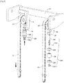
FIGS. 1 and2 are diagrams for describing a forklift according to an exemplary embodiment of the present invention. -
FIG. 3 is a diagram for describing a weight measuring unit in a forklift according to the exemplary embodiment of the present invention. - The advantages and characteristics of the present invention, and a method for achieving the advantages and characteristics will become clear by referring to the exemplary embodiment, which is described in detail, together with the accompanying drawings.
- Hereinafter, an exemplary embodiment of the present invention will be described in detail with reference to the accompanying drawings. The exemplary embodiment described below is illustrative for helping understanding of the present invention, and it shall be understood that and the present invention may be variously modified and carried out differently from the exemplary embodiment described herein. However, in the description of the present invention, when a detailed description of a related publicly known function or constituent element is determined to unnecessarily make the subject matter of the present invention unclear, the detailed description and a detailed illustration thereof will be omitted. Further, for helping the understanding of the invention, the accompanying drawings are not illustrated according to an actual scale, but sizes of some of the constituent elements may be exaggerated and illustrated.
- In the meantime, terms described below are terms set in consideration of a function in the present invention, and may be changed according to an intension of a producer or a usual practice, so that the definitions thereof should be made based on the entire contents of the present specification.
- Throughout the specification, the same reference numeral denotes the same constituent element.
- Hereinafter, a forklift according to an exemplary embodiment of the present invention will be described with reference to
FIGS. 1 to 3 . -
FIGS. 1 and2 are diagrams for describing a forklift according to an exemplary embodiment of the present invention.FIG. 3 is a diagram for describing a weight measuring unit in a forklift according to the exemplary embodiment of the present invention. - The forklift is provided with a
base frame 10, and amast frame 12 is provided in theframe 10 in a vertical direction. Further, atop frame 14 is disposed at an upper side of themast frame 12, and acarriage unit 40 is provided in a front direction of themast frame 12. - Further, a moving
frame 20 is provided inside themast frame 12 to be movable up and down, and aguide pulley 22 is provided in the movingframe 20. - Further, an
actuator 30 is installed in thebase frame 10, and the movingframe 20 is connected to a rod of theactuator 30. - In the meantime, one side of a
chain 50 is installed in thetop frame 14, and the other side of thechain 50 is installed in thecarriage unit 40 via theguide pulley 22. - That is, the moving
frame 20 moves up and down by an operation of theactuator 30, and thecarriage unit 40 moves up and down by the moving up and down operation of the movingframe 20. In addition, thechain 50 tows thecarriage unit 40 when the movingframe 20 moves up to raise thecarriage unit 40. In contrast, thechain 50 moves down thecarriage unit 40 by weight of thecarriage unit 40 when the movingframe 20 moves down. - In the forklift according to the exemplary embodiment of the present invention, a
weight measuring unit 100 is provided in a portion, in which thechain 50 is installed in thetop frame 14. Theweight measuring unit 100 is compressed by tensile force applied to thechain 50 and measures weight of a cargo W by a displacement changed during the compression. - Accordingly, the forklift according to the exemplary embodiment of the present invention converts the tensile force applied to the
chain 50 to compression force and converts the compression force to weight, and it is possible to measure weight of the cargo W within a remarkably short time compared to the related art, in which weight of a cargo is measured by measuring hydraulic pressure of a lift cylinder. - Further, the forklift according to the exemplary embodiment of the present invention measures a load directly applied to the
chain 50, so that it is possible to remarkably improve reliability compared to the related art, in which hydraulic pressure of a lift cylinder is measured. - Further, in the forklift according to the exemplary embodiment of the present invention, the
weight measuring unit 100 is disposed in an upper portion of the mast to maximally avoid interference with the cargo W or other things, so that it is possible to maximally prevent theweight measuring unit 100 from being damaged. - In the meantime, in the forklift according to the exemplary embodiment of the present invention, the
weight measuring unit 100 may be installed in asupport frame 16, which is formed in thetop frame 14, as illustrated inFIG. 3 . - The
supporter frame 16 may be formed in thetop frame 14, and ahole 18 may be formed in thesupporter frame 16 in a vertical direction. - A
shaft 102 is connected to thechain 50. Theshaft 102 is installed in thesupporter frame 16 so as to pass through thehole 18. That is, thechain 50 passes through theguide pulley 22, so that both end portions of thechain 50 head in a down direction. - A
rod cell 106 is installed to be penetrated by theshaft 102, which passes through thehole 18 of thesupporter frame 16. - Further, a
nut 110 is fastened to theshaft 102 which passes through therod cell 106. The tensile force applied to thechain 50 is applied in a direction of moving up theshaft 102 and thenut 110 is fastened to theshaft 102 and thus force is applied in a direction of moving up thenut 110 to finally compress therod cell 106. That is, therod cell 106 is operated by the tensile force applied to thechain 50 as compression stress. - In the meantime, the
rod cell 106 may have reliably lower durability than that of other constituent elements. That is, there is a probability that therod cell 106 is damaged by the tensile force applied to thechain 50. However, the forklift according to the exemplary embodiment of the present invention has the configuration that even when therod cell 106 is damaged, thechain 50 is not unwound, so that it is possible to more safely use the forklift. - In addition, even when the
rod cell 106 is damaged and separated due to an unexpected problem, thenut 110 is prevented from passing through thesupporter frame 16, so that thechain 50 is not loosened, thereby preventing an accident in which the cargo W is fallen. - On the other hand, the forklift according to the exemplary embodiment of the present invention may include first and
second columns rod cell 106, respectively. The first andsecond columns shaft 102. - Accordingly, in the forklift according to the exemplary embodiment of the present invention, tensile force applied to the
chain 50 is applied to therod cell 106 through thenut 110 as compression force, and in this case, thefirst column 104 helps thesupporter frame 16 and therod cell 106 to avoid direct friction to prevent therod cell 106 from being damaged. - Further, in the forklift according to the exemplary embodiment of the present invention, tensile force applied to the
chain 50 is applied to therod cell 106 through thenut 110 as compression force, and in this case, thesecond column 108 increases a contact area between thenut 110 and therod cell 106, so that it is possible to prevent compression force from being concentrated to a specific portion of therod cell 106 and distribute the compression force. That is, the compression force of an end portion of therod cell 106 is distributed, thereby preventing therod cell 106 from being damaged. - On the other hand, a
pin 112 may be further provided in an end portion of theshaft 102. Thepin 112 prevents thenut 110 from being arbitrarily loosened and separated. - The exemplary embodiments of the present invention have been described with reference to the accompanying drawings, but those skilled in the art may understand that the present invention may be carried out in another specific form without changing the technical spirit or an essential feature thereof.
- Accordingly, it will be understood that the aforementioned exemplary embodiments are described for illustrative and are not limited, and the scope of the present invention shall be represented by the claims to be described below, and all of the changes or modified forms induced from the meaning and the scope of the claims, and an equivalent concept thereof are included in the scope of the present invention.
- The forklift according to the exemplary embodiment of the present invention is usable for measuring a load applied to a fork.
-
10: Based frame 12: Mast frame 14: Top frame 16: Supporter frame 18: Hole 20: Moving frame 22: Guide pulley 30: Actuator 40: Carriage unit 50: Chain 100: Weight measuring unit 102: Shaft 104: First column 106: Rod cell 108: Second column 110: Nut 112: Pin
Claims (3)
- A forklift, comprising:a base frame (10);a mast frame (12) which is disposed in the base frame (10) in a vertical direction;a top frame (14) which is disposed at an upper side of the mast frame (12);a moving frame (20) which moves up and down in the mast frame (12);a guide pulley (22) provided in the moving frame (20);an actuator (30) which is installed in the base frame (10) and operates the moving frame (20) to move up and down;a carriage unit (40) which moves up and down in the mast frame (12);a chain (50) of which one side is installed in the top frame (14) and the other side is installed in the carriage unit (40) via the guide pulley (22); anda weight measuring unit (100) which is compressed by tensile force applied to the chain (50) in a portion, in which the chain (50) is installed in the top frame (14), and measures weight of a cargo by a displacement according to the compression.
- The forklift of claim 1, wherein the weight measuring unit (100) includes:a supporter frame (16) which is formed in the top frame (14) with a hole (18) in a vertical direction;a shaft (102) of which one side is connected to the chain (50) and the other side passes through the hole (18);a rod cell (106) which is installed to be penetrated by the shaft (102), which passes through the hole (18) of the supporter frame (16); anda nut (110) which is fastened to the shaft (102), which passes through the rod cell (106), to make tensile stress applied to the chain (50) act as pressure to the rod cell (106).
- The forklift of claim 2, further comprising:first and second columns (104 and 108) which are provided in the shaft (102) so as to be disposed at an upper side and a lower side of the rod cell (106), respectively.
Applications Claiming Priority (1)
| Application Number | Priority Date | Filing Date | Title |
|---|---|---|---|
| PCT/KR2015/013392 WO2017099269A1 (en) | 2015-12-08 | 2015-12-08 | Forklift |
Publications (2)
| Publication Number | Publication Date |
|---|---|
| EP3385213A1 true EP3385213A1 (en) | 2018-10-10 |
| EP3385213A4 EP3385213A4 (en) | 2019-08-14 |
Family
ID=59014277
Family Applications (1)
| Application Number | Title | Priority Date | Filing Date |
|---|---|---|---|
| EP15910295.3A Withdrawn EP3385213A4 (en) | 2015-12-08 | 2015-12-08 | FORK LIFT FORK |
Country Status (5)
| Country | Link |
|---|---|
| US (1) | US20190084815A1 (en) |
| EP (1) | EP3385213A4 (en) |
| JP (1) | JP2018536605A (en) |
| CN (1) | CN108473290A (en) |
| WO (1) | WO2017099269A1 (en) |
Families Citing this family (7)
| Publication number | Priority date | Publication date | Assignee | Title |
|---|---|---|---|---|
| CN112499524B (en) * | 2020-11-24 | 2023-01-06 | 宁波朗科称重设备有限公司 | Material lifting, carrying and metering logistics equipment |
| CN113955522A (en) * | 2021-09-13 | 2022-01-21 | 龙合智能装备制造有限公司 | Side position type intelligent loading equipment for stacked material loading |
| JP7697393B2 (en) * | 2022-03-29 | 2025-06-24 | 株式会社豊田自動織機 | forklift |
| CN116818072B (en) * | 2023-06-30 | 2026-05-01 | 浙江华睿科技股份有限公司 | Method and device for determining load weight, storage medium and electronic device |
| US20250388446A1 (en) * | 2024-06-20 | 2025-12-25 | Mitsubishi Logisnext Americas Inc. | Lift cylinder mounts for reducing a material handling vehicle's front overhang |
| US12600609B2 (en) | 2024-06-20 | 2026-04-14 | Mitsubishi Logisnext Americas Inc. | Hose supports for facilitating the assembly of masts for material handling vehicles and related methods |
| US20250388444A1 (en) * | 2024-06-20 | 2025-12-25 | Mitsubishi Logisnext Americas Inc. | Offset mast supports for coupling a mast to a material handling vehicle and related methods |
Family Cites Families (13)
| Publication number | Priority date | Publication date | Assignee | Title |
|---|---|---|---|---|
| GB1555598A (en) * | 1977-10-20 | 1979-11-14 | Pye Electronic Prod Ltd | Load measuring arrangements for fork lift trucks or the like |
| US4420053A (en) * | 1981-08-20 | 1983-12-13 | Litco International Inc. | Fork lift weighing apparatus |
| JPS613430U (en) * | 1984-06-12 | 1986-01-10 | 神鋼電機株式会社 | Forklift load detection mechanism |
| JP2507807Y2 (en) * | 1990-12-19 | 1996-08-21 | 日本輸送機株式会社 | Forklift load amount detection device |
| JP2524888Y2 (en) * | 1991-08-09 | 1997-02-05 | 小松フォークリフト株式会社 | Forklift truck working machine |
| KR19990018156A (en) * | 1997-08-26 | 1999-03-15 | 이충열 | Forklift danger warning system |
| JP2001026399A (en) * | 1999-07-16 | 2001-01-30 | Komatsu Forklift Co Ltd | Unbalanced load detector in cargo handling gear of forklift truck |
| US7026557B2 (en) * | 2003-10-30 | 2006-04-11 | Mettler-Toledo | Apparatus and method for weighting objects on a fork lift truck |
| KR200344391Y1 (en) * | 2003-12-05 | 2004-03-11 | 김문기 | scale device for forklift |
| CN201567185U (en) * | 2009-12-23 | 2010-09-01 | 艾云厂 | Engine-driven hydraulic fork truck with weighing function |
| US8779306B2 (en) * | 2010-02-19 | 2014-07-15 | Methode Electronics, Inc. | Weight sensing method and apparatus for forklifts |
| CN202046844U (en) * | 2011-04-19 | 2011-11-23 | 漆佳林 | Forklift weighing metering device |
| CN103964342A (en) * | 2014-04-29 | 2014-08-06 | 定远县明友墙体材料有限责任公司 | Special forklift for green bricks |
-
2015
- 2015-12-08 JP JP2018529563A patent/JP2018536605A/en active Pending
- 2015-12-08 WO PCT/KR2015/013392 patent/WO2017099269A1/en not_active Ceased
- 2015-12-08 CN CN201580085704.6A patent/CN108473290A/en active Pending
- 2015-12-08 US US16/060,045 patent/US20190084815A1/en not_active Abandoned
- 2015-12-08 EP EP15910295.3A patent/EP3385213A4/en not_active Withdrawn
Also Published As
| Publication number | Publication date |
|---|---|
| CN108473290A (en) | 2018-08-31 |
| JP2018536605A (en) | 2018-12-13 |
| US20190084815A1 (en) | 2019-03-21 |
| EP3385213A4 (en) | 2019-08-14 |
| WO2017099269A1 (en) | 2017-06-15 |
Similar Documents
| Publication | Publication Date | Title |
|---|---|---|
| US20190084815A1 (en) | Forklift | |
| CN103663293B (en) | Little tonnage electri forklift is with certainly clamping goods shelf | |
| CN102887406A (en) | Elevator load detection device and method thereof | |
| CN106049394A (en) | Control method and control system of hydraulic bolt type lifting equipment | |
| KR102775970B1 (en) | Locking device for a forming tool including a first tool member and a second tool member and Forming tool including the same | |
| CN104828742A (en) | Intelligent and safe lifting base | |
| CN101428676B (en) | Boat body section jacking apparatus | |
| CN104649138B (en) | Straddle carrier | |
| CN204897307U (en) | A lifting pedestal for producing coil of strip is packed with interior exterior angle circle | |
| CN105174153A (en) | Hydraulic buffering protective lifting platform | |
| CN103693570B (en) | Super lifting device, crane and control method thereof | |
| CN105417455A (en) | Hydraulic climbing mechanism | |
| CN204434234U (en) | A kind of overload rope-loosing protection device | |
| CN112441521A (en) | Lifting belt clamping device and lifting machine | |
| CN107790604A (en) | Automobile trunk hinge automatic riveting machine | |
| KR20160061634A (en) | Forklift | |
| US20160068378A1 (en) | Chain hoist | |
| CN204416850U (en) | A kind of lifting structure of elevator | |
| US20140360283A1 (en) | Padeye tester | |
| CN213297867U (en) | A kind of upper and lower limit anti-collision device of pneumatic casing centralizer | |
| CN205655849U (en) | Pressurization unit of sensor | |
| KR102192118B1 (en) | An Automatic Detection Type of a Load Detecting Apparatus for a Number of Wire in a Crane | |
| CN203667859U (en) | Super lifting device and its crane | |
| CN209085513U (en) | Spring steel lateral bending straightness detection instrument | |
| CN108223485A (en) | A kind of lathe hydraulic cylinder that automatically resets |
Legal Events
| Date | Code | Title | Description |
|---|---|---|---|
| STAA | Information on the status of an ep patent application or granted ep patent |
Free format text: STATUS: THE INTERNATIONAL PUBLICATION HAS BEEN MADE |
|
| PUAI | Public reference made under article 153(3) epc to a published international application that has entered the european phase |
Free format text: ORIGINAL CODE: 0009012 |
|
| STAA | Information on the status of an ep patent application or granted ep patent |
Free format text: STATUS: REQUEST FOR EXAMINATION WAS MADE |
|
| 17P | Request for examination filed |
Effective date: 20180706 |
|
| AK | Designated contracting states |
Kind code of ref document: A1 Designated state(s): AL AT BE BG CH CY CZ DE DK EE ES FI FR GB GR HR HU IE IS IT LI LT LU LV MC MK MT NL NO PL PT RO RS SE SI SK SM TR |
|
| AX | Request for extension of the european patent |
Extension state: BA ME |
|
| DAV | Request for validation of the european patent (deleted) | ||
| DAX | Request for extension of the european patent (deleted) | ||
| REG | Reference to a national code |
Ref country code: DE Ref legal event code: R079 Free format text: PREVIOUS MAIN CLASS: B66F0009075000 Ipc: B66F0017000000 |
|
| A4 | Supplementary search report drawn up and despatched |
Effective date: 20190716 |
|
| RIC1 | Information provided on ipc code assigned before grant |
Ipc: G01G 19/08 20060101ALI20190710BHEP Ipc: B66F 9/08 20060101ALI20190710BHEP Ipc: B66F 17/00 20060101AFI20190710BHEP |
|
| RAP1 | Party data changed (applicant data changed or rights of an application transferred) |
Owner name: DOOSAN INDUSTRIAL VEHICLE CO., LTD. |
|
| RAP1 | Party data changed (applicant data changed or rights of an application transferred) |
Owner name: DOOSAN INDUSTRIAL VEHICLE CO., LTD. |
|
| STAA | Information on the status of an ep patent application or granted ep patent |
Free format text: STATUS: EXAMINATION IS IN PROGRESS |
|
| 17Q | First examination report despatched |
Effective date: 20220914 |
|
| STAA | Information on the status of an ep patent application or granted ep patent |
Free format text: STATUS: THE APPLICATION IS DEEMED TO BE WITHDRAWN |
|
| 18D | Application deemed to be withdrawn |
Effective date: 20230125 |