EP3385098A1 - Vehicle stabilizer device - Google Patents
Vehicle stabilizer device Download PDFInfo
- Publication number
- EP3385098A1 EP3385098A1 EP16870621.6A EP16870621A EP3385098A1 EP 3385098 A1 EP3385098 A1 EP 3385098A1 EP 16870621 A EP16870621 A EP 16870621A EP 3385098 A1 EP3385098 A1 EP 3385098A1
- Authority
- EP
- European Patent Office
- Prior art keywords
- bush
- stabilizer
- adhesive
- rubber
- display portion
- Prior art date
- Legal status (The legal status is an assumption and is not a legal conclusion. Google has not performed a legal analysis and makes no representation as to the accuracy of the status listed.)
- Granted
Links
Images


Classifications
-
- B—PERFORMING OPERATIONS; TRANSPORTING
- B60—VEHICLES IN GENERAL
- B60G—VEHICLE SUSPENSION ARRANGEMENTS
- B60G21/00—Interconnection systems for two or more resiliently-suspended wheels, e.g. for stabilising a vehicle body with respect to acceleration, deceleration or centrifugal forces
- B60G21/02—Interconnection systems for two or more resiliently-suspended wheels, e.g. for stabilising a vehicle body with respect to acceleration, deceleration or centrifugal forces permanently interconnected
- B60G21/04—Interconnection systems for two or more resiliently-suspended wheels, e.g. for stabilising a vehicle body with respect to acceleration, deceleration or centrifugal forces permanently interconnected mechanically
- B60G21/05—Interconnection systems for two or more resiliently-suspended wheels, e.g. for stabilising a vehicle body with respect to acceleration, deceleration or centrifugal forces permanently interconnected mechanically between wheels on the same axle but on different sides of the vehicle, i.e. the left and right wheel suspensions being interconnected
- B60G21/055—Stabiliser bars
-
- B—PERFORMING OPERATIONS; TRANSPORTING
- B60—VEHICLES IN GENERAL
- B60G—VEHICLE SUSPENSION ARRANGEMENTS
- B60G21/00—Interconnection systems for two or more resiliently-suspended wheels, e.g. for stabilising a vehicle body with respect to acceleration, deceleration or centrifugal forces
- B60G21/02—Interconnection systems for two or more resiliently-suspended wheels, e.g. for stabilising a vehicle body with respect to acceleration, deceleration or centrifugal forces permanently interconnected
- B60G21/04—Interconnection systems for two or more resiliently-suspended wheels, e.g. for stabilising a vehicle body with respect to acceleration, deceleration or centrifugal forces permanently interconnected mechanically
- B60G21/05—Interconnection systems for two or more resiliently-suspended wheels, e.g. for stabilising a vehicle body with respect to acceleration, deceleration or centrifugal forces permanently interconnected mechanically between wheels on the same axle but on different sides of the vehicle, i.e. the left and right wheel suspensions being interconnected
- B60G21/055—Stabiliser bars
- B60G21/0551—Mounting means therefor
-
- F—MECHANICAL ENGINEERING; LIGHTING; HEATING; WEAPONS; BLASTING
- F16—ENGINEERING ELEMENTS AND UNITS; GENERAL MEASURES FOR PRODUCING AND MAINTAINING EFFECTIVE FUNCTIONING OF MACHINES OR INSTALLATIONS; THERMAL INSULATION IN GENERAL
- F16F—SPRINGS; SHOCK-ABSORBERS; MEANS FOR DAMPING VIBRATION
- F16F1/00—Springs
- F16F1/36—Springs made of rubber or other material having high internal friction, e.g. thermoplastic elastomers
- F16F1/373—Springs made of rubber or other material having high internal friction, e.g. thermoplastic elastomers characterised by having a particular shape
- F16F1/3732—Springs made of rubber or other material having high internal friction, e.g. thermoplastic elastomers characterised by having a particular shape having an annular or the like shape, e.g. grommet-type resilient mountings
- F16F1/3735—Multi-part grommet-type resilient mountings
-
- B—PERFORMING OPERATIONS; TRANSPORTING
- B60—VEHICLES IN GENERAL
- B60G—VEHICLE SUSPENSION ARRANGEMENTS
- B60G2202/00—Indexing codes relating to the type of spring, damper or actuator
- B60G2202/10—Type of spring
- B60G2202/13—Torsion spring
- B60G2202/135—Stabiliser bar and/or tube
-
- B—PERFORMING OPERATIONS; TRANSPORTING
- B60—VEHICLES IN GENERAL
- B60G—VEHICLE SUSPENSION ARRANGEMENTS
- B60G2204/00—Indexing codes related to suspensions per se or to auxiliary parts
- B60G2204/10—Mounting of suspension elements
- B60G2204/12—Mounting of springs or dampers
- B60G2204/122—Mounting of torsion springs
- B60G2204/1222—Middle mounts of stabiliser on vehicle body or chassis
-
- B—PERFORMING OPERATIONS; TRANSPORTING
- B60—VEHICLES IN GENERAL
- B60G—VEHICLE SUSPENSION ARRANGEMENTS
- B60G2204/00—Indexing codes related to suspensions per se or to auxiliary parts
- B60G2204/40—Auxiliary suspension parts; Adjustment of suspensions
- B60G2204/41—Elastic mounts, e.g. bushings
-
- B—PERFORMING OPERATIONS; TRANSPORTING
- B60—VEHICLES IN GENERAL
- B60G—VEHICLE SUSPENSION ARRANGEMENTS
- B60G2206/00—Indexing codes related to the manufacturing of suspensions: constructional features, the materials used, procedures or tools
- B60G2206/01—Constructional features of suspension elements, e.g. arms, dampers, springs
- B60G2206/40—Constructional features of dampers and/or springs
- B60G2206/42—Springs
- B60G2206/427—Stabiliser bars or tubes
-
- B—PERFORMING OPERATIONS; TRANSPORTING
- B60—VEHICLES IN GENERAL
- B60G—VEHICLE SUSPENSION ARRANGEMENTS
- B60G2206/00—Indexing codes related to the manufacturing of suspensions: constructional features, the materials used, procedures or tools
- B60G2206/01—Constructional features of suspension elements, e.g. arms, dampers, springs
- B60G2206/80—Manufacturing procedures
- B60G2206/82—Joining
- B60G2206/821—Joining by gluing
-
- F—MECHANICAL ENGINEERING; LIGHTING; HEATING; WEAPONS; BLASTING
- F16—ENGINEERING ELEMENTS AND UNITS; GENERAL MEASURES FOR PRODUCING AND MAINTAINING EFFECTIVE FUNCTIONING OF MACHINES OR INSTALLATIONS; THERMAL INSULATION IN GENERAL
- F16F—SPRINGS; SHOCK-ABSORBERS; MEANS FOR DAMPING VIBRATION
- F16F2226/00—Manufacturing; Treatments
- F16F2226/04—Assembly or fixing methods; methods to form or fashion parts
- F16F2226/042—Gluing
-
- F—MECHANICAL ENGINEERING; LIGHTING; HEATING; WEAPONS; BLASTING
- F16—ENGINEERING ELEMENTS AND UNITS; GENERAL MEASURES FOR PRODUCING AND MAINTAINING EFFECTIVE FUNCTIONING OF MACHINES OR INSTALLATIONS; THERMAL INSULATION IN GENERAL
- F16F—SPRINGS; SHOCK-ABSORBERS; MEANS FOR DAMPING VIBRATION
- F16F2230/00—Purpose; Design features
- F16F2230/0005—Attachment, e.g. to facilitate mounting onto confer adjustability
-
- F—MECHANICAL ENGINEERING; LIGHTING; HEATING; WEAPONS; BLASTING
- F16—ENGINEERING ELEMENTS AND UNITS; GENERAL MEASURES FOR PRODUCING AND MAINTAINING EFFECTIVE FUNCTIONING OF MACHINES OR INSTALLATIONS; THERMAL INSULATION IN GENERAL
- F16F—SPRINGS; SHOCK-ABSORBERS; MEANS FOR DAMPING VIBRATION
- F16F2230/00—Purpose; Design features
- F16F2230/0047—Measuring, indicating
Definitions
- the present invention relates to a vehicle stabilizer device comprising a rubber bush arranged in a suspension mechanism part of a vehicle such as a car.
- a stabilizer device arranged in a suspension mechanism part of a vehicle includes a stabilizer formed of a steel pipe or a solid rod-shaped steel material, as described in, for example, Patent Literature 1 or Patent Literature 2.
- the stabilizer is supported on a vehicle body via a support portion.
- the stabilizer includes a torsion portion extending in a width direction of the vehicle, a pair of arm portions which are continuous with both ends of the torsion portion via bent portions, and eye portions formed at distal ends of the respective arm portions.
- the support portion is a pair of bush units comprising rubber bushes.
- the torsion portion of the stabilizer is supported on the vehicle body via the bush unit.
- the eye portion is connected to a suspension arm, etc., via a connecting member such as a stabilizer link.
- a connecting member such as a stabilizer link.
- the form of the stabilizer device is various according to the suspension mechanism part of the vehicle.
- a type (bush-bonding-type) in which the rubber bush is bonded to the stabilizer and a type (bush-unbonded-type) in which the rubber bush is not bonded to the stabilizer are known.
- the rubber bush In the bush-bonding-type, the rubber bush is also twisted and deformed when the stabilizer is twisted. Since a frictional surface does not exist between the stabilizer and the rubber bush in the bush-bonding-type stabilizer device, there is no fear of causing abnormal sound.
- a contact surface between the stabilizer and the rubber bush slides when the stabilizer is twisted.
- an adhesive 3 is applied by spraying, etc., for a length L1 on a surface of a torsion portion 2, at the convenience of a production line, for example.
- a rubber bush 4 is placed on the adhesive 3.
- the adhesive 3 is cured for a predetermined time. In this way, the adhesive 3 is cured, and the rubber bush 4 is fixed to the stabilizer 1.
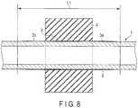
- the adhesive 3 is applied to a relatively large area on the surface of the torsion portion 2. Moreover, parts 3a and 3b of the adhesive 3 is exposed on the surface of the stabilizer 1 on the outer side of the rubber bush 4. Accordingly, even after the rubber bush 4 has been placed over the stabilizer 1, whether or not the adhesive 3 is applied can be visually checked from outside. However, since the parts 3a and 3b of the adhesive 3 stick on a wide range of the surface of the stabilizer 1, the outer appearance of the stabilizer 1 may be deteriorated. Moreover, a problem that the adhesive 3 is used largely arises.
- a portion where the adhesive is applied has conventionally been heated by high-frequency induction heating, etc., from outside the rubber bush 4 in a state where the rubber bush 4 is placed over the stabilizer 1. Accordingly, not only does the heating take time, but there also arises a problem that the temperature control of the portion where the adhesive is applied is difficult.
- an object of the present invention is to provide a vehicle stabilizer device for which the presence or absence of an adhesion layer can be checked even after a rubber bush has been placed over a stabilizer, in which an area for applying an adhesion member is small, and for which an increase in the amount of use of the adhesion member can be suppressed.
- a vehicle stabilizer device including a stabilizer extending in a width direction of a vehicle, and a bush unit provided on a support portion of the stabilizer, in which the bush unit includes a bracket formed of metal, a rubber bush, an adhesion layer formed of an adhesion member, and a bonding display portion formed of a part of the adhesion member.
- the rubber bush is formed of a plurality of bush pieces arranged inside the bracket. Further, the rubber bush includes a hole through which the stabilizer passes.
- the adhesion layer is provided between an inner surface of the hole of the rubber bush and the stabilizer.
- the adhesion member includes an adhesive formed on the inner surface of the hole, and a primer layer formed on the adhesive.
- the bonding display portion is provided at a corner on an end face of the bush piece near the inner surface, sticks to the end face, and can be visually checked from outside the rubber bush.
- bonding display portion is formed of at least one of the adhesive and the primer layer. Further, the bonding display portion may be formed at a part of the hole in a circumferential direction thereof at the corner. Alternatively, the bonding display portion may be formed on the entire periphery of the hole at the corner.
- the present invention even after the rubber bush has been mounted on the stabilizer, by visually checking the presence or absence of the bonding display portion, it is possible to check whether the adhesion layer is provided between the rubber bush and the stabilizer. Thus, a defect that the adhesion layer is not provided by mistake in the case of a bush-bonding-type device can be found.
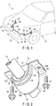
- a vehicle stabilizer device 10 according to a first embodiment will be described with reference to FIGS. 1 to 6 .
- FIG. 1 shows a part of a vehicle 11 comprising the stabilizer device 10.
- the stabilizer device 10 is arranged in a suspension mechanism part of the vehicle 11.
- the stabilizer device 10 includes a stabilizer 20, and a support portion 21.
- the stabilizer 20 is formed of a rod-shaped spring steel (steel material) extending in a width direction (i.e., a direction indicated by arrow W) of a vehicle body 12.
- the support portion 21 supports the stabilizer 20 on the vehicle body 12.
- An example of the support portion 21 comprises a pair of bush units 22 and 23.
- the stabilizer 20 includes a torsion portion 30, bent portions 31 and 32, and arm portions 33 and 34.
- the torsion portion 30 extends in the width direction (i.e., the direction indicated by arrow W) of the vehicle body 12.
- the arm portions 33 and 34 are continuous with both ends of the torsion portion 30 through their corresponding bent portions 31 and 32.
- eye portions 35 and 36 are formed, respectively.
- the eye portions 35 and 36 are connected to suspension arms of the suspension mechanism part, for example, through connecting members 37 and 38 such as stabilizer links.
- the stabilizer 20 of the present embodiment is hollow.
- a material of the stabilizer 20 which is hollow is a steel pipe. By bending the steel pipe by a bending machine, the steel pipe is formed into a predetermined shape.
- a solid stabilizer may be adopted.
- a material of the solid stabilizer is a steel rod.
- the shape of the stabilizer 20 is not limited to planar.
- the stabilizer 20 may include one or more bending portions in the torsion portion 30, or one or more bending portions in the arm portions 33 and 34, including a three-dimensional bent configuration.
- the bent portions 31 and 32 may be configured to have a three-dimensional bent configuration, for example, and can be formed into various bent shapes according to the specifications of the suspension mechanism part.
- a resin-based coating film 40 ( FIGS. 3 and 4 ) is provided on a surface of the stabilizer 20 .
- the coating film 40 is formed of, for example, epoxy resin, to serve the purpose of preventing rust, mainly, and in consideration of the appearance quality as well.
- a compressive residual stress is applied to a surface layer portion including the surface of the stabilizer 20 by shot peening.
- the torsion portion 30 of the stabilizer 20 is supported on a part of the vehicle body 12 (such as a cross-member), for example, via the bush units 22 and 23.
- Forces having opposite phases are input to the arm portions 33 and 34, such as when the vehicle 11 drives on a curve.
- a bending force is exerted on the arm portions 33 and 34, and bending and torsional force is exerted on the bent portions 31 and 32.
- a repulsive load is produced by the torsion portion 30 being twisted, for example, a rolling behavior of the vehicle body 12 is suppressed.
- FIGS. 2 to 4 show the bush unit 22.
- the bush unit 22 comprises a metal bracket 50, and a rubber bush 60 disposed inside the bracket 50.
- the stabilizer device 10 of the present embodiment is of a bush-bonding-type in which the rubber bush 60 is bonded to the stabilizer 20.
- the bracket 50 includes a cover portion 50a, and a pair of arm portions 50b and 50c.
- the cover portion 50a is shaped such that it encompasses the rubber bush 60 (i.e., substantially U-shaped).
- the arm portions 50b and 50c are formed on both sides of the cover portion 50a.
- holes 53 and 54 for inserting bolts 51 and 52 therein are formed, respectively.
- the bush unit 22 is mounted on the suspension mechanism part from the lower side or upper side of the vehicle by the bolts 51 and 52.
- the rubber bush 60 is not limited to the present embodiment, an example of the rubber bush 60 shown in FIG. 5 is in the shape of two divided parts.
- the rubber bush 60 is comprised of a pair of two divided parts, i.e., a first bush piece 61 and a second bush piece 62.
- Each of the first bush piece 61 and the second bush piece 62 is formed of a material having rubber elasticity.
- An example of the material is formed of kneaded rubber of NR and IIR.
- the kneaded rubber intended here refers to a blended rubber formed of natural rubber and synthetic rubber such as butyl rubber.
- a hole 63 through which the stabilizer 20 passes is formed.
- the stabilizer 20 is arranged between the first bush piece 61 and the second bush piece 62.
- the bush pieces 61 and 62 are fixed to the stabilizer 20 via an adhesion layer 70 ( FIGS. 3 and 4 ).
- the first bush piece 61 and the second bush piece 62 are covered by the cover portion 50a of the bracket 50 which serves as a housing.
- each of the inner surfaces 64 and 65 is slightly smaller than the outer diameter of the torsion portion 30.
- the adhesion layer 70 is provided on each of the inner surfaces 64 and 65 of the bush pieces 61 and 62.
- the adhesion layer 70 is comprised of an adhesion member 73 including an adhesive 71 and a primer layer 72.
- the adhesive 71 is applied to the inner surfaces 64 and 65 of the bush pieces 61 and 62.
- the primer layer 72 is applied on the adhesive 71.
- the thickness of the adhesion layer 70 (the total thickness of the adhesive 71 and the primer layer 72) is 20 to 100 ⁇ m.
- the thickness of the adhesive 71 is 10 to 70 ⁇ m
- the thickness of the primer layer 72 is 10 to 30 pm.
- the thickness of the adhesion layer 70 is less than that of the above range, adhesion failure is likely to occur. Conversely, if the thickness of the adhesion layer 70 is greater than that of the above range, process time needed for adhesion becomes longer, and a waste on the material of the adhesion layer 70 is incurred.
- the adhesive 71 comprises a polyolefin resin and a solvent, and as the adhesive is heated to a temperature of 140 to 170°C, for example, the solvent is vaporized and the adhesive is cured.
- the primer layer 72 is used for increasing the adhesion to the coating film 40.
- the primer layer 72 is formed of a material (for example, a phenolic resin) having better adhesiveness to the coating film 40 than the adhesive 71.
- a bonding display portion 80 is provided at part of end faces 66 and 67 of the first bush piece 61 (corners C1 and C2 near the inner surface 64). Also at part of end faces 68 and 69 of the second bush piece 62 (corners C3 and C4 near the inner surface 65), the bonding display portion 80 is formed. These bonding display portions 80 may be provided at all of the corners C1 to C4 on the end faces 66 to 69. Alternatively, the bonding display portion 80 may be provided on only the selected end face of the end faces 66 to 69.
- the bonding display portion 80 is formed of a part of the adhesion member 73 (an end portion of the adhesion layer 70). That is, the bonding display portion 80 is formed of at least one of the adhesive 71 and the primer layer 72.
- the bonding display portion 80 shown in FIG. 4 is formed of a part of the adhesive 71 and a part of the primer layer 72.
- the bonding display portion 80 may be formed at a part of the hole 63 in a circumferential direction thereof, or on the entire circumference of the hole 63.
- the bonding display portion 80 is formed in at least a part of the corners C1, C2, C3, and C4 on the end faces 66, 67, 68, and 69.
- the adhesive 71 and the primer layer 72 are applied to the inner surfaces 64 and 65 of the bush pieces 61 and 62, parts of the adhesive 71 and the primer layer 72 are made to protrude on at least one place of the end faces 66, 67, 68, and 69, and cured. Consequently, the bonding display portion 80 sticks to at least a part of the end faces 66, 67, 68, and 69.
- the bonding display portion 80 is provided on at least one place of the end faces of the rubber bush 60. Accordingly, even after the rubber bush 60 has been placed over the stabilizer 20, the bonding display portion 80 can be visually checked from outside the rubber bush 60.
- the first bush piece 61 and the second bush piece 62 are arranged in such a state that the inner surfaces 64 and 65 face upward. Further, the adhesion layer 70 is provided on each of the inner surfaces 64 and 65. More specifically, the adhesive 71 in liquid form is applied to the inner surfaces 64 and 65. When the applied adhesive 71 is cured to some degree, the primer layer 72 in liquid form is applied on the adhesive 71. When the adhesive 71 and the primer layer 72 are applied, at least one of the adhesive 71 and the primer layer 72 is stuck at the corners C1 and C2 of the first bush piece 61 or the corners C3 and C4 of the second bush piece 62.
- a region including a bush bonding portion (a part where the rubber bush 60 is bonded) of the stabilizer 20 is heated to a predetermined temperature (200°C or lower).
- a predetermined temperature 200°C or lower.
- the stabilizer 20 is heated by high-frequency induction heating, for example.
- the heated stabilizer 20 is kept at a curing temperature (for example, 110 to 170°C) of the adhesion layer 70. In this temperature range, the inner surfaces 64 and 65 of the first bush piece 61 and the second bush piece 62 are brought to overlap the bush bonding portion of the stabilizer 20. Further, the bush pieces 61 and 62 are clamped from both sides and pressurized.
- the adhesion layer 70 is heated by the heat of the stabilizer 20.
- the adhesion layer 70 is cured in a temperature range (for example, 110 to 170°C) in which the adhesive 71 is cured.
- the solvent is vaporized and curing takes place. In this way, the first bush piece 61 and the second bush piece 62 are bonded to the stabilizer 20. Note that when the heating temperature of the adhesion layer 70 is lower than the temperature of the above range, adhesion failure may occur.
- the coating film 40 may be deteriorated, and the durability may be decreased. Further, if the heating temperature is higher than the temperature of the above range, a compressive residual stress imparted to the surface layer portion of the stabilizer 20 in advance by shot peening is sometimes not maintained.
- the primer layer is applied to a surface of the stabilizer first. After that, the adhesive is applied on the primer layer. Further, it is common to place the rubber bush on the adhesive. Accordingly, in a conventional bush-bonding-type stabilizer, the adhesive does not stick on an end face of the rubber bush.
- the adhesive 71 and the primer layer 72 are applied to the inner surfaces 64 and 65 of the bush pieces 61 and 62. Accordingly, the bonding display portion 80 comprising at least one of the adhesive 71 and the primer layer 72 can be formed at the corners C1 to C4 on the end faces 66 to 69 of the rubber bush 60.
- the bonding display portion 80 is provided in at least one place of the corners C1 to C4 around the hole 63 on the end face of the rubber bush 60. Accordingly, even after the rubber bush 60 has been mounted on the stabilizer 20, by visually checking the presence or absence of the bonding display portion 80, it is possible to determine whether the adhesion layer 70 exists between the stabilizer 20 and the rubber bush 60.
- a defective product which is a device not provided with the adhesion layer 70 between stabilizer 20 and the rubber bush 60, can be found by visual inspection.
- a defective product which is a device erroneously provided with an adhesion layer provided between the stabilizer and the rubber bush, can be found by checking the bonding display portion 80.
- the bush bonding portion in a longitudinal direction thereof (i.e., the bush bonding portion) is heated by induction heating or the like. Accordingly, as compared to a case of heating the bush bonding portion indirectly from outside, in a state where the rubber bush is placed over the stabilizer, as has been performed conventionally, the heating time can be shortened, and controlling the temperature of the bush bonding portion is easier.
- the adhesive 71 and the primer layer 72 are applied to only the rubber bush 60.
- a range of application of the adhesion member 73 is substantially a length L2 ( FIG. 3 ) of the rubber bush 60. Accordingly, according to the stabilizer device 10 of the present embodiment, the amount of use of the adhesion member 73 can be greatly reduced, as compared to a conventional application range L1 shown in FIG. 8 .
- the adhesion member 73 does not stick to a portion other than the bush bonding portion. Accordingly, a problem that the outer appearance of the stabilizer 20 impaired by the adhesion member sticking on the surface of the stabilizer 20 does not arise.
- the bonding display portion 80 formed at the corners C1 to C4 of the bush pieces 61 and 62 may be formed around at least a part of the hole 63 in the circumferential direction thereof. Alternatively, the bonding display portion 80 may be formed on the entire periphery of the hole 63. When the bonding display portion 80 is formed on the entire periphery of the hole 63, the bonding display portion 80 is able to block (suppress) oil or moisture, etc., making its way into the rubber bush 60 along the surface of the stabilizer 20.
- FIG. 7 shows a rubber bush 60' according to a second embodiment.
- a first bush piece 61 and a second bush piece 62 are connected to each other via a hinge portion 90.
- one of the bush pieces of the first bush piece 61 and the second bush piece 62 is folded over the other bush piece along the hinge portion 90 to sandwich the stabilizer between inner surfaces 64 and 65.
- common reference numerals are added to parts that are in common, and explanations of those parts will be omitted.
- a steel material which is the material of the stabilizer, may be a solid material other than a hollow material (a steel pipe). Further, a core made of an iron plate or synthetic resin for adjusting the stiffness, etc., may be inserted into the rubber bush, and the number of dividing the rubber bush (the number of bush pieces) may be greater than two (for example, three).
- 10 ⁇ Stabilizer device 20 ⁇ Stabilizer, 21 ⁇ Support portion, 22, 23 ⁇ Bush unit, 40 ⁇ Coating film, 50 ⁇ Bracket, 60 ⁇ Rubber bush, 61 ⁇ First bush piece, 62 ⁇ Second bush piece, 63 ⁇ Hole, 64, 65 ⁇ Inner surface, 66, 67 ⁇ End face, 68, 69 ⁇ End face, 71 ⁇ Adhesive, 72 ⁇ Primer layer, 73 ⁇ Adhesion member, 80 ⁇ Bonding display portion, C1, C2, C3, C4 ⁇ Corner
Landscapes
- Engineering & Computer Science (AREA)
- Mechanical Engineering (AREA)
- General Engineering & Computer Science (AREA)
- Vehicle Body Suspensions (AREA)
Abstract
Description
- The present invention relates to a vehicle stabilizer device comprising a rubber bush arranged in a suspension mechanism part of a vehicle such as a car.
- A stabilizer device arranged in a suspension mechanism part of a vehicle includes a stabilizer formed of a steel pipe or a solid rod-shaped steel material, as described in, for example,
Patent Literature 1 orPatent Literature 2. The stabilizer is supported on a vehicle body via a support portion. The stabilizer includes a torsion portion extending in a width direction of the vehicle, a pair of arm portions which are continuous with both ends of the torsion portion via bent portions, and eye portions formed at distal ends of the respective arm portions. - An example of the support portion is a pair of bush units comprising rubber bushes. The torsion portion of the stabilizer is supported on the vehicle body via the bush unit. The eye portion is connected to a suspension arm, etc., via a connecting member such as a stabilizer link. With respect to the stabilizer device mounted in the vehicle, as the arm portions, the bent portions, and the torsion portion function as a spring in reaction to a rolling behavior of the vehicle body, roll stiffness of the vehicle can be enhanced.
- The form of the stabilizer device is various according to the suspension mechanism part of the vehicle. For example, a type (bush-bonding-type) in which the rubber bush is bonded to the stabilizer, and a type (bush-unbonded-type) in which the rubber bush is not bonded to the stabilizer are known. In the bush-bonding-type, the rubber bush is also twisted and deformed when the stabilizer is twisted. Since a frictional surface does not exist between the stabilizer and the rubber bush in the bush-bonding-type stabilizer device, there is no fear of causing abnormal sound. In contrast, in the bush-unbonded-type stabilizer device, a contact surface between the stabilizer and the rubber bush slides when the stabilizer is twisted.
- In the case of manufacturing the bush-bonding-type stabilizer device in large quantities, as in a
stabilizer 1 shown inFIG. 8 , for example, anadhesive 3 is applied by spraying, etc., for a length L1 on a surface of atorsion portion 2, at the convenience of a production line, for example. After that, arubber bush 4 is placed on theadhesive 3. In this state, by heating thestabilizer 1 together with pressurizing therubber bush 4 from both sides, theadhesive 3 is cured for a predetermined time. In this way, theadhesive 3 is cured, and therubber bush 4 is fixed to thestabilizer 1. -
- Patent Literature 1:
JP H01-175906 U - Patent Literature 2:
JP 2002-264625 A - In a
conventional stabilizer 1 shown inFIG. 8 , theadhesive 3 is applied to a relatively large area on the surface of thetorsion portion 2. Moreover,parts adhesive 3 is exposed on the surface of thestabilizer 1 on the outer side of therubber bush 4. Accordingly, even after therubber bush 4 has been placed over thestabilizer 1, whether or not theadhesive 3 is applied can be visually checked from outside. However, since theparts stabilizer 1, the outer appearance of thestabilizer 1 may be deteriorated. Moreover, a problem that theadhesive 3 is used largely arises. Further, a portion where the adhesive is applied has conventionally been heated by high-frequency induction heating, etc., from outside therubber bush 4 in a state where therubber bush 4 is placed over thestabilizer 1. Accordingly, not only does the heating take time, but there also arises a problem that the temperature control of the portion where the adhesive is applied is difficult. - Hence, one idea was to apply the adhesive on an inner surface of the rubber bush (the surface in contact with the stabilizer). However, in such a case, after placing the rubber bush over the stabilizer, the adhesive is hidden inside the rubber bush. Accordingly, whether or not the adhesive is applied (presence of an adhesion layer) could not be visually checked. Consequently, it is possible that a defective product not having an adhesive applied to a rubber bush by mistake even though it should have been used for a bush-bonding-type stabilizer will be overlooked. Conversely, it is possible that a defective product having an adhesive applied to a rubber bush by mistake even though it should have been used for a bush-unbonded-type stabilizer will be overlooked.
- Accordingly, an object of the present invention is to provide a vehicle stabilizer device for which the presence or absence of an adhesion layer can be checked even after a rubber bush has been placed over a stabilizer, in which an area for applying an adhesion member is small, and for which an increase in the amount of use of the adhesion member can be suppressed.
- One embodiment relates to a vehicle stabilizer device including a stabilizer extending in a width direction of a vehicle, and a bush unit provided on a support portion of the stabilizer, in which the bush unit includes a bracket formed of metal, a rubber bush, an adhesion layer formed of an adhesion member, and a bonding display portion formed of a part of the adhesion member. The rubber bush is formed of a plurality of bush pieces arranged inside the bracket. Further, the rubber bush includes a hole through which the stabilizer passes. The adhesion layer is provided between an inner surface of the hole of the rubber bush and the stabilizer. The adhesion member includes an adhesive formed on the inner surface of the hole, and a primer layer formed on the adhesive. The bonding display portion is provided at a corner on an end face of the bush piece near the inner surface, sticks to the end face, and can be visually checked from outside the rubber bush.
- An example of the bonding display portion is formed of at least one of the adhesive and the primer layer. Further, the bonding display portion may be formed at a part of the hole in a circumferential direction thereof at the corner. Alternatively, the bonding display portion may be formed on the entire periphery of the hole at the corner.
- According to the present invention, even after the rubber bush has been mounted on the stabilizer, by visually checking the presence or absence of the bonding display portion, it is possible to check whether the adhesion layer is provided between the rubber bush and the stabilizer. Thus, a defect that the adhesion layer is not provided by mistake in the case of a bush-bonding-type device can be found.
-
-
FIG. 1 is a perspective view schematically showing a part of a vehicle and a stabilizer device. -
FIG. 2 is a perspective view of a part of a stabilizer device according to a first embodiment. -
FIG. 3 is a cross-sectional view of a part of the stabilizer device shown inFIG. 2 in an axial direction thereof. -
FIG. 4 is a cross-sectional view showing a part of the stabilizer device in an enlarged scale. -
FIG. 5 is an exploded perspective view of a rubber bush of the stabilizer device. -
FIG. 6 is a perspective view of a first bush piece and a second bush piece of the rubber bush shown inFIG. 5 arranged side by side. -
FIG. 7 is a perspective view of a rubber bush according to a second embodiment. -
FIG. 8 is a cross-sectional view schematically showing a conventional stabilizer device. - A
vehicle stabilizer device 10 according to a first embodiment will be described with reference toFIGS. 1 to 6 . -
FIG. 1 shows a part of avehicle 11 comprising thestabilizer device 10. Thestabilizer device 10 is arranged in a suspension mechanism part of thevehicle 11. Thestabilizer device 10 includes astabilizer 20, and asupport portion 21. Thestabilizer 20 is formed of a rod-shaped spring steel (steel material) extending in a width direction (i.e., a direction indicated by arrow W) of avehicle body 12. Thesupport portion 21 supports thestabilizer 20 on thevehicle body 12. An example of thesupport portion 21 comprises a pair ofbush units - The
stabilizer 20 includes atorsion portion 30,bent portions arm portions torsion portion 30 extends in the width direction (i.e., the direction indicated by arrow W) of thevehicle body 12. Thearm portions torsion portion 30 through their correspondingbent portions arm portions eye portions eye portions members - The
stabilizer 20 of the present embodiment is hollow. A material of thestabilizer 20 which is hollow is a steel pipe. By bending the steel pipe by a bending machine, the steel pipe is formed into a predetermined shape. As the other embodiment, a solid stabilizer may be adopted. A material of the solid stabilizer is a steel rod. The shape of thestabilizer 20 is not limited to planar. For example, thestabilizer 20 may include one or more bending portions in thetorsion portion 30, or one or more bending portions in thearm portions bent portions - On a surface of the
stabilizer 20, a resin-based coating film 40 (FIGS. 3 and 4 ) is provided. Thecoating film 40 is formed of, for example, epoxy resin, to serve the purpose of preventing rust, mainly, and in consideration of the appearance quality as well. A compressive residual stress is applied to a surface layer portion including the surface of thestabilizer 20 by shot peening. - As shown in
FIG. 1 , thetorsion portion 30 of thestabilizer 20 is supported on a part of the vehicle body 12 (such as a cross-member), for example, via thebush units arm portions vehicle 11 drives on a curve. At this time, a bending force is exerted on thearm portions bent portions torsion portion 30 being twisted, for example, a rolling behavior of thevehicle body 12 is suppressed. - Since the pair of
bush units bush unit 22 will be hereinafter described as a typical example of the bush unit.FIGS. 2 to 4 show thebush unit 22. Thebush unit 22 comprises ametal bracket 50, and arubber bush 60 disposed inside thebracket 50. Thestabilizer device 10 of the present embodiment is of a bush-bonding-type in which therubber bush 60 is bonded to thestabilizer 20. - The
bracket 50 includes acover portion 50a, and a pair ofarm portions cover portion 50a is shaped such that it encompasses the rubber bush 60 (i.e., substantially U-shaped). Thearm portions cover portion 50a. In thearm portions bolts bush unit 22 is mounted on the suspension mechanism part from the lower side or upper side of the vehicle by thebolts - There are various types of
rubber bush 60 in terms of the way it is divided (the number of divided parts and the shape, etc.) according to need. Accordingly, while therubber bush 60 is not limited to the present embodiment, an example of therubber bush 60 shown inFIG. 5 is in the shape of two divided parts. In other words, therubber bush 60 is comprised of a pair of two divided parts, i.e., afirst bush piece 61 and asecond bush piece 62. Each of thefirst bush piece 61 and thesecond bush piece 62 is formed of a material having rubber elasticity. An example of the material is formed of kneaded rubber of NR and IIR. The kneaded rubber intended here refers to a blended rubber formed of natural rubber and synthetic rubber such as butyl rubber. In therubber bush 60, ahole 63 through which thestabilizer 20 passes is formed. - As shown in
FIG. 2 , thestabilizer 20 is arranged between thefirst bush piece 61 and thesecond bush piece 62. In a state in which thebush pieces bush pieces stabilizer 20 via an adhesion layer 70 (FIGS. 3 and 4 ). Thefirst bush piece 61 and thesecond bush piece 62 are covered by thecover portion 50a of thebracket 50 which serves as a housing. - As shown in
FIGS. 5 and6 , on the opposed surfaces of thefirst bush piece 61 and thesecond bush piece 62, recesses includinginner surfaces inner surfaces torsion portion 30. In a state in which thefirst bush piece 61 and thesecond bush piece 62 are matched, as theinner surfaces hole 63 of therubber bush 60 is formed. - As schematically illustrated in
FIGS. 3 and 4 , theadhesion layer 70 is provided on each of theinner surfaces bush pieces adhesion layer 70 is comprised of anadhesion member 73 including an adhesive 71 and aprimer layer 72. The adhesive 71 is applied to theinner surfaces bush pieces primer layer 72 is applied on the adhesive 71. The thickness of the adhesion layer 70 (the total thickness of the adhesive 71 and the primer layer 72) is 20 to 100 µm. For example, the thickness of the adhesive 71 is 10 to 70 µm, and the thickness of theprimer layer 72 is 10 to 30 pm. If the thickness of theadhesion layer 70 is less than that of the above range, adhesion failure is likely to occur. Conversely, if the thickness of theadhesion layer 70 is greater than that of the above range, process time needed for adhesion becomes longer, and a waste on the material of theadhesion layer 70 is incurred. - The adhesive 71 comprises a polyolefin resin and a solvent, and as the adhesive is heated to a temperature of 140 to 170°C, for example, the solvent is vaporized and the adhesive is cured. The
primer layer 72 is used for increasing the adhesion to thecoating film 40. Theprimer layer 72 is formed of a material (for example, a phenolic resin) having better adhesiveness to thecoating film 40 than the adhesive 71. - As shown in
FIGS. 2 ,5 , and6 , at part of end faces 66 and 67 of the first bush piece 61 (corners C1 and C2 near the inner surface 64), abonding display portion 80 is provided. Also at part of end faces 68 and 69 of the second bush piece 62 (corners C3 and C4 near the inner surface 65), thebonding display portion 80 is formed. Thesebonding display portions 80 may be provided at all of the corners C1 to C4 on the end faces 66 to 69. Alternatively, thebonding display portion 80 may be provided on only the selected end face of the end faces 66 to 69. - The
bonding display portion 80 is formed of a part of the adhesion member 73 (an end portion of the adhesion layer 70). That is, thebonding display portion 80 is formed of at least one of the adhesive 71 and theprimer layer 72. For example, thebonding display portion 80 shown inFIG. 4 is formed of a part of the adhesive 71 and a part of theprimer layer 72. Thebonding display portion 80 may be formed at a part of thehole 63 in a circumferential direction thereof, or on the entire circumference of thehole 63. - The
bonding display portion 80 is formed in at least a part of the corners C1, C2, C3, and C4 on the end faces 66, 67, 68, and 69. When the adhesive 71 and theprimer layer 72 are applied to theinner surfaces bush pieces primer layer 72 are made to protrude on at least one place of the end faces 66, 67, 68, and 69, and cured. Consequently, thebonding display portion 80 sticks to at least a part of the end faces 66, 67, 68, and 69. In this embodiment, thebonding display portion 80 is provided on at least one place of the end faces of therubber bush 60. Accordingly, even after therubber bush 60 has been placed over thestabilizer 20, thebonding display portion 80 can be visually checked from outside therubber bush 60. - In the following, steps of fixing one
bush unit 22 to thestabilizer 20 will be explained. Theother bush unit 23 is also fixed to thestabilizer 20 by the steps similar to those of thebush unit 22. - As shown in
FIG. 6 , thefirst bush piece 61 and thesecond bush piece 62 are arranged in such a state that theinner surfaces adhesion layer 70 is provided on each of theinner surfaces inner surfaces primer layer 72 in liquid form is applied on the adhesive 71. When the adhesive 71 and theprimer layer 72 are applied, at least one of the adhesive 71 and theprimer layer 72 is stuck at the corners C1 and C2 of thefirst bush piece 61 or the corners C3 and C4 of thesecond bush piece 62. - After that, in a heating step, a region including a bush bonding portion (a part where the
rubber bush 60 is bonded) of thestabilizer 20 is heated to a predetermined temperature (200°C or lower). In this heating step, before thebush pieces stabilizer 20, thestabilizer 20 is heated by high-frequency induction heating, for example. Theheated stabilizer 20 is kept at a curing temperature (for example, 110 to 170°C) of theadhesion layer 70. In this temperature range, theinner surfaces first bush piece 61 and thesecond bush piece 62 are brought to overlap the bush bonding portion of thestabilizer 20. Further, thebush pieces - While the
first bush piece 61 and thesecond bush piece 62 are being clamped on the bush bonding portion of thestabilizer 20, theadhesion layer 70 is heated by the heat of thestabilizer 20. Theadhesion layer 70 is cured in a temperature range (for example, 110 to 170°C) in which the adhesive 71 is cured. In theheated adhesion layer 70, the solvent is vaporized and curing takes place. In this way, thefirst bush piece 61 and thesecond bush piece 62 are bonded to thestabilizer 20. Note that when the heating temperature of theadhesion layer 70 is lower than the temperature of the above range, adhesion failure may occur. If the heating temperature of theadhesion layer 70 is higher than the temperature of the above range, thecoating film 40 may be deteriorated, and the durability may be decreased. Further, if the heating temperature is higher than the temperature of the above range, a compressive residual stress imparted to the surface layer portion of thestabilizer 20 in advance by shot peening is sometimes not maintained. - When a rubber bush is bonded to a stabilizer by using a primer layer (an undercoat layer) and an adhesive (a top coat) in a conventional stabilizer manufacturing process, the primer layer is applied to a surface of the stabilizer first. After that, the adhesive is applied on the primer layer. Further, it is common to place the rubber bush on the adhesive. Accordingly, in a conventional bush-bonding-type stabilizer, the adhesive does not stick on an end face of the rubber bush.
- In contrast, in the stabilizer manufacturing process of the present embodiment, before the
rubber bush 60 is placed over thestabilizer 20, the adhesive 71 and theprimer layer 72 are applied to theinner surfaces bush pieces bonding display portion 80 comprising at least one of the adhesive 71 and theprimer layer 72 can be formed at the corners C1 to C4 on the end faces 66 to 69 of therubber bush 60. - In the
stabilizer device 10 of the present embodiment, thebonding display portion 80 is provided in at least one place of the corners C1 to C4 around thehole 63 on the end face of therubber bush 60. Accordingly, even after therubber bush 60 has been mounted on thestabilizer 20, by visually checking the presence or absence of thebonding display portion 80, it is possible to determine whether theadhesion layer 70 exists between thestabilizer 20 and therubber bush 60. - Therefore, in bush-bonding-type stabilizer devices, a defective product, which is a device not provided with the
adhesion layer 70 betweenstabilizer 20 and therubber bush 60, can be found by visual inspection. Meanwhile, in bush-unbonded-type stabilizer devices, a defective product, which is a device erroneously provided with an adhesion layer provided between the stabilizer and the rubber bush, can be found by checking thebonding display portion 80. - In the
stabilizer device 10 of the present embodiment, before thebush pieces stabilizer 20, a part of thestabilizer 20 in a longitudinal direction thereof (i.e., the bush bonding portion) is heated by induction heating or the like. Accordingly, as compared to a case of heating the bush bonding portion indirectly from outside, in a state where the rubber bush is placed over the stabilizer, as has been performed conventionally, the heating time can be shortened, and controlling the temperature of the bush bonding portion is easier. - Moreover, in the
stabilizer device 10 of the present embodiment, the adhesive 71 and theprimer layer 72 are applied to only therubber bush 60. In other words, it is sufficient if a range of application of theadhesion member 73 is substantially a length L2 (FIG. 3 ) of therubber bush 60. Accordingly, according to thestabilizer device 10 of the present embodiment, the amount of use of theadhesion member 73 can be greatly reduced, as compared to a conventional application range L1 shown inFIG. 8 . Moreover, on the surface of thestabilizer 20, theadhesion member 73 does not stick to a portion other than the bush bonding portion. Accordingly, a problem that the outer appearance of thestabilizer 20 impaired by the adhesion member sticking on the surface of thestabilizer 20 does not arise. - The
bonding display portion 80 formed at the corners C1 to C4 of thebush pieces hole 63 in the circumferential direction thereof. Alternatively, thebonding display portion 80 may be formed on the entire periphery of thehole 63. When thebonding display portion 80 is formed on the entire periphery of thehole 63, thebonding display portion 80 is able to block (suppress) oil or moisture, etc., making its way into therubber bush 60 along the surface of thestabilizer 20. -
FIG. 7 shows a rubber bush 60' according to a second embodiment. In the rubber bush 60' of this embodiment, afirst bush piece 61 and asecond bush piece 62 are connected to each other via ahinge portion 90. In this case, one of the bush pieces of thefirst bush piece 61 and thesecond bush piece 62 is folded over the other bush piece along thehinge portion 90 to sandwich the stabilizer betweeninner surfaces rubber bush 60 of the first embodiment, common reference numerals are added to parts that are in common, and explanations of those parts will be omitted. - Needless to say, the specific forms, arrangement, and the like, of the stabilizer, and the bracket and rubber bush, etc., of the bush unit can be modified variously according the specifications of the suspension mechanism part, in implementing the present invention. A steel material, which is the material of the stabilizer, may be a solid material other than a hollow material (a steel pipe). Further, a core made of an iron plate or synthetic resin for adjusting the stiffness, etc., may be inserted into the rubber bush, and the number of dividing the rubber bush (the number of bush pieces) may be greater than two (for example, three).
- 10···Stabilizer device, 20···Stabilizer, 21···Support portion, 22, 23···Bush unit, 40···Coating film, 50···Bracket, 60···Rubber bush, 61···First bush piece, 62···Second bush piece, 63···Hole, 64, 65···Inner surface, 66, 67···End face, 68, 69···End face, 71···Adhesive, 72···Primer layer, 73···Adhesion member, 80···Bonding display portion, C1, C2, C3, C4···Corner
Claims (6)
- A vehicle stabilizer device including a stabilizer (20) extending in a width direction of a vehicle, and a bush unit (22) provided on a support portion of the stabilizer (20), the bush unit (22) characterized by comprising:a bracket (50) formed of metal;a rubber bush (60) formed of a plurality of bush pieces (61,62) arranged inside the bracket (50), and including a hole (63) through which the stabilizer (20) passes;an adhesion layer (70) provided between an inner surface (64,65) of the hole (63) of the rubber bush (60) and the stabilizer (20), the adhesion layer (70) being formed of an adhesion member (73) including an adhesive (71) formed on the inner surface (64,65), and a primer layer (72) formed on the adhesive (71); anda bonding display portion (80) formed of a part of the adhesion member (73), the bonding display portion (80) being provided at a corner (C1,C2) on an end face (66,67) of the bush piece (61,62) near the inner surface (64,65), and sticking to the end face (66,67).
- The vehicle stabilizer device of Claim 1, wherein the bonding display portion (80) comprises the adhesive (71).
- The vehicle stabilizer device of Claim 1, wherein the bonding display portion (80) comprises the primer layer (72).
- The vehicle stabilizer device of Claim 1, wherein the bonding display portion (80) comprises the adhesive (71) and the primer layer (72).
- The vehicle stabilizer device of any one of Claims 1 to 4, wherein the bonding display portion (80) is formed at a part of the hole (63) in a circumferential direction thereof at the corner (C1, C2).
- The vehicle stabilizer device of any one of Claims 1 to 4, wherein the bonding display portion (80) is formed on the entire periphery of the hole (63) at the corner (C1,C2).
Applications Claiming Priority (2)
| Application Number | Priority Date | Filing Date | Title |
|---|---|---|---|
| JP2015235814A JP6746304B2 (en) | 2015-12-02 | 2015-12-02 | Vehicle stabilizer device |
| PCT/JP2016/085235 WO2017094684A1 (en) | 2015-12-02 | 2016-11-28 | Vehicle stabilizer device |
Publications (3)
| Publication Number | Publication Date |
|---|---|
| EP3385098A1 true EP3385098A1 (en) | 2018-10-10 |
| EP3385098A4 EP3385098A4 (en) | 2019-07-31 |
| EP3385098B1 EP3385098B1 (en) | 2021-06-09 |
Family
ID=58796952
Family Applications (1)
| Application Number | Title | Priority Date | Filing Date |
|---|---|---|---|
| EP16870621.6A Active EP3385098B1 (en) | 2015-12-02 | 2016-11-28 | Vehicle stabilizer device |
Country Status (7)
| Country | Link |
|---|---|
| US (1) | US10759250B2 (en) |
| EP (1) | EP3385098B1 (en) |
| JP (1) | JP6746304B2 (en) |
| CN (1) | CN108290471B (en) |
| HU (1) | HUE055226T2 (en) |
| MX (1) | MX2018006509A (en) |
| WO (1) | WO2017094684A1 (en) |
Families Citing this family (9)
| Publication number | Priority date | Publication date | Assignee | Title |
|---|---|---|---|---|
| WO2018229135A1 (en) * | 2017-06-14 | 2018-12-20 | ThyssenKrupp Federn und Stabilisatoren GmbH | Stabilizer bar adhesive mount for a vehicle stabilizer bar, vehicle stabilizer bar having a stabilizer bar adhesive mount, and method for forming a stabilizer bar adhesive mount on a vehicle stabilizer bar |
| FR3069898B1 (en) * | 2017-08-02 | 2019-12-27 | Sogefi Suspensions | BEARING FOR STABILIZER BAR WITH PLYWOOD |
| CN109383213A (en) * | 2017-08-04 | 2019-02-26 | 福特环球技术公司 | The stabilization component of vehicle |
| JP6948964B2 (en) * | 2018-02-26 | 2021-10-13 | 住友理工株式会社 | Adhesive stabilizer bush and stabilizer bar with stabilizer bush |
| CN110395083A (en) * | 2019-08-08 | 2019-11-01 | 浙江创城汽车零部件有限公司 | The environmental protection processing technology of stabiliser bar and abrasion-resistant rubber bushing vulcanization one |
| US11787257B2 (en) * | 2021-06-08 | 2023-10-17 | Jerry A. Edwards | Torsion bushings and related assemblies |
| JP7851698B2 (en) * | 2021-07-16 | 2026-04-27 | 日本発條株式会社 | Induction heating device and method for heating a stabilizer |
| US11642932B2 (en) * | 2021-10-08 | 2023-05-09 | GM Global Technology Operations LLC | Bushing assembly for a stabilizer bar of a vehicle |
| DE102024127272B3 (en) * | 2024-09-20 | 2026-01-15 | Muhr Und Bender Kg | Mounting device for a stabilizer for a motor vehicle |
Family Cites Families (35)
| Publication number | Priority date | Publication date | Assignee | Title |
|---|---|---|---|---|
| US3448994A (en) * | 1966-10-26 | 1969-06-10 | Denver Spring Service Inc | Swaybar for vehicles |
| FR2528365A1 (en) * | 1982-06-15 | 1983-12-16 | Aerospatiale | SUSPENSION WITH SWING ARMS FOR A TWO WHEEL TRAIN OF A VEHICLE AND AN ELASTIC RECALL AND ANTIROULIS COUPLING SYSTEM FOR SUCH A SUSPENSION |
| IN171681B (en) * | 1987-10-05 | 1992-12-05 | Thor Sa | |
| JPH0629050Y2 (en) | 1988-05-25 | 1994-08-10 | 日本発条株式会社 | Vehicle stabilizer device |
| JPH0386747A (en) * | 1989-08-31 | 1991-04-11 | Kubota Corp | Adhesive for hard PVC pipes |
| JPH044388A (en) * | 1990-04-19 | 1992-01-08 | Sekisui Chem Co Ltd | Connecting structure of coupling and pipe |
| JPH10110148A (en) * | 1996-10-09 | 1998-04-28 | Kubota Corp | Adhesive for rigid PVC pipe |
| JP3316795B2 (en) * | 1997-05-06 | 2002-08-19 | ヤマウチ株式会社 | Coaxial cylindrical torque limiter |
| JPH11352432A (en) * | 1998-06-03 | 1999-12-24 | Canon Inc | Light source device and assembling method thereof |
| JP2001227463A (en) * | 2000-02-15 | 2001-08-24 | Toyota Autom Loom Works Ltd | Manufacturing method for hollow piston for compressor |
| JP2002264625A (en) | 2001-03-13 | 2002-09-18 | Nhk Spring Co Ltd | Stabilizer device for vehicles |
| JP2005319850A (en) * | 2004-05-06 | 2005-11-17 | Toyo Tire & Rubber Co Ltd | Stabilizer bar with rubber bush |
| JP2006069233A (en) * | 2004-08-31 | 2006-03-16 | Toyo Tire & Rubber Co Ltd | Manufacturing method of stabilizer bar with rubber bush |
| JP4560376B2 (en) * | 2004-10-29 | 2010-10-13 | 東海ゴム工業株式会社 | Stabilizer bush |
| WO2006064537A1 (en) * | 2004-12-13 | 2006-06-22 | Toyo Tire & Rubber Co., Ltd. | Vibration isolation device and method of installing the same |
| US7448636B2 (en) * | 2005-10-14 | 2008-11-11 | American Axle & Manufacturing, Inc. | Stabilizer bar |
| JP2007176274A (en) * | 2005-12-27 | 2007-07-12 | Bridgestone Corp | Stabilizer bush |
| US20080106056A1 (en) * | 2006-11-07 | 2008-05-08 | Meritor Suspension Systems Company, U.S. | Heat shrunken low-friction stabilizer bar sleeve |
| US20080277847A1 (en) * | 2007-05-11 | 2008-11-13 | The Pullman Company | Bushing having self-lubricating overmold |
| JP2009073366A (en) * | 2007-09-21 | 2009-04-09 | Tokai Rubber Ind Ltd | Stabilizer bar with stabilizer bush and manufacturing method thereof |
| JP5748318B2 (en) * | 2008-07-18 | 2015-07-15 | 日本発條株式会社 | Stabilizer device |
| JP2010202032A (en) * | 2009-03-03 | 2010-09-16 | Nhk Spring Co Ltd | Stabilizer device and method of manufacturing the same |
| JP5386591B2 (en) * | 2010-01-29 | 2014-01-15 | 東海ゴム工業株式会社 | Stabilizer bush for vehicle |
| DE102010022866A1 (en) * | 2010-06-07 | 2011-12-08 | Benteler Automobiltechnik Gmbh | Method for producing a stabilizer arrangement and a stabilizer arrangement |
| DE102010033036A1 (en) * | 2010-08-02 | 2012-02-02 | Benteler Automobiltechnik Gmbh | Process for the preparation of a stabilizer with stabilizer bearing |
| JP2012105768A (en) * | 2010-11-16 | 2012-06-07 | Fujifilm Corp | Optical system unit for endoscope, endoscope, and adhesive for endoscope optical member |
| US20120211958A1 (en) * | 2011-02-22 | 2012-08-23 | H & L Tool and Die Ltd. | Method and apparatus for producing a stabilizer bar assembly |
| JP5622654B2 (en) * | 2011-05-23 | 2014-11-12 | 住友理工株式会社 | Stabilizer bush for vehicle and manufacturing method thereof |
| WO2013121674A1 (en) * | 2012-02-15 | 2013-08-22 | 本田技研工業株式会社 | Bush |
| US8505940B1 (en) * | 2012-04-09 | 2013-08-13 | GM Global Technology Operations LLC | Stabilizer bar bushing attachment assembly |
| CN203611682U (en) * | 2013-10-23 | 2014-05-28 | 比亚迪股份有限公司 | Stabilizer bar bushing and stabilizer bar device applying same |
| JP5926763B2 (en) * | 2014-04-24 | 2016-05-25 | 日本発條株式会社 | Manufacturing method of stabilizer bar with rubber bush |
| JP6339544B2 (en) * | 2015-09-17 | 2018-06-06 | 住友理工株式会社 | Stabilizer bar with bush |
| US9995358B2 (en) * | 2016-02-04 | 2018-06-12 | Douglas H. Powell | Dual durometer flexible joint for a suspension link |
| JP6824704B2 (en) * | 2016-11-16 | 2021-02-03 | Toyo Tire株式会社 | Stabilizer bush |
-
2015
- 2015-12-02 JP JP2015235814A patent/JP6746304B2/en active Active
-
2016
- 2016-11-28 HU HUE16870621A patent/HUE055226T2/en unknown
- 2016-11-28 WO PCT/JP2016/085235 patent/WO2017094684A1/en not_active Ceased
- 2016-11-28 CN CN201680069528.1A patent/CN108290471B/en active Active
- 2016-11-28 MX MX2018006509A patent/MX2018006509A/en unknown
- 2016-11-28 EP EP16870621.6A patent/EP3385098B1/en active Active
-
2018
- 2018-05-31 US US15/994,359 patent/US10759250B2/en active Active
Also Published As
| Publication number | Publication date |
|---|---|
| WO2017094684A1 (en) | 2017-06-08 |
| EP3385098B1 (en) | 2021-06-09 |
| JP6746304B2 (en) | 2020-08-26 |
| HUE055226T2 (en) | 2021-11-29 |
| MX2018006509A (en) | 2018-08-15 |
| EP3385098A4 (en) | 2019-07-31 |
| CN108290471A (en) | 2018-07-17 |
| CN108290471B (en) | 2021-09-14 |
| US10759250B2 (en) | 2020-09-01 |
| US20180272828A1 (en) | 2018-09-27 |
| JP2017100587A (en) | 2017-06-08 |
Similar Documents
| Publication | Publication Date | Title |
|---|---|---|
| EP3385098B1 (en) | Vehicle stabilizer device | |
| CN106151365B (en) | Spring assembly and process for manufacturing a spring assembly | |
| US10549594B2 (en) | Leaf spring device and method for manufacturing leaf spring device | |
| EP3495177B1 (en) | Vehicle spring production method and vehicle spring | |
| US6889988B2 (en) | Variable rate gripped bushing system | |
| KR101517970B1 (en) | Tie rod end with friction reducing coating | |
| US9353819B2 (en) | Damping mechanical linkage | |
| EP2578492B1 (en) | Bearing with a shape memory alloy component | |
| CN101668650A (en) | Stress reducing inner sleeve for a twist beam and related method | |
| CN102066140A (en) | Stabilizer device and method for manufacturing the same | |
| WO2008143801A1 (en) | Bushing having self-lubricating overmold | |
| US9216627B2 (en) | Torsion beam for an anti-roll bar of a motor vehicle | |
| Fessel et al. | Fatigue performance of metallic reverse‐bent joints | |
| EP3661773B1 (en) | Method for manufacturing a composite twist-beam axle for a rear suspension of a vehicle | |
| EP3406922A1 (en) | Ball joint, swaging method, and swage block | |
| EP3186528B1 (en) | Elastomer having tear reducing contoured edges | |
| Wittek et al. | Stabilizer bars–flexible mounting | |
| DE102012200251B4 (en) | Handlebar with elastomer component | |
| CN110319134A (en) | The manufacturing method of antihunting device | |
| Savage | Sub-critical crack growth in highly stressed Formula 1 race car composite suspension components | |
| JP6761240B2 (en) | Axle case leaf suspension mounting structure | |
| PL228834B1 (en) | Vibration damping sleeve | |
| JP2019015629A (en) | Measuring jig | |
| KR20140028476A (en) | Bush mount improved durability and method the same |
Legal Events
| Date | Code | Title | Description |
|---|---|---|---|
| STAA | Information on the status of an ep patent application or granted ep patent |
Free format text: STATUS: THE INTERNATIONAL PUBLICATION HAS BEEN MADE |
|
| PUAI | Public reference made under article 153(3) epc to a published international application that has entered the european phase |
Free format text: ORIGINAL CODE: 0009012 |
|
| STAA | Information on the status of an ep patent application or granted ep patent |
Free format text: STATUS: REQUEST FOR EXAMINATION WAS MADE |
|
| 17P | Request for examination filed |
Effective date: 20180528 |
|
| AK | Designated contracting states |
Kind code of ref document: A1 Designated state(s): AL AT BE BG CH CY CZ DE DK EE ES FI FR GB GR HR HU IE IS IT LI LT LU LV MC MK MT NL NO PL PT RO RS SE SI SK SM TR |
|
| AX | Request for extension of the european patent |
Extension state: BA ME |
|
| DAV | Request for validation of the european patent (deleted) | ||
| DAX | Request for extension of the european patent (deleted) | ||
| A4 | Supplementary search report drawn up and despatched |
Effective date: 20190703 |
|
| RIC1 | Information provided on ipc code assigned before grant |
Ipc: B60G 21/055 20060101AFI20190627BHEP |
|
| STAA | Information on the status of an ep patent application or granted ep patent |
Free format text: STATUS: EXAMINATION IS IN PROGRESS |
|
| 17Q | First examination report despatched |
Effective date: 20200623 |
|
| GRAP | Despatch of communication of intention to grant a patent |
Free format text: ORIGINAL CODE: EPIDOSNIGR1 |
|
| STAA | Information on the status of an ep patent application or granted ep patent |
Free format text: STATUS: GRANT OF PATENT IS INTENDED |
|
| INTG | Intention to grant announced |
Effective date: 20210113 |
|
| RIN1 | Information on inventor provided before grant (corrected) |
Inventor name: ITIHARA, TORU Inventor name: SEKI, YUKIHIRO Inventor name: MIZUKAMI, HIROSHI Inventor name: UMENO, JUN |
|
| GRAS | Grant fee paid |
Free format text: ORIGINAL CODE: EPIDOSNIGR3 |
|
| GRAA | (expected) grant |
Free format text: ORIGINAL CODE: 0009210 |
|
| STAA | Information on the status of an ep patent application or granted ep patent |
Free format text: STATUS: THE PATENT HAS BEEN GRANTED |
|
| AK | Designated contracting states |
Kind code of ref document: B1 Designated state(s): AL AT BE BG CH CY CZ DE DK EE ES FI FR GB GR HR HU IE IS IT LI LT LU LV MC MK MT NL NO PL PT RO RS SE SI SK SM TR |
|
| REG | Reference to a national code |
Ref country code: GB Ref legal event code: FG4D |
|
| REG | Reference to a national code |
Ref country code: CH Ref legal event code: EP Ref country code: AT Ref legal event code: REF Ref document number: 1400169 Country of ref document: AT Kind code of ref document: T Effective date: 20210615 |
|
| REG | Reference to a national code |
Ref country code: DE Ref legal event code: R096 Ref document number: 602016059233 Country of ref document: DE |
|
| REG | Reference to a national code |
Ref country code: IE Ref legal event code: FG4D |
|
| REG | Reference to a national code |
Ref country code: LT Ref legal event code: MG9D |
|
| PG25 | Lapsed in a contracting state [announced via postgrant information from national office to epo] |
Ref country code: FI Free format text: LAPSE BECAUSE OF FAILURE TO SUBMIT A TRANSLATION OF THE DESCRIPTION OR TO PAY THE FEE WITHIN THE PRESCRIBED TIME-LIMIT Effective date: 20210609 Ref country code: LT Free format text: LAPSE BECAUSE OF FAILURE TO SUBMIT A TRANSLATION OF THE DESCRIPTION OR TO PAY THE FEE WITHIN THE PRESCRIBED TIME-LIMIT Effective date: 20210609 Ref country code: BG Free format text: LAPSE BECAUSE OF FAILURE TO SUBMIT A TRANSLATION OF THE DESCRIPTION OR TO PAY THE FEE WITHIN THE PRESCRIBED TIME-LIMIT Effective date: 20210909 Ref country code: HR Free format text: LAPSE BECAUSE OF FAILURE TO SUBMIT A TRANSLATION OF THE DESCRIPTION OR TO PAY THE FEE WITHIN THE PRESCRIBED TIME-LIMIT Effective date: 20210609 |
|
| REG | Reference to a national code |
Ref country code: AT Ref legal event code: MK05 Ref document number: 1400169 Country of ref document: AT Kind code of ref document: T Effective date: 20210609 |
|
| REG | Reference to a national code |
Ref country code: NL Ref legal event code: MP Effective date: 20210609 |
|
| REG | Reference to a national code |
Ref country code: HU Ref legal event code: AG4A Ref document number: E055226 Country of ref document: HU |
|
| PG25 | Lapsed in a contracting state [announced via postgrant information from national office to epo] |
Ref country code: NO Free format text: LAPSE BECAUSE OF FAILURE TO SUBMIT A TRANSLATION OF THE DESCRIPTION OR TO PAY THE FEE WITHIN THE PRESCRIBED TIME-LIMIT Effective date: 20210909 Ref country code: RS Free format text: LAPSE BECAUSE OF FAILURE TO SUBMIT A TRANSLATION OF THE DESCRIPTION OR TO PAY THE FEE WITHIN THE PRESCRIBED TIME-LIMIT Effective date: 20210609 Ref country code: SE Free format text: LAPSE BECAUSE OF FAILURE TO SUBMIT A TRANSLATION OF THE DESCRIPTION OR TO PAY THE FEE WITHIN THE PRESCRIBED TIME-LIMIT Effective date: 20210609 Ref country code: GR Free format text: LAPSE BECAUSE OF FAILURE TO SUBMIT A TRANSLATION OF THE DESCRIPTION OR TO PAY THE FEE WITHIN THE PRESCRIBED TIME-LIMIT Effective date: 20210910 Ref country code: LV Free format text: LAPSE BECAUSE OF FAILURE TO SUBMIT A TRANSLATION OF THE DESCRIPTION OR TO PAY THE FEE WITHIN THE PRESCRIBED TIME-LIMIT Effective date: 20210609 |
|
| PG25 | Lapsed in a contracting state [announced via postgrant information from national office to epo] |
Ref country code: ES Free format text: LAPSE BECAUSE OF FAILURE TO SUBMIT A TRANSLATION OF THE DESCRIPTION OR TO PAY THE FEE WITHIN THE PRESCRIBED TIME-LIMIT Effective date: 20210609 Ref country code: NL Free format text: LAPSE BECAUSE OF FAILURE TO SUBMIT A TRANSLATION OF THE DESCRIPTION OR TO PAY THE FEE WITHIN THE PRESCRIBED TIME-LIMIT Effective date: 20210609 Ref country code: RO Free format text: LAPSE BECAUSE OF FAILURE TO SUBMIT A TRANSLATION OF THE DESCRIPTION OR TO PAY THE FEE WITHIN THE PRESCRIBED TIME-LIMIT Effective date: 20210609 Ref country code: PT Free format text: LAPSE BECAUSE OF FAILURE TO SUBMIT A TRANSLATION OF THE DESCRIPTION OR TO PAY THE FEE WITHIN THE PRESCRIBED TIME-LIMIT Effective date: 20211011 Ref country code: CZ Free format text: LAPSE BECAUSE OF FAILURE TO SUBMIT A TRANSLATION OF THE DESCRIPTION OR TO PAY THE FEE WITHIN THE PRESCRIBED TIME-LIMIT Effective date: 20210609 Ref country code: EE Free format text: LAPSE BECAUSE OF FAILURE TO SUBMIT A TRANSLATION OF THE DESCRIPTION OR TO PAY THE FEE WITHIN THE PRESCRIBED TIME-LIMIT Effective date: 20210609 Ref country code: AT Free format text: LAPSE BECAUSE OF FAILURE TO SUBMIT A TRANSLATION OF THE DESCRIPTION OR TO PAY THE FEE WITHIN THE PRESCRIBED TIME-LIMIT Effective date: 20210609 Ref country code: SK Free format text: LAPSE BECAUSE OF FAILURE TO SUBMIT A TRANSLATION OF THE DESCRIPTION OR TO PAY THE FEE WITHIN THE PRESCRIBED TIME-LIMIT Effective date: 20210609 Ref country code: SM Free format text: LAPSE BECAUSE OF FAILURE TO SUBMIT A TRANSLATION OF THE DESCRIPTION OR TO PAY THE FEE WITHIN THE PRESCRIBED TIME-LIMIT Effective date: 20210609 |
|
| PG25 | Lapsed in a contracting state [announced via postgrant information from national office to epo] |
Ref country code: PL Free format text: LAPSE BECAUSE OF FAILURE TO SUBMIT A TRANSLATION OF THE DESCRIPTION OR TO PAY THE FEE WITHIN THE PRESCRIBED TIME-LIMIT Effective date: 20210609 |
|
| REG | Reference to a national code |
Ref country code: DE Ref legal event code: R097 Ref document number: 602016059233 Country of ref document: DE |
|
| PLBE | No opposition filed within time limit |
Free format text: ORIGINAL CODE: 0009261 |
|
| STAA | Information on the status of an ep patent application or granted ep patent |
Free format text: STATUS: NO OPPOSITION FILED WITHIN TIME LIMIT |
|
| PG25 | Lapsed in a contracting state [announced via postgrant information from national office to epo] |
Ref country code: DK Free format text: LAPSE BECAUSE OF FAILURE TO SUBMIT A TRANSLATION OF THE DESCRIPTION OR TO PAY THE FEE WITHIN THE PRESCRIBED TIME-LIMIT Effective date: 20210609 |
|
| 26N | No opposition filed |
Effective date: 20220310 |
|
| PG25 | Lapsed in a contracting state [announced via postgrant information from national office to epo] |
Ref country code: AL Free format text: LAPSE BECAUSE OF FAILURE TO SUBMIT A TRANSLATION OF THE DESCRIPTION OR TO PAY THE FEE WITHIN THE PRESCRIBED TIME-LIMIT Effective date: 20210609 |
|
| PG25 | Lapsed in a contracting state [announced via postgrant information from national office to epo] |
Ref country code: MC Free format text: LAPSE BECAUSE OF FAILURE TO SUBMIT A TRANSLATION OF THE DESCRIPTION OR TO PAY THE FEE WITHIN THE PRESCRIBED TIME-LIMIT Effective date: 20210609 |
|
| REG | Reference to a national code |
Ref country code: CH Ref legal event code: PL |
|
| PG25 | Lapsed in a contracting state [announced via postgrant information from national office to epo] |
Ref country code: LU Free format text: LAPSE BECAUSE OF NON-PAYMENT OF DUE FEES Effective date: 20211128 Ref country code: BE Free format text: LAPSE BECAUSE OF NON-PAYMENT OF DUE FEES Effective date: 20211130 |
|
| REG | Reference to a national code |
Ref country code: BE Ref legal event code: MM Effective date: 20211130 |
|
| PG25 | Lapsed in a contracting state [announced via postgrant information from national office to epo] |
Ref country code: IE Free format text: LAPSE BECAUSE OF NON-PAYMENT OF DUE FEES Effective date: 20211128 |
|
| P01 | Opt-out of the competence of the unified patent court (upc) registered |
Effective date: 20230515 |
|
| PG25 | Lapsed in a contracting state [announced via postgrant information from national office to epo] |
Ref country code: CY Free format text: LAPSE BECAUSE OF FAILURE TO SUBMIT A TRANSLATION OF THE DESCRIPTION OR TO PAY THE FEE WITHIN THE PRESCRIBED TIME-LIMIT Effective date: 20210609 |
|
| PG25 | Lapsed in a contracting state [announced via postgrant information from national office to epo] |
Ref country code: LI Free format text: LAPSE BECAUSE OF NON-PAYMENT OF DUE FEES Effective date: 20220701 Ref country code: CH Free format text: LAPSE BECAUSE OF NON-PAYMENT OF DUE FEES Effective date: 20220701 |
|
| PG25 | Lapsed in a contracting state [announced via postgrant information from national office to epo] |
Ref country code: MK Free format text: LAPSE BECAUSE OF FAILURE TO SUBMIT A TRANSLATION OF THE DESCRIPTION OR TO PAY THE FEE WITHIN THE PRESCRIBED TIME-LIMIT Effective date: 20210609 |
|
| PG25 | Lapsed in a contracting state [announced via postgrant information from national office to epo] |
Ref country code: MT Free format text: LAPSE BECAUSE OF FAILURE TO SUBMIT A TRANSLATION OF THE DESCRIPTION OR TO PAY THE FEE WITHIN THE PRESCRIBED TIME-LIMIT Effective date: 20210609 |
|
| PGFP | Annual fee paid to national office [announced via postgrant information from national office to epo] |
Ref country code: FR Payment date: 20250930 Year of fee payment: 10 |
|
| PG25 | Lapsed in a contracting state [announced via postgrant information from national office to epo] |
Ref country code: TR Free format text: LAPSE BECAUSE OF FAILURE TO SUBMIT A TRANSLATION OF THE DESCRIPTION OR TO PAY THE FEE WITHIN THE PRESCRIBED TIME-LIMIT Effective date: 20210609 |
|
| PGFP | Annual fee paid to national office [announced via postgrant information from national office to epo] |
Ref country code: HU Payment date: 20251105 Year of fee payment: 10 |
|
| PGFP | Annual fee paid to national office [announced via postgrant information from national office to epo] |
Ref country code: DE Payment date: 20250930 Year of fee payment: 10 |
|
| PGFP | Annual fee paid to national office [announced via postgrant information from national office to epo] |
Ref country code: GB Payment date: 20251001 Year of fee payment: 10 |
|
| PGFP | Annual fee paid to national office [announced via postgrant information from national office to epo] |
Ref country code: IT Payment date: 20251022 Year of fee payment: 10 |