EP3385061A1 - Information-processing device, three-dimensional manufacturing system, information-processing method, information-processing program, and computer-readable recording medium - Google Patents
Information-processing device, three-dimensional manufacturing system, information-processing method, information-processing program, and computer-readable recording medium Download PDFInfo
- Publication number
- EP3385061A1 EP3385061A1 EP16870728.9A EP16870728A EP3385061A1 EP 3385061 A1 EP3385061 A1 EP 3385061A1 EP 16870728 A EP16870728 A EP 16870728A EP 3385061 A1 EP3385061 A1 EP 3385061A1
- Authority
- EP
- European Patent Office
- Prior art keywords
- information
- gap region
- filamentary
- data
- molding material
- Prior art date
- Legal status (The legal status is an assumption and is not a legal conclusion. Google has not performed a legal analysis and makes no representation as to the accuracy of the status listed.)
- Withdrawn
Links
Images













Classifications
-
- B—PERFORMING OPERATIONS; TRANSPORTING
- B29—WORKING OF PLASTICS; WORKING OF SUBSTANCES IN A PLASTIC STATE IN GENERAL
- B29C—SHAPING OR JOINING OF PLASTICS; SHAPING OF MATERIAL IN A PLASTIC STATE, NOT OTHERWISE PROVIDED FOR; AFTER-TREATMENT OF THE SHAPED PRODUCTS, e.g. REPAIRING
- B29C64/00—Additive manufacturing, i.e. manufacturing of three-dimensional [3D] objects by additive deposition, additive agglomeration or additive layering, e.g. by 3D printing, stereolithography or selective laser sintering
- B29C64/30—Auxiliary operations or equipment
- B29C64/386—Data acquisition or data processing for additive manufacturing
- B29C64/393—Data acquisition or data processing for additive manufacturing for controlling or regulating additive manufacturing processes
-
- B—PERFORMING OPERATIONS; TRANSPORTING
- B22—CASTING; POWDER METALLURGY
- B22F—WORKING METALLIC POWDER; MANUFACTURE OF ARTICLES FROM METALLIC POWDER; MAKING METALLIC POWDER; APPARATUS OR DEVICES SPECIALLY ADAPTED FOR METALLIC POWDER
- B22F10/00—Additive manufacturing of workpieces or articles from metallic powder
- B22F10/30—Process control
- B22F10/36—Process control of energy beam parameters
- B22F10/366—Scanning parameters, e.g. hatch distance or scanning strategy
-
- B—PERFORMING OPERATIONS; TRANSPORTING
- B29—WORKING OF PLASTICS; WORKING OF SUBSTANCES IN A PLASTIC STATE IN GENERAL
- B29C—SHAPING OR JOINING OF PLASTICS; SHAPING OF MATERIAL IN A PLASTIC STATE, NOT OTHERWISE PROVIDED FOR; AFTER-TREATMENT OF THE SHAPED PRODUCTS, e.g. REPAIRING
- B29C64/00—Additive manufacturing, i.e. manufacturing of three-dimensional [3D] objects by additive deposition, additive agglomeration or additive layering, e.g. by 3D printing, stereolithography or selective laser sintering
- B29C64/10—Processes of additive manufacturing
- B29C64/106—Processes of additive manufacturing using only liquids or viscous materials, e.g. depositing a continuous bead of viscous material
- B29C64/118—Processes of additive manufacturing using only liquids or viscous materials, e.g. depositing a continuous bead of viscous material using filamentary material being melted, e.g. fused deposition modelling [FDM]
-
- B—PERFORMING OPERATIONS; TRANSPORTING
- B29—WORKING OF PLASTICS; WORKING OF SUBSTANCES IN A PLASTIC STATE IN GENERAL
- B29C—SHAPING OR JOINING OF PLASTICS; SHAPING OF MATERIAL IN A PLASTIC STATE, NOT OTHERWISE PROVIDED FOR; AFTER-TREATMENT OF THE SHAPED PRODUCTS, e.g. REPAIRING
- B29C67/00—Shaping techniques not covered by groups B29C39/00 - B29C65/00, B29C70/00 or B29C73/00
-
- B—PERFORMING OPERATIONS; TRANSPORTING
- B33—ADDITIVE MANUFACTURING TECHNOLOGY
- B33Y—ADDITIVE MANUFACTURING, i.e. MANUFACTURING OF THREE-DIMENSIONAL [3D] OBJECTS BY ADDITIVE DEPOSITION, ADDITIVE AGGLOMERATION OR ADDITIVE LAYERING, e.g. BY 3D PRINTING, STEREOLITHOGRAPHY OR SELECTIVE LASER SINTERING
- B33Y30/00—Apparatus for additive manufacturing; Details thereof or accessories therefor
-
- B—PERFORMING OPERATIONS; TRANSPORTING
- B33—ADDITIVE MANUFACTURING TECHNOLOGY
- B33Y—ADDITIVE MANUFACTURING, i.e. MANUFACTURING OF THREE-DIMENSIONAL [3D] OBJECTS BY ADDITIVE DEPOSITION, ADDITIVE AGGLOMERATION OR ADDITIVE LAYERING, e.g. BY 3D PRINTING, STEREOLITHOGRAPHY OR SELECTIVE LASER SINTERING
- B33Y50/00—Data acquisition or data processing for additive manufacturing
-
- B—PERFORMING OPERATIONS; TRANSPORTING
- B33—ADDITIVE MANUFACTURING TECHNOLOGY
- B33Y—ADDITIVE MANUFACTURING, i.e. MANUFACTURING OF THREE-DIMENSIONAL [3D] OBJECTS BY ADDITIVE DEPOSITION, ADDITIVE AGGLOMERATION OR ADDITIVE LAYERING, e.g. BY 3D PRINTING, STEREOLITHOGRAPHY OR SELECTIVE LASER SINTERING
- B33Y50/00—Data acquisition or data processing for additive manufacturing
- B33Y50/02—Data acquisition or data processing for additive manufacturing for controlling or regulating additive manufacturing processes
-
- G—PHYSICS
- G05—CONTROLLING; REGULATING
- G05B—CONTROL OR REGULATING SYSTEMS IN GENERAL; FUNCTIONAL ELEMENTS OF SUCH SYSTEMS; MONITORING OR TESTING ARRANGEMENTS FOR SUCH SYSTEMS OR ELEMENTS
- G05B19/00—Program-control systems
- G05B19/02—Program-control systems electric
- G05B19/18—Numerical control [NC], i.e. automatically operating machines, in particular machine tools, e.g. in a manufacturing environment, so as to execute positioning, movement or co-ordinated operations by means of program data in numerical form
- G05B19/4097—Numerical control [NC], i.e. automatically operating machines, in particular machine tools, e.g. in a manufacturing environment, so as to execute positioning, movement or co-ordinated operations by means of program data in numerical form characterised by using design data to control NC machines, e.g. CAD/CAM
- G05B19/4099—Surface or curve machining, making three-dimensional [3D] objects, e.g. desktop manufacturing
-
- G—PHYSICS
- G06—COMPUTING OR CALCULATING; COUNTING
- G06F—ELECTRIC DIGITAL DATA PROCESSING
- G06F30/00—Computer-aided design [CAD]
-
- G—PHYSICS
- G06—COMPUTING OR CALCULATING; COUNTING
- G06T—IMAGE DATA PROCESSING OR GENERATION, IN GENERAL
- G06T17/00—Three-dimensional [3D] modelling for computer graphics
- G06T17/10—Constructive solid geometry [CSG] using solid primitives, e.g. cylinders, cubes
-
- G—PHYSICS
- G06—COMPUTING OR CALCULATING; COUNTING
- G06F—ELECTRIC DIGITAL DATA PROCESSING
- G06F2113/00—Details relating to the application field
- G06F2113/10—Additive manufacturing, e.g. three-dimensional [3D] printing
-
- Y—GENERAL TAGGING OF NEW TECHNOLOGICAL DEVELOPMENTS; GENERAL TAGGING OF CROSS-SECTIONAL TECHNOLOGIES SPANNING OVER SEVERAL SECTIONS OF THE IPC; TECHNICAL SUBJECTS COVERED BY FORMER USPC CROSS-REFERENCE ART COLLECTIONS [XRACs] AND DIGESTS
- Y02—TECHNOLOGIES OR APPLICATIONS FOR MITIGATION OR ADAPTATION AGAINST CLIMATE CHANGE
- Y02P—CLIMATE CHANGE MITIGATION TECHNOLOGIES IN THE PRODUCTION OR PROCESSING OF GOODS
- Y02P10/00—Technologies related to metal processing
- Y02P10/25—Process efficiency
Definitions
- the present disclosure relates to an information processing device, a solid object modeling system, an information processing method, an information processing program, and a computer-readable recording medium, especially relates to a processing technique of solid object information (three-dimensional information) representing a three-dimensional shape of a solid object to be modeled by a solid object modeling device.
- a technology called additive manufacturing is receiving attention.
- a solid object which is a three-dimensional object, and hereinafter may be referred to as a "3D model”
- 3D model a solid object
- the additive manufacturing is implemented by a 3D printer for discharging filamentary molding material (hereinafter may be referred to as "filament") to a designated location, and by a software for creating a 3D model from 3D model data designated by a user and for indicating to the 3D printer a location where the filament is to be discharged.
- the software analyzes the 3D model data, and converts the 3D model data into a control code for controlling the 3D printer, using a module called "slicer" included in the software.
- the slicer cuts the 3D model into slices having a same thickness along a Z-axis direction, and generates slice data from the cross-sectional shape of the 3D model at each Z coordinate.
- toolpath data which represents a path and width of a toolpath indicating a location where the filament is to be discharged
- the 3D model is created by depositing filament layers from the lowermost layer to the uppermost layer. Each filament layer is formed by discharging a filament from the 3D printer, with discharge location of the filament moved in accordance with the toolpath data of each layer.
- the toolpath data is trajectory information representing a path and width of the toolpath, and the toolpath indicates a location where the filament is to be discharged when an outline or an interior of the slice data is generated with a single stroke.
- toolpath data representing a path and width of the toolpath that indicates a location where the filament is to be discharged with a single stroke is generated, and a 3D model is created by depositing a filament based on the generated toolpath data.
- a gap in which a filament is not filled, may occur on a surface of the 3D model or inside the 3D model.
- a gap which may occur between the filamentary molding materials discharged on the flat surface can be made small, or the gap can be preferably eliminated.
- the 3D printer in the solid object modeling system is configured to receive modeling data such as toolpath data, obtained by converting 3D data such as CAD (Computer Aided Design) data representing a shape of a 3D model, and to create the 3D model by depositing layers of filaments based on the modeling data.
- the PC is configured to send the modeling data to the 3D printer.
- the solid object modeling system according to the present embodiment especially a data processing function of the PC performed when the modeling data is sent to the 3D printer, will be described.
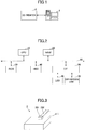
- FIG. 1 is a diagram illustrating an operating configuration of the solid object modeling system according to the present embodiment.
- the solid object modeling system according to the present embodiment includes a PC 1 and a 3D printer 2.
- the PC 1 generates modeling data by analyzing and converting entered 3D data, and outputs the modeling data to the 3D printer 2.
- the 3D printer 2 is an example of a solid object modeling device, and performs solid object modeling in accordance with control of the PC 1. Accordingly, the 3D printer 2 is an example of a manufacturing device of a 3D model.
- a hardware configuration of the PC 1 will be described with reference to FIG. 2 .
- the PC 1 according to the present embodiment includes a hardware configuration similar to a general purpose information processing device. That is, the PC 1 according to the present embodiment includes a CPU (Central Processing Unit) 10, a RAM (Random Access Memory) 20, a ROM (Read-Only Memory) 30, an HDD (Hard Disk Drive) 40, and an I/F (Interface) 50, each of which is interconnected via a bus 80. Also, an LCD (Liquid Crystal Display) 60 and an operation unit 70 are connected to the I/F 50.
- a CPU Central Processing Unit
- RAM Random Access Memory
- ROM Read-Only Memory
- HDD Hard Disk Drive
- I/F Interface
- a software control unit is configured. Functions of the PC 1 according to the present embodiment are embodied by a combination of the configured software control unit and the hardware.
- the 3D printer 2 includes a flat base 211 on which a filament is layered, a discharging head 201 for discharging a filament on the base 211, and an arm 202 for moving the discharging head 201 in a space above the base 211.
- the 3D printer 2 discharges a filament from the discharging head 201 to form each layer of a solid object to be formed, in accordance with a sliced image of each layer generated by horizontally slicing a three-dimensional shape of the solid object determined by entered modeling data, and deposits each layer sequentially to form the solid object.
- a filament is discharged from the discharging head 201 to a position corresponding to image data of the sliced image.
- a part where a filament is discharged becomes a shape corresponding to image data of the sliced image. That is, the discharging head 201 and the arm 202 acts as a filament discharging unit for selectively discharging a filament to a position determined based on information of a three-dimensional shape of a 3D model to be formed.
- a new filament layer is formed on a layer which has already been formed.
- a solid object is formed. That is, the base 211 acts as a stage when a filament is discharged.
- a hardware configuration of the 3D printer 2 is also similar to the hardware configuration of the PC 1 described with reference to FIG. 2 .
- the 3D printer 2 receives a control from the PC 1 by an information processing function embodied by the hardware configuration. Also, by a controller 220 (to be described below) embodied by the information processing function, movement of the arm 202 or discharge of a filament from the discharging head 201 is controlled.
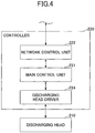
- the 3D printer 2 according to the present embodiment includes not only the discharging head 201 but also the controller 220 for controlling the discharging head 201.
- the controller 220 includes a main control unit 221, a network control unit 222, and a discharging head driver 224.
- the main control unit 221 has a function to control the controller 220 in entirety, and is embodied by the CPU in the 3D printer 2 performing arithmetic operations in accordance with an OS or an application program.
- the network control unit 222 is an interface of the 3D printer 2 to exchange information with other equipment such as the PC 1, and an Ethernet (registered trademark) interface or a USB (Universal Serial Bus) interface is used as the network control unit 222.
- the discharging head driver 224 is driver software for driving the discharging head 201.
- the discharging head driver 224 performs driving of the discharging head 201 by a control of the main control unit 221.
- the 3D data conversion processing unit 120 analyzes the obtained 3D data, and creates modeling data such as toolpath by converting the 3D data.
- the 3D data conversion processing unit 120 according to the present embodiment creates modeling data such that, when a 3D model having a three-dimensional shape represented by the input 3D data is formed on the base 211, a gap region formed between filaments becomes small or a gap region is not created. That is, the PC 1 including the 3D data conversion processing unit 120 is an example of an information processing device. Details will be described below.
- the 3D printer driver 130 is a software module for controlling an operation of the 3D printer 2 by the PC 1, and may have functions similar to general purpose driver software for a 3D printer.
- a function embodied by the 3D printer driver 130 is based on a function implemented in a printer driver of a generic printer for paper.
- the 3D printer driver 130 generates data (hereinafter referred to as "slice data") of the cross-sectional shape of each layer of a 3D model formed by cutting a three-dimensional shape of the 3D model represented by 3D data into slices, and sends the slice data to the 3D printer 2 with control information.
- information representing a route A of the toolpath which is a set of coordinates data for drawing a trajectory
- information indicating a width B of the toolpath which is a width of a filament discharged from the discharging head 201 of the 3D printer 2
- information indicating other setting values for forming a 3D model by the 3D printer 2 The information representing the route A of the toolpath also includes a predetermined constant bending angle (to be described below) for bending a driving direction of the toolpath.
- the 3D data conversion processing unit 120 generates gap suppression control data based on toolpath data.
- the gap suppression control data can make the gap regions E1, E2, etc. between filaments F small, or can eliminate the gap regions. Accordingly, forming a 3D model can be performed more precisely.
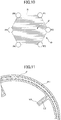
- the gap region data acquisition unit 124 also attaches a path label to a pixel positioned in a toolpath region J, which represents a region in the internal region C where the toolpath is drawn, and attaches a gap label to a pixel positioned in a gap region K, which represents a region in the internal region C where the toolpath is not drawn, as illustrated in FIG. 14C .
- the gap region data acquisition unit 124 classifies the internal region C into the toolpath region J and the gap region K (step S1205).
- a pixel to which a gap label is attached here is a gap pixel.
- the gap region data acquisition unit 124 attaches a check label to each of the gap pixels located in the gap region corresponding to the gap region data saved at step S1211 (step S1212).
- the gap region data acquisition unit 124 determines if all gap pixels in the image acquired at step S1206 have been searched for (step S1213). If not all gap pixels have been searched for (step S1213/NO), the process of the gap region data acquisition unit 124 reverts to step S1207, and the gap region data acquisition unit 124 repeats steps from step S1207 to step S1212.
- the gap region data acquisition unit 124 regards a pixel having a check label attached as a processed pixel, and excludes the pixel from a processing target of the steps. After all gap pixels has been searched for (step S1213/YES), the process of the gap region data acquisition unit 124 proceeds to step S1214.
- FIG. 16 is a flowchart illustrating an operation of the gap region data acquisition unit 124 and the data processing unit 125 according to the present embodiment.
- a same number as a number attached to that in the first embodiment is attached, and the description of the process may be omitted.
- step S1702 the process proceeds to step S1702, and, with respect to all parts Q of the toolpaths L extracted at step S1701, the data processing unit 125 adjusts width of the toolpaths L in accordance with the procedure mentioned above with reference to FIGS. 15A to 15D , by extracting a perpendicular direction element N that is perpendicular to a driving direction M of the toolpaths L, calculating a width P of the gap region K in a direction of the perpendicular direction element N, and determining the width B after adjustment of the toolpaths L based on the calculated width P (step S1702).
- the data processing unit 125 obtains data concerning the adjustment of the toolpath width performed at step S1701, as the gap suppression control data, and adds the obtained gap suppression control data to the toolpath data, to generate modeling data which is discharging information for controlling discharge of a filament.
- FIG. 19 is a flowchart illustrating an operation of the gap region data acquisition unit 124 and the data processing unit 125 according to the present embodiment.
- a same number as a number attached to that in the first embodiment is attached, and the description of the process may be omitted.
- the data processing unit 125 obtains data concerning the adjustment of the toolpath width performed at step S1214, as the gap suppression control data, and adds the obtained gap suppression control data to the toolpath data, to generate modeling data which is discharging information for controlling discharge of a filament.
- a case as illustrated in FIG. 20A is an example of a case in which a 3D model is double y-shaped, has a narrow part, and a gap region is formed in the narrow part.
- the data processing unit 125 changes a route A of all toolpaths to reduce a size of the gap region K corresponding to the gap region data saved at step S1211, or preferably to eliminate the gap region K (step S2101). That is, at step S2101, the data processing unit 125 enlarges bending angles of the route A of all the toolpaths L, for example, a bending angle ⁇ 1 of 45 degrees is changed to a bending angle ⁇ 2 of 60 degrees, as illustrated in FIGS. 22A and 22B . Each of these bending angles ⁇ 1 and ⁇ 2 is a value used for generating toolpath data, and is a predetermined value.
- a ratio of gap pixels to the number of all pixels in the search region T extracts all search regions T whose calculated ratio of gap pixels is not less than a predetermined threshold and which are adjacent to another search region T of which the calculated ratio of gap pixels is not less than the predetermined threshold (step S2302).
- An example will be described in the following.
- Six search regions T illustrated in FIG. 24D correspond to six search regions T illustrated on the upper side of FIG. 24C .
- four search regions T excluding search regions at both ends are search regions having a ratio of gap pixels to the number of all pixels in one search region T larger than the predetermined threshold.
- the gap region data acquisition unit 124 recognizes all of the connected search regions T to be a single gap region K, and saves information about size and location of the recognized gap region K as gap region data (step S2305). Subsequently, the process proceeds to step S2306, and the gap region data acquisition unit 124 attaches a check label to each of the pixels located in the gap region K corresponding to the gap region data saved at step S2305. Next, the process proceeds to step S2307, and the gap region data acquisition unit 124 determines if a search of gap pixels on a per search region basis T (performed at step S2301) is completed in an entirety of an image.
- a gap region K between toolpaths L running along an outline R in the present embodiment means a gap region that is directly generated by toolpaths L running along an outline R, and a gap region that is generated only indirectly by toolpaths L running along an outline R is not included in a scope of a gap region K between toolpaths L running along an outline R in the present embodiment. Therefore, a gap region K between toolpaths L running along an outline R in the present embodiment does not include a gap region K generated by only toolpaths L not running along an outline R. The same rule is applied to each of the following embodiments to be described below.
- step S3001 if at least one gap region K between toolpaths L running along an outline R is included among all gap regions K corresponding to the gap region data (step S3001/YES), the process proceeds to step S3002 and the data processing unit 125 adjusts widths B and routes A of all toolpaths L.
- the data processing unit 125 obtains data concerning the adjustment of the widths B and routes A of all the toolpaths L performed at step S3002, as the gap suppression control data, and adds the obtained gap suppression control data to the toolpath data, to generate modeling data which is discharging information for controlling discharge of a filament.
- step S3001/NO if a gap region K between toolpaths L running along an outline R is not included in all the gap regions K corresponding to gap region data (step S3001/NO), the process proceeds to step S1214, and a process similar to that described in the first embodiment will be carried out.
- widths B of all toolpaths L are expanded, and routes A of all the toolpaths L are moved toward an inside of an outline R of an internal region C represented by the contour information G.
- the width B and the route A of the toolpaths L after adjustment are determined such that a gap region E2 between toolpaths L running along an outline R can be reduced in size or preferably eliminated, and that the outline R can be maintained in the same condition as the outline R before adjustment.
- FIG. 27 is a flowchart illustrating an operation of the gap region data acquisition unit 124 and the data processing unit 125 according to the present embodiment.
- a same number as a number attached to that in the second embodiment is attached, and the description of the process may be omitted.
- a same number as a number attached to that in the seventh embodiment is attached, and the description of the process may be omitted.
- the data processing unit 125 determines, for every gap region K corresponding to every gap region data saved at step S1211, whether the gap region K is between toolpaths L running along an outline R, based on the contour information G acquired at step S1204 (step S3001). If at least one gap region K between toolpaths L running along an outline R is included among all gap regions K corresponding to gap region data (step S3001/YES), the process proceeds to step S3002 and the data processing unit 125 adjusts widths B and routes A of toolpaths L in a similar manner to the seventh embodiment. A process to be performed thereafter is similar to the process as described in the seventh embodiment.
- FIG. 29 is a flowchart illustrating an operation of the gap region data acquisition unit 124 and the data processing unit 125 according to the present embodiment.
- a same number as a number attached to that in the fifth embodiment is attached, and the description of the process may be omitted.
- a same number as a number attached to that in the seventh embodiment is attached, and the description of the process may be omitted.
- the solid object modeling system according to the sixth embodiment also reduces a size of a gap region K between toolpaths L, or preferably eliminates the gap region, by expanding a width of the toolpath L.
- a change of a route A of a toolpath L is performed in addition to an expansion of a width B of the toolpath L, which consequently mitigates an effect on an outline R of a 3D model by a process for expanding a width of the toolpath L in order to reduce a size of a gap region K between toolpaths L running along an outline R or preferably to eliminate the gap region K.
- step S3001/NO if a gap region K between toolpaths L running along an outline R is not included in all the gap regions K corresponding to gap region data (step S3001/NO), the process proceeds to step S1214, and a process similar to that described in the first embodiment will be carried out.
- the gap region E2 can be eliminated, and the toolpath L is prevented from extending outside of the outline R.
- quality of a surface of a 3D model can be improved, and forming of a 3D model by the 3D printer 2 can be performed more precisely.
- 3D data conversion processing unit 120 generates gap suppression control data.
- functions of the 3D data conversion processing unit 120 and the 3D printer driver 130 may be incorporated in the 3D printer 2.
- 3D data acquired by the 3D data acquisition unit 121 that was described with reference to FIGS. 7A to 7D may be entered to the 3D printer 2.
Landscapes
- Engineering & Computer Science (AREA)
- Chemical & Material Sciences (AREA)
- Materials Engineering (AREA)
- Manufacturing & Machinery (AREA)
- Physics & Mathematics (AREA)
- Theoretical Computer Science (AREA)
- Mechanical Engineering (AREA)
- Geometry (AREA)
- General Physics & Mathematics (AREA)
- Optics & Photonics (AREA)
- Computer Hardware Design (AREA)
- Evolutionary Computation (AREA)
- General Engineering & Computer Science (AREA)
- Automation & Control Theory (AREA)
- Software Systems (AREA)
- Computer Graphics (AREA)
- Human Computer Interaction (AREA)
Abstract
Description
- The present disclosure relates to an information processing device, a solid object modeling system, an information processing method, an information processing program, and a computer-readable recording medium, especially relates to a processing technique of solid object information (three-dimensional information) representing a three-dimensional shape of a solid object to be modeled by a solid object modeling device.
- In recent years, a technology called additive manufacturing is receiving attention. In the additive manufacturing, a solid object (which is a three-dimensional object, and hereinafter may be referred to as a "3D model") is modeled by depositing layers of molding materials using a solid object modeling device (what is called a 3D printer). The additive manufacturing is implemented by a 3D printer for discharging filamentary molding material (hereinafter may be referred to as "filament") to a designated location, and by a software for creating a 3D model from 3D model data designated by a user and for indicating to the 3D printer a location where the filament is to be discharged. The software analyzes the 3D model data, and converts the 3D model data into a control code for controlling the 3D printer, using a module called "slicer" included in the software.
- The slicer cuts the 3D model into slices having a same thickness along a Z-axis direction, and generates slice data from the cross-sectional shape of the 3D model at each Z coordinate. In the above mentioned additive manufacturing, based on the slice data, toolpath data, which represents a path and width of a toolpath indicating a location where the filament is to be discharged, is generated, and the toolpath data is processed from a piece of the toolpath data corresponding to the lowermost layer of the 3D model. The 3D model is created by depositing filament layers from the lowermost layer to the uppermost layer. Each filament layer is formed by discharging a filament from the 3D printer, with discharge location of the filament moved in accordance with the toolpath data of each layer. The toolpath data is trajectory information representing a path and width of the toolpath, and the toolpath indicates a location where the filament is to be discharged when an outline or an interior of the slice data is generated with a single stroke.
- In the additive manufacturing technique, a method for generating toolpath is proposed, in which a hatch path is determined based on intersections of the hatch and an outline, in generating a fill parameter (see
Patent Document 1, for example). - [Patent Document 1] Japanese Unexamined Patent Application Publication No.
2001-353786 - In the method disclosed in
Patent Document 1, toolpath data representing a path and width of the toolpath that indicates a location where the filament is to be discharged with a single stroke is generated, and a 3D model is created by depositing a filament based on the generated toolpath data. In creating the 3D model, if an amount of discharge of a filament per unit of time is constant, a gap, in which a filament is not filled, may occur on a surface of the 3D model or inside the 3D model. - The present disclosure is made to solve the above problem, and aims at, when creating a 3D model by depositing layers of molding materials by discharging filamentary molding materials on a flat surface, making a gap which may occur between the filamentary molding materials discharged on the flat surface small, or preferably eliminating the gap.
- To solve the above problem, according to one aspect of the present disclosure, there is provision of an information processing device for processing three-dimensional information representing a three-dimensional shape of a solid object to be modeled by a solid object modeling device configured to model the solid object by depositing a plurality of layers each of which is formed by discharging the filamentary molding material on the flat surface. The information processing device includes: a three-dimensional information acquisition unit configured to acquire the three-dimensional information; a layer information generating unit configured to generate a plurality of pieces of layer information corresponding to the respective layers of the filamentary molding materials, by slicing the three-dimensional information; a deposition information generating unit configured to generate, from the layer information, deposition information used for depositing the filamentary molding material by discharging the filamentary molding material on the flat surface; a gap region information generating unit configured to generate gap region information representing a gap region to be formed between the filamentary molding materials by depositing the filamentary molding material based on the deposition information; and a discharging information generating unit configured to generate discharging information for controlling discharge of the filamentary molding material, in accordance with the deposition information and the gap region information.
- According to the present disclosure, when creating a 3D model by depositing layers of molding materials by discharging filamentary molding materials on a flat surface, a gap which may occur between the filamentary molding materials discharged on the flat surface can be made small, or the gap can be preferably eliminated.
-
-
FIG. 1 is a diagram illustrating an operating configuration of a solid object modeling system according to a first embodiment; -
FIG. 2 is a diagram illustrating an example of a hardware configuration of an information processing device according to the first embodiment; -
FIG. 3 is a perspective view illustrating an example of a configuration of a 3D printer according to the first embodiment; -
FIG. 4 is a block diagram illustrating an example of a functional configuration of the 3D printer according to the first embodiment; -
FIG. 5 is a block diagram illustrating an example of a functional configuration of a PC (Personal Computer) according to the first embodiment; -
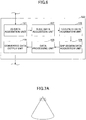
FIG. 6 is a block diagram illustrating an example of a functional configuration of a 3D data conversion processing unit according to the first embodiment; -
FIG. 7A is a diagram (1) illustrating an example of a 3D data conversion process according to the first embodiment; -
FIG. 7B is a diagram (2) illustrating the example of the 3D data conversion process according to the first embodiment; -
FIG. 7C is a diagram (3) illustrating the example of the 3D data conversion process according to the first embodiment; -
FIG. 7D is a diagram (4) illustrating the example of the 3D data conversion process according to the first embodiment; -
FIG. 8 is a diagram illustrating an example of toolpath data according to the first embodiment; -
FIG. 9 is a diagram illustrating an exemplary configuration of the toolpath data according to the first embodiment; -
FIG. 10 is a diagram illustrating an example of contour information in the toolpath data according to the first embodiment; -
FIG. 11 is a diagram illustrating an example of a gap region formed between filaments that may be formed when creating a 3D model with the 3D printer; -
FIG. 12 is a flowchart illustrating an operation of a gap region data acquisition unit and the data processing unit according to the first embodiment; -
FIG. 13A is a diagram (1) illustrating an example of a process for converting toolpath data into image data according to the first embodiment; -
FIG. 13B is a diagram (2) illustrating the example of the process for converting the toolpath data into the image data according to the first embodiment; -
FIG. 13C is a diagram (3) illustrating the example of the process for converting the toolpath data into the image data according to the first embodiment; -
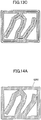
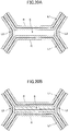
FIG. 14A is a diagram (1) illustrating an example of a process for separating a region where a toolpath is drawn and a region where a toolpath is not drawn according to the first embodiment; -
FIG. 14B is a diagram (2) illustrating the example of the process for separating the region where the toolpath is drawn and the region where the toolpath is not drawn according to the first embodiment; -
FIG. 14C is a diagram (3) illustrating the example of the process for separating the region where the toolpath is drawn and the region where the toolpath is not drawn according to the first embodiment; -
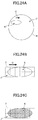
FIG. 15A is a diagram (1) illustrating an example of a process for expanding a width of a toolpath according to the first embodiment; -
FIG. 15B is a diagram (2) illustrating the example of the process for expanding the width of the toolpath according to the first embodiment; -
FIG. 15C is a diagram (3) illustrating the example of the process for expanding the width of the toolpath according to the first embodiment; -
FIG. 15D is a diagram (4) illustrating the example of the process for expanding the width of the toolpath according to the first embodiment; -
FIG. 16 is a flowchart illustrating an operation of a gap region data acquisition unit and a data processing unit according to a second embodiment; -
FIG. 17 is a flowchart illustrating an operation of a gap region data acquisition unit and a data processing unit according to a third embodiment; -
FIG. 18A is a diagram (1) illustrating an example of a process for extracting a part of a toolpath adjacent to a gap region according to the third embodiment; -
FIG. 18B is a diagram (2) illustrating the example of the process for extracting the part of the toolpath adjacent to the gap region according to the third embodiment; -
FIG. 19 is a flowchart illustrating an operation of a gap region data acquisition unit and a data processing unit according to a fourth embodiment; -
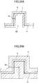
FIG. 20A is a diagram (1) illustrating an example of a process for adding a new toolpath in accordance with a size of a gap region according to the fourth embodiment; -
FIG. 20B is a diagram (2) illustrating the example of the process for adding the new toolpath in accordance with the size of the gap region according to the fourth embodiment; -
FIG. 21 is a flowchart illustrating an operation of a gap region data acquisition unit and a data processing unit according to a fifth embodiment; -
FIG. 22A is a diagram (1) illustrating an example of a process for adjusting a route of a toolpath according to the fifth embodiment; -
FIG. 22B is a diagram (2) illustrating the example of the process for adjusting the route of the toolpath according to the fifth embodiment; -
FIG. 23 is a flowchart illustrating an operation of a gap region data acquisition unit and a data processing unit according to a sixth embodiment; -
FIG. 24A is a diagram (1) illustrating an example of a process for searching for a gap region in each search region according to the sixth embodiment; -
FIG. 24B is a diagram (2) illustrating the example of the process for searching for the gap region in each search region according to the sixth embodiment; -
FIG. 24C is a diagram (3) illustrating the example of the process for searching for the gap region in each search region according to the sixth embodiment; -
FIG. 24D is a diagram (4) illustrating the example of the process for searching for the gap region in each search region according to the sixth embodiment; -
FIG. 25 is a flowchart illustrating an operation of a gap region data acquisition unit and a data processing unit according to a seventh embodiment; -
FIG. 26A is a diagram (1) illustrating an example of a process for processing a gap region between outlines according to the seventh embodiment; -
FIG. 26B is a diagram (2) illustrating the example of the process for processing the gap region between the outlines according to the seventh embodiment; -
FIG. 26C is a diagram (3) illustrating the example of the process for processing the gap region between the outlines according to the seventh embodiment; -
FIG. 27 is a flowchart illustrating an operation of a gap region data acquisition unit and a data processing unit according to an eighth embodiment; -
FIG. 28 is a flowchart illustrating an operation of a gap region data acquisition unit and a data processing unit according to a ninth embodiment; -
FIG. 29 is a flowchart illustrating an operation of a gap region data acquisition unit and a data processing unit according to a tenth embodiment; and -
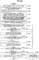
FIG. 30 is a flowchart illustrating an operation of a gap region data acquisition unit and a data processing unit according to an eleventh embodiment. - In the following, a first embodiment of the present disclosure will be described with reference to the drawings. In the description of the present embodiment, an example of a solid object modeling system including a 3D printer and a PC will be explained. The 3D printer in the solid object modeling system is configured to receive modeling data such as toolpath data, obtained by converting 3D data such as CAD (Computer Aided Design) data representing a shape of a 3D model, and to create the 3D model by depositing layers of filaments based on the modeling data. The PC is configured to send the modeling data to the 3D printer. In the following, the solid object modeling system according to the present embodiment, especially a data processing function of the PC performed when the modeling data is sent to the 3D printer, will be described.
-
FIG. 1 is a diagram illustrating an operating configuration of the solid object modeling system according to the present embodiment. The solid object modeling system according to the present embodiment includes aPC 1 and a3D printer 2. ThePC 1 generates modeling data by analyzing and converting entered 3D data, and outputs the modeling data to the3D printer 2. The3D printer 2 is an example of a solid object modeling device, and performs solid object modeling in accordance with control of thePC 1. Accordingly, the3D printer 2 is an example of a manufacturing device of a 3D model. A hardware configuration of thePC 1 will be described with reference toFIG. 2 . - As illustrated in
FIG. 2 , thePC 1 according to the present embodiment includes a hardware configuration similar to a general purpose information processing device. That is, thePC 1 according to the present embodiment includes a CPU (Central Processing Unit) 10, a RAM (Random Access Memory) 20, a ROM (Read-Only Memory) 30, an HDD (Hard Disk Drive) 40, and an I/F (Interface) 50, each of which is interconnected via abus 80. Also, an LCD (Liquid Crystal Display) 60 and anoperation unit 70 are connected to the I/F 50. - The
CPU 10 controls an entirety of thePC 1. TheRAM 20 is a volatile storage medium capable of high-speed information acquisition or information storage, and is used as a work area when theCPU 10 performs information processing. TheROM 30 is a read-only nonvolatile storage medium, and is used for storing a program such as firmware. TheHDD 40 is a nonvolatile storage medium capable of reading or writing information, and is used for storing an OS (Operating System), various control programs, an application program, and the like. - The I/
F 50 is for connecting various hardware or network to thebus 80. TheLCD 60 is a visual user interface used for checking status of thePC 1 by a user. Theoperation unit 70 is a user interface for entering information to thePC 1 by the user, and an example of theoperation unit 70 includes a keyboard and a mouse. - As the
CPU 10 performs arithmetic operations in accordance with a program loaded into theRAM 20 from theROM 30, theHDD 40, or a recording medium such as an optical disc (not illustrated) under the above mentioned hardware configuration, a software control unit is configured. Functions of thePC 1 according to the present embodiment are embodied by a combination of the configured software control unit and the hardware. - Next, a structure of the
3D printer 2 will be described with reference toFIG. 3 . The3D printer 2 according to the present embodiment includes aflat base 211 on which a filament is layered, a discharginghead 201 for discharging a filament on thebase 211, and anarm 202 for moving the discharginghead 201 in a space above thebase 211. - As mentioned earlier, the
3D printer 2 discharges a filament from the discharginghead 201 to form each layer of a solid object to be formed, in accordance with a sliced image of each layer generated by horizontally slicing a three-dimensional shape of the solid object determined by entered modeling data, and deposits each layer sequentially to form the solid object. Specifically, a filament is discharged from the discharginghead 201 to a position corresponding to image data of the sliced image. As a result, a part where a filament is discharged becomes a shape corresponding to image data of the sliced image. That is, the discharginghead 201 and thearm 202 acts as a filament discharging unit for selectively discharging a filament to a position determined based on information of a three-dimensional shape of a 3D model to be formed. - When forming of one layer is completed, a new filament layer is formed on a layer which has already been formed. By repeating the operation to deposit layers formed by discharging a filament sequentially, a solid object is formed. That is, the base 211 acts as a stage when a filament is discharged.
- Note that a hardware configuration of the
3D printer 2 is also similar to the hardware configuration of thePC 1 described with reference toFIG. 2 . The3D printer 2 receives a control from thePC 1 by an information processing function embodied by the hardware configuration. Also, by a controller 220 (to be described below) embodied by the information processing function, movement of thearm 202 or discharge of a filament from the discharginghead 201 is controlled. - Next, with reference to
FIG. 4 , an example of configuration of control blocks of the3D printer 2 according to the present embodiment will be described. As illustrated inFIG. 4 , the3D printer 2 according to the present embodiment includes not only the discharginghead 201 but also thecontroller 220 for controlling the discharginghead 201. - The
controller 220 includes amain control unit 221, anetwork control unit 222, and a discharginghead driver 224. Themain control unit 221 has a function to control thecontroller 220 in entirety, and is embodied by the CPU in the3D printer 2 performing arithmetic operations in accordance with an OS or an application program. Thenetwork control unit 222 is an interface of the3D printer 2 to exchange information with other equipment such as thePC 1, and an Ethernet (registered trademark) interface or a USB (Universal Serial Bus) interface is used as thenetwork control unit 222. The discharginghead driver 224 is driver software for driving the discharginghead 201. The discharginghead driver 224 performs driving of the discharginghead 201 by a control of themain control unit 221. - Next, with reference to
FIG. 5 , an example of configuration of function blocks of thePC 1 according to the present embodiment will be described. As illustrated inFIG. 5 , thePC 1 according to the present embodiment includes acontroller 100 and a network I/F 101, in addition to theLCD 60 and theoperation unit 70 described with reference toFIG. 2 . The network I/F 101 is an interface for communicating thePC 1 with other equipment via a network, and an Ethernet (registered trademark) interface or a USB (Universal Serial Bus) interface is used as the network I/F 101. - The
controller 100 is embodied by theCPU 10 performing arithmetic operations in accordance with an OS or an application program, and acts as a control unit for controlling thePC 1 in entirety. As illustrated inFIG. 5 , thecontroller 100 includes a3D data application 110, a 3D dataconversion processing unit 120, and a3D printer driver 130. - The
3D data application 110 is application software such as CAD software, to process data expressing a 3-dimensional shape of an object. The 3D dataconversion processing unit 120 is a 3D information processing unit performing a process for converting entered 3D data. That is, a program embodying the 3D dataconversion processing unit 120 is an example of an information processing program. - An input of 3D data to the 3D data
conversion processing unit 120 is performed by the 3D dataconversion processing unit 120 obtaining data entered into thePC 1 via a network, or by the3D data application 110 calling a function of the 3D dataconversion processing unit 120. Alternatively, the input may be performed by the 3D dataconversion processing unit 120 obtaining file path data specified by a user operating theoperation unit 70. - The 3D data
conversion processing unit 120 analyzes the obtained 3D data, and creates modeling data such as toolpath by converting the 3D data. The 3D dataconversion processing unit 120 according to the present embodiment creates modeling data such that, when a 3D model having a three-dimensional shape represented by theinput 3D data is formed on thebase 211, a gap region formed between filaments becomes small or a gap region is not created. That is, thePC 1 including the 3D dataconversion processing unit 120 is an example of an information processing device. Details will be described below. - The
3D printer driver 130 is a software module for controlling an operation of the3D printer 2 by thePC 1, and may have functions similar to general purpose driver software for a 3D printer. A function embodied by the3D printer driver 130 is based on a function implemented in a printer driver of a generic printer for paper. The3D printer driver 130 generates data (hereinafter referred to as "slice data") of the cross-sectional shape of each layer of a 3D model formed by cutting a three-dimensional shape of the 3D model represented by 3D data into slices, and sends the slice data to the3D printer 2 with control information. - Next, functions of the 3D data
conversion processing unit 120 will be described with reference toFIG. 6 . As illustrated inFIG. 6 , the 3D dataconversion processing unit 120 according to the present embodiment includes a 3Ddata acquisition unit 121, a slicedata acquisition unit 122, a toolpathdata acquisition unit 123, a gap regiondata acquisition unit 124, adata processing unit 125, and a converteddata output unit 126. - The 3D
data acquisition unit 121 generates and acquires 3D data of a 3D model, as illustrated inFIG. 7A for example, which is entered into the 3D dataconversion processing unit 120. That is, the 3Ddata acquisition unit 121 is an example of a three-dimensional information acquisition unit. As mentioned earlier, 3D data is information representing a three-dimensional shape of a 3D model to be formed. The slicedata acquisition unit 122 analyzes the 3D data acquired by the 3Ddata acquisition unit 121, slices the 3D data by a constant pitch, such as a pitch equal to a thickness of a filament discharged on thebase 211, in a Z-axis direction or a vertical direction, generates data of cross-sectional shape of the 3D data at each Z coordinate that is obtained by the slicing, such as slice data of each layer as illustrated inFIG. 7B , and acquires the data. That is, the slice data is an example of layer information, and the slicedata acquisition unit 122 is an example of a layer information generating unit. - The toolpath
data acquisition unit 123 is an example of a deposition information generating unit, and for each of the layers represented by the slice data acquired by the slicedata acquisition unit 122, the toolpathdata acquisition unit 123 generates, from slice data of a layer as illustrated inFIG. 7C for example, data of a trajectory (hereinafter referred to as "toolpath data") for drawing an outline of the slice data and an interior of the slice data with at least a single stroke, as illustrated inFIG. 7D for example. The toolpathdata acquisition unit 123 performs generating toolpath data for each layer. The toolpath data is an example of deposition information. The toolpath data includes, as illustrated inFIG. 8 , information representing a route A of the toolpath, which is a set of coordinates data for drawing a trajectory, information indicating a width B of the toolpath, which is a width of a filament discharged from the discharginghead 201 of the3D printer 2, and information indicating other setting values for forming a 3D model by the3D printer 2. The information representing the route A of the toolpath also includes a predetermined constant bending angle (to be described below) for bending a driving direction of the toolpath. - The information representing the route A of the toolpath contained in the toolpath data includes, as illustrated in
FIG. 9 for example, a route of the toolpath (X, Y, and Z coordinates). When a 3D model is formed by the3D printer 2, the discharginghead 201 of the3D printer 2 is driven in accordance with the coordinates of each row. The information indicating the width B of the toolpath includes, for example, two values of speeds: a moving speed of the discharginghead 201 and a discharging speed of a filament. In this case, the width B of the toolpath is determined by the two values of speeds. The toolpath data also includes contour information G representing an outline R. The contour information G is a set of coordinates data separating an internal region C of a 3D model (where a filament is discharged) and an external region D (where a filament is not discharged). For example, the contour information G is a set of vertex coordinates as illustrated inFIG. 10 (P0, P1,..., P5). - The gap region
data acquisition unit 124 converts toolpath data into image data, detects a gap pixel by classifying the image data, detects a gap region based on the detected gap pixel, generates gap region data representing the detected gap region, and obtains the gap region data. That is, the gap regiondata acquisition unit 124 is an example of a gap region information generating unit. - Based on the toolpath data acquired by the toolpath
data acquisition unit 123 and the gap region data acquired by the gap regiondata acquisition unit 124, thedata processing unit 125 generates gap suppression control data for reducing a size of a gap region which may occur between filaments when creating a 3D model with the3D printer 2, or preferably for eliminating the gap region. The gap suppression control data is data for performing control of enlarging a thickness or width of a filament to be discharged on thebase 211, by, for example, reducing a moving speed of the discharginghead 201, increasing a discharging speed of a filament discharged from the discharginghead 201, or the like. Thedata processing unit 125 also generates discharging information (that is, modeling data) for controlling discharge of a filament, by adding the gap suppression control data to the toolpath data. That is, thedata processing unit 125 is an example of a discharging information generating unit. - The converted
data output unit 126 outputs, to the3D printer driver 130, the modeling data generated by thedata processing unit 125 by adding the gap suppression control data to the toolpath data. That is, the converteddata output unit 126 is an example of a 3D information output unit. The3D printer driver 130 creates a job for operating the3D printer 2 based on the modeling data, and sends data representing the job to the3D printer 2. - As described above, the 3D data
conversion processing unit 120 according to the present embodiment generates gap suppression control data based on toolpath data. In a case in which gap regions E1, E2, and the like are expected to be formed between filaments F as illustrated inFIG. 11 when creating a 3D model with the3D printer 2, the gap suppression control data can make the gap regions E1, E2, etc. between filaments F small, or can eliminate the gap regions. Accordingly, forming a 3D model can be performed more precisely. - Next, an operation of a system according to the present embodiment will be described.
FIG. 12 is a flowchart illustrating an operation of the gap regiondata acquisition unit 124 and thedata processing unit 125 according to the present embodiment. As illustrated inFIG. 12 , first, toolpath data corresponding to one layer is entered to the gap region data acquisition unit 124 (step S1201). The gap regiondata acquisition unit 124 converts coordinates data included in the toolpath data, which is an X value and a Y value of coordinates as illustrated inFIG. 13A , into pixel data on an image (step S1202). In this case, a size of the image is set such that the3D printer 2 can form. Subsequently, the gap regiondata acquisition unit 124 obtains image data for each layer, by generating route data having a predetermined width B of the toolpath as illustrated inFIG. 13C by connecting these pixel data (step S1203). - Next, the gap region
data acquisition unit 124 detects a gap pixel by classifying the image data generated at step S1203. For example, as illustrated inFIG. 14A , the gap regiondata acquisition unit 124 acquires contour information G representing an outline R of the entire toolpath illustrated inFIG. 14A . Subsequently, based on the acquired contour information G, the gap regiondata acquisition unit 124 classifies the image data generated at step S1203 into an internal region C and an external region D illustrated inFIG. 14B , attaches an inside label to a pixel positioned in the internal region C, and attaches an outside label to a pixel positioned in the external region D (step S1204). The gap regiondata acquisition unit 124 also attaches a path label to a pixel positioned in a toolpath region J, which represents a region in the internal region C where the toolpath is drawn, and attaches a gap label to a pixel positioned in a gap region K, which represents a region in the internal region C where the toolpath is not drawn, as illustrated inFIG. 14C . By performing the above operations, the gap regiondata acquisition unit 124 classifies the internal region C into the toolpath region J and the gap region K (step S1205). A pixel to which a gap label is attached here is a gap pixel. - Afterward, the gap region
data acquisition unit 124 detects image data related to the gap region K from image data of the gap pixels included in the gap region K detected at step S1205. That is, the gap regiondata acquisition unit 124 generates and acquires an image including only the toolpath region J and the gap region K separated from the image data obtained at step S1203 (step S1206). Next, the gap regiondata acquisition unit 124 searches the image (step S1207), and out of the gap pixels having gap labels, the gap regiondata acquisition unit 124 extracts all pixels adjacent to another gap pixel (step S1208). As a result of the search, if an adjacent gap pixel is not found (step S1208/NO), a process of the gap regiondata acquisition unit 124 proceeds to step S1213 to be described below. On the other hand, if all adjacent gap pixels are found (step S1208/YES) as a result of the search, the gap regiondata acquisition unit 124 connects the gap pixel with the adjacent gap pixel(s) (step S1209). - Next, the gap region
data acquisition unit 124 determines if all adjacent gap pixels are connected or not (step S1210). If not all adjacent gap pixels are connected (step S1210/NO), the process of the gap regiondata acquisition unit 124 reverts to step S1209, and the gap regiondata acquisition unit 124 repeats a process to connect the extracted gap pixel to adjacent gap pixel. On the other hand, if all adjacent gap pixels are connected (step S1210/YES), the gap regiondata acquisition unit 124 determines a region covered with all of the connected gap pixels as a single gap region, and saves size information of the determined gap region and location information of the determined gap region, as gap region data (step S1211). The gap region data mentioned here is an example of gap region information. - Next, the gap region
data acquisition unit 124 attaches a check label to each of the gap pixels located in the gap region corresponding to the gap region data saved at step S1211 (step S1212). Next, the gap regiondata acquisition unit 124 determines if all gap pixels in the image acquired at step S1206 have been searched for (step S1213). If not all gap pixels have been searched for (step S1213/NO), the process of the gap regiondata acquisition unit 124 reverts to step S1207, and the gap regiondata acquisition unit 124 repeats steps from step S1207 to step S1212. When repeating the steps, the gap regiondata acquisition unit 124 regards a pixel having a check label attached as a processed pixel, and excludes the pixel from a processing target of the steps. After all gap pixels has been searched for (step S1213/YES), the process of the gap regiondata acquisition unit 124 proceeds to step S1214. - At step S1214, the
data processing unit 125 reduces a size of the gap region K corresponding to the gap region data saved at step S1211, or preferably eliminates the gap region K, by expanding width of all toolpaths (step S1214). Thedata processing unit 125 at step S1214 adjusts width of all the toolpaths to expand the width of all the toolpaths, based on a size (width P to be described below) of each gap region. In a case in which multiple gap regions are present, thedata processing unit 125 determines a width B after adjustment (to be described later) of the toolpaths based on a size (width P) of the largest (having a maximum width P) gap region among the multiple gap regions. During the adjustment, thedata processing unit 125 extracts a perpendicular direction element N that is perpendicular to a driving direction M of toolpath L adjacent to a gap region K, as illustrated inFIG. 15A and FIG. 15B , and calculate a width P, which is a length (width) of the gap region K in a direction of the perpendicular direction element N (seeFIG. 15C ). Next, based on the calculated width P, the width B after adjustment of all the toolpaths L is determined. - Next, the
data processing unit 125 obtains data concerning the adjustment of the toolpath width performed at step S1214, as the gap suppression control data, and adds the obtained gap suppression control data to the toolpath data, to generate modeling data which is discharging information for controlling discharge of a filament. - And then, when a user instructs, by operating the
operation unit 70, to start forming a solid object by the3D printer 2, the converteddata output unit 126 outputs the modeling data generated by thedata processing unit 125. The3D printer driver 130 having received the modeling data generates data of a job for causing the3D printer 2 to perform forming a solid object, and transmits the data to cause the3D printer 2 to perform forming a solid object. By performing the above process, the entire operation of the system according to the present embodiment is completed. - Next, an operation of the
3D printer 2 having received data of a job will be described. Themain control unit 221 in thecontroller 220 controls the discharginghead driver 224 based on the data of the job, and moves the discharginghead 201 to a predetermined position above the base 211 using thearm 202. After driving the discharginghead 201, themain control unit 221 refers to the modeling data, and causes the discharginghead 201 to discharge a filament on the base 211 while driving the discharginghead 201 using thearm 202 based on the toolpath data of the lowest layer. After completing discharge of a filament corresponding to one layer, themain control unit 221 repeats the discharge operation of a filament until the discharge for every layer is completed. By performing the above process, the operation of the3D printer 2 having received data of a job is completed. - As described above, the solid object modeling system according to the present embodiment determines a gap region that may occur between filaments when a 3D model is formed by discharging a filament based on toolpath data, and generates gap suppression control data for reducing a size of the gap region, or preferably eliminating the gap region, by increasing a width of toolpath. As a result, it is possible to control the
3D printer 2 to reduce a size of a gap between filaments or eliminate the gap, when it is predicted that a gap region is generated between filaments. Accordingly, because an occurrence of deformation, caused by a gap region occurring between filaments of a 3D model formed by the 3D printer, can be reduced, forming of a 3D model by the 3D printer can be performed more precisely. - The solid object modeling system according to the first embodiment reduces sizes of, or preferably eliminates, all gap regions detected based on gap pixels. The solid object modeling system according to a second embodiment differs from that of the first embodiment in that the solid object modeling system according to a second embodiment is configured such that a user sets a threshold of an area of a gap region to be processed in advance by inputting the threshold using the
operation unit 70 of thePC 1, and in that the solid object modeling system according to the second embodiment reduces a size of detected gap region, or preferably eliminates the detected gap region, only when the detected gap region has a larger area than the threshold. -
FIG. 16 is a flowchart illustrating an operation of the gap regiondata acquisition unit 124 and thedata processing unit 125 according to the present embodiment. In the following description, regarding a process similar to that in the first embodiment, a same number as a number attached to that in the first embodiment is attached, and the description of the process may be omitted. - In the present embodiment, as illustrated in
FIG. 16 , when all adjacent gap pixels are connected (step S1210/YES), the gap regiondata acquisition unit 124 determines if an area of a region covered with the connected gap pixels is equal to or larger than the predetermined threshold or not (step S1601). If the area of the region covered with the connected gap pixels is equal to or larger than the predetermined threshold (step S1601/YES), a process of the gap regiondata acquisition unit 124 proceeds to step 1211, in which the gap regiondata acquisition unit 124 determines the region covered with the connected gap pixels as a gap region, and saves size information of the determined gap region and location information of the determined gap region, as gap region data. The saved gap region data is gap region data corresponding to a gap region covered with the connected gap pixels having an area equal to or larger than the predetermined threshold, and is an example of threshold gap region information. Next, the process proceeds to step S1602, in which the gap regiondata acquisition unit 124 attaches a check label to each of the pixels located in the gap region corresponding to the gap region data saved at step S1211. After step S1602, the process proceeds to step S1213. If the area of the region covered with the connected gap pixels is smaller than the predetermined threshold (step S1601/NO), the process also proceeds to step S1602, in which the gap regiondata acquisition unit 124 attaches a check label to each of the connected gap pixels, and the process proceeds to step S1213. Processes to be performed at step S1213 and thereafter are similar to the processes described in the first embodiment. - As described above, the solid object modeling system according to the present embodiment determines a region made by connecting gap pixels as a gap region only when an area of the region is equal to or larger than the threshold, and reduces a size of the gap region, or preferably eliminates the gap region, by increasing a width of toolpath. Accordingly, because a process for a region made by connecting gap pixels having smaller area than the threshold can be omitted, the number of the gap regions to be processed can be lessened and a processing speed for forming modeling data can be improved.
- The solid object modeling system according to the first embodiment reduces sizes of gaps, or preferably eliminates gaps, by adjusting width of all toolpaths based on gap region data. In the solid object modeling system according to a third embodiment, instead of adjusting width of all toolpaths, a process of reducing a size of the gap region or preferably eliminating the gap region is performed with respect to a part of a toolpath adjacent to a gap region.
-
FIG. 17 is a flowchart illustrating an operation of the gap regiondata acquisition unit 124 and thedata processing unit 125 according to the present embodiment. In the following description, regarding a process similar to that in the first embodiment, a same number as a number attached to that in the first embodiment is attached, and the description of the process may be omitted. - As illustrated in
FIG. 17 , when the gap regiondata acquisition unit 124 completes searching for all gap pixels included in an entire image at step S1213, thedata processing unit 125 executes step S1701. At step S1701, thedata processing unit 125 acquires location information of gap regions corresponding to all gap region data saved at step S1211, and, as illustrated inFIG. 18A and FIG. 18B , thedata processing unit 125 extracts, out of toolpaths L, a part Q adjacent to each gap region K (step S1701). That is, at step S1701, as illustrated inFIG. 18A and FIG. 18B , thedata processing unit 125 extracts, out of all toolpaths L in the internal region, all parts Q of the toolpaths L adjacent to the gap region K. Information of these parts Q of the toolpaths L mentioned here is an example of discharge region information related to a part of filamentary molding material adjacent to a gap region. - Then, the process proceeds to step S1702, and, with respect to all parts Q of the toolpaths L extracted at step S1701, the
data processing unit 125 adjusts width of the toolpaths L in accordance with the procedure mentioned above with reference toFIGS. 15A to 15D , by extracting a perpendicular direction element N that is perpendicular to a driving direction M of the toolpaths L, calculating a width P of the gap region K in a direction of the perpendicular direction element N, and determining the width B after adjustment of the toolpaths L based on the calculated width P (step S1702). - Next, the
data processing unit 125 obtains data concerning the adjustment of the toolpath width performed at step S1701, as the gap suppression control data, and adds the obtained gap suppression control data to the toolpath data, to generate modeling data which is discharging information for controlling discharge of a filament. - As described above, the solid object modeling system according to the present embodiment extracts a part Q adjacent to a gap region K among toolpaths L, and with respect to the extracted part Q of the toolpaths L, a width of the toolpaths L is adjusted locally. Accordingly, a width of a part of the toolpath L that is not adjacent to the gap region is not adjusted. As a result, processing speed for forming modeling data can be improved. Further, because the width of the part of the toolpaths L other than the part Q adjacent to the gap region K is not adjusted, quality of a 3D model formed by the
3D printer 2 can be improved. - The solid object modeling system according to the first embodiment reduces a size of a gap region, or preferably eliminates a gap region, by adjusting a width of a toolpath based on a gap region related to gap region data. In the solid object modeling system according to a fourth embodiment, if there is a limitation of an increase in width of a toolpath to reduce a size of a gap region or preferably eliminate a gap region, or if a gap region cannot decrease in size or cannot preferably be eliminated, a new toolpath is added to the gap region to reduce a size of the gap region or preferably to eliminate the gap region.
-
FIG. 19 is a flowchart illustrating an operation of the gap regiondata acquisition unit 124 and thedata processing unit 125 according to the present embodiment. In the following description, regarding a process similar to that in the first embodiment, a same number as a number attached to that in the first embodiment is attached, and the description of the process may be omitted. - As illustrated in
FIG. 19 , after width of all toolpaths L has been adjusted at step S1214 to reduce sizes of gap regions K corresponding to all the gap region data or to preferably eliminate the gap regions K corresponding to all the gap region data, thedata processing unit 125 determines if part of a toolpath L2 (that is, a part of a region disclosed inFIG. 20A ) adjacent to a gap region K is also adjacent to a toolpath L1 running along an outline R, as illustrated inFIG. 20A (step S1901). If the part of the toolpath L2 adjacent to the gap region K is also adjacent to the toolpath L1 running along the outline R, as illustrated inFIG. 20A (step S1901/YES), thedata processing unit 125 restores a width of the part of the toolpath L2 to a width before adjustment (step S1902). Subsequently, as illustrated inFIG. 20B , thedata processing unit 125 adds a new toolpath S to the gap region K whose adjacent toolpath L2 is also adjacent to the toolpath L1 running along the outline R (step S1903). When the toolpath S is added, in accordance with a width of the gap region K to which the toolpath S is added, a width of the toolpath S may be expanded, or multiple toolpaths S may be added. - Next, the
data processing unit 125 obtains, as gap suppression control data, each of the data concerning the adjustment of the toolpath width performed at step S1214 and the data concerning the addition of the toolpath S performed at step S1903, and adds the obtained gap suppression control data to the toolpath data, to generate modeling data which is discharging information for controlling discharge of a filament. - Conversely, if part of the toolpath L2 adjacent to the gap region K is not adjacent to the toolpath L1 running along the outline R (step S1901/NO), the
data processing unit 125 obtains data concerning the adjustment of the toolpath width performed at step S1214, as the gap suppression control data, and adds the obtained gap suppression control data to the toolpath data, to generate modeling data which is discharging information for controlling discharge of a filament. - If a width of a toolpath L1 running along an outline R of modeling data were expanded, displacement of a toolpath from the outline R would occur when forming a 3D model, and unevenness might be formed on a surface of the formed 3D model. Therefore, there is a certain limitation in an adjustable range of a width of the toolpath L1. Further, even if a width of a toolpath L2 adjacent to the toolpath L1 running along the outline R were expanded in order to reduce a size of a gap region K between the toolpaths L2 or preferably to eliminate the gap region K, the size of the gap region K might not decrease, as illustrated in
FIG. 20A . - Note that a case as illustrated in
FIG. 20A is an example of a case in which a 3D model is double y-shaped, has a narrow part, and a gap region is formed in the narrow part. - In the solid object modeling system according to the present embodiment, the
data processing unit 125 determines if part of a toolpath L2 adjacent to a gap region K, whose width has been adjusted, is also adjacent to a toolpath L1 running along an outline R. If the part of the toolpath L2 adjacent to the gap region K is also adjacent to the toolpath L1 running along the outline R, a new toolpath S in accordance with a width of the gap region K is added to the gap region K to which the toolpath L2 is adjacent. Accordingly, in a case in which unevenness might be formed on a surface of the formed 3D model even if a width of a toolpath L1 were expanded, or in a case a gap region K might not be reduced in size or eliminated even if a width of a toolpath L2 were expanded, the solid object modeling system according to the present embodiment can reduce a size of the gap region K or can eliminate the gap region. As a result, quality of a surface of a 3D model can be improved, and forming of a 3D model by the3D printer 2 can be performed more precisely. - The solid object modeling system according to the first embodiment reduces a size of a gap region, or preferably eliminates a gap region, by adjusting a width of a toolpath. However, in the solid object modeling system according to a fifth embodiment, by changing a route of a toolpath, a size of the gap region is reduced or preferably the gap region is eliminated.
-
FIG. 21 is a flowchart illustrating an operation of the gap regiondata acquisition unit 124 and thedata processing unit 125 according to the present embodiment. In the following description, regarding a process similar to that in the first embodiment, a same number as a number attached to that in the first embodiment is attached, and the description of the process may be omitted. - As illustrated in
FIG. 21 , when the gap regiondata acquisition unit 124 completes searching for all gap pixels included in an entire image at step S1213, thedata processing unit 125 changes a route A of all toolpaths to reduce a size of the gap region K corresponding to the gap region data saved at step S1211, or preferably to eliminate the gap region K (step S2101). That is, at step S2101, thedata processing unit 125 enlarges bending angles of the route A of all the toolpaths L, for example, a bending angle Φ1 of 45 degrees is changed to a bending angle Φ2 of 60 degrees, as illustrated inFIGS. 22A and 22B . Each of these bending angles Φ1 and Φ2 is a value used for generating toolpath data, and is a predetermined value. - Next, the
data processing unit 125 obtains, as gap suppression control data, data concerning the adjustment of the bending angles of the toolpaths performed at step S2101, and adds the obtained gap suppression control data to the toolpath data, to generate modeling data which is discharging information for controlling discharge of a filament. - As described above, in forming toolpath data, a gap region K may be formed between toolpaths L depending on a bending angle Φ1 of the toolpath L as illustrated in
FIG. 22A . Therefore, in the present embodiment, by expanding a bending angle Φ1 of a route A of the toolpath L into a bending angle Φ2, the gap region K is reduced in size or preferably is eliminated. As a result, a size of a gap region E1, which may be formed between filaments F when a 3D model is formed by the 3D printer, can be reduced, or preferably the gap region can be eliminated. Accordingly, forming of a 3D model can be performed more precisely. - The solid object modeling system according to the first embodiment detects a gap region K by performing an extraction of a gap pixel in an image on a pixel-by-pixel basis. In a solid object modeling system according to the sixth embodiment, a search of a gap region K in an image is conducted by using a search region T having a predetermined fixed shape and area.
-
FIG. 23 is a flowchart illustrating an operation of the gap regiondata acquisition unit 124 and thedata processing unit 125 according to the present embodiment. In the following description, regarding a process similar to that in the first embodiment, a same number as a number attached to that in the first embodiment is attached, and the description of the process may be omitted. - As illustrated in
FIG. 23 , after the gap regiondata acquisition unit 124 acquires, at step S1206, an image including only the toolpath region J and the gap region K as illustrated inFIG. 24A , the gap regiondata acquisition unit 124 searches for a gap region K in the image, for each search region T having a predetermined shape and area (in a case illustrated inFIG 23B , a square corresponds to a search region T) (step S2301). Next, the gap regiondata acquisition unit 124 calculates, as illustrated inFIG. 24C andFIG. 24D , for each search region T, a ratio of gap pixels to the number of all pixels in the search region T, and extracts all search regions T whose calculated ratio of gap pixels is not less than a predetermined threshold and which are adjacent to another search region T of which the calculated ratio of gap pixels is not less than the predetermined threshold (step S2302). An example will be described in the following. Six search regions T illustrated inFIG. 24D correspond to six search regions T illustrated on the upper side ofFIG. 24C . Among the six search regions T illustrated inFIG. 24D , four search regions T excluding search regions at both ends are search regions having a ratio of gap pixels to the number of all pixels in one search region T larger than the predetermined threshold. If there is no adjacent search region T having a gap pixel ratio not less than the predetermined threshold (step S2302/NO), the process proceeds to step S2307, and the gap regiondata acquisition unit 124 determines whether the search is completed in every search region T included in the image acquired at step S1206. If the search has not been carried out in every search region T (step S2307/NO), the process reverts to step S2301, and the gap regiondata acquisition unit 124 conducts search of a gap region K with respect to a search region T adjacent, in a scanning direction U as illustrated inFIG. 24B , to the search region T in which the search has been carried out most recently, in a similar manner as described above. - If all adjacent search regions T having the gap pixel ratio not less than the predetermined threshold are extracted (step S2302/YES), the gap region
data acquisition unit 124 recognizes that an entirety of all the search regions T extracted at step S2302 is a part of the gap region K, and connects the search regions T with adjacent search regions T having the gap pixel ratio not less than the predetermined threshold (step S2303). - Next, at step S2304, the gap region
data acquisition unit 124 determines whether all adjacent search regions T having the gap pixel ratio not less than the predetermined threshold are connected (step S2304). If not all adjacent search regions T having the gap pixel ratio not less than the predetermined threshold have been connected (step S2304/NO), the process reverts to step S2303 and the gap regiondata acquisition unit 124 repeats a process for connecting a search region T having the gap pixel ratio not less than the predetermined threshold, with an adjacent search region T having the gap pixel ratio not less than the predetermined threshold. If all adjacent search regions T having the gap pixel ratio not less than the predetermined threshold have been connected (step S2304/YES), the gap regiondata acquisition unit 124 recognizes all of the connected search regions T to be a single gap region K, and saves information about size and location of the recognized gap region K as gap region data (step S2305). Subsequently, the process proceeds to step S2306, and the gap regiondata acquisition unit 124 attaches a check label to each of the pixels located in the gap region K corresponding to the gap region data saved at step S2305. Next, the process proceeds to step S2307, and the gap regiondata acquisition unit 124 determines if a search of gap pixels on a per search region basis T (performed at step S2301) is completed in an entirety of an image. - If a search of gap pixels on a per search region basis T has not been completed in an entirety of an image (step S2307/NO), the process reverts to step 2301, and the gap region
data acquisition unit 124 repeats the process of steps S2301 to S2306. With respect to repeating the process of steps S2301 to S2306, if the gap regiondata acquisition unit 124 finds a search region T including a pixel to which a check label is attached, the gap regiondata acquisition unit 124 determines that the process of steps S2301 to S2306 has already been completed with respect to the search region T, and the search region T is excluded from an object of the process of steps S2301 to S2306. When a search of gap pixels on a per search region basis T has been completed in an entirety of an image (step S2307/YES), the process proceeds to step 1214, and a process similar to that described in the first embodiment will be carried out. - As described above, the solid object modeling system according to the present embodiment scans an image for each search region T having a predetermined fixed shape and area, and determines if the search region T is a part of a gap region K or not. Further, adjacent search regions that are determined as the part of the gap region are regarded as a single gap region, and data relevant to the gap region is saved. Accordingly, since the solid object modeling system according to the present embodiment can simultaneously process all pixels in a search region T having a predetermined fixed shape and area, a processing speed for generating modeling data can be improved, as compared to the solid object modeling system according to the first embodiment, which searches for a gap region K by performing an extraction of a gap pixel for each pixel of an image.
- The solid object modeling system according to the first embodiment reduces a size of a gap region K between toolpaths L, or preferably eliminates the gap region, by expanding a width of the toolpath L. In the solid object modeling system according to a seventh embodiment, in a case in which a gap region K between toolpaths L runs along an outline R, a change of a route A of a toolpath L is performed in addition to an expansion of a width B of the toolpath L.
-
FIG. 25 is a flowchart illustrating an operation of the gap regiondata acquisition unit 124 and thedata processing unit 125 according to the present embodiment. In the following description, regarding a process similar to that in the first embodiment, a same number as a number attached to that in the first embodiment is attached, and the description of the process may be omitted. - As illustrated in
FIG. 25 , after the gap regiondata acquisition unit 124 completes searching for all gap pixels included in an entire image at step S1213, thedata processing unit 125 determines, for every gap region K corresponding to every gap region data saved at step S1211, whether the gap region K is between toolpaths L running along an outline R, based on the contour information G acquired at step S1204 (step S3001). An example of a gap region K between toolpaths L running along an outline R mentioned here is a gap region E2 between toolpaths L provided in a narrow space which is generated inside an outline R because of a local protrusion of the outline R, like the gap region E2 illustrated inFIG. 11 . Further, the gap region K illustrated inFIG. 20A , which is generated between the toolpaths L1 running along the outline R, is also an example of a gap region K between toolpaths L running along an outline R. As mentioned above, a gap region K between toolpaths L running along an outline R in the present embodiment means a gap region that is directly generated by toolpaths L running along an outline R, and a gap region that is generated only indirectly by toolpaths L running along an outline R is not included in a scope of a gap region K between toolpaths L running along an outline R in the present embodiment. Therefore, a gap region K between toolpaths L running along an outline R in the present embodiment does not include a gap region K generated by only toolpaths L not running along an outline R. The same rule is applied to each of the following embodiments to be described below. - At step S3001, if at least one gap region K between toolpaths L running along an outline R is included among all gap regions K corresponding to the gap region data (step S3001/YES), the process proceeds to step S3002 and the
data processing unit 125 adjusts widths B and routes A of all toolpaths L. Next, thedata processing unit 125 obtains data concerning the adjustment of the widths B and routes A of all the toolpaths L performed at step S3002, as the gap suppression control data, and adds the obtained gap suppression control data to the toolpath data, to generate modeling data which is discharging information for controlling discharge of a filament. - Conversely, if a gap region K between toolpaths L running along an outline R is not included in all the gap regions K corresponding to gap region data (step S3001/NO), the process proceeds to step S1214, and a process similar to that described in the first embodiment will be carried out.
- For example, in a case in which a gap region E2 exists between toolpaths L running along an outline R protruding upward as illustrated in
FIG. 26A , in order to eliminate the gap region E2, if a width of the toolpath L were expanded from W1 to W2 without changing a route A of the toolpath L as illustrated inFIG. 26B , the toolpath L would extend outside of the outline R. In the present embodiment, to prevent the toolpath L from extending outside of the outline R, in addition to expanding a width of the toolpath L from W1 to W3, a route A of the toolpath L is moved toward an inside of the outline R, as illustrated inFIG. 26C . As a result, the gap region E2 can be eliminated, and the toolpath L is prevented from extending outside of the outline R. As a result, according to the present embodiment, in addition to an effect of the above described first embodiment, quality of a surface of a 3D model can be improved, and forming of a 3D model by the3D printer 2 can be performed more precisely. - That is, in a process for adjusting widths B and routes A of all toolpaths L performed at step S3002, widths B of all toolpaths L are expanded, and routes A of all the toolpaths L are moved toward an inside of an outline R of an internal region C represented by the contour information G. The width B and the route A of the toolpaths L after adjustment are determined such that a gap region E2 between toolpaths L running along an outline R can be reduced in size or preferably eliminated, and that the outline R can be maintained in the same condition as the outline R before adjustment.
- The solid object modeling system according to the second embodiment expands a width of the toolpath L to reduce a size of a gap region K having an area not less than a threshold, or preferably to eliminate the gap region K. In the solid object modeling system according to an eighth embodiment, similar to the seventh embodiment, in a case in which a gap region K between toolpaths L runs along an outline R, a change of a route A of a toolpath L is performed in addition to an expansion of a width B of the toolpath L.
-
FIG. 27 is a flowchart illustrating an operation of the gap regiondata acquisition unit 124 and thedata processing unit 125 according to the present embodiment. In the following description, regarding a process similar to that in the second embodiment, a same number as a number attached to that in the second embodiment is attached, and the description of the process may be omitted. Further, regarding a process similar to that in the seventh embodiment, a same number as a number attached to that in the seventh embodiment is attached, and the description of the process may be omitted. - As illustrated in
FIG. 27 , similar to the seventh embodiment, when the gap regiondata acquisition unit 124 completes searching for all gap pixels included in an entire image at step S1213, thedata processing unit 125 determines, for every gap region K corresponding to every gap region data saved at step S1211, whether the gap region K is between toolpaths L running along an outline R, based on the contour information G acquired at step S1204 (step S3001). If at least one gap region K between toolpaths L running along an outline R is included among all gap regions K corresponding to gap region data (step S3001/YES), the process proceeds to step S3002 and thedata processing unit 125 adjusts widths B and routes A of toolpaths L in a similar manner to the seventh embodiment. A process to be performed thereafter is similar to the process as described in the seventh embodiment. - Conversely, if a gap region K between toolpaths L running along an outline R is not included in all the gap regions K corresponding to gap region data (step S3001/NO), the process proceeds to step S1214, and a process similar to that described in the first embodiment will be carried out.
- According to the present embodiment, in addition to an effect of the above described second embodiment, similar to the seventh embodiment, the gap region E2 can be eliminated, and the toolpath L is prevented from extending outside of the outline R. As a result, quality of a surface of a 3D model can be improved, and forming of a 3D model by the
3D printer 2 can be performed more precisely. - In the solid object modeling system according to the third embodiment, a width of a part of toolpaths L adjacent to a gap region K is expanded to reduce a size of a gap region K between the toolpaths L, or preferably to eliminate the gap region K. In the solid object modeling system according to a ninth embodiment, similar to the seventh embodiment, in a case in which a gap region K between toolpaths L runs along an outline R, a change of a route A of a part of a toolpath L adjacent to a gap region K is performed in addition to an expansion of a width of the part of the toolpath L.
-
FIG. 28 is a flowchart illustrating an operation of the gap regiondata acquisition unit 124 and thedata processing unit 125 according to the present embodiment. In the following description, regarding a process similar to that in the third embodiment, a same number as a number attached to that in the third embodiment is attached, and the description of the process may be omitted. Further, regarding a process similar to that in the seventh embodiment, a same number as a number attached to that in the seventh embodiment is attached, and the description of the process may be omitted. - As illustrated in
FIG. 28 , similar to the seventh embodiment, after the gap regiondata acquisition unit 124 completes searching for all gap pixels included in an entire image at step S1213, thedata processing unit 125 determines, for every gap region K corresponding to every gap region data saved at step S1211, whether the gap region K is between toolpaths L running along an outline R, based on the contour information G acquired at step S1204 (step S3001). If at least one gap region K between toolpaths L running along an outline R is included among all gap regions K corresponding to gap region data (step S3001/YES), the process proceeds to step S3012 and thedata processing unit 125 adjusts widths B and routes A of all the parts Q of the toolpaths L extracted at step S1701, in accordance with the procedure mentioned above with reference toFIGS. 26A to 26C . Next, thedata processing unit 125 obtains data concerning the adjustment of the widths B and routes A of all the parts Q of the toolpaths L performed at step S3012, as the gap suppression control data, and adds the obtained gap suppression control data to the toolpath data, to generate modeling data which is discharging information for controlling discharge of a filament. - Conversely, if a gap region K between toolpaths L running along an outline R is not included in all the gap regions K corresponding to gap region data (step S3001/NO), the process proceeds to step S1702, and a process similar to that described in the third embodiment will be carried out.
- According to the present embodiment, in addition to an effect of the above described third embodiment, similar to the seventh embodiment, the gap region E2 can be eliminated, and the toolpath L is prevented from extending outside of the outline R. As a result, quality of a surface of a 3D model can be improved, and forming of a 3D model by the
3D printer 2 can be performed more precisely. - In the solid object modeling system according to the fifth embodiment, by changing a route A of toolpaths L, a gap region K between the toolpaths L is reduced in size, or preferably is eliminated. In the solid object modeling system according to a tenth embodiment, similar to the seventh embodiment, in a case in which a gap region K between toolpaths L runs along an outline R, a change of a route A of a toolpath L is performed in addition to an expansion of a width B of the toolpath L.
-
FIG. 29 is a flowchart illustrating an operation of the gap regiondata acquisition unit 124 and thedata processing unit 125 according to the present embodiment. In the following description, regarding a process similar to that in the fifth embodiment, a same number as a number attached to that in the fifth embodiment is attached, and the description of the process may be omitted. Further, regarding a process similar to that in the seventh embodiment, a same number as a number attached to that in the seventh embodiment is attached, and the description of the process may be omitted. - As illustrated in
FIG. 29 , similar to the seventh embodiment, after the gap regiondata acquisition unit 124 completes searching for all gap pixels included in an entire image at step S1213, thedata processing unit 125 determines, for every gap region K corresponding to every gap region data saved at step S1211, whether the gap region K is between toolpaths L running along an outline R, based on the contour information G acquired at step S1204 (step S3001). If at least one gap region K between toolpaths L running along an outline R is included among all gap regions K corresponding to gap region data (step S3001/YES), the process proceeds to step S3002 and thedata processing unit 125 adjusts widths B and routes A of toolpaths L in a similar manner to the seventh embodiment. A process to be performed thereafter is similar to the process as described in the seventh embodiment. - Conversely, if a gap region K between toolpaths L running along an outline R is not included in all the gap regions K corresponding to gap region data (step S3001/NO), the process proceeds to step S2101, and a process similar to that described in the fifth embodiment will be carried out.
- According to the present embodiment, in addition to an effect of the above described fifth embodiment, similar to the seventh embodiment, the gap region E2 can be eliminated, and the toolpath L is prevented from extending outside of the outline R. As a result, quality of a surface of a 3D model can be improved, and forming of a 3D model by the
3D printer 2 can be performed more precisely. - Similar to the first embodiment, the solid object modeling system according to the sixth embodiment also reduces a size of a gap region K between toolpaths L, or preferably eliminates the gap region, by expanding a width of the toolpath L. In the solid object modeling system according to a eleventh embodiment, similar to the seventh embodiment, in a case in which a gap region K between toolpaths L runs along an outline R, a change of a route A of a toolpath L is performed in addition to an expansion of a width B of the toolpath L, which consequently mitigates an effect on an outline R of a 3D model by a process for expanding a width of the toolpath L in order to reduce a size of a gap region K between toolpaths L running along an outline R or preferably to eliminate the gap region K.
-
FIG. 30 is a flowchart illustrating an operation of the gap regiondata acquisition unit 124 and thedata processing unit 125 according to the present embodiment. In the following description, regarding a process similar to that in the sixth embodiment, a same number as a number attached to that in the sixth embodiment is attached, and the description of the process may be omitted. Further, regarding a process similar to that in the seventh embodiment, a same number as a number attached to that in the seventh embodiment is attached, and the description of the process may be omitted. - As illustrated in
FIG. 30 , similar to the seventh embodiment, after the gap regiondata acquisition unit 124 completes searching for all gap pixels included in an entire image at step S2307, thedata processing unit 125 determines, for every gap region K corresponding to every gap region data saved at step S2305, whether the gap region K is between toolpaths L running along an outline R, based on the contour information G acquired at step S1204 (step S3001). If at least one gap region K between toolpaths L running along an outline R is included among all gap regions K corresponding to gap region data (step S3001/YES), the process proceeds to step S3002 and thedata processing unit 125 adjusts widths B and routes A of toolpaths L in a similar manner to the seventh embodiment. A process to be performed thereafter is similar to the process as described in the seventh embodiment. - Conversely, if a gap region K between toolpaths L running along an outline R is not included in all the gap regions K corresponding to gap region data (step S3001/NO), the process proceeds to step S1214, and a process similar to that described in the first embodiment will be carried out.
- According to the present embodiment, in addition to an effect of the above described sixth embodiment, similar to the seventh embodiment, the gap region E2 can be eliminated, and the toolpath L is prevented from extending outside of the outline R. As a result, quality of a surface of a 3D model can be improved, and forming of a 3D model by the
3D printer 2 can be performed more precisely. - In each of the above embodiments, an example in which the 3D data
conversion processing unit 120 generates gap suppression control data is described. However, this is merely an example, and functions of the 3D dataconversion processing unit 120 and the3D printer driver 130 may be incorporated in the3D printer 2. In this case, 3D data acquired by the 3Ddata acquisition unit 121 that was described with reference toFIGS. 7A to 7D may be entered to the3D printer 2. - Further, by storing modeling data such as a toolpath generated in the
PC 1 into a storage medium such as a USB memory, and by enabling the3D printer 2 to read the modeling data from the storage medium, the3D printer 2 may form a 3D model based on the modeling data read from the storage medium. - Alternatively, the solid object modeling system may be configured such that a function of the 3D data
conversion processing unit 120 is implemented in the3D printer 2 but a function of the3D printer driver 130 remains in thePC 1. In this case, the 3D dataconversion processing unit 120 may be configured to execute a modeling process by the3D printer 2 based on data representing a job created by the3D printer driver 130. - Further, examples of the solid object modeling system in the description of each of the above embodiments are configured to perform a process to generate gap region data from toolpath data of each layer, and a process to expand a width of the toolpath, to add a new toolpath, or to change a route of the toolpath, in order to reduce a size of a gap region represented by the generated gap region data, or preferably to eliminate the gap region. However, the process to expand a width of a toolpath, to add a new toolpath, or to change a route of a toolpath may be executed in combination properly to reduce a size of a gap region, or preferably to eliminate the gap region.
- Further, to adjust a gap region represented by gap region data, a width of a toolpath may be expanded so that a gap region can be reduced in size or so that a gap region can be eliminated.
- The information processing device, the solid object modeling system, the information processing method, the information processing program, and the computer-readable recording medium have been described with reference to the above embodiments. However, the present invention is not limited to these embodiments. Various variations and enhancements may be applied within the scope of the present invention.
- The present application is based on and claims the benefit of priority of Japanese Patent Application No.
2015-236870, filed on December 3, 2015 -
- 1 PC
- 2 3D printer
- 10 CPU
- 20 RAM
- 30 ROM
- 40 HDD
- 50 I/F
- 60 LCD
- 70 operation unit
- 80 bus
- 100 controller
- 110 network I/F
- 120 3D data conversion processing unit
- 121 3D data acquisition unit
- 122 slice data acquisition unit
- 123 toolpath data acquisition unit
- 124 gap region data acquisition unit
- 125 data processing unit
- 126 converted data output unit
- 130 3D printer driver
- 201 discharging head
- 202 arm
- 211 base
- 220 controller
- 221 main control unit
- 222 network control unit
- 224 discharging head driver
Claims (12)
- An information processing device configured to process three-dimensional information representing a three-dimensional shape of a solid object to be modeled by a solid object modeling device configured to model the solid object by depositing a plurality of layers of filamentary molding materials, each of the layers being formed by discharging the filamentary molding material on a flat surface, the information processing device comprising:a three-dimensional information acquisition unit configured to acquire the three-dimensional information;a layer information generating unit configured to generate a plurality of pieces of layer information corresponding to the respective layers of the filamentary molding materials, by slicing the three-dimensional information;a deposition information generating unit configured to generate deposition information from the layer information, the deposition information being used for depositing the filamentary molding material by discharging the filamentary molding material on the flat surface;a gap region information generating unit configured to generate gap region information representing a gap region to be formed between the filamentary molding materials by depositing the filamentary molding material based on the deposition information; anda discharging information generating unit configured to generate discharging information for controlling discharge of the filamentary molding material, in accordance with the deposition information and the gap region information.
- The information processing device according to claim 1, wherein the discharging information generating unit is configured to generate the discharging information including information for controlling a width of the filamentary molding material when the filamentary molding material is deposited on the flat surface, such that a size of the gap region to be formed between the filamentary molding materials is reduced.
- The information processing device according to claim 2, wherein the gap region information generating unit is configured to obtain, from at least one of a plurality of the gap region information, threshold gap region information related to a gap region having a size not less than a predetermined threshold, and
with respect to the gap region having the size not less than the predetermined threshold, the discharging information generating unit is configured to generate the discharging information including the information for controlling the width of the filamentary molding material, based on the threshold gap region information. - The information processing device according to claim 2 or 3, wherein the discharging information generating unit is configured toacquire location information of the gap region from the gap region information,extract discharge region information related to a part of the filamentary molding material to be discharged adjacent to the gap region, andgenerate the discharging information including the information for controlling the width of the part of the filamentary molding material related to the extracted discharge region information.
- The information processing device according to any one of claims 2 to 4,wherein the deposition information generating unit is configured to acquire the layer information including contour information representing an outline of the layer of the filamentary molding material, andthe discharging information generating unit is configured to determine, as a region in which the filamentary molding material is to be discharged, the gap region of which an adjacent filamentary molding material is adjacent to another filamentary molding material running along the outline represented by the contour information.
- The information processing device according to any one of claims 1 to 5, wherein the discharging information generating unit is configured to generate the discharging information including information for controlling a route of the filamentary molding material when the filamentary molding material is deposited on the flat surface, such that a size of the gap region to be formed between the filamentary molding materials is reduced.
- The information processing device according to any one of claims 1 to 6, wherein the gap region information generating unit is configured to generate the gap region information by searching the deposition information in each region matching a predetermined condition.
- The information processing device according to any one of claims 1 to 4, 6 and 7,wherein the deposition information generating unit is configured to acquire the layer information including contour information representing an outline of the layer of the filamentary molding material, andthe discharging information generating unit is configured, in a case in which the gap region represented by the gap region information includes a gap region to be formed between filamentary molding materials running along the outline represented by the contour information, to generate the discharging information including information for controlling a route and a width of the filamentary molding material such that a size of the gap region, to be formed between the filamentary molding materials running along the outline, is reduced.
- A solid object modeling system comprising:the information processing device according to any one of claims 1 to 8, andthe solid object modeling device configured to model the solid object by depositing the layer of the filamentary molding material, the layer being formed by discharging the filamentary molding material in accordance with the discharging information generated by the discharging information generating unit in the information processing device.
- An information processing method for processing three-dimensional information representing a three-dimensional shape of a solid object to be modeled by a solid object modeling device configured to model the solid object by depositing a plurality of layers of filamentary molding materials, each of the layers being formed by discharging the filamentary molding material on a flat surface, the method comprising:acquiring the three-dimensional information;generating a plurality of pieces of layer information corresponding to the respective layers of the filamentary molding materials, by slicing the three-dimensional information;generating, from the layer information, deposition information used for depositing the filamentary molding material by discharging the filamentary molding material on the flat surface;generating gap region information representing a gap region to be formed between the filamentary molding materials by depositing the filamentary molding material based on the deposition information; andgenerating discharging information for controlling discharge of the filamentary molding material, in accordance with the deposition information and the gap region information.
- An information processing program to cause an information processing device to execute a method for processing three-dimensional information representing a three-dimensional shape of a solid object to be modeled by a solid object modeling device configured to model the solid object by depositing a plurality of layers of filamentary molding materials, each of the layers being formed by discharging the filamentary molding material on a flat surface, the method comprising:acquiring the three-dimensional information;generating a plurality of pieces of layer information corresponding to the respective layers of the filamentary molding materials, by slicing the three-dimensional information;generating, from the layer information, deposition information used for depositing the filamentary molding material by discharging the filamentary molding material on the flat surface;generating gap region information representing a gap region to be formed between the filamentary molding materials by depositing the filamentary molding material based on the deposition information; andgenerating discharging information for controlling discharge of the filamentary molding material, in accordance with the deposition information and the gap region information.
- A non-transitory computer-readable recording medium storing the information processing program according to claim 11.
Applications Claiming Priority (2)
| Application Number | Priority Date | Filing Date | Title |
|---|---|---|---|
| JP2015236870 | 2015-12-03 | ||
| PCT/JP2016/085603 WO2017094791A1 (en) | 2015-12-03 | 2016-11-30 | Information-processing device, three-dimensional manufacturing system, information-processing method, information-processing program, and computer-readable recording medium |
Publications (2)
| Publication Number | Publication Date |
|---|---|
| EP3385061A1 true EP3385061A1 (en) | 2018-10-10 |
| EP3385061A4 EP3385061A4 (en) | 2019-01-09 |
Family
ID=58797371
Family Applications (1)
| Application Number | Title | Priority Date | Filing Date |
|---|---|---|---|
| EP16870728.9A Withdrawn EP3385061A4 (en) | 2015-12-03 | 2016-11-30 | INFORMATION PROCESSING DEVICE, THREE DIMENSIONAL MANUFACTURING SYSTEM, INFORMATION PROCESSING METHOD, INFORMATION PROCESSING PROGRAM, AND COMPUTER-READABLE RECORDING MEDIUM |
Country Status (6)
| Country | Link |
|---|---|
| US (1) | US20180264742A1 (en) |
| EP (1) | EP3385061A4 (en) |
| JP (1) | JP6690653B2 (en) |
| AU (1) | AU2016361706B2 (en) |
| NZ (1) | NZ742760A (en) |
| WO (1) | WO2017094791A1 (en) |
Cited By (1)
| Publication number | Priority date | Publication date | Assignee | Title |
|---|---|---|---|---|
| WO2021176404A1 (en) * | 2020-03-04 | 2021-09-10 | 9T Labs Ag | Method and apparatus for modeling and forming fiber-reinforced composite objects |
Families Citing this family (17)
| Publication number | Priority date | Publication date | Assignee | Title |
|---|---|---|---|---|
| US10471665B1 (en) * | 2015-05-20 | 2019-11-12 | Marvell International Ltd. | Three dimensional (3D) printing with stitching of adjacent sub-walls |
| US20170228060A1 (en) * | 2016-02-08 | 2017-08-10 | General Electric Company | Appliance User Interface Panel Having Integrated Components |
| EP3340085B1 (en) * | 2016-12-23 | 2021-11-03 | Dassault Systèmes | B-rep of the result of a two-axis 3d printing process |
| JP6984473B2 (en) * | 2018-02-14 | 2021-12-22 | 株式会社リコー | Modeling equipment, modeling systems, methods and programs |
| JP7494446B2 (en) | 2019-05-29 | 2024-06-04 | セイコーエプソン株式会社 | Manufacturing method for three-dimensional object and three-dimensional modeling device |
| JP7342477B2 (en) * | 2019-07-19 | 2023-09-12 | セイコーエプソン株式会社 | Three-dimensional object manufacturing method and three-dimensional printing device |
| JP6894599B2 (en) * | 2019-07-30 | 2021-06-30 | ケイワイ株式会社 | Data generation program for 3D modeling |
| JP7338420B2 (en) | 2019-11-20 | 2023-09-05 | セイコーエプソン株式会社 | Manufacturing method of three-dimensional object and data processing device |
| JP7512599B2 (en) * | 2020-01-30 | 2024-07-09 | セイコーエプソン株式会社 | Method for manufacturing three-dimensional object and information processing device |
| JP7459546B2 (en) * | 2020-02-12 | 2024-04-02 | セイコーエプソン株式会社 | A method for manufacturing a three-dimensional object, and a three-dimensional printing device |
| EP3925760A3 (en) | 2020-04-03 | 2022-03-23 | Ricoh Company, Ltd. | Data output apparatus, three-dimensional fabrication system, and data output method |
| JP7547900B2 (en) * | 2020-09-29 | 2024-09-10 | セイコーエプソン株式会社 | Method for manufacturing three-dimensional object, information processing device, and three-dimensional modeling device |
| JP7556265B2 (en) * | 2020-10-28 | 2024-09-26 | セイコーエプソン株式会社 | METHOD FOR MANUFACTURING THREE-DIMENSIONAL OBJECT, THREE-DIMENSIONAL OBJECT MANUFACTURING APPARATUS, AND INFORMATION PROCESSING APPARATUS |
| EP4206837A3 (en) | 2021-12-28 | 2023-09-27 | Ricoh Company, Ltd. | Management apparatus, production system, and management method |
| JP2023121204A (en) * | 2022-02-21 | 2023-08-31 | セイコーエプソン株式会社 | Three-dimensional object manufacturing method and three-dimensional modeling system |
| US20230376009A1 (en) * | 2022-05-19 | 2023-11-23 | Seiko Epson Corporation | Controller and three-dimensional modeling apparatus |
| WO2024063138A1 (en) * | 2022-09-22 | 2024-03-28 | ポリプラスチックス株式会社 | Three-dimensional shaped object and method for producing three-dimensional shaped object |
Family Cites Families (4)
| Publication number | Priority date | Publication date | Assignee | Title |
|---|---|---|---|---|
| US6823230B1 (en) * | 2000-09-07 | 2004-11-23 | Honeywell International Inc. | Tool path planning process for component by layered manufacture |
| US7555357B2 (en) * | 2006-01-31 | 2009-06-30 | Stratasys, Inc. | Method for building three-dimensional objects with extrusion-based layered deposition systems |
| CN104302464A (en) * | 2012-05-08 | 2015-01-21 | Luxexcel控股有限公司 | Method for printing three-dimensional structure and printed product with smooth surface |
| WO2015046217A1 (en) * | 2013-09-24 | 2015-04-02 | 株式会社アルテコ | Fabrication method for 3d shaped article, 3d shaped article, and coating agent for hot-melt resin laminating 3d printer |
-
2016
- 2016-11-30 JP JP2017554151A patent/JP6690653B2/en not_active Expired - Fee Related
- 2016-11-30 WO PCT/JP2016/085603 patent/WO2017094791A1/en not_active Ceased
- 2016-11-30 NZ NZ74276016A patent/NZ742760A/en not_active IP Right Cessation
- 2016-11-30 EP EP16870728.9A patent/EP3385061A4/en not_active Withdrawn
- 2016-11-30 AU AU2016361706A patent/AU2016361706B2/en not_active Ceased
-
2018
- 2018-05-18 US US15/983,241 patent/US20180264742A1/en not_active Abandoned
Cited By (1)
| Publication number | Priority date | Publication date | Assignee | Title |
|---|---|---|---|---|
| WO2021176404A1 (en) * | 2020-03-04 | 2021-09-10 | 9T Labs Ag | Method and apparatus for modeling and forming fiber-reinforced composite objects |
Also Published As
| Publication number | Publication date |
|---|---|
| JPWO2017094791A1 (en) | 2018-09-06 |
| US20180264742A1 (en) | 2018-09-20 |
| NZ742760A (en) | 2019-11-29 |
| AU2016361706B2 (en) | 2020-04-30 |
| WO2017094791A1 (en) | 2017-06-08 |
| JP6690653B2 (en) | 2020-04-28 |
| AU2016361706A1 (en) | 2018-06-14 |
| EP3385061A4 (en) | 2019-01-09 |
Similar Documents
| Publication | Publication Date | Title |
|---|---|---|
| AU2016361706B2 (en) | Information-processing device, three-dimensional manufacturing system, information-processing method, information-processing program, and computer-readable recording medium | |
| Wu et al. | Printing arbitrary meshes with a 5DOF wireframe printer | |
| USRE48940E1 (en) | Simulation of the machining of a workpiece | |
| EP2176805B1 (en) | Method for building three-dimensional objects with thin-wall regions | |
| JP2626153B2 (en) | Layout compaction method | |
| US11841696B2 (en) | Tool selection device, method, and program, and NC program creation system | |
| CN113942230B (en) | 3D printing control system for double-laser segmentation and segmentation method thereof | |
| US20170266883A1 (en) | Information processing apparatus, additive manufacturing system, and information processing method | |
| CN112654249A (en) | Streaky pork trimming | |
| CN113021873B (en) | Three-dimensional printing method and device, computer equipment and storage medium | |
| CN110968039A (en) | Graph cutting and sorting processing method applied to laser cutting numerical control machining | |
| US11219928B2 (en) | Shape packing technique | |
| GB2596475A (en) | System and method for surface feature detection and traversal | |
| CN111164622A (en) | Work analysis device and work analysis method | |
| CN104145223B (en) | Processing program generating device and processing program generating method | |
| AU2021468870A1 (en) | Method and system for determining and selecting rock breaking target poses for a rock breaker | |
| WO2024035635A2 (en) | Undesirable void identification and correction in 3d printing | |
| US8335389B2 (en) | Image processing device and method for benzier approximation accuracy within a pre-defined data amount or predetermined processing time | |
| JP6392616B2 (en) | Graphic data generation apparatus and graphic data generation program | |
| EP3797907B1 (en) | Method and system of additive manufacturing contour-based hatching | |
| JP6894598B2 (en) | Data generation program for 3D modeling | |
| CN114742851B (en) | Multi-laser powder bed fusion load balancing method and device based on contour features | |
| US7444586B1 (en) | Inhibiting space compression or expansion in automated paragraph layouts | |
| CA2906324C (en) | Optimizing the placement of clustered textural annotations | |
| CN105880836B (en) | Processing method of laser processing equipment with multiple independent motion systems |
Legal Events
| Date | Code | Title | Description |
|---|---|---|---|
| STAA | Information on the status of an ep patent application or granted ep patent |
Free format text: STATUS: THE INTERNATIONAL PUBLICATION HAS BEEN MADE |
|
| PUAI | Public reference made under article 153(3) epc to a published international application that has entered the european phase |
Free format text: ORIGINAL CODE: 0009012 |
|
| STAA | Information on the status of an ep patent application or granted ep patent |
Free format text: STATUS: REQUEST FOR EXAMINATION WAS MADE |
|
| 17P | Request for examination filed |
Effective date: 20180518 |
|
| AK | Designated contracting states |
Kind code of ref document: A1 Designated state(s): AL AT BE BG CH CY CZ DE DK EE ES FI FR GB GR HR HU IE IS IT LI LT LU LV MC MK MT NL NO PL PT RO RS SE SI SK SM TR |
|
| AX | Request for extension of the european patent |
Extension state: BA ME |
|
| A4 | Supplementary search report drawn up and despatched |
Effective date: 20181210 |
|
| RIC1 | Information provided on ipc code assigned before grant |
Ipc: B29C 64/118 20170101ALI20181204BHEP Ipc: B29C 64/393 20170101ALI20181204BHEP Ipc: B33Y 50/00 20150101ALI20181204BHEP Ipc: G06F 17/50 20060101ALI20181204BHEP Ipc: B29C 67/00 20170101AFI20181204BHEP Ipc: B33Y 50/02 20150101ALI20181204BHEP Ipc: B33Y 30/00 20150101ALI20181204BHEP Ipc: G06T 17/10 20060101ALI20181204BHEP |
|
| DAV | Request for validation of the european patent (deleted) | ||
| DAX | Request for extension of the european patent (deleted) | ||
| STAA | Information on the status of an ep patent application or granted ep patent |
Free format text: STATUS: EXAMINATION IS IN PROGRESS |
|
| 17Q | First examination report despatched |
Effective date: 20200508 |
|
| GRAP | Despatch of communication of intention to grant a patent |
Free format text: ORIGINAL CODE: EPIDOSNIGR1 |
|
| STAA | Information on the status of an ep patent application or granted ep patent |
Free format text: STATUS: GRANT OF PATENT IS INTENDED |
|
| RIC1 | Information provided on ipc code assigned before grant |
Ipc: B22F 10/366 20210101AFI20210318BHEP Ipc: G05B 19/4099 20060101ALI20210318BHEP Ipc: G06F 30/00 20200101ALI20210318BHEP Ipc: B29C 67/00 20170101ALI20210318BHEP Ipc: B33Y 30/00 20150101ALI20210318BHEP Ipc: B33Y 50/00 20150101ALI20210318BHEP Ipc: B33Y 50/02 20150101ALI20210318BHEP Ipc: G06F 113/10 20200101ALN20210318BHEP |
|
| INTG | Intention to grant announced |
Effective date: 20210421 |
|
| STAA | Information on the status of an ep patent application or granted ep patent |
Free format text: STATUS: THE APPLICATION IS DEEMED TO BE WITHDRAWN |
|
| 18D | Application deemed to be withdrawn |
Effective date: 20210902 |