EP3384965A2 - Atmospheric air monitoring for aircraft fire suppression - Google Patents
Atmospheric air monitoring for aircraft fire suppression Download PDFInfo
- Publication number
- EP3384965A2 EP3384965A2 EP18154737.3A EP18154737A EP3384965A2 EP 3384965 A2 EP3384965 A2 EP 3384965A2 EP 18154737 A EP18154737 A EP 18154737A EP 3384965 A2 EP3384965 A2 EP 3384965A2
- Authority
- EP
- European Patent Office
- Prior art keywords
- compartment
- sensor
- fire
- atmospheric air
- fire suppressant
- Prior art date
- Legal status (The legal status is an assumption and is not a legal conclusion. Google has not performed a legal analysis and makes no representation as to the accuracy of the status listed.)
- Granted
Links
Images


Classifications
-
- A—HUMAN NECESSITIES
- A62—LIFE-SAVING; FIRE-FIGHTING
- A62C—FIRE-FIGHTING
- A62C99/00—Subject matter not provided for in other groups of this subclass
- A62C99/0009—Methods of extinguishing or preventing the spread of fire by cooling down or suffocating the flames
- A62C99/0018—Methods of extinguishing or preventing the spread of fire by cooling down or suffocating the flames using gases or vapours that do not support combustion, e.g. steam, carbon dioxide
-
- A—HUMAN NECESSITIES
- A62—LIFE-SAVING; FIRE-FIGHTING
- A62C—FIRE-FIGHTING
- A62C3/00—Fire prevention, containment or extinguishing specially adapted for particular objects or places
- A62C3/07—Fire prevention, containment or extinguishing specially adapted for particular objects or places in vehicles, e.g. in road vehicles
- A62C3/08—Fire prevention, containment or extinguishing specially adapted for particular objects or places in vehicles, e.g. in road vehicles in aircraft
-
- A—HUMAN NECESSITIES
- A62—LIFE-SAVING; FIRE-FIGHTING
- A62C—FIRE-FIGHTING
- A62C37/00—Control of fire-fighting equipment
- A62C37/36—Control of fire-fighting equipment an actuating signal being generated by a sensor separate from an outlet device
-
- A—HUMAN NECESSITIES
- A62—LIFE-SAVING; FIRE-FIGHTING
- A62C—FIRE-FIGHTING
- A62C37/00—Control of fire-fighting equipment
- A62C37/36—Control of fire-fighting equipment an actuating signal being generated by a sensor separate from an outlet device
- A62C37/44—Control of fire-fighting equipment an actuating signal being generated by a sensor separate from an outlet device only the sensor being in the danger zone
-
- A—HUMAN NECESSITIES
- A62—LIFE-SAVING; FIRE-FIGHTING
- A62C—FIRE-FIGHTING
- A62C2/00—Fire prevention or containment
- A62C2/04—Removing or cutting-off the supply of inflammable material
-
- A—HUMAN NECESSITIES
- A62—LIFE-SAVING; FIRE-FIGHTING
- A62C—FIRE-FIGHTING
- A62C3/00—Fire prevention, containment or extinguishing specially adapted for particular objects or places
- A62C3/002—Fire prevention, containment or extinguishing specially adapted for particular objects or places for warehouses, storage areas or other installations for storing goods
-
- B—PERFORMING OPERATIONS; TRANSPORTING
- B64—AIRCRAFT; AVIATION; COSMONAUTICS
- B64D—EQUIPMENT FOR FITTING IN OR TO AIRCRAFT; FLIGHT SUITS; PARACHUTES; ARRANGEMENT OR MOUNTING OF POWER PLANTS OR PROPULSION TRANSMISSIONS IN AIRCRAFT
- B64D45/00—Aircraft indicators or protectors not otherwise provided for
- B64D2045/009—Fire detection or protection; Erosion protection, e.g. from airborne particles
Definitions
- the present disclosure relates generally to aircraft fire suppression systems and, more particularly, to atmospheric substance sensing within such aircraft fire suppression systems.
- Aircraft particularly commercial aircraft, may include cargo compartments that are partitioned off from passenger compartments within the aircraft.
- aircraft of this fashion may include fire suppression systems that are specifically associated with the cargo compartment(s).
- fire suppression systems may operate by introducing a fire suppressant into the compartment, once a combustion event or combustion products associated with a combustion event (e.g., a fire) are detected.
- the system may respond to a detected fire in two phases, a knockdown phase followed by a suppression phase.
- the knockdown phase the cargo compartment is flooded with fire suppressant at a high flow rate, whereas during the suppression phase, a lower flow rate of the fire suppressant is provided over an extended period of time.
- the fire suppressants used in such systems may be gaseous or liquid particulates, during detection and/or monitoring phases of the fire suppression systems, the fire suppressants may commingle with combustion products, created by a combustion event.
- sensors utilized to detect combustion events via detection of combustion products may provide false alarm signals, due to the existence of fire suppressants commingled with combustion products and/or the general atmospheric air of the cargo compartment. Therefore, false and/or nuisance alarms may cause a flight crew to take unnecessary measures when, in fact, any fire has already been adequately suppressed.
- false alarms or false monitoring may indicate, to a controller, that excessive flow of fire suppressant is needed in an event wherein a combustion event has or is occurring and said event is, at least in part, suppressed.
- fire suppressant systems which can accurately delineate between atmospheric substances and combustion products within the atmospheric air of the compartment. Additionally, fire suppressant systems that include smoke removal for further elimination of false alarms and decreased likelihood of smoke penetration, into the occupied areas of the airplane, are also desired.
- a fire suppression system for a compartment of an aircraft includes a sensor system, at least one valve, and a controller.
- the sensor system is located within the compartment and includes, at least, a first sensor and a second sensor.
- the first sensor is configured to detect atmospheric substances within the compartment and the second sensor is configured to detect combustion products within the compartment.
- the at least one valve is configured for regulating flow of a fire suppressant to the compartment.
- the controller is configured to control flow of the fire suppressant, via the at least one valve, in response to input from the sensor system.
- the controller provides instructions to discharge the fire suppressant if the first sensor detects atmospheric substances and the second sensor detects combustion products.
- system further includes an alarm capable of providing an alarm signal to an operator and the controller is further configured to provide the alarm signal to the operator if the first sensor detects atmospheric substances and the second sensor detects combustion products.
- the first sensor is a photoelectric sensor configured to detect atmospheric substances by sensing a difference in obscuration level within the chamber due to existence of atmospheric substances.
- the second sensor is an ionization sensor configured to detect molecular ionization of combustion from a fire.
- system further includes a filtration system associated with the compartment and configured to remove combustion products from the compartment.
- the filtration system includes a filter configured to remove combustion products from atmospheric air within the compartment and a fan to draw the atmospheric air from the compartment towards the filter and recirculate the atmospheric air into the compartment.
- the system further includes at least one suppressant sensor configured to determine concentration of the fire suppressant within the compartment and the controller is operatively associated with the at least one suppressant sensor and the instructions to discharge the fire suppressant are determined, by the controller, based, at least in part, on the concentration of the fire suppressant within the compartment.
- the fire suppressant is Halon-1301 and the at least one suppressant sensor is configured to determine concentration of Halon-1301 within the compartment.
- the controller is further configured to compare the concentration of the fire suppressant within the compartment with a desired concentration of the fire suppressant for the compartment and the instructions to discharge the fire suppressant are determined, by the controller, based, at least in part, on the comparison of the concentration of the fire suppressant within the compartment and the desired concentration of the fire suppressant for the compartment.
- a fire suppression system for a compartment of an aircraft includes a sensor system, at least one valve, a controller, at least one filter, and at least one fan.
- the sensor system is located within the compartment and is configured to detect combustion products within the compartment while being capable of differentiating between combustion products and a fire suppressant existing in the compartment.
- the at least one valve is for regulating flow of the fire suppressant to the compartment.
- the controller is configured to control flow of the fire suppressant, via the at least one valve, in response to input from the sensor, the controller providing instructions to discharge the fire suppressant if the sensor system detects combustion products within the compartment.
- the at least one filter is configured to remove combustion products from atmospheric air within the compartment.
- the at least one fan is configured to draw the atmospheric air from the compartment towards the at least one filter and recirculate the atmospheric air into the compartment.
- the at least one filter includes a high-efficiency particulate air (HEPA) filter.
- HEPA high-efficiency particulate air
- the HEPA filter is configured such that it filters combustion products out of the atmospheric air, while allowing a substantial majority of particles of the fire suppressant to pass through the HEPA filter and recirculate into the compartment.
- the fire suppressant is Halon-1301 and the HEPA filter is configured such that it allows a substantial majority of Halon-1301 particles to pass through the HEPA filter and recirculate into the compartment.
- the at least one fan is disposed proximate to a compartment ceiling of the compartment and the at least one fan draws the atmospheric air into a filtration compartment disposed, in part, above the compartment ceiling, the at least one filter is disposed upstream of the at least one fan and within the filtration compartment and, after passing through the filter, the atmospheric air is recirculated into the compartment, from the filtration compartment, via an exit of the filtration compartment.
- a method of suppressing fire in a cargo compartment of an aircraft includes monitoring atmospheric air in the cargo compartment utilizing input from a sensor system.
- the sensor system is configured to determine if atmospheric substances are present in the atmospheric air and to determine if combustion products are present in the atmospheric air.
- the method further includes discharging a fire suppressant into the cargo compartment, via at least one valve, if the sensor system determines that atmospheric substances are present in the atmospheric air and combustion products are present in the atmospheric air.
- the method further includes continuing to monitor the atmospheric air in the cargo compartment if the sensor system detects atmospheric substances and does not detect combustion products.
- the method further includes activating an alarm if the sensor system determines that atmospheric substances are present in the atmospheric air and combustion products are present in the atmospheric air.
- the method further includes monitoring concentration of the fire suppressant within the atmospheric air, using a fire suppressant sensor and adjusting flow of the fire suppressant to the cargo compartment, via the at least one valve, if input from the fire suppressant sensor indicates that a current fire suppressant concentration deviates from a desired fire suppressant concentration.
- the method includes activating a filtration system, if the sensor system determines that atmospheric substances are present in the atmospheric air and combustion products are present in the atmospheric air.
- the method further includes directing the atmospheric air, at least in part, towards a filter of the filtration system, using a fan of the filtration system, filtering the combustion products, at least in part, out of the atmospheric air, using the filter, and recirculating filtered atmospheric air into the cargo compartment via airflow generated by the fan.
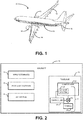
- FIG. 1 An exemplary aircraft 10 is illustrated graphically in FIG. 1 and further illustrated schematically in FIG. 2 .
- the example aircraft 10 is not intended to limit the model or type of aircraft in which the following systems and methods are capable of being utilized to suppress fire in cargo compartments. Accordingly, the systems and methods described herein may be applicable to any additional or alternative aircraft that include cargo compartments, known in the art.
- the aircraft 10 includes, at least, a fuselage 12, which includes at least one cargo compartment 20, wing assemblies 14, a propulsion system 16, and empennage 18.
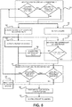
- the aircraft 10 further includes a fire suppression system 22, which includes a sensor system 24, one or more tanks 26 for storing a fire suppressant, at least one valve 28 for regulating flow of the fire suppressant to the compartment 20, and a controller 30.
- the system 22 is activated, whereby the controller 30 controls the valve(s) 28 to regulate a flow of the fire suppressant into the compartment 20.
- the fire suppression system 22 may be configured to only activate while the aircraft 10 is in flight.
- FIG. 3 a more detailed schematic depiction of the fire suppression system 22 is shown, illustrating elements of the fire suppression system 22 having exemplary placement or proximal relation to the compartment 20.
- the schematic depiction of FIG. 3 is not to scale and elements thereof are only depicted showing exemplary physical positioning and/or configuration of such elements.
- the controller 30 may be located outside of the compartment 20 (e.g., in a flight deck or electronics bay of the aircraft 10), the tanks 26 may be located just outside of the compartment 20 (e.g., along a side of the fuselage 12, at an aft end of the fuselage 12, etc.).
- FIG. 3 illustrates just one compartment 20, in examples wherein the aircraft 10 and/or fuselage 12 includes multiple compartments 20, the system 22 may be configured to provide fire suppression to multiple compartments 20 contained in the aircraft 10.
- the sensor system 24 is located, at least in part, in the compartment 20 and is configured to detect combustion products within the compartment 20, while being capable of differentiating or delineating between combustion products and a fire suppressant existing within atmospheric air in the compartment 20.
- the sensor system 24 includes a plurality of sensors 32, 34 that include one or more sensors configured for detecting atmospheric substances (e.g., fire suppressants, combustion products, and any other substance within air of the compartment 20) and one or more sensors configured for detecting combustion products.
- the sensor system 24 may include one or more photoelectric sensors 32 (also referred to as a first sensor(s) 32), which are configured to detect atmospheric substances by sensing a difference in visual obscuration level within the compartment 20, due to the existence of such atmospheric substances.
- these photoelectric sensors or first sensors 32 include an optical chamber that senses the difference in obscuration level, due to a foreign atmospheric substance, such as smoke from combustion products.
- photoelectric sensors 32 can quickly detect combustion products, such as smoke, indicative of a fire
- photoelectric sensors 32 can also detect other atmospheric substances, such as fire suppressant.
- the photoelectric sensors 32 are utilized in conjunction with one or more ionization sensors 34 (also referred to as a second sensor(s) 34).
- ionization sensors 34 are capable of detecting combustion products and/or fire only.
- ionization sensors 34 are configured to detect molecular ionization of combustion products from, for example, a fire. Therefore, the ionization sensors 34 are unaffected by the existence of the fire suppressant, as they do not rely on visual obscuration.
- the photoelectric sensors 32 may still sense obscuration, even if the fire is extinguished, due to the existence of the fire suppressant, while the ionization sensors 34 may cease to detect combustion products as the combustion event slows or ceases, in response to the fire suppressant. Therefore, by using a real-time comparison between the detections of the photoelectric sensors 32 and the ionization sensors 34, the sensor system 24 can differentiate between real combustion products associated with a fire and the fire suppressant used to suppress said fire. Such a comparison may be performed at the sensor level by the sensors of the sensor system 24, by an independent controller of the sensor system 24, and/or input from the sensor system 24 can be utilized by the controller 30 to perform such a comparison.
- the controller 30 is utilized to control flow of the fire suppressant, via the at least one valve 28, in response to input from the sensor system 24. Accordingly, the controller 30 is configured to provide instructions to discharge the fire suppressant, via the at least one valve 28, if the photoelectric sensor(s) 32 detect atmospheric substances and the ionization sensor(s) 34 detect combustion products.
- the controller 30 may be any electronic controller or computing system including a processor which operates to perform operations, execute control algorithms, store data, retrieve data, gather data, and/or any other computing or controlling task desired.
- the controller 30 may be a single controller or may include more than one controller disposed to control various functions and/or features of the fire suppression system 22 and/or the aircraft 10.
- the controller 30 may be implemented in hardware and/or software and may rely on one or more data maps relating to the operation of the fire suppression system 22 and/or the aircraft 10.
- the controller 30 may include internal memory and/or the controller 30 may be otherwise connected to external memory, such as a database or server.
- the internal memory and/or external memory may include, but are not limited to including, one or more of read only memory (ROM), random access memory (RAM), a portable memory, and the like.
- ROM read only memory
- RAM random access memory
- portable memory and the like.
- Such memory media are examples of nontransitory memory media.
- the at least one valve 28 can be any valve known in the art utilized to control the flow of gasses and/or liquids, such as fire suppressants, from a container, such as the tank(s) 26.
- the at least one valve 28 is a normally-open (NO) valve, while in some alternative examples, the at least one valve 28 is a normally-closed (NC) valve.
- Positioning of mechanisms of the at least one valve 28 are controlled by the controller 30, via one or more actuators connected to, embedded within, or otherwise associated with the at least one valve 28.
- the fire suppressant contained within the tank(s) 26 can be any suitable liquid and/or gaseous substance capable of suppressing fire within the compartment 20.
- the fire suppressant is Halon-1301, which is a trade name for the chemical bromotrifluoromethane.
- the Halon-1301 is a highly pressurized liquid contained in the one or more tank(s) 26 and released, during combustion events, via the at least one valve 28.
- Halon-1301 is commonly used as a fire suppressant in cargo compartments for commercial aircraft and, more specifically, is often utilized as a fire suppression agent in satisfaction of typical fire protection provisions provided by government authorities.
- the fire suppression system 22 further includes an alarm 36, which is capable of providing an alarm signal to an operator of the aircraft 10, an operator of the fire suppression system 22, a remote observant operator, and/or any other operator associated with the aircraft 10.
- the controller 30 is further configured to instruct the alarm 36 to provide the alarm signal to the operator if input from the sensor system 24 indicates that a fire or other combustion event has occurred.
- the alarm 36 may be configured to provide any type of alarm signal to the operator, such as, but not limited to, a visual alarm signal, an audible alarm signal, a tactile alarm signal, and the like.
- the system 22 includes one or more suppressant sensors 38, which are configured to determine concentration of the fire suppressant within the compartment 20.
- the controller 30 is operatively associated with the one or more suppressant sensors 38 and the instructions to discharge the fire suppressant are determined based, at least in part, on the concentration of the fire suppressant within the compartment 20.
- the one or more suppressant sensors 38 may be gas or particulate sensor(s) that draw a small amount of air into a chamber and then physically test the air for suppressant concentration. Accordingly, the one or more suppressant sensors 38 determine fire suppressant concentration and communicate such information to the controller 30.
- multiple suppressant sensors 38 are utilized to determine suppressant concentration at different locations within the compartment 20 and, in some further examples, such information may be used to determine composite suppressant concentration for the compartment 20.
- the suppressant sensor(s) 38 are configured to determine concentration of Halon-1301, within the compartment 20.
- the controller 30 compares the concentration of the fire suppressant, determined by the suppressant sensor(s) 38, with a desired concentration of the fire suppressant for the compartment 20 and instructions for discharging the fire suppressant are determined, at least in part, based on such a comparison.
- the desired concentration of the fire suppressant may be a desired suppressant concentration, either dictated by operator desires or regulatory restriction, that operators of the aircraft 10 desire to maintain during either flight or during and/or after a combustion event in the compartment 20.
- combustion products and/or fire suppressant may continue to linger in the compartment 20 and, in some examples, such lingering atmospheric substances may continue to cause the system 22 to activate the alarm 36 and/or dispense fire suppressant, when no fire exists.
- operators of the aircraft 10 may believe a combustion event or fire is occurring, when it has been suppressed.
- the fire suppression system 22 includes a filtration system 40 associated with the compartment 20 that is configured to remove combustion products from the compartment 20.
- the filtration system 40 includes one or more fans 42 and one or more filters 44.
- the filter(s) 44 are configured to remove combustion products from atmospheric air within the compartment 20.
- the fan(s) 42 are configured to draw the atmospheric air, and any substances contained therein, from the compartment 20 and towards the filter(s) 44.
- the filter(s) 44 remove combustion products from the air as it passes through the filter(s) 44.
- airflow generated by the fan(s) 42 recirculates the filtered atmospheric air back into the compartment 20.
- the filtration system 40 may maintain proper suppressant distribution in the compartment, as the airflow generated by the fan(s) 42 can draw the fire suppressant near the top of the compartment 20, where fire suppressant concentration may be lacking, in comparison to other portions of the compartment 20, as some fire suppressants are heavier than air and can settle to the bottom of a compartment
- the filter(s) 44 include one or more high-efficiency particulate air (HEPA) filters.
- HEPA filters filter particulate matter (e.g., combustion products, such as smoke) from atmospheric air by forcing said atmospheric air through a fine mesh, configured to be fine enough to filter out the undesired particulate.
- the filters 44 may be HEPA filters having a mesh sized such that the mesh filters substantially all combustion products out of the atmospheric air that passes through the filter(s) 44.
- the mesh of a HEPA filter of the filter(s) 44 may be sized such that the filter(s) 44 filter out substantially all combustion products, while allowing all or a substantial majority of particles of the fire suppressant to pass through the HEPA filter and recirculate into the compartment 20.
- the filter(s) 44 may be configured such that combustion products are filtered out of the atmospheric air, while fire suppressant is not filtered out of the atmospheric air.
- the filter(s) 44 are configured to allow Halon-1301 particles to pass through the filter(s) 44.
- FIG. 4 illustrates the schematic diagram of FIG. 3 , but in FIG. 4 the system 22 is in operation in response to a combustion event 50 (e.g., a fire in the compartment 20).
- a combustion event 50 e.g., a fire in the compartment 20.
- the schematic of FIGS. 3-4 is not to scale nor are any dimensional characteristics intended to show or imply any scale or magnitude of any elements or quantities thereof. Accordingly, the scale and quantity of substances shown are merely intended to show intended proximity of such substances, when the system 22 is in operation during the combustion event 50.
- the combustion event 50 generates combustion products 52 (depicted as area with vertical stripes), within the compartment 20.
- the controller 30 has instructed the at least one valve 28 to discharge a fire suppressant 54 (depicted as area with dotting) into the compartment 20.
- the fire suppressant 54 is intended to suppress the combustion event 50; however, the fire suppressant 54 may also commingle with the combustion products 52, within the compartment 20, as shown.
- the fan(s) 42 are disposed proximate to a compartment ceiling 56 of the compartment 20 and draw atmospheric air, including both the combustion products 52 and the fire suppressant 54, into a filtration compartment 58, which is disposed, at least in part, above the compartment ceiling 56.
- the fan(s) 42 for example, can be disposed substantially or in part flush with the compartment ceiling 56.
- the filter(s) 44 are disposed upstream of the fan(s) 42, within the filtration compartment 58, meaning atmospheric air drawn into the filtration compartment 58, by the fan(s) 42, enters the filter(s) 44 prior to passing through the fan(s) 42.
- the atmospheric air within the filtration compartment 58 may include both the combustion products 52 and the fire suppressant 54.
- the atmospheric air within the filtration compartment 58 is rid of substantially all combustion products 52, while still containing the fire suppressant 54.
- such filtered atmospheric air is then recirculated into the compartment 20, from the filtration compartment 58, via an exit 60 of the filtration compartment 58.
- FIG. 5 illustrates a flowchart for an example method 100 for suppressing fire in a cargo compartment of an aircraft.
- the method 100 is described, below, with reference to elements of the aircraft 10 and the fire suppression system 22, as described in detail above with reference to FIGS. 1-4 .
- the method 100 is certainly not limited to application in conjunction with aircraft 10 and/or the associated system 22 and the method 100 is capable of being performed on or using other systems and/or in the context of other aircraft.
- the method 100 begins at block 110, at which the sensor system 24 monitors the atmospheric air within the compartment 20. Accordingly, the photoelectric sensor(s) 32 determine the existence of atmospheric substances and the ionization sensor(s) 34 determine existence of combustion products. If no combustion products are detected, then the method 100 continues by continually monitoring the atmospheric air at block 110; however, if atmospheric substances and combustion products are detected, the method 100 proceeds to block 120 and, optionally, block 130.
- the fire suppressant is discharged into the compartment 20, via the at least one valve 28, as the sensor system 24 has determined that combustion products are present in the combustion chamber 20.
- the alarm 36 may be activated, as depicted in block 130.
- the method 100 includes activating the filtration system 40, as depicted in block 140.
- Activating the filtration system 40 initiates filtration, which includes directing the atmospheric air, at least in part, towards the filter(s) 44, using the fan(s) 42, filtering the combustion products, at least in part, out of the atmospheric air, using the filter(s) 44, and recirculating filtered atmospheric air into the cargo compartment 20, via airflow generated by the fan(s) 42.
- the method 100 includes monitoring fire suppressant concentration in the compartment 20 using the suppressant sensor(s) 38, as depicted in block 150. Such monitoring includes determining if concentration of the fire suppressant, within the atmospheric air of the compartment 20, deviates from an acceptable or desired fire suppressant concentration (e.g., the desired concentration, as discussed above). If the concentration deviates from the desired concentration, then the method 100 includes adjusting the fire suppressant flow, as depicted in block 160.
- an acceptable or desired fire suppressant concentration e.g., the desired concentration, as discussed above.
- Each of blocks 120, 140, 150, and 160 eventually flow to block 170, in which the method 100 includes further monitoring of the atmospheric air in the compartment 20, using the sensor system 24, similar to the monitoring of block 110, as depicted in block 170. If combustion products are still detected, the method 100 continues to execute blocks 140, 150, 160 throughout the remainder of the flight, until combustion products are no longer detected in the compartment 20.
- the method 100 may both return to block 110, wherein the atmospheric air is continually monitored to detect potential combustion events and/or combustion products, and the method 100 may proceed to blocks 180 and 190.
- the method 100 may include deactivating the filtration system 40, when combustion products are no longer detected in the compartment 20, as depicted in block 175.
- the controller 30 generates instructions, for the at least one valve 28, to maintain a fire suppressant concentration, within the compartment 20, as the current flight of the aircraft 10 is then continued to its landing destination, as depicted in block 190.
Landscapes
- Health & Medical Sciences (AREA)
- Public Health (AREA)
- Business, Economics & Management (AREA)
- Emergency Management (AREA)
- Fire-Extinguishing By Fire Departments, And Fire-Extinguishing Equipment And Control Thereof (AREA)
- Fire Alarms (AREA)
- Engineering & Computer Science (AREA)
- Operations Research (AREA)
- Filtering Of Dispersed Particles In Gases (AREA)
Abstract
Description
- The present disclosure relates generally to aircraft fire suppression systems and, more particularly, to atmospheric substance sensing within such aircraft fire suppression systems.
- Aircraft, particularly commercial aircraft, may include cargo compartments that are partitioned off from passenger compartments within the aircraft. As a safety measure, aircraft of this fashion may include fire suppression systems that are specifically associated with the cargo compartment(s). Such fire suppression systems may operate by introducing a fire suppressant into the compartment, once a combustion event or combustion products associated with a combustion event (e.g., a fire) are detected. In some examples of conventional fire suppression systems, the system may respond to a detected fire in two phases, a knockdown phase followed by a suppression phase. During the knockdown phase, the cargo compartment is flooded with fire suppressant at a high flow rate, whereas during the suppression phase, a lower flow rate of the fire suppressant is provided over an extended period of time.
- As the fire suppressants used in such systems may be gaseous or liquid particulates, during detection and/or monitoring phases of the fire suppression systems, the fire suppressants may commingle with combustion products, created by a combustion event. In conventional systems, sensors utilized to detect combustion events via detection of combustion products may provide false alarm signals, due to the existence of fire suppressants commingled with combustion products and/or the general atmospheric air of the cargo compartment. Therefore, false and/or nuisance alarms may cause a flight crew to take unnecessary measures when, in fact, any fire has already been adequately suppressed. Further, false alarms or false monitoring may indicate, to a controller, that excessive flow of fire suppressant is needed in an event wherein a combustion event has or is occurring and said event is, at least in part, suppressed. Therefore, fire suppressant systems, which can accurately delineate between atmospheric substances and combustion products within the atmospheric air of the compartment, are desired. Additionally, fire suppressant systems that include smoke removal for further elimination of false alarms and decreased likelihood of smoke penetration, into the occupied areas of the airplane, are also desired.
- In accordance with one example, a fire suppression system for a compartment of an aircraft is disclosed. The system includes a sensor system, at least one valve, and a controller. The sensor system is located within the compartment and includes, at least, a first sensor and a second sensor. The first sensor is configured to detect atmospheric substances within the compartment and the second sensor is configured to detect combustion products within the compartment. The at least one valve is configured for regulating flow of a fire suppressant to the compartment. The controller is configured to control flow of the fire suppressant, via the at least one valve, in response to input from the sensor system. The controller provides instructions to discharge the fire suppressant if the first sensor detects atmospheric substances and the second sensor detects combustion products.
- In a refinement, the system further includes an alarm capable of providing an alarm signal to an operator and the controller is further configured to provide the alarm signal to the operator if the first sensor detects atmospheric substances and the second sensor detects combustion products.
- In another refinement, the first sensor is a photoelectric sensor configured to detect atmospheric substances by sensing a difference in obscuration level within the chamber due to existence of atmospheric substances.
- In another refinement, the second sensor is an ionization sensor configured to detect molecular ionization of combustion from a fire.
- In another refinement, the system further includes a filtration system associated with the compartment and configured to remove combustion products from the compartment.
- In a further refinement, the filtration system includes a filter configured to remove combustion products from atmospheric air within the compartment and a fan to draw the atmospheric air from the compartment towards the filter and recirculate the atmospheric air into the compartment.
- In another refinement, the system further includes at least one suppressant sensor configured to determine concentration of the fire suppressant within the compartment and the controller is operatively associated with the at least one suppressant sensor and the instructions to discharge the fire suppressant are determined, by the controller, based, at least in part, on the concentration of the fire suppressant within the compartment.
- In a further refinement, the fire suppressant is Halon-1301 and the at least one suppressant sensor is configured to determine concentration of Halon-1301 within the compartment.
- In another further refinement, the controller is further configured to compare the concentration of the fire suppressant within the compartment with a desired concentration of the fire suppressant for the compartment and the instructions to discharge the fire suppressant are determined, by the controller, based, at least in part, on the comparison of the concentration of the fire suppressant within the compartment and the desired concentration of the fire suppressant for the compartment.
- In accordance with another example, a fire suppression system for a compartment of an aircraft is disclosed. The system includes a sensor system, at least one valve, a controller, at least one filter, and at least one fan. The sensor system is located within the compartment and is configured to detect combustion products within the compartment while being capable of differentiating between combustion products and a fire suppressant existing in the compartment. The at least one valve is for regulating flow of the fire suppressant to the compartment. The controller is configured to control flow of the fire suppressant, via the at least one valve, in response to input from the sensor, the controller providing instructions to discharge the fire suppressant if the sensor system detects combustion products within the compartment. The at least one filter is configured to remove combustion products from atmospheric air within the compartment. The at least one fan is configured to draw the atmospheric air from the compartment towards the at least one filter and recirculate the atmospheric air into the compartment.
- In a refinement, the at least one filter includes a high-efficiency particulate air (HEPA) filter.
- In a further refinement, the HEPA filter is configured such that it filters combustion products out of the atmospheric air, while allowing a substantial majority of particles of the fire suppressant to pass through the HEPA filter and recirculate into the compartment.
- In a further refinement, the fire suppressant is Halon-1301 and the HEPA filter is configured such that it allows a substantial majority of Halon-1301 particles to pass through the HEPA filter and recirculate into the compartment.
- In another refinement, the at least one fan is disposed proximate to a compartment ceiling of the compartment and the at least one fan draws the atmospheric air into a filtration compartment disposed, in part, above the compartment ceiling, the at least one filter is disposed upstream of the at least one fan and within the filtration compartment and, after passing through the filter, the atmospheric air is recirculated into the compartment, from the filtration compartment, via an exit of the filtration compartment.
- In accordance with yet another example, a method of suppressing fire in a cargo compartment of an aircraft is disclosed. The method includes monitoring atmospheric air in the cargo compartment utilizing input from a sensor system. The sensor system is configured to determine if atmospheric substances are present in the atmospheric air and to determine if combustion products are present in the atmospheric air. The method further includes discharging a fire suppressant into the cargo compartment, via at least one valve, if the sensor system determines that atmospheric substances are present in the atmospheric air and combustion products are present in the atmospheric air.
- In a refinement, the method further includes continuing to monitor the atmospheric air in the cargo compartment if the sensor system detects atmospheric substances and does not detect combustion products.
- In another refinement, the method further includes activating an alarm if the sensor system determines that atmospheric substances are present in the atmospheric air and combustion products are present in the atmospheric air.
- In another refinement, the method further includes monitoring concentration of the fire suppressant within the atmospheric air, using a fire suppressant sensor and adjusting flow of the fire suppressant to the cargo compartment, via the at least one valve, if input from the fire suppressant sensor indicates that a current fire suppressant concentration deviates from a desired fire suppressant concentration.
- In another refinement, the method includes activating a filtration system, if the sensor system determines that atmospheric substances are present in the atmospheric air and combustion products are present in the atmospheric air.
- In a further refinement, the method further includes directing the atmospheric air, at least in part, towards a filter of the filtration system, using a fan of the filtration system, filtering the combustion products, at least in part, out of the atmospheric air, using the filter, and recirculating filtered atmospheric air into the cargo compartment via airflow generated by the fan.
- These and other aspects and features will become more readily apparent upon reading the following detailed description when taken in conjunction with the accompanying drawings. In addition, although various features are disclosed in relation to specific examples, it is understood that the various features may be combined with each other, or used alone, with any of the various examples without departing from the scope of the disclosure.
-
-
FIG. 1 is a perspective view of an example aircraft, in accordance with the present disclosure. -
FIG. 2 is a schematic block diagram of the aircraft ofFIG. 1 , illustrating select elements of a fire suppression system on board the aircraft, in accordance with an example of the disclosure. -
FIG. 3 is a detailed schematic block diagram of the fire suppression system ofFIG. 2 , illustrating implementation of the fire suppression system relative to a compartment of the aircraft, in accordance withFIGS. 1-2 and the present disclosure. -
FIG. 4 is another illustration of the schematic block diagram of the fire suppression system ofFIG. 3 , in which a combustion event has occurred or is occurring, illustrating exemplary flow and/or distribution of atmospheric substances and/or particles within the compartment, in accordance withFIGS. 1-3 and the present disclosure. -
FIG. 5 is an exemplary flowchart for a method for suppressing fire within a cargo compartment of an aircraft, in accordance with an example of the present disclosure. - While the present disclosure is susceptible to various modifications and alternative constructions, certain illustrative examples thereof will be shown and described below in detail. The disclosure is not limited to the specific examples disclosed, but instead includes all modifications, alternative constructions, and equivalents thereof.
- An
exemplary aircraft 10 is illustrated graphically inFIG. 1 and further illustrated schematically inFIG. 2 . Theexample aircraft 10 is not intended to limit the model or type of aircraft in which the following systems and methods are capable of being utilized to suppress fire in cargo compartments. Accordingly, the systems and methods described herein may be applicable to any additional or alternative aircraft that include cargo compartments, known in the art. - To that end, the
aircraft 10 includes, at least, afuselage 12, which includes at least onecargo compartment 20,wing assemblies 14, apropulsion system 16, andempennage 18. Theaircraft 10 further includes afire suppression system 22, which includes asensor system 24, one ormore tanks 26 for storing a fire suppressant, at least onevalve 28 for regulating flow of the fire suppressant to thecompartment 20, and acontroller 30. When a fire or combustion event is detected in thecompartment 20, thesystem 22 is activated, whereby thecontroller 30 controls the valve(s) 28 to regulate a flow of the fire suppressant into thecompartment 20. In some examples, thefire suppression system 22 may be configured to only activate while theaircraft 10 is in flight. - Turning now to
FIG. 3 , a more detailed schematic depiction of thefire suppression system 22 is shown, illustrating elements of thefire suppression system 22 having exemplary placement or proximal relation to thecompartment 20. Of course, the schematic depiction ofFIG. 3 is not to scale and elements thereof are only depicted showing exemplary physical positioning and/or configuration of such elements. To that end, thecontroller 30 may be located outside of the compartment 20 (e.g., in a flight deck or electronics bay of the aircraft 10), thetanks 26 may be located just outside of the compartment 20 (e.g., along a side of thefuselage 12, at an aft end of thefuselage 12, etc.). Further, while the example ofFIG. 3 illustrates just onecompartment 20, in examples wherein theaircraft 10 and/orfuselage 12 includesmultiple compartments 20, thesystem 22 may be configured to provide fire suppression tomultiple compartments 20 contained in theaircraft 10. - The
sensor system 24, as depicted, is located, at least in part, in thecompartment 20 and is configured to detect combustion products within thecompartment 20, while being capable of differentiating or delineating between combustion products and a fire suppressant existing within atmospheric air in thecompartment 20. To that end, thesensor system 24 includes a plurality ofsensors sensor system 24 may include one or more photoelectric sensors 32 (also referred to as a first sensor(s) 32), which are configured to detect atmospheric substances by sensing a difference in visual obscuration level within thecompartment 20, due to the existence of such atmospheric substances. In some examples, these photoelectric sensors orfirst sensors 32 include an optical chamber that senses the difference in obscuration level, due to a foreign atmospheric substance, such as smoke from combustion products. - While
photoelectric sensors 32 can quickly detect combustion products, such as smoke, indicative of a fire,photoelectric sensors 32 can also detect other atmospheric substances, such as fire suppressant. Accordingly, in some examples, thephotoelectric sensors 32 are utilized in conjunction with one or more ionization sensors 34 (also referred to as a second sensor(s) 34). These second orionization sensors 34 are capable of detecting combustion products and/or fire only. Particularly,ionization sensors 34 are configured to detect molecular ionization of combustion products from, for example, a fire. Therefore, theionization sensors 34 are unaffected by the existence of the fire suppressant, as they do not rely on visual obscuration. - For example, if a combustion event occurs and the fire suppressant is discharged in the
compartment 20, thephotoelectric sensors 32 may still sense obscuration, even if the fire is extinguished, due to the existence of the fire suppressant, while theionization sensors 34 may cease to detect combustion products as the combustion event slows or ceases, in response to the fire suppressant. Therefore, by using a real-time comparison between the detections of thephotoelectric sensors 32 and theionization sensors 34, thesensor system 24 can differentiate between real combustion products associated with a fire and the fire suppressant used to suppress said fire. Such a comparison may be performed at the sensor level by the sensors of thesensor system 24, by an independent controller of thesensor system 24, and/or input from thesensor system 24 can be utilized by thecontroller 30 to perform such a comparison. - The
controller 30 is utilized to control flow of the fire suppressant, via the at least onevalve 28, in response to input from thesensor system 24. Accordingly, thecontroller 30 is configured to provide instructions to discharge the fire suppressant, via the at least onevalve 28, if the photoelectric sensor(s) 32 detect atmospheric substances and the ionization sensor(s) 34 detect combustion products. Thecontroller 30 may be any electronic controller or computing system including a processor which operates to perform operations, execute control algorithms, store data, retrieve data, gather data, and/or any other computing or controlling task desired. Thecontroller 30 may be a single controller or may include more than one controller disposed to control various functions and/or features of thefire suppression system 22 and/or theaircraft 10. Functionality of thecontroller 30 may be implemented in hardware and/or software and may rely on one or more data maps relating to the operation of thefire suppression system 22 and/or theaircraft 10. To that end, thecontroller 30 may include internal memory and/or thecontroller 30 may be otherwise connected to external memory, such as a database or server. The internal memory and/or external memory may include, but are not limited to including, one or more of read only memory (ROM), random access memory (RAM), a portable memory, and the like. Such memory media are examples of nontransitory memory media. - The at least one
valve 28 can be any valve known in the art utilized to control the flow of gasses and/or liquids, such as fire suppressants, from a container, such as the tank(s) 26. In some examples the at least onevalve 28 is a normally-open (NO) valve, while in some alternative examples, the at least onevalve 28 is a normally-closed (NC) valve. Positioning of mechanisms of the at least onevalve 28 are controlled by thecontroller 30, via one or more actuators connected to, embedded within, or otherwise associated with the at least onevalve 28. - The fire suppressant contained within the tank(s) 26 can be any suitable liquid and/or gaseous substance capable of suppressing fire within the
compartment 20. In some, non-limiting examples, the fire suppressant is Halon-1301, which is a trade name for the chemical bromotrifluoromethane. In such examples, the Halon-1301 is a highly pressurized liquid contained in the one or more tank(s) 26 and released, during combustion events, via the at least onevalve 28. Halon-1301is commonly used as a fire suppressant in cargo compartments for commercial aircraft and, more specifically, is often utilized as a fire suppression agent in satisfaction of typical fire protection provisions provided by government authorities. - In some examples, the
fire suppression system 22 further includes analarm 36, which is capable of providing an alarm signal to an operator of theaircraft 10, an operator of thefire suppression system 22, a remote observant operator, and/or any other operator associated with theaircraft 10. In such examples, thecontroller 30 is further configured to instruct thealarm 36 to provide the alarm signal to the operator if input from thesensor system 24 indicates that a fire or other combustion event has occurred. Thealarm 36 may be configured to provide any type of alarm signal to the operator, such as, but not limited to, a visual alarm signal, an audible alarm signal, a tactile alarm signal, and the like. - To determine information regarding fire suppressant concentration in the
compartment 20, in some examples, thesystem 22 includes one ormore suppressant sensors 38, which are configured to determine concentration of the fire suppressant within thecompartment 20. In such examples, thecontroller 30 is operatively associated with the one ormore suppressant sensors 38 and the instructions to discharge the fire suppressant are determined based, at least in part, on the concentration of the fire suppressant within thecompartment 20. The one ormore suppressant sensors 38 may be gas or particulate sensor(s) that draw a small amount of air into a chamber and then physically test the air for suppressant concentration. Accordingly, the one ormore suppressant sensors 38 determine fire suppressant concentration and communicate such information to thecontroller 30. In some examples,multiple suppressant sensors 38 are utilized to determine suppressant concentration at different locations within thecompartment 20 and, in some further examples, such information may be used to determine composite suppressant concentration for thecompartment 20. In the aforementioned examples wherein the fire suppressant is Halon-1301, the suppressant sensor(s) 38 are configured to determine concentration of Halon-1301, within thecompartment 20. - In some examples, the
controller 30 compares the concentration of the fire suppressant, determined by the suppressant sensor(s) 38, with a desired concentration of the fire suppressant for thecompartment 20 and instructions for discharging the fire suppressant are determined, at least in part, based on such a comparison. The desired concentration of the fire suppressant may be a desired suppressant concentration, either dictated by operator desires or regulatory restriction, that operators of theaircraft 10 desire to maintain during either flight or during and/or after a combustion event in thecompartment 20. - Even in scenarios wherein a combustion event or fire is suppressed or partially suppressed, combustion products and/or fire suppressant may continue to linger in the
compartment 20 and, in some examples, such lingering atmospheric substances may continue to cause thesystem 22 to activate thealarm 36 and/or dispense fire suppressant, when no fire exists. In such scenarios, operators of theaircraft 10 may believe a combustion event or fire is occurring, when it has been suppressed. Accordingly, in some examples, thefire suppression system 22 includes afiltration system 40 associated with thecompartment 20 that is configured to remove combustion products from thecompartment 20. - The
filtration system 40 includes one ormore fans 42 and one or more filters 44. The filter(s) 44 are configured to remove combustion products from atmospheric air within thecompartment 20. Further, the fan(s) 42 are configured to draw the atmospheric air, and any substances contained therein, from thecompartment 20 and towards the filter(s) 44. As the atmospheric air passes through the filter(s) 44, via air flow generated by the fan(s) 42, the filter(s) 44 remove combustion products from the air as it passes through the filter(s) 44. After filtration, airflow generated by the fan(s) 42 recirculates the filtered atmospheric air back into thecompartment 20. As an additional benefit, thefiltration system 40 may maintain proper suppressant distribution in the compartment, as the airflow generated by the fan(s) 42 can draw the fire suppressant near the top of thecompartment 20, where fire suppressant concentration may be lacking, in comparison to other portions of thecompartment 20, as some fire suppressants are heavier than air and can settle to the bottom of a compartment - In some examples, the filter(s) 44 include one or more high-efficiency particulate air (HEPA) filters. HEPA filters filter particulate matter (e.g., combustion products, such as smoke) from atmospheric air by forcing said atmospheric air through a fine mesh, configured to be fine enough to filter out the undesired particulate. Accordingly, in such examples the
filters 44 may be HEPA filters having a mesh sized such that the mesh filters substantially all combustion products out of the atmospheric air that passes through the filter(s) 44. Furthermore, the mesh of a HEPA filter of the filter(s) 44 may be sized such that the filter(s) 44 filter out substantially all combustion products, while allowing all or a substantial majority of particles of the fire suppressant to pass through the HEPA filter and recirculate into thecompartment 20. In other words, the filter(s) 44 may be configured such that combustion products are filtered out of the atmospheric air, while fire suppressant is not filtered out of the atmospheric air. In the aforementioned examples wherein the fire suppressant is Halon-1301, the filter(s) 44 are configured to allow Halon-1301 particles to pass through the filter(s) 44. - To graphically illustrate such selective filtration performed by the
filtration system 40,FIG. 4 illustrates the schematic diagram ofFIG. 3 , but inFIG. 4 thesystem 22 is in operation in response to a combustion event 50 (e.g., a fire in the compartment 20). As mentioned above, the schematic ofFIGS. 3-4 is not to scale nor are any dimensional characteristics intended to show or imply any scale or magnitude of any elements or quantities thereof. Accordingly, the scale and quantity of substances shown are merely intended to show intended proximity of such substances, when thesystem 22 is in operation during thecombustion event 50. - As depicted, the
combustion event 50 generates combustion products 52 (depicted as area with vertical stripes), within thecompartment 20. In reaction to thecombustion products 52 being detected by thesensor system 24, thecontroller 30 has instructed the at least onevalve 28 to discharge a fire suppressant 54 (depicted as area with dotting) into thecompartment 20. Thefire suppressant 54 is intended to suppress thecombustion event 50; however, thefire suppressant 54 may also commingle with thecombustion products 52, within thecompartment 20, as shown. - The fan(s) 42 are disposed proximate to a
compartment ceiling 56 of thecompartment 20 and draw atmospheric air, including both thecombustion products 52 and thefire suppressant 54, into afiltration compartment 58, which is disposed, at least in part, above thecompartment ceiling 56. The fan(s) 42, for example, can be disposed substantially or in part flush with thecompartment ceiling 56. The filter(s) 44 are disposed upstream of the fan(s) 42, within thefiltration compartment 58, meaning atmospheric air drawn into thefiltration compartment 58, by the fan(s) 42, enters the filter(s) 44 prior to passing through the fan(s) 42. Prior to entering the filter(s) 44 for filtration, as shown, the atmospheric air within thefiltration compartment 58 may include both thecombustion products 52 and thefire suppressant 54. After exiting the filter(s) 44, as shown, the atmospheric air within thefiltration compartment 58 is rid of substantially allcombustion products 52, while still containing thefire suppressant 54. Upon passing through the filter(s) 44, such filtered atmospheric air is then recirculated into thecompartment 20, from thefiltration compartment 58, via anexit 60 of thefiltration compartment 58. - By utilizing the systems and methods disclosed herein, false fire alarms can be prevented, fire suppressant overuse can be limited, thus reducing costs, and greater air filtration can be achieved. To that end,
FIG. 5 illustrates a flowchart for anexample method 100 for suppressing fire in a cargo compartment of an aircraft. Themethod 100 is described, below, with reference to elements of theaircraft 10 and thefire suppression system 22, as described in detail above with reference toFIGS. 1-4 . However, themethod 100 is certainly not limited to application in conjunction withaircraft 10 and/or the associatedsystem 22 and themethod 100 is capable of being performed on or using other systems and/or in the context of other aircraft. - The
method 100 begins atblock 110, at which thesensor system 24 monitors the atmospheric air within thecompartment 20. Accordingly, the photoelectric sensor(s) 32 determine the existence of atmospheric substances and the ionization sensor(s) 34 determine existence of combustion products. If no combustion products are detected, then themethod 100 continues by continually monitoring the atmospheric air atblock 110; however, if atmospheric substances and combustion products are detected, themethod 100 proceeds to block 120 and, optionally, block 130. - At
block 120, the fire suppressant is discharged into thecompartment 20, via the at least onevalve 28, as thesensor system 24 has determined that combustion products are present in thecombustion chamber 20. Optionally, in response to the detection of combustion products, thealarm 36 may be activated, as depicted inblock 130. - Concurrent or shortly subsequent to the discharge of fire suppressant of
block 120, themethod 100 includes activating thefiltration system 40, as depicted inblock 140. Activating thefiltration system 40 initiates filtration, which includes directing the atmospheric air, at least in part, towards the filter(s) 44, using the fan(s) 42, filtering the combustion products, at least in part, out of the atmospheric air, using the filter(s) 44, and recirculating filtered atmospheric air into thecargo compartment 20, via airflow generated by the fan(s) 42. - In some examples, the
method 100 includes monitoring fire suppressant concentration in thecompartment 20 using the suppressant sensor(s) 38, as depicted inblock 150. Such monitoring includes determining if concentration of the fire suppressant, within the atmospheric air of thecompartment 20, deviates from an acceptable or desired fire suppressant concentration (e.g., the desired concentration, as discussed above). If the concentration deviates from the desired concentration, then themethod 100 includes adjusting the fire suppressant flow, as depicted inblock 160. - Each of
blocks method 100 includes further monitoring of the atmospheric air in thecompartment 20, using thesensor system 24, similar to the monitoring ofblock 110, as depicted inblock 170. If combustion products are still detected, themethod 100 continues to executeblocks compartment 20. - When combustion products are no longer detected in the
compartment 20, themethod 100 may both return to block 110, wherein the atmospheric air is continually monitored to detect potential combustion events and/or combustion products, and themethod 100 may proceed toblocks method 100 may include deactivating thefiltration system 40, when combustion products are no longer detected in thecompartment 20, as depicted inblock 175. Atblock 180, thecontroller 30 generates instructions, for the at least onevalve 28, to maintain a fire suppressant concentration, within thecompartment 20, as the current flight of theaircraft 10 is then continued to its landing destination, as depicted inblock 190. - Set out below are a series of clauses that disclose features of further aspects of the invention, which may be claimed. The clauses that do not refer to a preceding clause contain essential features of that aspect; the clauses that do refer to one or more preceding clause contain optional features of that aspect.
- Clause 1. A fire suppression system for a compartment of an aircraft, the system comprising:
- a sensor system located within the compartment, the sensor system including, at least, a first sensor and a second sensor, the first sensor configured to detect atmospheric substances within the compartment and the second sensor configured to detect combustion products within the compartment;
- at least one valve for regulating flow of a fire suppressant to the compartment; and
- a controller configured to control flow of the fire suppressant, via the at least one valve, in response to input from the sensor system, the controller providing instructions to discharge the fire suppressant if the first sensor detects atmospheric substances and the second sensor detects combustion products.
- Clause 2. The fire suppression system of Clause 1, further comprising an alarm capable of providing an alarm signal to an operator, and
wherein the controller is further configured to instruct the alarm to provide the alarm signal to the operator if the first sensor detects atmospheric substances and the second sensor detects combustion products. - Clause 3. The fire suppression system of Clause 1 or Clause 2, wherein the first sensor is a photoelectric sensor configured to detect atmospheric substances by sensing a difference in obscuration level within the compartment due to existence of atmospheric substances.
- Clause 4. The fire suppression system of any of Clauses 1, 2, or 3 wherein the second sensor is an ionization sensor configured to detect combustion products.
- Clause 5. The fire suppression system of any of Clauses 1 to 4, including a filtration system associated with the compartment and configured to remove combustion products from the compartment.
- Clause 6. The fire suppression system of Clause 5, wherein the filtration system includes:
- a filter configured to remove combustion products from atmospheric air within the compartment;
- a fan to draw the atmospheric air from the compartment towards the filter and recirculate the atmospheric air into the compartment.
- Clause 7. The fire suppression system of any of Clauses 1 to 6, further comprising at least one suppressant sensor configured to determine concentration of the fire suppressant within the compartment, and
wherein the controller is operatively associated with the at least one suppressant sensor and the instructions to discharge the fire suppressant are determined, by the controller, based, at least in part, on the concentration of the fire suppressant within the compartment. - Clause 8. The fire suppression system of Clause 7, wherein the fire suppressant is Halon-1301 and the at least one suppressant sensor is configured to determine concentration of Halon-1301 within the compartment.
- Clause 9. The fire suppression system of Clause 7 or Clause 8, wherein the controller is further configured to compare the concentration of the fire suppressant within the compartment with a desired concentration of the fire suppressant for the compartment, and
wherein the instructions to discharge the fire suppressant are determined, by the controller, based, at least in part, on the comparison of the concentration of the fire suppressant within the compartment and the desired concentration of the fire suppressant for the compartment. -
Clause 10. A fire suppression system for a compartment of an aircraft, the system comprising:- a sensor system located within the compartment, the sensor system configured to detect combustion products within the compartment while being capable of differentiating between combustion products and a fire suppressant existing in the compartment;
- at least one valve for regulating flow of the fire suppressant to the compartment;
- a controller configured to control flow of the fire suppressant, via the at least one valve, in response to input from the sensor system, the controller providing instructions to discharge the fire suppressant if the sensor system detects combustion products within the compartment;
- at least one filter configured to remove combustion products from atmospheric air within the compartment; and
- at least one fan configured to draw the atmospheric air from the compartment towards the at least one filter and recirculate the atmospheric air into the compartment.
- Clause 11. The fire suppression system of
Clause 10, wherein the at least one filter includes a high-efficiency particulate air (HEPA) filter. -
Clause 12. The fire suppression system of Clause 11, wherein the HEPA filter is configured such that it filters combustion products out of the atmospheric air, while allowing a substantial majority of particles of the fire suppressant to pass through the HEPA filter and recirculate into the compartment. - Clause 13. The fire suppression system of any of
Clauses 11 or 12, wherein the fire suppressant is Halon-1301 and wherein the HEPA filter is configured such that it allows a substantial majority of Halon-1301 particles to pass through the HEPA filter and recirculate into the compartment. -
Clause 14. The fire suppression system of any ofClauses 10 to 13, wherein the at least one fan is proximate to a compartment ceiling of the compartment and the at least one fan draws the atmospheric air into a filtration compartment disposed, in part, above the compartment ceiling,
wherein the at least one filter is disposed upstream of the at least one fan and within the filtration compartment, and
wherein, after passing through the filter, the atmospheric air is recirculated into the compartment, from the filtration compartment, via an exit of the filtration compartment. - Clause 15. A method of suppressing fire in a cargo compartment of an aircraft, the method comprising:
- monitoring atmospheric air in the cargo compartment utilizing input from a sensor system, the sensor system configured to determine if atmospheric substances are present in the atmospheric air and to determine if combustion products are present in the atmospheric air; and
- discharging a fire suppressant into the cargo compartment, via at least one valve, if the sensor system determines that atmospheric substances are present in the atmospheric air and combustion products are present in the atmospheric air.
-
Clause 16. The method of Clause 15, further comprising continuing to monitor the atmospheric air in the cargo compartment if the sensor system detects atmospheric gas and does not detect combustion products. - Clause 17. The method of any of
Clauses 15 or 16, further comprising activating an alarm if the sensor system determines that atmospheric substances are present in the atmospheric air and combustion products are present in the atmospheric air. -
Clause 18. The method of any of Clauses 15 to 17, further comprising monitoring concentration of the fire suppressant within the atmospheric air, using a fire suppressant sensor; and
adjusting flow of the fire suppressant to the cargo compartment, via the at least one valve, if input from the fire suppressant sensor indicates that a current fire suppressant concentration deviates from a desired fire suppressant concentration. - Clause 19. The method of any of Clauses 15 to 18, further comprising activating a filtration system, if the sensor system determines that atmospheric substances are present in the atmospheric air and combustion products are present in the atmospheric air.
-
Clause 20. The method of Clause 19, further comprising directing the atmospheric air, at least in part, towards a filter of the filtration system, using a fan of the filtration system;
filtering the combustion products, at least in part, out of the atmospheric air, using the filter; and
recirculating filtered atmospheric air into the cargo compartment via airflow generated by the fan.
Claims (15)
- A fire suppression system (22) for a compartment (20) of an aircraft (10), the system (22) comprising:a sensor system (24) located within the compartment (20), the sensor system (24) including, at least, a first sensor (32) and a second sensor (34), the first sensor (32) configured to detect atmospheric substances within the compartment (20) and the second sensor (34) configured to detect combustion products within the compartment (20);at least one valve (28) for regulating flow of a fire suppressant (54) to the compartment (20); anda controller (30) configured to control flow of the fire suppressant, via the at least one valve (28), in response to input from the sensor system (24), the controller (30) providing instructions to discharge the fire suppressant (54) if the first sensor (32) detects atmospheric substances and the second sensor (34) detects combustion products.
- The fire suppression system (22) of claim 1, further comprising an alarm (36) capable of providing an alarm signal to an operator, and
wherein the controller (30) is further configured to instruct the alarm (36) to provide the alarm signal to the operator if the first sensor (32) detects atmospheric substances and the second sensor (34) detects combustion products. - The fire suppression system (22) of claim 1 or 2, wherein the first sensor (32) is a photoelectric sensor (32) configured to detect atmospheric substances by sensing a difference in obscuration level within the compartment (20) due to existence of atmospheric substances and the second sensor (34) is an ionization sensor (34) configured to detect combustion products.
- The fire suppression system (22) of any one of claims 1-3, including a filtration system (40) associated with the compartment (20) and configured to remove combustion products from the compartment (20).
- The fire suppression system (22) of claim 4, wherein the filtration system (40) includes:a filter (44) configured to remove combustion products from atmospheric air within the compartment (20);a fan (42) to draw the atmospheric air from the compartment (20) towards the filter (44) and recirculate the atmospheric air into the compartment (20).
- The fire suppression system (22) of any one of claims 1-5, further comprising at least one suppressant sensor (38) configured to determine concentration of the fire suppressant (54) within the compartment (20), and
wherein the controller (30) is operatively associated with the at least one suppressant sensor (38) and the instructions to discharge the fire suppressant (54) are determined, by the controller (30), based, at least in part, on the concentration of the fire suppressant (54) within the compartment (20). - The fire suppression system (22) of claim 6, wherein the fire suppressant (54) is Halon-1301 and the at least one suppressant sensor (38) is configured to determine concentration of Halon-1301 within the compartment (20).
- The fire suppression system (22) of claim 6 or claim 7, wherein the controller (30) is further configured to compare the concentration of the fire suppressant (54) within the compartment (20) with a desired concentration of the fire suppressant (54) for the compartment (20), and
wherein the instructions to discharge the fire suppressant (54) are determined, by the controller (30), based, at least in part, on the comparison of the concentration of the fire suppressant (54) within the compartment (20) and the desired concentration of the fire suppressant (54) for the compartment (20). - A fire suppression system (22) for a compartment (20) of an aircraft (10), the system comprising:a sensor system (24) located within the compartment (20), the sensor system (24) configured to detect combustion products within the compartment (20) while being capable of differentiating between combustion products and a fire suppressant (54) existing in the compartment (20);at least one valve (28) for regulating flow of the fire suppressant (54) to the compartment (20);a controller (30) configured to control flow of the fire suppressant (54), via the at least one valve (28), in response to input from the sensor system (24), the controller (30) providing instructions to discharge the fire suppressant (54) if the sensor system (24) detects combustion products within the compartment (20);at least one filter (44) configured to remove combustion products from atmospheric air within the compartment (20); andat least one fan (42) configured to draw the atmospheric air from the compartment (20) towards the at least one filter (44) and recirculate the atmospheric air into the compartment (20).
- The fire suppression system (22) of claim 9, wherein the at least one fan (42) is proximate to a compartment ceiling (56) of the compartment (20) and the at least one fan (42) draws the atmospheric air into a filtration compartment (58) disposed, in part, above the compartment ceiling (56),
wherein the at least one filter (44) is disposed upstream of the at least one fan (42) and within the filtration compartment (58), and
wherein, after passing through the filter (44), the atmospheric air is recirculated into the compartment (20), from the filtration compartment (58), via an exit (60) of the filtration compartment (58). - A method (100) of suppressing fire in a cargo compartment of an aircraft, the method (100) comprising:monitoring (110) atmospheric air in the cargo compartment utilizing input from a sensor system, the sensor system configured to determine if atmospheric substances are present in the atmospheric air and to determine if combustion products are present in the atmospheric air; anddischarging (120) a fire suppressant into the cargo compartment, via at least one valve, if the sensor system determines that atmospheric substances are present in the atmospheric air and combustion products are present in the atmospheric air.
- The method (100) of claim 11, further comprising continuing to monitor the atmospheric air in the cargo compartment if the sensor system detects atmospheric gas and does not detect combustion products.
- The method (100) of claim 11 or 12, further comprising activating (130) an alarm if the sensor system determines that atmospheric substances are present in the atmospheric air and combustion products are present in the atmospheric air.
- The method (100) of any one of claims 11-13, further comprising monitoring (150) concentration of the fire suppressant within the atmospheric air, using a fire suppressant sensor; and
adjusting flow (160) of the fire suppressant to the cargo compartment, via the at least one valve, if input from the fire suppressant sensor indicates that a current fire suppressant concentration deviates from a desired fire suppressant concentration. - The method (100) of any one of claims 11-14, further comprising activating (140) a filtration system, if the sensor system determines that atmospheric substances are present in the atmospheric air and combustion products are present in the atmospheric air;
directing the atmospheric air, at least in part, towards a filter of the filtration system, using a fan of the filtration system;
filtering the combustion products, at least in part, out of the atmospheric air, using the filter; and
recirculating filtered atmospheric air into the cargo compartment via airflow generated by the fan.
Applications Claiming Priority (1)
| Application Number | Priority Date | Filing Date | Title |
|---|---|---|---|
| US15/434,979 US10265561B2 (en) | 2017-02-16 | 2017-02-16 | Atmospheric air monitoring for aircraft fire suppression |
Publications (3)
| Publication Number | Publication Date |
|---|---|
| EP3384965A2 true EP3384965A2 (en) | 2018-10-10 |
| EP3384965A3 EP3384965A3 (en) | 2019-01-09 |
| EP3384965B1 EP3384965B1 (en) | 2021-04-28 |
Family
ID=61132328
Family Applications (1)
| Application Number | Title | Priority Date | Filing Date |
|---|---|---|---|
| EP18154737.3A Active EP3384965B1 (en) | 2017-02-16 | 2018-02-01 | Atmospheric air monitoring for aircraft fire suppression |
Country Status (6)
| Country | Link |
|---|---|
| US (1) | US10265561B2 (en) |
| EP (1) | EP3384965B1 (en) |
| CN (1) | CN108434632B (en) |
| AU (1) | AU2018200875B2 (en) |
| BR (1) | BR102018001115B1 (en) |
| CA (1) | CA2988758C (en) |
Families Citing this family (5)
| Publication number | Priority date | Publication date | Assignee | Title |
|---|---|---|---|---|
| US10479525B2 (en) * | 2018-04-03 | 2019-11-19 | Kidde Technologies, Inc. | Utilization of engine bleed air to provide extended duration emergency aircraft power |
| US11376454B2 (en) * | 2018-10-29 | 2022-07-05 | Air Distribution Technologies Ip, Llc | Integrated air distribution system and fire suppression system |
| FR3110141A1 (en) * | 2020-05-13 | 2021-11-19 | Airbus Operations (S.A.S.) | Aircraft comprising a propulsion unit and a propulsion unit fire-fighting system. |
| EP4205819A1 (en) * | 2022-01-04 | 2023-07-05 | Carrier Corporation | Inerting intermittent suppression system |
| EP4254376B1 (en) * | 2022-03-31 | 2025-12-31 | Airbus Operations GmbH | FIRE ALARM SYSTEM AND PROCEDURES FOR MONITORING AN AIRCRAFT COMPARTMENT AND ASSISTING A COCKPIT CREW IN TAKING ACTION IN THE EVENT OF A FIRE ALARM |
Family Cites Families (42)
| Publication number | Priority date | Publication date | Assignee | Title |
|---|---|---|---|---|
| US4085735A (en) * | 1976-01-26 | 1978-04-25 | National Food Service Equipment Fabricators, Inc. | Air ventilation and washing system |
| US4275860A (en) * | 1977-07-05 | 1981-06-30 | Brabazon Jack A | Full span shipboard fueling system for aircraft |
| DE3519394A1 (en) * | 1985-05-30 | 1986-12-04 | Blohm + Voss Ag, 2000 Hamburg | VESSEL WITH SEVERAL DECKS AND SEVERAL AREAS LAYING AHEAD BY AREAS SEPARATED BY DIVIDES |
| US4643260A (en) * | 1985-09-26 | 1987-02-17 | The Boeing Company | Fire suppression system with controlled secondary extinguishant discharge |
| GB2184584B (en) * | 1985-12-20 | 1989-10-25 | Graviner Ltd | Fire and explosion detection and suppression |
| CA2256887C (en) * | 1998-12-21 | 2008-07-08 | Indoor Air Technologies Inc. | Environment control system for aircraft having interior condensation problem reduction, cabin air quality improvement, fire suppression and fire venting functions |
| US6313638B1 (en) * | 1999-03-17 | 2001-11-06 | Rae Systems, Inc. | Dual-channel photo-ionization detector that eliminates the effect of ultraviolet intensity on concentration measurements |
| JP2003530922A (en) * | 2000-04-17 | 2003-10-21 | コトライアー・イガー・ケイ | Low Oxygen Concentration Fire Prevention and Fire Suppression Systems and Respirable Fire Extinguishing Compositions in Manned Environments |
| US7456750B2 (en) * | 2000-04-19 | 2008-11-25 | Federal Express Corporation | Fire suppression and indicator system and fire detection device |
| US6851483B2 (en) * | 2001-09-21 | 2005-02-08 | Universal Propulsion Company, Inc. | Fire suppression system and solid propellant aerosol generator for use therein |
| DE10152964C1 (en) * | 2001-10-26 | 2003-08-21 | Airbus Gmbh | Extinguishing system for extinguishing a fire that has broken out inside the cabin or cargo hold of a passenger aircraft |
| US7028782B2 (en) * | 2002-11-01 | 2006-04-18 | Nz Towers Inc. | System and method for suppressing fires |
| US7048231B2 (en) * | 2002-10-04 | 2006-05-23 | Shaw Aero Devices, Inc. | Increasing the performance of aircraft on-board inert gas generating systems by turbocharging |
| US7337856B2 (en) * | 2003-12-02 | 2008-03-04 | Alliant Techsystems Inc. | Method and apparatus for suppression of fires |
| US7142105B2 (en) * | 2004-02-11 | 2006-11-28 | Southwest Sciences Incorporated | Fire alarm algorithm using smoke and gas sensors |
| WO2005094909A1 (en) * | 2004-03-23 | 2005-10-13 | Steris Inc. | Integrated control and distribution system for the decontamination of large volume, convoluted configuration spaces |
| EP1728027A4 (en) * | 2004-03-26 | 2009-06-10 | Theodore A M Arts | Integrated air processing devices and isolation containment systems using such devices |
| US20050287052A1 (en) * | 2004-06-24 | 2005-12-29 | Ravanello Christopher W | Smoke odour abatement devices and methods |
| CA2591669C (en) * | 2005-01-12 | 2013-03-19 | Eclipse Aviation Corporation | Fire suppression systems |
| US20060289175A1 (en) * | 2005-06-22 | 2006-12-28 | Gutowski Gerald J | Portable wireless system and method for detection and automatic suppression of fires |
| DE102005053692B3 (en) * | 2005-11-10 | 2007-01-11 | Airbus Deutschland Gmbh | Fire protection system for reducing the fire risk in an airplane, ship or building comprises a fuel cell for producing nitrogen-enriched cathode outgoing air and a line for feeding the outgoing air into a space |
| US7849931B2 (en) * | 2006-09-07 | 2010-12-14 | The Boeing Company | Integrated environmental control system for a cargo stowage compartment on a mobile platform |
| DK1930048T3 (en) * | 2006-12-08 | 2012-04-10 | Amrona Ag | Method and device for regulated supply of supply air |
| US7871038B2 (en) * | 2007-05-17 | 2011-01-18 | The Boeing Company | Systems and methods for providing airflow in an aerospace vehicle |
| US7658232B2 (en) * | 2008-01-15 | 2010-02-09 | Rite-Hite Holding Corporation | Fire safety systems for buildings with overhead fans |
| US20100073172A1 (en) * | 2008-09-25 | 2010-03-25 | L.I.F.E. Support Technologies, Llc | Dual condition fire/smoke detector with adjustable led cannon |
| GB2480862B (en) * | 2010-06-03 | 2013-02-13 | Kidde Tech Inc | Smoke detection system |
| US8925642B2 (en) * | 2011-06-29 | 2015-01-06 | The Boeing Company | Scalable cargo fire-suppression agent distribution system |
| US9255714B2 (en) * | 2011-10-11 | 2016-02-09 | Conrad S. Mikulec | Cookery air purification and exhaust system |
| CA2861760C (en) * | 2011-12-27 | 2018-02-27 | Sung Woo Kim | Venturi sprinkler for controlling smoke and apparatus for removing smoke and poisonous gas |
| WO2013104351A2 (en) * | 2012-01-10 | 2013-07-18 | Chs Gmbh | Protection device |
| DE102012002131B4 (en) * | 2012-02-03 | 2021-07-29 | Airbus Operations Gmbh | Emergency supply system for a means of transport, method for providing electrical power and for suppressing fire and means of transport with an emergency supply system |
| CN103656932A (en) * | 2012-09-14 | 2014-03-26 | 苏州工业园区七星电子有限公司 | Fire extinguishing apparatus |
| EP2916919B1 (en) * | 2012-11-12 | 2017-03-08 | Exxfire B.V. | Method and system to avoid fire of an electrical device |
| US10039943B2 (en) * | 2013-01-17 | 2018-08-07 | The Boeing Company | Aircraft fire suppression |
| US9421406B2 (en) * | 2013-08-05 | 2016-08-23 | Kidde Technologies, Inc. | Freighter cargo fire protection |
| CN103439232A (en) * | 2013-08-30 | 2013-12-11 | 合肥工业大学 | Obscuration type soot particle concentration measuring method and device thereof |
| US9168407B2 (en) * | 2013-08-30 | 2015-10-27 | Ametek Ameron, Llc | Calibration module and remote test sequence unit |
| US9224281B2 (en) * | 2014-01-15 | 2015-12-29 | The Boeing Company | Smoke detector sensor network system and method |
| US20160059059A1 (en) * | 2014-08-26 | 2016-03-03 | Factory Mutual Insurance Company | Apparatus and method to monitor for fire events and dynamically activate fire sprinklers |
| US9873007B2 (en) * | 2014-11-03 | 2018-01-23 | Abdulrahman A. Al-Hebshi | Fire extinguishing system |
| GB2541164A (en) * | 2015-07-17 | 2017-02-15 | Graviner Ltd Kidde | Aircraft with fire suppression control system |
-
2017
- 2017-02-16 US US15/434,979 patent/US10265561B2/en active Active
- 2017-12-11 CA CA2988758A patent/CA2988758C/en active Active
-
2018
- 2018-01-19 BR BR102018001115-4A patent/BR102018001115B1/en active IP Right Grant
- 2018-01-22 CN CN201810057857.5A patent/CN108434632B/en active Active
- 2018-02-01 EP EP18154737.3A patent/EP3384965B1/en active Active
- 2018-02-06 AU AU2018200875A patent/AU2018200875B2/en active Active
Non-Patent Citations (1)
| Title |
|---|
| None |
Also Published As
| Publication number | Publication date |
|---|---|
| BR102018001115A2 (en) | 2018-12-04 |
| AU2018200875A1 (en) | 2018-08-30 |
| EP3384965A3 (en) | 2019-01-09 |
| CN108434632B (en) | 2022-04-29 |
| CA2988758C (en) | 2022-09-13 |
| CA2988758A1 (en) | 2018-08-16 |
| US20180229062A1 (en) | 2018-08-16 |
| EP3384965B1 (en) | 2021-04-28 |
| CN108434632A (en) | 2018-08-24 |
| US10265561B2 (en) | 2019-04-23 |
| BR102018001115B1 (en) | 2023-10-31 |
| AU2018200875B2 (en) | 2023-08-03 |
Similar Documents
| Publication | Publication Date | Title |
|---|---|---|
| CA2988758C (en) | Atmospheric air monitoring for aircraft fire suppression | |
| JP6141933B2 (en) | Method and system for realizing selective smoke detection sensitivity | |
| US7434628B2 (en) | Method and apparatus for extinguishing a fire in an enclosed space | |
| US10238901B2 (en) | Cargo fire-suppression agent distribution system | |
| US9421406B2 (en) | Freighter cargo fire protection | |
| US5798712A (en) | Method and device for supplying information, an alert or alarm for an aircraft in proximity to the ground | |
| US20170014655A1 (en) | Aircraft with fire suppression control system | |
| JP6574567B2 (en) | Smoke detection sensor network system and method | |
| US9555271B2 (en) | Suppressing a fire condition within a cargo container | |
| US20090138147A1 (en) | Low-frequency flight control system oscillatory faults prevention via horizontal and vertical tail load monitors | |
| US20160104329A1 (en) | Systems and methods for detecting faults within operative sub-systems of a vehicle | |
| CN105825720B (en) | A kind of optimization method for effectively reducing short-term flight collision alarm false-alarm | |
| US8457816B2 (en) | Fire detection in railway vehicles | |
| CN103703498B (en) | The method and system that during operating for preventing height change, the airborne collision avoidance system of aircraft gives the alarm | |
| GB2510239A (en) | Aircraft fire suppression system | |
| US9550080B2 (en) | Suppressing a fire condition in an aircraft | |
| WO2015119683A1 (en) | Suppressing a fire condition in an aircraft | |
| CN120088917A (en) | Aircraft cargo hold fire detection method and aircraft cargo hold smoke detection system | |
| Ghatas et al. | Unmanned aircraft systems detect and avoid system: End-to-end verification and validation simulation study of minimum operational performance standards for integrating unmanned aircraft into the national airspace system | |
| HK1237737A1 (en) | Parachute system、safety protection method and apparatus of unmanned aerial vehicle |
Legal Events
| Date | Code | Title | Description |
|---|---|---|---|
| PUAI | Public reference made under article 153(3) epc to a published international application that has entered the european phase |
Free format text: ORIGINAL CODE: 0009012 |
|
| STAA | Information on the status of an ep patent application or granted ep patent |
Free format text: STATUS: REQUEST FOR EXAMINATION WAS MADE |
|
| 17P | Request for examination filed |
Effective date: 20180201 |
|
| AK | Designated contracting states |
Kind code of ref document: A2 Designated state(s): AL AT BE BG CH CY CZ DE DK EE ES FI FR GB GR HR HU IE IS IT LI LT LU LV MC MK MT NL NO PL PT RO RS SE SI SK SM TR |
|
| AX | Request for extension of the european patent |
Extension state: BA ME |
|
| PUAL | Search report despatched |
Free format text: ORIGINAL CODE: 0009013 |
|
| AK | Designated contracting states |
Kind code of ref document: A3 Designated state(s): AL AT BE BG CH CY CZ DE DK EE ES FI FR GB GR HR HU IE IS IT LI LT LU LV MC MK MT NL NO PL PT RO RS SE SI SK SM TR |
|
| AX | Request for extension of the european patent |
Extension state: BA ME |
|
| RIC1 | Information provided on ipc code assigned before grant |
Ipc: A62C 37/44 20060101ALI20181204BHEP Ipc: A62C 3/08 20060101AFI20181204BHEP Ipc: A62C 99/00 20100101ALI20181204BHEP |
|
| STAA | Information on the status of an ep patent application or granted ep patent |
Free format text: STATUS: EXAMINATION IS IN PROGRESS |
|
| 17Q | First examination report despatched |
Effective date: 20191127 |
|
| GRAP | Despatch of communication of intention to grant a patent |
Free format text: ORIGINAL CODE: EPIDOSNIGR1 |
|
| STAA | Information on the status of an ep patent application or granted ep patent |
Free format text: STATUS: GRANT OF PATENT IS INTENDED |
|
| INTG | Intention to grant announced |
Effective date: 20201120 |
|
| GRAS | Grant fee paid |
Free format text: ORIGINAL CODE: EPIDOSNIGR3 |
|
| GRAA | (expected) grant |
Free format text: ORIGINAL CODE: 0009210 |
|
| STAA | Information on the status of an ep patent application or granted ep patent |
Free format text: STATUS: THE PATENT HAS BEEN GRANTED |
|
| AK | Designated contracting states |
Kind code of ref document: B1 Designated state(s): AL AT BE BG CH CY CZ DE DK EE ES FI FR GB GR HR HU IE IS IT LI LT LU LV MC MK MT NL NO PL PT RO RS SE SI SK SM TR |
|
| REG | Reference to a national code |
Ref country code: GB Ref legal event code: FG4D |
|
| REG | Reference to a national code |
Ref country code: CH Ref legal event code: EP |
|
| REG | Reference to a national code |
Ref country code: AT Ref legal event code: REF Ref document number: 1386447 Country of ref document: AT Kind code of ref document: T Effective date: 20210515 |
|
| REG | Reference to a national code |
Ref country code: DE Ref legal event code: R096 Ref document number: 602018016036 Country of ref document: DE |
|
| REG | Reference to a national code |
Ref country code: IE Ref legal event code: FG4D |
|
| REG | Reference to a national code |
Ref country code: LT Ref legal event code: MG9D |
|
| REG | Reference to a national code |
Ref country code: AT Ref legal event code: MK05 Ref document number: 1386447 Country of ref document: AT Kind code of ref document: T Effective date: 20210428 |
|
| PG25 | Lapsed in a contracting state [announced via postgrant information from national office to epo] |
Ref country code: LT Free format text: LAPSE BECAUSE OF FAILURE TO SUBMIT A TRANSLATION OF THE DESCRIPTION OR TO PAY THE FEE WITHIN THE PRESCRIBED TIME-LIMIT Effective date: 20210428 Ref country code: FI Free format text: LAPSE BECAUSE OF FAILURE TO SUBMIT A TRANSLATION OF THE DESCRIPTION OR TO PAY THE FEE WITHIN THE PRESCRIBED TIME-LIMIT Effective date: 20210428 Ref country code: HR Free format text: LAPSE BECAUSE OF FAILURE TO SUBMIT A TRANSLATION OF THE DESCRIPTION OR TO PAY THE FEE WITHIN THE PRESCRIBED TIME-LIMIT Effective date: 20210428 Ref country code: AT Free format text: LAPSE BECAUSE OF FAILURE TO SUBMIT A TRANSLATION OF THE DESCRIPTION OR TO PAY THE FEE WITHIN THE PRESCRIBED TIME-LIMIT Effective date: 20210428 Ref country code: BG Free format text: LAPSE BECAUSE OF FAILURE TO SUBMIT A TRANSLATION OF THE DESCRIPTION OR TO PAY THE FEE WITHIN THE PRESCRIBED TIME-LIMIT Effective date: 20210728 Ref country code: NL Free format text: LAPSE BECAUSE OF FAILURE TO SUBMIT A TRANSLATION OF THE DESCRIPTION OR TO PAY THE FEE WITHIN THE PRESCRIBED TIME-LIMIT Effective date: 20210428 |
|
| PG25 | Lapsed in a contracting state [announced via postgrant information from national office to epo] |
Ref country code: SE Free format text: LAPSE BECAUSE OF FAILURE TO SUBMIT A TRANSLATION OF THE DESCRIPTION OR TO PAY THE FEE WITHIN THE PRESCRIBED TIME-LIMIT Effective date: 20210428 Ref country code: RS Free format text: LAPSE BECAUSE OF FAILURE TO SUBMIT A TRANSLATION OF THE DESCRIPTION OR TO PAY THE FEE WITHIN THE PRESCRIBED TIME-LIMIT Effective date: 20210428 Ref country code: PL Free format text: LAPSE BECAUSE OF FAILURE TO SUBMIT A TRANSLATION OF THE DESCRIPTION OR TO PAY THE FEE WITHIN THE PRESCRIBED TIME-LIMIT Effective date: 20210428 Ref country code: LV Free format text: LAPSE BECAUSE OF FAILURE TO SUBMIT A TRANSLATION OF THE DESCRIPTION OR TO PAY THE FEE WITHIN THE PRESCRIBED TIME-LIMIT Effective date: 20210428 Ref country code: NO Free format text: LAPSE BECAUSE OF FAILURE TO SUBMIT A TRANSLATION OF THE DESCRIPTION OR TO PAY THE FEE WITHIN THE PRESCRIBED TIME-LIMIT Effective date: 20210728 Ref country code: PT Free format text: LAPSE BECAUSE OF FAILURE TO SUBMIT A TRANSLATION OF THE DESCRIPTION OR TO PAY THE FEE WITHIN THE PRESCRIBED TIME-LIMIT Effective date: 20210830 Ref country code: IS Free format text: LAPSE BECAUSE OF FAILURE TO SUBMIT A TRANSLATION OF THE DESCRIPTION OR TO PAY THE FEE WITHIN THE PRESCRIBED TIME-LIMIT Effective date: 20210828 Ref country code: GR Free format text: LAPSE BECAUSE OF FAILURE TO SUBMIT A TRANSLATION OF THE DESCRIPTION OR TO PAY THE FEE WITHIN THE PRESCRIBED TIME-LIMIT Effective date: 20210729 |
|
| REG | Reference to a national code |
Ref country code: NL Ref legal event code: MP Effective date: 20210428 |
|
| PG25 | Lapsed in a contracting state [announced via postgrant information from national office to epo] |
Ref country code: SM Free format text: LAPSE BECAUSE OF FAILURE TO SUBMIT A TRANSLATION OF THE DESCRIPTION OR TO PAY THE FEE WITHIN THE PRESCRIBED TIME-LIMIT Effective date: 20210428 Ref country code: SK Free format text: LAPSE BECAUSE OF FAILURE TO SUBMIT A TRANSLATION OF THE DESCRIPTION OR TO PAY THE FEE WITHIN THE PRESCRIBED TIME-LIMIT Effective date: 20210428 Ref country code: ES Free format text: LAPSE BECAUSE OF FAILURE TO SUBMIT A TRANSLATION OF THE DESCRIPTION OR TO PAY THE FEE WITHIN THE PRESCRIBED TIME-LIMIT Effective date: 20210428 Ref country code: EE Free format text: LAPSE BECAUSE OF FAILURE TO SUBMIT A TRANSLATION OF THE DESCRIPTION OR TO PAY THE FEE WITHIN THE PRESCRIBED TIME-LIMIT Effective date: 20210428 Ref country code: DK Free format text: LAPSE BECAUSE OF FAILURE TO SUBMIT A TRANSLATION OF THE DESCRIPTION OR TO PAY THE FEE WITHIN THE PRESCRIBED TIME-LIMIT Effective date: 20210428 Ref country code: CZ Free format text: LAPSE BECAUSE OF FAILURE TO SUBMIT A TRANSLATION OF THE DESCRIPTION OR TO PAY THE FEE WITHIN THE PRESCRIBED TIME-LIMIT Effective date: 20210428 Ref country code: RO Free format text: LAPSE BECAUSE OF FAILURE TO SUBMIT A TRANSLATION OF THE DESCRIPTION OR TO PAY THE FEE WITHIN THE PRESCRIBED TIME-LIMIT Effective date: 20210428 |
|
| REG | Reference to a national code |
Ref country code: DE Ref legal event code: R097 Ref document number: 602018016036 Country of ref document: DE |
|
| PLBE | No opposition filed within time limit |
Free format text: ORIGINAL CODE: 0009261 |
|
| STAA | Information on the status of an ep patent application or granted ep patent |
Free format text: STATUS: NO OPPOSITION FILED WITHIN TIME LIMIT |
|
| 26N | No opposition filed |
Effective date: 20220131 |
|
| PG25 | Lapsed in a contracting state [announced via postgrant information from national office to epo] |
Ref country code: IS Free format text: LAPSE BECAUSE OF FAILURE TO SUBMIT A TRANSLATION OF THE DESCRIPTION OR TO PAY THE FEE WITHIN THE PRESCRIBED TIME-LIMIT Effective date: 20210828 Ref country code: AL Free format text: LAPSE BECAUSE OF FAILURE TO SUBMIT A TRANSLATION OF THE DESCRIPTION OR TO PAY THE FEE WITHIN THE PRESCRIBED TIME-LIMIT Effective date: 20210428 |
|
| PG25 | Lapsed in a contracting state [announced via postgrant information from national office to epo] |
Ref country code: IT Free format text: LAPSE BECAUSE OF FAILURE TO SUBMIT A TRANSLATION OF THE DESCRIPTION OR TO PAY THE FEE WITHIN THE PRESCRIBED TIME-LIMIT Effective date: 20210428 |
|
| PG25 | Lapsed in a contracting state [announced via postgrant information from national office to epo] |
Ref country code: MC Free format text: LAPSE BECAUSE OF FAILURE TO SUBMIT A TRANSLATION OF THE DESCRIPTION OR TO PAY THE FEE WITHIN THE PRESCRIBED TIME-LIMIT Effective date: 20210428 |
|
| REG | Reference to a national code |
Ref country code: CH Ref legal event code: PL |
|
| REG | Reference to a national code |
Ref country code: BE Ref legal event code: MM Effective date: 20220228 |
|
| PG25 | Lapsed in a contracting state [announced via postgrant information from national office to epo] |
Ref country code: LU Free format text: LAPSE BECAUSE OF NON-PAYMENT OF DUE FEES Effective date: 20220201 |
|
| PG25 | Lapsed in a contracting state [announced via postgrant information from national office to epo] |
Ref country code: LI Free format text: LAPSE BECAUSE OF NON-PAYMENT OF DUE FEES Effective date: 20220228 Ref country code: IE Free format text: LAPSE BECAUSE OF NON-PAYMENT OF DUE FEES Effective date: 20220201 Ref country code: CH Free format text: LAPSE BECAUSE OF NON-PAYMENT OF DUE FEES Effective date: 20220228 |
|
| PG25 | Lapsed in a contracting state [announced via postgrant information from national office to epo] |
Ref country code: BE Free format text: LAPSE BECAUSE OF NON-PAYMENT OF DUE FEES Effective date: 20220228 |
|
| P01 | Opt-out of the competence of the unified patent court (upc) registered |
Effective date: 20230516 |
|
| PG25 | Lapsed in a contracting state [announced via postgrant information from national office to epo] |
Ref country code: HU Free format text: LAPSE BECAUSE OF FAILURE TO SUBMIT A TRANSLATION OF THE DESCRIPTION OR TO PAY THE FEE WITHIN THE PRESCRIBED TIME-LIMIT; INVALID AB INITIO Effective date: 20180201 |
|
| PG25 | Lapsed in a contracting state [announced via postgrant information from national office to epo] |
Ref country code: MK Free format text: LAPSE BECAUSE OF FAILURE TO SUBMIT A TRANSLATION OF THE DESCRIPTION OR TO PAY THE FEE WITHIN THE PRESCRIBED TIME-LIMIT Effective date: 20210428 Ref country code: CY Free format text: LAPSE BECAUSE OF FAILURE TO SUBMIT A TRANSLATION OF THE DESCRIPTION OR TO PAY THE FEE WITHIN THE PRESCRIBED TIME-LIMIT Effective date: 20210428 |
|
| PG25 | Lapsed in a contracting state [announced via postgrant information from national office to epo] |
Ref country code: TR Free format text: LAPSE BECAUSE OF FAILURE TO SUBMIT A TRANSLATION OF THE DESCRIPTION OR TO PAY THE FEE WITHIN THE PRESCRIBED TIME-LIMIT Effective date: 20210428 |
|
| PG25 | Lapsed in a contracting state [announced via postgrant information from national office to epo] |
Ref country code: MT Free format text: LAPSE BECAUSE OF FAILURE TO SUBMIT A TRANSLATION OF THE DESCRIPTION OR TO PAY THE FEE WITHIN THE PRESCRIBED TIME-LIMIT Effective date: 20210428 |
|
| PGFP | Annual fee paid to national office [announced via postgrant information from national office to epo] |
Ref country code: GB Payment date: 20260227 Year of fee payment: 9 |
|
| PGFP | Annual fee paid to national office [announced via postgrant information from national office to epo] |
Ref country code: DE Payment date: 20260227 Year of fee payment: 9 |
|
| PGFP | Annual fee paid to national office [announced via postgrant information from national office to epo] |
Ref country code: FR Payment date: 20260225 Year of fee payment: 9 |