EP3384956A1 - Clamp device - Google Patents
Clamp device Download PDFInfo
- Publication number
- EP3384956A1 EP3384956A1 EP16878963.4A EP16878963A EP3384956A1 EP 3384956 A1 EP3384956 A1 EP 3384956A1 EP 16878963 A EP16878963 A EP 16878963A EP 3384956 A1 EP3384956 A1 EP 3384956A1
- Authority
- EP
- European Patent Office
- Prior art keywords
- clamping
- flexible tube
- heating
- temperature
- body portion
- Prior art date
- Legal status (The legal status is an assumption and is not a legal conclusion. Google has not performed a legal analysis and makes no representation as to the accuracy of the status listed.)
- Withdrawn
Links
Images



Classifications
-
- A—HUMAN NECESSITIES
- A61—MEDICAL OR VETERINARY SCIENCE; HYGIENE
- A61M—DEVICES FOR INTRODUCING MEDIA INTO, OR ONTO, THE BODY; DEVICES FOR TRANSDUCING BODY MEDIA OR FOR TAKING MEDIA FROM THE BODY; DEVICES FOR PRODUCING OR ENDING SLEEP OR STUPOR
- A61M39/00—Tubes, tube connectors, tube couplings, valves, access sites or the like, specially adapted for medical use
- A61M39/22—Valves or arrangement of valves
- A61M39/28—Clamping means for squeezing flexible tubes, e.g. roller clamps
- A61M39/284—Lever clamps
-
- A—HUMAN NECESSITIES
- A61—MEDICAL OR VETERINARY SCIENCE; HYGIENE
- A61M—DEVICES FOR INTRODUCING MEDIA INTO, OR ONTO, THE BODY; DEVICES FOR TRANSDUCING BODY MEDIA OR FOR TAKING MEDIA FROM THE BODY; DEVICES FOR PRODUCING OR ENDING SLEEP OR STUPOR
- A61M39/00—Tubes, tube connectors, tube couplings, valves, access sites or the like, specially adapted for medical use
- A61M39/22—Valves or arrangement of valves
- A61M39/28—Clamping means for squeezing flexible tubes, e.g. roller clamps
-
- A—HUMAN NECESSITIES
- A61—MEDICAL OR VETERINARY SCIENCE; HYGIENE
- A61M—DEVICES FOR INTRODUCING MEDIA INTO, OR ONTO, THE BODY; DEVICES FOR TRANSDUCING BODY MEDIA OR FOR TAKING MEDIA FROM THE BODY; DEVICES FOR PRODUCING OR ENDING SLEEP OR STUPOR
- A61M1/00—Suction or pumping devices for medical purposes; Devices for carrying-off, for treatment of, or for carrying-over, body-liquids; Drainage systems
- A61M1/36—Other treatment of blood in a by-pass of the natural circulatory system, e.g. temperature adaptation, irradiation ; Extra-corporeal blood circuits
- A61M1/3621—Extra-corporeal blood circuits
- A61M1/3626—Gas bubble detectors
-
- A—HUMAN NECESSITIES
- A61—MEDICAL OR VETERINARY SCIENCE; HYGIENE
- A61M—DEVICES FOR INTRODUCING MEDIA INTO, OR ONTO, THE BODY; DEVICES FOR TRANSDUCING BODY MEDIA OR FOR TAKING MEDIA FROM THE BODY; DEVICES FOR PRODUCING OR ENDING SLEEP OR STUPOR
- A61M39/00—Tubes, tube connectors, tube couplings, valves, access sites or the like, specially adapted for medical use
- A61M39/22—Valves or arrangement of valves
- A61M39/28—Clamping means for squeezing flexible tubes, e.g. roller clamps
- A61M39/281—Automatic tube cut-off devices, e.g. squeezing tube on detection of air
-
- A—HUMAN NECESSITIES
- A61—MEDICAL OR VETERINARY SCIENCE; HYGIENE
- A61M—DEVICES FOR INTRODUCING MEDIA INTO, OR ONTO, THE BODY; DEVICES FOR TRANSDUCING BODY MEDIA OR FOR TAKING MEDIA FROM THE BODY; DEVICES FOR PRODUCING OR ENDING SLEEP OR STUPOR
- A61M5/00—Devices for bringing media into the body in a subcutaneous, intra-vascular or intramuscular way; Accessories therefor, e.g. filling or cleaning devices, arm-rests
- A61M5/14—Infusion devices, e.g. infusing by gravity; Blood infusion; Accessories therefor
- A61M5/168—Means for controlling media flow to the body or for metering media to the body, e.g. drip meters, counters ; Monitoring media flow to the body
-
- A—HUMAN NECESSITIES
- A61—MEDICAL OR VETERINARY SCIENCE; HYGIENE
- A61M—DEVICES FOR INTRODUCING MEDIA INTO, OR ONTO, THE BODY; DEVICES FOR TRANSDUCING BODY MEDIA OR FOR TAKING MEDIA FROM THE BODY; DEVICES FOR PRODUCING OR ENDING SLEEP OR STUPOR
- A61M5/00—Devices for bringing media into the body in a subcutaneous, intra-vascular or intramuscular way; Accessories therefor, e.g. filling or cleaning devices, arm-rests
- A61M5/14—Infusion devices, e.g. infusing by gravity; Blood infusion; Accessories therefor
- A61M5/168—Means for controlling media flow to the body or for metering media to the body, e.g. drip meters, counters ; Monitoring media flow to the body
- A61M5/16804—Flow controllers
- A61M5/16813—Flow controllers by controlling the degree of opening of the flow line
-
- A—HUMAN NECESSITIES
- A61—MEDICAL OR VETERINARY SCIENCE; HYGIENE
- A61M—DEVICES FOR INTRODUCING MEDIA INTO, OR ONTO, THE BODY; DEVICES FOR TRANSDUCING BODY MEDIA OR FOR TAKING MEDIA FROM THE BODY; DEVICES FOR PRODUCING OR ENDING SLEEP OR STUPOR
- A61M5/00—Devices for bringing media into the body in a subcutaneous, intra-vascular or intramuscular way; Accessories therefor, e.g. filling or cleaning devices, arm-rests
- A61M5/44—Devices for bringing media into the body in a subcutaneous, intra-vascular or intramuscular way; Accessories therefor, e.g. filling or cleaning devices, arm-rests having means for cooling or heating the devices or media
-
- A—HUMAN NECESSITIES
- A61—MEDICAL OR VETERINARY SCIENCE; HYGIENE
- A61M—DEVICES FOR INTRODUCING MEDIA INTO, OR ONTO, THE BODY; DEVICES FOR TRANSDUCING BODY MEDIA OR FOR TAKING MEDIA FROM THE BODY; DEVICES FOR PRODUCING OR ENDING SLEEP OR STUPOR
- A61M1/00—Suction or pumping devices for medical purposes; Devices for carrying-off, for treatment of, or for carrying-over, body-liquids; Drainage systems
- A61M1/14—Dialysis systems; Artificial kidneys; Blood oxygenators ; Reciprocating systems for treatment of body fluids, e.g. single needle systems for hemofiltration or pheresis
- A61M1/16—Dialysis systems; Artificial kidneys; Blood oxygenators ; Reciprocating systems for treatment of body fluids, e.g. single needle systems for hemofiltration or pheresis with membranes
- A61M1/1601—Control or regulation
-
- A—HUMAN NECESSITIES
- A61—MEDICAL OR VETERINARY SCIENCE; HYGIENE
- A61M—DEVICES FOR INTRODUCING MEDIA INTO, OR ONTO, THE BODY; DEVICES FOR TRANSDUCING BODY MEDIA OR FOR TAKING MEDIA FROM THE BODY; DEVICES FOR PRODUCING OR ENDING SLEEP OR STUPOR
- A61M1/00—Suction or pumping devices for medical purposes; Devices for carrying-off, for treatment of, or for carrying-over, body-liquids; Drainage systems
- A61M1/36—Other treatment of blood in a by-pass of the natural circulatory system, e.g. temperature adaptation, irradiation ; Extra-corporeal blood circuits
- A61M1/3621—Extra-corporeal blood circuits
- A61M1/367—Circuit parts not covered by the preceding subgroups of group A61M1/3621
-
- A—HUMAN NECESSITIES
- A61—MEDICAL OR VETERINARY SCIENCE; HYGIENE
- A61M—DEVICES FOR INTRODUCING MEDIA INTO, OR ONTO, THE BODY; DEVICES FOR TRANSDUCING BODY MEDIA OR FOR TAKING MEDIA FROM THE BODY; DEVICES FOR PRODUCING OR ENDING SLEEP OR STUPOR
- A61M2205/00—General characteristics of the apparatus
- A61M2205/14—Detection of the presence or absence of a tube, a connector or a container in an apparatus
-
- A—HUMAN NECESSITIES
- A61—MEDICAL OR VETERINARY SCIENCE; HYGIENE
- A61M—DEVICES FOR INTRODUCING MEDIA INTO, OR ONTO, THE BODY; DEVICES FOR TRANSDUCING BODY MEDIA OR FOR TAKING MEDIA FROM THE BODY; DEVICES FOR PRODUCING OR ENDING SLEEP OR STUPOR
- A61M2205/00—General characteristics of the apparatus
- A61M2205/33—Controlling, regulating or measuring
- A61M2205/3331—Pressure; Flow
- A61M2205/3334—Measuring or controlling the flow rate
Definitions
- the present invention relates to a clamping device including a holding member that is capable of holding a flexible tube in which a fluid is allowed to flow, and a clamping member that is capable of closing, as intended, a predetermined part of the flexible tube, which is held by the holding member, by pressing the predetermined part.
- a blood glucose controlling device see PTL 1, for example
- a blood glucose controlling device in which while blood is collected from the body of a patient, the blood is diluted with a predetermined diluent and the blood sugar level of the blood is measured in real time with a blood-sugar-level-measurement device such as a glucose sensor. If the measured blood sugar level is too high, insulin is injected into the patient so that the blood sugar level can be lowered. If the measured blood sugar level is too low, grape sugar (glucose) is injected into the patient so that the blood sugar level can be raised.
- Such a blood glucose controlling device includes an injection line formed of a flexible tube through which either the insulin or the glucose can be injected into the patient. Furthermore, the blood glucose controlling device is provided with a bubble-detecting device that is capable of detecting bubbles contained in the liquid flowing in the injection line, and a clamping device including a clamping member that is capable of clamping and closing the injection line if any bubbles are detected by the bubble-detecting device. Hence, if the liquid contains any bubbles in the process of injecting the insulin or the glucose into the patient, the injection line is closed and the bubbles can be prevented from reaching the body of the patient.
- the clamping device In the clamping device according to the above known technique, however, if the temperature of the clamping portion of the flexible tube is low, good clamping with the clamping member may be hampered. That is, if the temperature is low, the flexible tube, which is typically made of resin such as PVC, becomes less elastic. Consequently, even if the clamping portion is clamped with the clamping member, the flexible tube might not deform satisfactorily and might not be closed. If a clamping device capable of generating a large clamping force is used, a certain level of clamping force can be obtained regardless of the temperature of the flexible tube. In that case, however, a clamping member that consumes high power needs to be used, leading to a problem that the heat generated at the activation may affect the capability of distinguishing bubbles from liquid in the clamping portion.
- the present invention has been conceived in view of such circumstances and provides a clamping device that is always capable of clamping a flexible tube in a good manner without a large clamping force and assuredly closing the flexible tube.
- a clamping device including a holding member that is capable of holding a flexible tube in which a fluid is allowed to flow, and a clamping member that is capable of clamping and closing, as intended, a clamping portion of the flexible tube that is held by the holding member.
- the clamping device further includes a heating device that is capable of heating the clamping portion of the flexible tube.
- the clamping device further includes a temperature-detecting device that is capable of detecting a temperature resulting from the heating by the heating device. It is possible to keep the clamping portion of the flexible tube at a predetermined temperature by controlling, in accordance with the temperature detected by the temperature-detecting device, the heating by the heating device.
- the holding member includes a body portion that holds the flexible tube and that is provided with the clamping member, a lid portion provided to the body portion and that is capable of covering and nipping the clamping portion of the flexible tube held by the body portion, and a fitting groove provided in the body portion or the lid portion and in which the flexible tube is fittable in a lengthwise direction.
- the heating device is provided to the body portion or the lid portion that is provided with the fitting groove.
- the flexible tube forms a transfusion line through which liquid is injected into a patient
- the holding member is provided with a bubble-detecting device that is capable of detecting bubbles contained in the liquid flowing in the flexible tube
- the clamping member is capable of clamping and closing the clamping portion of the flexible tube under a condition that any bubbles are detected by the bubble-detecting device.
- the clamping device includes the heating device that is capable of heating the clamping portion of the flexible tube.
- the flexible tube can always be clamped in a good manner and can assuredly be closed without a large clamping force.
- the clamping device includes the temperature-detecting device that is capable of detecting the temperature resulting from the heating by the heating device. It is possible to keep the clamping portion of the flexible tube at a predetermined temperature by controlling, in accordance with the temperature detected by the temperature-detecting device, the heating by the heating device. Hence, the clamping portion of the flexible tube can be prevented from being heated excessively and becoming unable to fully restore its original shape after being clamped.
- the holding member includes the body portion that holds the flexible tube and that is provided with the clamping member, the lid portion provided to the body portion and that is capable of covering and nipping the clamping portion of the flexible tube held by the body portion, and the fitting groove provided in the body portion or the lid portion and in which the flexible tube is fittable in the lengthwise direction.
- the heating device is provided to the body portion or the lid portion that is provided with the fitting groove. Hence, the heating of the clamping portion by the heating device can be performed efficiently.
- the flexible tube forms the transfusion line through which the liquid is injected into the patient
- the holding member is provided with the bubble-detecting device that is capable of detecting bubbles contained in the liquid flowing in the flexible tube
- the clamping member is capable of clamping and closing the clamping portion of the flexible tube under a condition that any bubbles are detected by the bubble-detecting device.
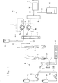
- a clamping device is applied to a blood glucose controlling device as illustrated in Fig. 1 .
- the blood glucose controlling device includes a dilution device A, a blood-sugar-level-measurement device S, and a transfusion device B.
- the dilution device A dilutes blood of a patient with a predetermined diluent.
- the diluted blood is sent to the blood-sugar-level-measurement device S through a flow route L3, and the transfusion device B can transfuse the diluted blood into the patient in accordance with the blood sugar level measured by the blood-sugar-level-measurement device S.
- the dilution device A includes a flow route L1 that is connected at one end thereof to a storage bag B1 that stores the diluent and at the other end thereof to an invasive catheter H.
- the flow route L1 is connected to a squeezable portion C1 at a halfway positon thereof.
- the dilution device A according to the present embodiment further includes a flow route L2 that is connected at one end thereof to the invasive catheter H and at the other end thereof to a mixing unit N such as a chamber.
- the flow route L1 and the flow route L2 are each a flexible tube in which liquid is allowed to flow.
- a liquid-exhaustion detector f is provided over halfway positions of the flow routes L1 and L2, so that liquid exhaustion can be detected.
- the invasive catheter H is connected to both the other end of the flow route L1 and the one end of the flow route L2 and is indwelling into the patient.
- the invasive catheter H collects the blood of the patient while allowing the diluent in the storage bag B1 to be introduced thereinto, thereby being capable of supplying the blood mixed with the diluent to the mixing unit N.
- the mixing unit N is connected to the blood-sugar-level-measurement device S.
- the diluted liquid substantially evenly mixed in the mixing unit N is supplied to the blood-sugar-level-measurement device S through the flow route L3.
- the squeezable portion C1 of the flexible tube forming the flow route L1 and a squeezable portion C2 of the flexible tube forming the flow route L2 are attached to the peristaltic pump 1 according to the present embodiment.
- the peristaltic pump 1 is capable of allowing the diluent and the blood to flow simultaneously at a predetermined ratio.
- the peristaltic pump 1 includes a first rotor 2a, a second rotor 2b, rollers 3a provided to the first rotor 2a, and rollers 3b provided to the second rotor 2b.
- a motor which is not illustrated, is activated, the first rotor 2a and the second rotor 2b are simultaneously rotated. Accordingly, the rollers 3a of the first rotor 2a squeeze the squeezable portion C1, and the rollers 3b of the second rotor 2b squeeze the squeezable portion C2.
- the blood-sugar-level-measurement device S includes glucose sensor Sa.
- the glucose sensor Sa is capable of, for example, decomposing grape sugar while continuously introducing the diluted liquid supplied from the dilution device A onto an enzyme film and thus measuring the blood sugar level from the value of a current generated at the decomposition.
- the blood-sugar-level-measurement device S is connected to a drainage bag B2 with a flow route L4.
- the blood collected from the patient is diluted with the diluent at a predetermined ratio, is subjected to the measurement of the blood sugar level by the glucose sensor Sa of the blood-sugar-level-measurement device S, and is discharged into the drainage bag B2.
- the transfusion device B can lower the blood sugar level by injecting insulin into the patient. If the blood sugar level is too low, the transfusion device B can raise the blood sugar level by injecting grape sugar (glucose) into the patient.
- the transfusion device B includes a storage bag B3 that stores insulin, a storage bag B4 that stores glucose, a transfusion line L5 for injecting liquid into the patient, and a clamping device 4.
- the transfusion line L5 is connected to a puncture needle I at one end thereof and to branch lines (L5a and L5b) at the other end thereof.
- the branch line L5a is connected to the storage bag B3, and the branch line L5b is connected to the storage bag B4.
- the branch line L5a is provided with a peristaltic pump P1.
- the peristaltic pump P1 When the peristaltic pump P1 is activated, the insulin in the storage bag B3 can be made to flow through the transfusion line L5.
- the branch line L5b is provided with a peristaltic pump P2.
- the peristaltic pump P2 When the peristaltic pump P2 is activated, the glucose in the storage bag B4 can be made to flow through the transfusion line L5.
- the peristaltic pump P1 is activated so that the insulin can be injected into the patient through the puncture needle I. If the blood sugar level measured by the blood-sugar-level-measurement device S is too low, the peristaltic pump P2 is activated so that the glucose can be injected into the patient through the puncture needle I.
- the clamping device 4 is attached to a side face of the body of the blood glucose controlling device and includes, as illustrated in Figs. 1 and 2 , a holding member 7 that is capable of holding a flexible tube (in the present embodiment, the flexible tube forming the transfusion line L5) in which a fluid is allowed to flow, a clamping member 8 that is capable of clamping and thus closing a clamping portion of the flexible tube held by the holding member 7 as intended, a bubble-detecting device 11, a heating device 12, and a temperature-detecting device 13.
- the flexible tube or the like forming the transfusion line L5 is preferably made of PVC (polyvinyl chloride) or the like that is resistant to sterilization.
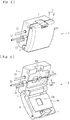
- the holding member 7 forms the housing of the clamping device 4. As illustrated in Figs. 3 to 7 , the holding member 7 includes a body portion 5 that holds the flexible tube (the transfusion line L5) and to which the clamping member 8 is attached, and a lid portion 6 that is attached to the body portion 5 and that can cover and nip a clamping portion L5c of the flexible tube (the transfusion line L5) that is held by the body portion 5.
- the lid portion 6 is openable and closable by swinging about a swing shaft n, and is lockable when a lock r catches the body portion 5.
- the body portion 5 (specifically, a nipping part 5a of the body portion 5) according to the present embodiment has a fitting groove m in which the flexible tube (the transfusion line L5) is fittable in the lengthwise direction thereof.
- the fitting groove m is a U-shaped groove that conforms to the outer peripheral surface of the flexible tube forming the transfusion line L5.
- a part including the clamping portion L5c is fitted into the fitting groove m, whereby the flexible tube can be positioned and be held therein.
- the fitting groove m according to the present embodiment is provided in the body portion 5.
- the fitting groove m may be provided in the lid portion 6 (for example, in a nipping part 6a of the lid portion 6).
- the nipping part 5a of the body portion 5 and the nipping part 6a of the lid portion 6 meet each other, whereby the flexible tube (the transfusion line L5) fitted in the fitting groove m can be nipped therebetween.
- the nipping part 5a of the body portion 5 is made of a material, such as an aluminum material, having an excellent heat-transmission characteristic and can facilitate the efficient heating of the clamping portion L5c by the heating device 12 to be described below.
- the other part around the nipping part 5a is made of a heat-insulating material.
- reference numeral 5aa denotes a through hole in which a rod 9 included in the clamping member 8 is movable back and forth
- reference numeral 5ab denotes a through hole through which an infrared-ray-emitting element 11a and an infrared-ray-receiving element 11b of the bubble-detecting device 11 face each other.
- the clamping member 8 includes a light-blocking plate 15 that is movable along with the rod 9, and a photoelectric element 14 including an element on the light-emitting side that emits light and an element on the light-receiving side that receives the light.
- a light-blocking plate 15 that is movable along with the rod 9, and a photoelectric element 14 including an element on the light-emitting side that emits light and an element on the light-receiving side that receives the light.
- the bubble-detecting device 11 is a sensor that is capable of detecting bubbles (air) in the liquid flowing in the transfusion line L5.
- the bubble-detecting device 11 includes, for example, the infrared-ray-emitting element 11a formed of a piezoelectric element, and the infrared-ray-receiving element 11b formed of a piezoelectric element.
- the infrared-ray-emitting element 11a formed of a piezoelectric element
- the infrared-ray-receiving element 11b formed of a piezoelectric element.
- the infrared-ray-emitting element 11a and the infrared-ray-receiving element 11b are arranged face to face at one edge and the other edge, respectively, of the fitting groove m provided in the body portion 5, so that infrared rays can pass through the flexible tube forming the transfusion line L5 fitted in the fitting groove m.
- the infrared-ray-emitting element 11a is capable of applying infrared rays toward the flexible tube forming the transfusion line L5 fitted in the fitting groove m, and the infrared-ray-receiving element 11b is capable of receiving the oscillation.
- the infrared-ray-receiving element 11b is configured such that the voltage thereof changes in accordance with the quantity of light received. If the detected voltage exceeds a predetermined threshold, it is detected that the liquid (insulin or glucose) flowing in the transfusion line L5 contains bubbles. The quantity of light is smaller in the case of bubbles (because of a lens effect) than in the case of the liquid such as insulin or glucose. Therefore, if the voltage detected by the infrared-ray-receiving element 11b becomes lower than the predetermined threshold, it is regarded that bubbles are detected.
- the clamping member 8 can clamp and close the clamping portion L5c of the flexible tube forming the transfusion line L5. Hence, during a transfusion process in which insulin, glucose, or the like is injected into the patient, bubbles contained in the liquid can be prevented from being injected into the body of the patient.
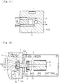
- the heating device 12 is a heater or the like including a coil that is capable of generating heat when energized or a heating mechanism equivalent thereto. As illustrated in Fig. 8, the heating device 12 is provided in the nipping part 5a of the body portion 5 and is capable of heating the clamping portion L5c of the flexible tube. That is, when the heating device 12 is energized and generates heat, the heat is transmitted through the nipping part 5a that is made of an aluminum material and can heat the clamping portion L5c of the flexible tube fitted in the fitting groove m.
- the temperature-detecting device 13 is a sensor that is capable of detecting the temperature resulting from the heating by the heating device 12 (in the present embodiment, the temperature of the nipping part 5a). As illustrated in Fig. 1 , the temperature-detecting device 13 is connected to a control device 16.
- the control device 16 is a microcomputer or the like that is connected to the heating device 12 and to the temperature-detecting device 13.
- the control device 16 is capable of controlling the heating by the heating device 12 in accordance with the temperature detected by the temperature-detecting device 13. Under such control, the clamping portion L5c of the flexible tube can be kept at a predetermined temperature (for example, a temperature +/-1°C of a target temperature).
- the present embodiment employs the heating device 12 that is capable of heating the clamping portion L5c of the flexible tube forming the transfusion line L5.
- the flexible tube can always be clamped in a good manner and can assuredly be closed without a large clamping force. That is, since the clamping portion L5c is heated, the temperature dependency of the flexible tube (particularly, PVC) with respect to the flexibility can be eliminated. Hence, the clamping portion L5c can always be clamped in a good manner.
- the present embodiment further employs the temperature-detecting device 13 that is capable of detecting the temperature resulting from the heating by the heating device 12. Since the heating by the heating device 12 is controlled in accordance with the temperature detected by the temperature-detecting device 13, the clamping portion L5c of the flexible tube can be kept at a predetermined temperature. Hence, the clamping portion L5c of the flexible tube can be prevented from being heated excessively and becoming unable to fully restore its original shape after being clamped.
- the holding member 7 includes the body portion 5 that holds the flexible tube and that is provided with the clamping member 8, the lid portion 6 provided to the body portion 5 and that is capable of covering and nipping the clamping portion L5c of the flexible tube held by the body portion 5, and the fitting groove m provided in the body portion 5 and in which the flexible tube is fittable in the lengthwise direction. Furthermore, the heating device 12 is attached to the body portion 5, in which the fitting groove m is provided. Hence, the heating of the clamping portion L5c by the heating device 12 can be performed efficiently.
- the fitting groove m may be provided in the lid portion 6 (for example, the nipping part 6a of the lid portion 6). In that case, the heating device 12 and the temperature-detecting device 13 are preferably attached to the lid portion 6 provided with the fitting groove m.
- the flexible tube forms the transfusion line L5 through which liquid is injected into the patient.
- the holding member 7 includes the bubble-detecting device 11 that is capable of detecting bubbles contained in the liquid flowing in the flexible tube. Furthermore, if any bubbles are detected by the bubble-detecting device 11, the clamping member 8 can clamp and close the clamping portion L5c of the flexible tube. Hence, if any bubbles are contained in the liquid injected into the patient, the clamping portion L5c can be closed assuredly and promptly. Thus, such bubbles can more assuredly be prevented from reaching the patient.
- the heating device 12 as a heater may be replaced with a heating device including a fan that blows warm air, a Peltier element, or the like.
- the body portion 5 may be made of a material having a low heat-transmission characteristic but may include a member having a high heat-transmission characteristic and the heating device 12 in the body portion 5.
- the clamping portion L5c may be heated only with the heating device 12 without providing the temperature-detecting device 13, or the flexible tube may be clamped simply without providing the bubble-detecting device 11.
- the present invention may be applied to a device that is provided to an extracorporeal circulation circuit such as a blood circuit included in a blood purification apparatus used in dialysis treatment or the like.
- the bubble-detecting device 11 is not limited to a device based on infrared rays as in the above embodiment and may be based on ultrasonic waves.
- the present invention is also applicable to another device having any other external shape or any other additional functions, as long as the clamping device includes a heating device that is capable of heating a clamping portion of a flexible tube.
Landscapes
- Health & Medical Sciences (AREA)
- Heart & Thoracic Surgery (AREA)
- Animal Behavior & Ethology (AREA)
- General Health & Medical Sciences (AREA)
- Biomedical Technology (AREA)
- Engineering & Computer Science (AREA)
- Hematology (AREA)
- Life Sciences & Earth Sciences (AREA)
- Veterinary Medicine (AREA)
- Anesthesiology (AREA)
- Public Health (AREA)
- Vascular Medicine (AREA)
- Pulmonology (AREA)
- Cardiology (AREA)
- Infusion, Injection, And Reservoir Apparatuses (AREA)
- External Artificial Organs (AREA)
Abstract
Description
- The present invention relates to a clamping device including a holding member that is capable of holding a flexible tube in which a fluid is allowed to flow, and a clamping member that is capable of closing, as intended, a predetermined part of the flexible tube, which is held by the holding member, by pressing the predetermined part.
- There is a proposal of a blood glucose controlling device (see
PTL 1, for example) in which while blood is collected from the body of a patient, the blood is diluted with a predetermined diluent and the blood sugar level of the blood is measured in real time with a blood-sugar-level-measurement device such as a glucose sensor. If the measured blood sugar level is too high, insulin is injected into the patient so that the blood sugar level can be lowered. If the measured blood sugar level is too low, grape sugar (glucose) is injected into the patient so that the blood sugar level can be raised. - Such a blood glucose controlling device includes an injection line formed of a flexible tube through which either the insulin or the glucose can be injected into the patient. Furthermore, the blood glucose controlling device is provided with a bubble-detecting device that is capable of detecting bubbles contained in the liquid flowing in the injection line, and a clamping device including a clamping member that is capable of clamping and closing the injection line if any bubbles are detected by the bubble-detecting device. Hence, if the liquid contains any bubbles in the process of injecting the insulin or the glucose into the patient, the injection line is closed and the bubbles can be prevented from reaching the body of the patient.
- PTL 1: Japanese Unexamined Patent Application Publication No.
2013-245664 - In the clamping device according to the above known technique, however, if the temperature of the clamping portion of the flexible tube is low, good clamping with the clamping member may be hampered. That is, if the temperature is low, the flexible tube, which is typically made of resin such as PVC, becomes less elastic. Consequently, even if the clamping portion is clamped with the clamping member, the flexible tube might not deform satisfactorily and might not be closed. If a clamping device capable of generating a large clamping force is used, a certain level of clamping force can be obtained regardless of the temperature of the flexible tube. In that case, however, a clamping member that consumes high power needs to be used, leading to a problem that the heat generated at the activation may affect the capability of distinguishing bubbles from liquid in the clamping portion.
- The present invention has been conceived in view of such circumstances and provides a clamping device that is always capable of clamping a flexible tube in a good manner without a large clamping force and assuredly closing the flexible tube.
- According to the invention of
Claim 1, there is provided a clamping device including a holding member that is capable of holding a flexible tube in which a fluid is allowed to flow, and a clamping member that is capable of clamping and closing, as intended, a clamping portion of the flexible tube that is held by the holding member. The clamping device further includes a heating device that is capable of heating the clamping portion of the flexible tube. - According to the invention of Claim 2, the clamping device according to
Claim 1 further includes a temperature-detecting device that is capable of detecting a temperature resulting from the heating by the heating device. It is possible to keep the clamping portion of the flexible tube at a predetermined temperature by controlling, in accordance with the temperature detected by the temperature-detecting device, the heating by the heating device. - According to the invention of Claim 3, in the clamping device according to
Claim 1 or 2, the holding member includes a body portion that holds the flexible tube and that is provided with the clamping member, a lid portion provided to the body portion and that is capable of covering and nipping the clamping portion of the flexible tube held by the body portion, and a fitting groove provided in the body portion or the lid portion and in which the flexible tube is fittable in a lengthwise direction. The heating device is provided to the body portion or the lid portion that is provided with the fitting groove. - According to the invention of
Claim 4, in the clamping device according to any ofClaims 1 to 3, the flexible tube forms a transfusion line through which liquid is injected into a patient, the holding member is provided with a bubble-detecting device that is capable of detecting bubbles contained in the liquid flowing in the flexible tube, and the clamping member is capable of clamping and closing the clamping portion of the flexible tube under a condition that any bubbles are detected by the bubble-detecting device. - According to the invention of
Claim 1, the clamping device includes the heating device that is capable of heating the clamping portion of the flexible tube. Hence, the flexible tube can always be clamped in a good manner and can assuredly be closed without a large clamping force. - According to the invention of Claim 2, the clamping device includes the temperature-detecting device that is capable of detecting the temperature resulting from the heating by the heating device. It is possible to keep the clamping portion of the flexible tube at a predetermined temperature by controlling, in accordance with the temperature detected by the temperature-detecting device, the heating by the heating device. Hence, the clamping portion of the flexible tube can be prevented from being heated excessively and becoming unable to fully restore its original shape after being clamped.
- According to the invention of Claim 3, the holding member includes the body portion that holds the flexible tube and that is provided with the clamping member, the lid portion provided to the body portion and that is capable of covering and nipping the clamping portion of the flexible tube held by the body portion, and the fitting groove provided in the body portion or the lid portion and in which the flexible tube is fittable in the lengthwise direction. Furthermore, the heating device is provided to the body portion or the lid portion that is provided with the fitting groove. Hence, the heating of the clamping portion by the heating device can be performed efficiently.
- According to the invention of
Claim 4, the flexible tube forms the transfusion line through which the liquid is injected into the patient, the holding member is provided with the bubble-detecting device that is capable of detecting bubbles contained in the liquid flowing in the flexible tube, and the clamping member is capable of clamping and closing the clamping portion of the flexible tube under a condition that any bubbles are detected by the bubble-detecting device. Hence, if any bubbles are contained in the liquid injected into the patient, the clamping portion can be closed assuredly and promptly. Thus, such bubbles can more assuredly be prevented from reaching the patient. -
- [
Fig. 1] Fig. 1 is a schematic diagram of a blood glucose controlling device to which a clamping device according to an embodiment of the present invention is applied. - [
Fig. 2] Fig. 2 is an external view of the blood glucose controlling device. - [
Fig. 3] Fig. 3 is a perspective external view of the clamping device (with a lid portion thereof closed) according to the embodiment. - [
Fig. 4] Fig. 4 is another perspective external view of the clamping device (with the lid portion open). - [
Fig. 5] Fig. 5 is a third-angle projection of the clamping device. - [
Fig. 6] Fig. 6 is a longitudinal sectional view (along line VI-VI illustrated inFig. 5 ) of the clamping device (before clamping). - [
Fig. 7] Fig. 7 is another longitudinal sectional view of the clamping device (during clamping). - [Fig. 8] Fig. 8 is a sectional view along line VIII-VIII illustrated in
Fig. 5 . - [
Fig. 9] Fig. 9 is a sectional view along line IX-IX illustrated inFig. 5 . - An embodiment of the present invention will now be described specifically with reference to the drawings.
- A clamping device according to the present embodiment is applied to a blood glucose controlling device as illustrated in
Fig. 1 . The blood glucose controlling device includes a dilution device A, a blood-sugar-level-measurement device S, and a transfusion device B. The dilution device A dilutes blood of a patient with a predetermined diluent. The diluted blood is sent to the blood-sugar-level-measurement device S through a flow route L3, and the transfusion device B can transfuse the diluted blood into the patient in accordance with the blood sugar level measured by the blood-sugar-level-measurement device S. - The dilution device A according to the present embodiment includes a flow route L1 that is connected at one end thereof to a storage bag B1 that stores the diluent and at the other end thereof to an invasive catheter H. The flow route L1 is connected to a squeezable portion C1 at a halfway positon thereof. The dilution device A according to the present embodiment further includes a flow route L2 that is connected at one end thereof to the invasive catheter H and at the other end thereof to a mixing unit N such as a chamber. The flow route L1 and the flow route L2 are each a flexible tube in which liquid is allowed to flow. A liquid-exhaustion detector f is provided over halfway positions of the flow routes L1 and L2, so that liquid exhaustion can be detected.
- The invasive catheter H is connected to both the other end of the flow route L1 and the one end of the flow route L2 and is indwelling into the patient. The invasive catheter H collects the blood of the patient while allowing the diluent in the storage bag B1 to be introduced thereinto, thereby being capable of supplying the blood mixed with the diluent to the mixing unit N. The mixing unit N is connected to the blood-sugar-level-measurement device S. The diluted liquid substantially evenly mixed in the mixing unit N is supplied to the blood-sugar-level-measurement device S through the flow route L3.
- The squeezable portion C1 of the flexible tube forming the flow route L1 and a squeezable portion C2 of the flexible tube forming the flow route L2 are attached to the
peristaltic pump 1 according to the present embodiment. Theperistaltic pump 1 is capable of allowing the diluent and the blood to flow simultaneously at a predetermined ratio. Theperistaltic pump 1 includes afirst rotor 2a, asecond rotor 2b,rollers 3a provided to thefirst rotor 2a, androllers 3b provided to thesecond rotor 2b. When a motor, which is not illustrated, is activated, thefirst rotor 2a and thesecond rotor 2b are simultaneously rotated. Accordingly, therollers 3a of thefirst rotor 2a squeeze the squeezable portion C1, and therollers 3b of thesecond rotor 2b squeeze the squeezable portion C2. - The blood-sugar-level-measurement device S includes glucose sensor Sa. The glucose sensor Sa is capable of, for example, decomposing grape sugar while continuously introducing the diluted liquid supplied from the dilution device A onto an enzyme film and thus measuring the blood sugar level from the value of a current generated at the decomposition. The blood-sugar-level-measurement device S is connected to a drainage bag B2 with a flow route L4. Thus, the blood collected from the patient is diluted with the diluent at a predetermined ratio, is subjected to the measurement of the blood sugar level by the glucose sensor Sa of the blood-sugar-level-measurement device S, and is discharged into the drainage bag B2.
- If the blood sugar level measured by the blood-sugar-level-measurement device S is too high, the transfusion device B can lower the blood sugar level by injecting insulin into the patient. If the blood sugar level is too low, the transfusion device B can raise the blood sugar level by injecting grape sugar (glucose) into the patient. The transfusion device B includes a storage bag B3 that stores insulin, a storage bag B4 that stores glucose, a transfusion line L5 for injecting liquid into the patient, and a
clamping device 4. - The transfusion line L5 is connected to a puncture needle I at one end thereof and to branch lines (L5a and L5b) at the other end thereof. The branch line L5a is connected to the storage bag B3, and the branch line L5b is connected to the storage bag B4. The branch line L5a is provided with a peristaltic pump P1. When the peristaltic pump P1 is activated, the insulin in the storage bag B3 can be made to flow through the transfusion line L5. The branch line L5b is provided with a peristaltic pump P2. When the peristaltic pump P2 is activated, the glucose in the storage bag B4 can be made to flow through the transfusion line L5.
- In a state where the puncture needle I is stuck in the patient, if the blood sugar level measured by the blood-sugar-level-measurement device S is too high, the peristaltic pump P1 is activated so that the insulin can be injected into the patient through the puncture needle I. If the blood sugar level measured by the blood-sugar-level-measurement device S is too low, the peristaltic pump P2 is activated so that the glucose can be injected into the patient through the puncture needle I.
- As illustrated in
Fig. 2 , theclamping device 4 according to the present embodiment is attached to a side face of the body of the blood glucose controlling device and includes, as illustrated inFigs. 1 and2 , a holdingmember 7 that is capable of holding a flexible tube (in the present embodiment, the flexible tube forming the transfusion line L5) in which a fluid is allowed to flow, a clampingmember 8 that is capable of clamping and thus closing a clamping portion of the flexible tube held by the holdingmember 7 as intended, a bubble-detectingdevice 11, aheating device 12, and a temperature-detectingdevice 13. The flexible tube or the like forming the transfusion line L5 is preferably made of PVC (polyvinyl chloride) or the like that is resistant to sterilization. - The holding
member 7 forms the housing of theclamping device 4. As illustrated inFigs. 3 to 7 , the holdingmember 7 includes abody portion 5 that holds the flexible tube (the transfusion line L5) and to which the clampingmember 8 is attached, and alid portion 6 that is attached to thebody portion 5 and that can cover and nip a clamping portion L5c of the flexible tube (the transfusion line L5) that is held by thebody portion 5. Thelid portion 6 is openable and closable by swinging about a swing shaft n, and is lockable when a lock r catches thebody portion 5. - The body portion 5 (specifically, a nipping
part 5a of the body portion 5) according to the present embodiment has a fitting groove m in which the flexible tube (the transfusion line L5) is fittable in the lengthwise direction thereof. Specifically, the fitting groove m is a U-shaped groove that conforms to the outer peripheral surface of the flexible tube forming the transfusion line L5. A part including the clamping portion L5c is fitted into the fitting groove m, whereby the flexible tube can be positioned and be held therein. The fitting groove m according to the present embodiment is provided in thebody portion 5. Alternatively, the fitting groove m may be provided in the lid portion 6 (for example, in anipping part 6a of the lid portion 6). - When the
lid portion 6 is closed, the nippingpart 5a of thebody portion 5 and the nippingpart 6a of thelid portion 6 meet each other, whereby the flexible tube (the transfusion line L5) fitted in the fitting groove m can be nipped therebetween. The nippingpart 5a of thebody portion 5 is made of a material, such as an aluminum material, having an excellent heat-transmission characteristic and can facilitate the efficient heating of the clamping portion L5c by theheating device 12 to be described below. The other part around the nippingpart 5a is made of a heat-insulating material. In the drawings, reference numeral 5aa denotes a through hole in which arod 9 included in the clampingmember 8 is movable back and forth, and reference numeral 5ab denotes a through hole through which an infrared-ray-emittingelement 11a and an infrared-ray-receivingelement 11b of the bubble-detectingdevice 11 face each other. - The clamping
member 8 is capable of clamping and thus closing, as intended, the clamping portion L5c of the flexible tube (the transfusion line L5) held by the holding member 7 (the body portion 5). The clampingmember 8 includes therod 9 and asolenoid 10. When thesolenoid 10 is energized, therod 9 that has been in an unclamping state (seeFig. 6 ) moves toward the flexible tube and falls into a clamping state (seeFig. 7 ). Accordingly, the tip of therod 9 presses and deforms the clamping portion L5c, whereby the flow route is closed. When the energization of thesolenoid 10 is stopped, therod 9 that has been in the clamping state moves toward the other side and returns to the unclamping state. Accordingly, the clamping portion L5c restores its original shape, and the flow route is opened. - The clamping
member 8 according to the present embodiment includes a light-blockingplate 15 that is movable along with therod 9, and aphotoelectric element 14 including an element on the light-emitting side that emits light and an element on the light-receiving side that receives the light. When therod 9 is in the unclamping state, the light from the light-emitting side of thephotoelectric element 14 can be received by the light-receiving side. When therod 9 is in the clamping state, the light from the light-emitting side of thephotoelectric element 14 is blocked by the light-blockingplate 15. Therefore, if whether or not the light is received by the element on the light-receiving side of thephotoelectric element 14 is detected, whether therod 9 is in the clamping state or in the unclamping state can be identified. - The bubble-detecting
device 11 is a sensor that is capable of detecting bubbles (air) in the liquid flowing in the transfusion line L5. As illustrated inFigs. 6, 7 , and9 , the bubble-detectingdevice 11 includes, for example, the infrared-ray-emittingelement 11a formed of a piezoelectric element, and the infrared-ray-receivingelement 11b formed of a piezoelectric element. As illustrated inFig. 9 , the infrared-ray-emittingelement 11a and the infrared-ray-receivingelement 11b are arranged face to face at one edge and the other edge, respectively, of the fitting groove m provided in thebody portion 5, so that infrared rays can pass through the flexible tube forming the transfusion line L5 fitted in the fitting groove m. - The infrared-ray-emitting
element 11a is capable of applying infrared rays toward the flexible tube forming the transfusion line L5 fitted in the fitting groove m, and the infrared-ray-receivingelement 11b is capable of receiving the oscillation. The infrared-ray-receivingelement 11b is configured such that the voltage thereof changes in accordance with the quantity of light received. If the detected voltage exceeds a predetermined threshold, it is detected that the liquid (insulin or glucose) flowing in the transfusion line L5 contains bubbles. The quantity of light is smaller in the case of bubbles (because of a lens effect) than in the case of the liquid such as insulin or glucose. Therefore, if the voltage detected by the infrared-ray-receivingelement 11b becomes lower than the predetermined threshold, it is regarded that bubbles are detected. - Thus, in the present embodiment, if any bubbles are detected by the bubble-detecting
device 11, the clampingmember 8 can clamp and close the clamping portion L5c of the flexible tube forming the transfusion line L5. Hence, during a transfusion process in which insulin, glucose, or the like is injected into the patient, bubbles contained in the liquid can be prevented from being injected into the body of the patient. - The
heating device 12 is a heater or the like including a coil that is capable of generating heat when energized or a heating mechanism equivalent thereto. As illustrated in Fig. 8, theheating device 12 is provided in the nippingpart 5a of thebody portion 5 and is capable of heating the clamping portion L5c of the flexible tube. That is, when theheating device 12 is energized and generates heat, the heat is transmitted through the nippingpart 5a that is made of an aluminum material and can heat the clamping portion L5c of the flexible tube fitted in the fitting groove m. - The temperature-detecting
device 13 is a sensor that is capable of detecting the temperature resulting from the heating by the heating device 12 (in the present embodiment, the temperature of the nippingpart 5a). As illustrated inFig. 1 , the temperature-detectingdevice 13 is connected to acontrol device 16. Thecontrol device 16 is a microcomputer or the like that is connected to theheating device 12 and to the temperature-detectingdevice 13. Thecontrol device 16 is capable of controlling the heating by theheating device 12 in accordance with the temperature detected by the temperature-detectingdevice 13. Under such control, the clamping portion L5c of the flexible tube can be kept at a predetermined temperature (for example, a temperature +/-1°C of a target temperature). - The present embodiment employs the
heating device 12 that is capable of heating the clamping portion L5c of the flexible tube forming the transfusion line L5. Hence, the flexible tube can always be clamped in a good manner and can assuredly be closed without a large clamping force. That is, since the clamping portion L5c is heated, the temperature dependency of the flexible tube (particularly, PVC) with respect to the flexibility can be eliminated. Hence, the clamping portion L5c can always be clamped in a good manner. - The present embodiment further employs the temperature-detecting
device 13 that is capable of detecting the temperature resulting from the heating by theheating device 12. Since the heating by theheating device 12 is controlled in accordance with the temperature detected by the temperature-detectingdevice 13, the clamping portion L5c of the flexible tube can be kept at a predetermined temperature. Hence, the clamping portion L5c of the flexible tube can be prevented from being heated excessively and becoming unable to fully restore its original shape after being clamped. - The holding
member 7 includes thebody portion 5 that holds the flexible tube and that is provided with the clampingmember 8, thelid portion 6 provided to thebody portion 5 and that is capable of covering and nipping the clamping portion L5c of the flexible tube held by thebody portion 5, and the fitting groove m provided in thebody portion 5 and in which the flexible tube is fittable in the lengthwise direction. Furthermore, theheating device 12 is attached to thebody portion 5, in which the fitting groove m is provided. Hence, the heating of the clamping portion L5c by theheating device 12 can be performed efficiently. Note that the fitting groove m may be provided in the lid portion 6 (for example, the nippingpart 6a of the lid portion 6). In that case, theheating device 12 and the temperature-detectingdevice 13 are preferably attached to thelid portion 6 provided with the fitting groove m. - The flexible tube forms the transfusion line L5 through which liquid is injected into the patient. On the other hand, the holding
member 7 includes the bubble-detectingdevice 11 that is capable of detecting bubbles contained in the liquid flowing in the flexible tube. Furthermore, if any bubbles are detected by the bubble-detectingdevice 11, the clampingmember 8 can clamp and close the clamping portion L5c of the flexible tube. Hence, if any bubbles are contained in the liquid injected into the patient, the clamping portion L5c can be closed assuredly and promptly. Thus, such bubbles can more assuredly be prevented from reaching the patient. - While an embodiment has been described above, the present invention is not limited thereto. For example, the
heating device 12 as a heater may be replaced with a heating device including a fan that blows warm air, a Peltier element, or the like. Alternatively, thebody portion 5 may be made of a material having a low heat-transmission characteristic but may include a member having a high heat-transmission characteristic and theheating device 12 in thebody portion 5. As another alternative, the clamping portion L5c may be heated only with theheating device 12 without providing the temperature-detectingdevice 13, or the flexible tube may be clamped simply without providing the bubble-detectingdevice 11. Moreover, while the above embodiment is applied to the transfusion device B included in a blood glucose controlling device, the present invention may be applied to a device that is provided to an extracorporeal circulation circuit such as a blood circuit included in a blood purification apparatus used in dialysis treatment or the like. In addition, the bubble-detectingdevice 11 is not limited to a device based on infrared rays as in the above embodiment and may be based on ultrasonic waves. - The present invention is also applicable to another device having any other external shape or any other additional functions, as long as the clamping device includes a heating device that is capable of heating a clamping portion of a flexible tube.
-
- 1 peristaltic pump
- 2a first rotor
- 2b second rotor
- 3a, 3b roller
- 4 clamping device
- 5 body portion
- 6 lid portion
- 7 holding member
- 8 clamping member
- 9 rod
- 10 solenoid
- 11 bubble-detecting device
- 12 heating device
- 13 temperature-detecting device
- 14 photoelectric element
- 15 light-blocking plate
- 16 control device
- A dilution device
- S blood-sugar-level-measurement device
- B transfusion device
- L5 transfusion line
- L5c clamping portion
Claims (4)
- A clamping device comprising:a holding member that is capable of holding a flexible tube in which a fluid is allowed to flow; anda clamping member that is capable of clamping and closing, as intended, a clamping portion of the flexible tube that is held by the holding member,wherein the clamping device further includes a heating device that is capable of heating the clamping portion of the flexible tube.
- The clamping device according to Claim 1, further comprising a temperature-detecting device that is capable of detecting a temperature resulting from the heating by the heating device, wherein it is possible to keep the clamping portion of the flexible tube at a predetermined temperature by controlling, in accordance with the temperature detected by the temperature-detecting device, the heating by the heating device.
- The clamping device according to Claim 1 or 2, wherein the holding member includesa body portion that holds the flexible tube and that is provided with the clamping member;a lid portion provided to the body portion and that is capable of covering and nipping the clamping portion of the flexible tube held by the body portion; anda fitting groove provided in the body portion or the lid portion and in which the flexible tube is fittable in a lengthwise direction, andwherein the heating device is provided to the body portion or the lid portion that is provided with the fitting groove.
- The clamping device according to any of Claims 1 to 3, wherein the flexible tube forms a transfusion line through which liquid is injected into a patient, the holding member is provided with a bubble-detecting device that is capable of detecting bubbles contained in the liquid flowing in the flexible tube, and the clamping member is capable of clamping and closing the clamping portion of the flexible tube under a condition that any bubbles are detected by the bubble-detecting device.
Applications Claiming Priority (2)
| Application Number | Priority Date | Filing Date | Title |
|---|---|---|---|
| JP2015249889A JP6706914B2 (en) | 2015-12-22 | 2015-12-22 | Clamp device |
| PCT/JP2016/088477 WO2017111077A1 (en) | 2015-12-22 | 2016-12-22 | Clamp device |
Publications (2)
| Publication Number | Publication Date |
|---|---|
| EP3384956A1 true EP3384956A1 (en) | 2018-10-10 |
| EP3384956A4 EP3384956A4 (en) | 2019-08-14 |
Family
ID=59090471
Family Applications (1)
| Application Number | Title | Priority Date | Filing Date |
|---|---|---|---|
| EP16878963.4A Withdrawn EP3384956A4 (en) | 2015-12-22 | 2016-12-22 | CLAMPING DEVICE |
Country Status (5)
| Country | Link |
|---|---|
| US (1) | US11013903B2 (en) |
| EP (1) | EP3384956A4 (en) |
| JP (1) | JP6706914B2 (en) |
| CN (1) | CN108472480A (en) |
| WO (1) | WO2017111077A1 (en) |
Families Citing this family (6)
| Publication number | Priority date | Publication date | Assignee | Title |
|---|---|---|---|---|
| US12083290B2 (en) * | 2019-04-08 | 2024-09-10 | Becton, Dickinson And Company | Catheter assembly clamp having an acoustic sensor |
| WO2021090531A1 (en) * | 2019-11-05 | 2021-05-14 | テルモ株式会社 | Artificial pancreas |
| JP7576080B2 (en) * | 2020-03-11 | 2024-10-30 | テルモ株式会社 | Detection device and infusion pump |
| CN113350192B (en) * | 2021-06-24 | 2022-08-12 | 傅晓燕 | Nasogastric tube assembly with positioning function |
| JP7815724B2 (en) * | 2021-12-07 | 2026-02-18 | 株式会社ジェイ・エム・エス | Clamping device and infusion monitoring device |
| JP2024059306A (en) * | 2022-10-18 | 2024-05-01 | ニプロ株式会社 | BLOOD PURIFICATION APPARATUS AND METHOD FOR CONTROLLING BLOOD PURIFICATION APPARATUS |
Family Cites Families (71)
| Publication number | Priority date | Publication date | Assignee | Title |
|---|---|---|---|---|
| US350850A (en) | 1886-10-12 | tatum | ||
| US183107A (en) * | 1876-10-10 | Improvement in milk-safes | ||
| US3419245A (en) | 1965-11-29 | 1968-12-31 | Vargas Mfg Co | Tube clamp |
| US3698681A (en) | 1970-12-15 | 1972-10-17 | Illinois Tool Works | On-off clamp for i. v. systems |
| JPS4922246B1 (en) | 1971-02-27 | 1974-06-07 | ||
| US3822052A (en) | 1973-04-02 | 1974-07-02 | Illinois Tool Works | Shut off clamp |
| US4053135A (en) | 1976-09-20 | 1977-10-11 | Sigma Scientific Development, Inc. | Hose clamp |
| FR2379290A1 (en) * | 1977-02-03 | 1978-09-01 | Keczely Lajis | Air bubble detector for blood transfusion unit - with IR rays passed through catheter tube by air bubble to be picked up by detector which actuates alarm and cuts off blood supply |
| US4235412A (en) | 1978-10-30 | 1980-11-25 | Plastronics, Inc. | Tube clamping device |
| US4643389A (en) | 1984-12-27 | 1987-02-17 | American Hospital Supply Corporation | Tubing occlusion clip |
| US4589626A (en) | 1985-03-13 | 1986-05-20 | Bioresearch Inc. | Hose clamp |
| CH669117A5 (en) | 1985-06-24 | 1989-02-28 | Contempo Products | DEVICE FOR SEALING AND DISCONNECTING A HOSE, IN PARTICULAR A HOSE USED IN DIALYSIS OR INFUSION. |
| JPH024384A (en) | 1988-06-14 | 1990-01-09 | Terumo Corp | Clamp |
| JPH0373162A (en) | 1989-08-14 | 1991-03-28 | Terumo Corp | Connecting implement and remedial apparatus provided therewith and connecting and dissociating device therefor |
| DE4118732A1 (en) | 1991-06-07 | 1992-12-10 | Joka Kathetertechnik Gmbh | HOSE CLAMP FOR MEDICAL PURPOSES |
| US5238218A (en) | 1992-07-15 | 1993-08-24 | Mackal Glenn H | Tube clamp |
| DE9310226U1 (en) | 1993-07-09 | 1993-09-30 | Spang & Brands GmbH, 61381 Friedrichsdorf | Hose clamp |
| CN2239266Y (en) * | 1995-12-27 | 1996-11-06 | 朱辉 | Multifunctional infusion controller |
| US6091737A (en) | 1996-11-15 | 2000-07-18 | Multi-Tech Systems, Inc. | Remote communications server system |
| US5827238A (en) * | 1997-10-30 | 1998-10-27 | Microwave Medical Systems, Inc. | Roller clamp-connector assembly |
| US6789118B1 (en) | 1999-02-23 | 2004-09-07 | Alcatel | Multi-service network switch with policy based routing |
| JP2001025505A (en) * | 1999-07-14 | 2001-01-30 | Terumo Corp | Transfusion pump |
| JP2001353215A (en) | 2000-06-13 | 2001-12-25 | Nikkiso Co Ltd | Medical Flexible Tube Clamping Device |
| US6592558B2 (en) | 2000-12-28 | 2003-07-15 | Baxter International Inc. | Clamp device, method and system for exchanging a solution |
| JP2002210006A (en) | 2001-01-17 | 2002-07-30 | Jms Co Ltd | Tube opening and closing clamp |
| US6938122B2 (en) | 2001-01-23 | 2005-08-30 | Emc Corporation | Remote mirroring in a switched environment |
| US8262639B2 (en) | 2002-01-31 | 2012-09-11 | Fenwal, Inc. | Irreversible flow control clamp |
| JP2003235971A (en) | 2002-02-19 | 2003-08-26 | Jms Co Ltd | Tube opening and closing clamp |
| WO2003105942A1 (en) * | 2002-06-14 | 2003-12-24 | Margaret Pamela Richardson | Improvements in and relating to control of liquid flow into or out of a human or animal body |
| US20040089828A1 (en) | 2002-10-18 | 2004-05-13 | Werth Albert A. | Conduit clamp |
| JP4091873B2 (en) | 2003-04-17 | 2008-05-28 | 日機装株式会社 | Dialysis machine |
| JP4137727B2 (en) | 2003-07-07 | 2008-08-20 | 日機装株式会社 | Flexible tube clamping device |
| US7516211B1 (en) | 2003-08-05 | 2009-04-07 | Cisco Technology, Inc. | Methods and apparatus to configure a communication port |
| US20060048142A1 (en) | 2004-09-02 | 2006-03-02 | Roese John J | System and method for rapid response network policy implementation |
| US7995498B2 (en) | 2006-02-13 | 2011-08-09 | Cisco Technology, Inc. | Method and system for providing configuration of network elements through hierarchical inheritance |
| EP2007474B1 (en) | 2006-04-05 | 2018-12-05 | Noble House Group Pty. Ltd. | Non-reopening locking pinch clamp for tubing |
| US7686279B2 (en) | 2006-05-12 | 2010-03-30 | Caridianbct, Inc. | Non-reopenable clamp for tubing sets |
| WO2008008963A1 (en) | 2006-07-13 | 2008-01-17 | Parker-Hannifin Corporation | Valve with freeze-proof heated valve seat |
| US7898986B2 (en) | 2006-10-31 | 2011-03-01 | Hewlett-Packard Development Company, L.P. | Port configuration |
| CN101352589B (en) | 2007-06-21 | 2012-04-18 | 日本哈娜好医材株式会社 | Clamping device for an operation |
| FR2920513B1 (en) | 2007-09-04 | 2021-05-28 | Fresenius Vial | CLAMP FOR SOFT TUBING, PUMP EQUIPPED WITH MEANS FOR OPENING SUCH CLAMP AND INFUSION SET EQUIPPED WITH SUCH CLAMP. |
| EP3620191B1 (en) * | 2008-01-23 | 2023-12-13 | DEKA Products Limited Partnership | Fluid line autoconnect apparatus and methods for medical treatment system |
| US8325630B2 (en) | 2008-02-29 | 2012-12-04 | Cisco Technology, Inc. | Distributed spanning tree protocol on a multi chassis port channel |
| JP5154979B2 (en) | 2008-03-05 | 2013-02-27 | 京浜ハイフロー販売株式会社 | Medical sampling valve |
| WO2011035367A1 (en) | 2009-09-23 | 2011-03-31 | Sukhvinder Singh | A pinch clamp |
| EP2332611B1 (en) | 2009-12-10 | 2020-06-17 | Fenwal, Inc. | Irreversible flow control clamp for flexible tubes |
| US8380828B1 (en) | 2010-01-21 | 2013-02-19 | Adtran, Inc. | System and method for locating offending network device and maintaining network integrity |
| JP5416608B2 (en) | 2010-02-10 | 2014-02-12 | 株式会社バルダン | Multi-needle sewing machine with sequin supply device |
| JP2012075520A (en) | 2010-09-30 | 2012-04-19 | Nihon Covidien Kk | Tool for preventing incorrect operation of clamp |
| CN202143737U (en) * | 2010-12-30 | 2012-02-15 | 湖北仙明医疗器械有限公司 | Micro-control instrument for infusion dropping speed and heating |
| US8559335B2 (en) | 2011-01-07 | 2013-10-15 | Jeda Networks, Inc. | Methods for creating virtual links between fibre channel over ethernet nodes for converged network adapters |
| EP2676690B1 (en) | 2011-02-17 | 2021-07-28 | Nipro Corporation | Medical tube clamp |
| WO2012131428A1 (en) | 2011-03-28 | 2012-10-04 | Telefonaktiebolaget L M Ericsson (Publ) | Method, apparatus and computer program product for updating load balancer configuration data |
| JP5748280B2 (en) | 2011-09-09 | 2015-07-15 | 日機装株式会社 | Dialysate extraction device |
| EP2583716B1 (en) | 2011-10-18 | 2015-07-29 | B. Braun Melsungen AG | Infusion hose clamp for a infusionpump and method for use of the same |
| US9211381B2 (en) * | 2012-01-20 | 2015-12-15 | Medical Solutions, Inc. | Method and apparatus for controlling temperature of medical liquids |
| JP5989554B2 (en) | 2012-02-07 | 2016-09-07 | 川澄化学工業株式会社 | Clamp and medical device |
| JP6114258B2 (en) * | 2012-03-26 | 2017-04-12 | テルモ株式会社 | Infusion pump |
| JP5872965B2 (en) | 2012-05-29 | 2016-03-01 | 日機装株式会社 | Quantitative sampling device, biological component measuring device, and artificial pancreas device |
| US20130343379A1 (en) | 2012-06-21 | 2013-12-26 | Jonathan Stroud | Ethernet-based internal device management |
| US8929379B2 (en) | 2012-06-21 | 2015-01-06 | Breakingpoint Systems, Inc. | High-speed CLD-based internal packet routing |
| US9833606B2 (en) | 2012-09-07 | 2017-12-05 | Fenwal, Inc. | Non-reopenable flow control clamp |
| WO2014162376A1 (en) | 2013-04-01 | 2014-10-09 | テルモ株式会社 | Clamp |
| AU2014295910A1 (en) * | 2013-07-29 | 2016-02-04 | Resmed Limited | Heat and moisture exchanger for a patient interface |
| JP6527826B2 (en) * | 2014-02-07 | 2019-06-05 | テルモ株式会社 | Tube clamp for extracorporeal circulation device and extracorporeal circulation device |
| CN106659829B (en) | 2014-06-30 | 2020-03-03 | 日机装株式会社 | Clamping device for flexible pipe |
| EP3193975B1 (en) * | 2014-09-18 | 2022-07-06 | DEKA Products Limited Partnership | Apparatus and method for infusing fluid through a tube by appropriately heating the tube |
| JP6181286B2 (en) | 2015-02-03 | 2017-08-16 | 日機装株式会社 | Clamping device |
| JP6082433B2 (en) | 2015-06-22 | 2017-02-15 | 日機装株式会社 | Clamping device |
| IL242942A0 (en) * | 2015-12-03 | 2016-04-21 | Gershon Goldenberg | Thermal control of liquids for transcutaneous delivery |
| US10960123B2 (en) * | 2018-06-26 | 2021-03-30 | Fresenius Medical Care Holdings, Inc. | Peritoneal dialysis systems and related methods |
-
2015
- 2015-12-22 JP JP2015249889A patent/JP6706914B2/en active Active
-
2016
- 2016-12-22 EP EP16878963.4A patent/EP3384956A4/en not_active Withdrawn
- 2016-12-22 WO PCT/JP2016/088477 patent/WO2017111077A1/en not_active Ceased
- 2016-12-22 CN CN201680075260.2A patent/CN108472480A/en active Pending
-
2018
- 2018-06-18 US US16/011,003 patent/US11013903B2/en active Active
Also Published As
| Publication number | Publication date |
|---|---|
| WO2017111077A1 (en) | 2017-06-29 |
| US11013903B2 (en) | 2021-05-25 |
| JP2017113144A (en) | 2017-06-29 |
| EP3384956A4 (en) | 2019-08-14 |
| CN108472480A (en) | 2018-08-31 |
| JP6706914B2 (en) | 2020-06-10 |
| US20180369565A1 (en) | 2018-12-27 |
Similar Documents
| Publication | Publication Date | Title |
|---|---|---|
| US11013903B2 (en) | Clamping device | |
| US20200093417A1 (en) | Devices capable of fluid sample concentration for extended sensing of analytes | |
| US11123463B2 (en) | Blood purification apparatus | |
| US9192708B2 (en) | Dialysate extraction apparatus | |
| US10653827B2 (en) | Blood purification apparatus | |
| US9205247B2 (en) | Connection port and dialysis apparatus having connection port | |
| WO2009036105A3 (en) | Infusion therapy sensor system | |
| CN107847655B (en) | Blood purification device | |
| JP5468414B2 (en) | Brain cooling device and brain cooling device suitable for the same | |
| JP5714029B2 (en) | Dialysis machine | |
| US10610634B2 (en) | Blood purification apparatus | |
| US20250144278A1 (en) | Pump device, and peritoneal dialysis device, system and method | |
| EP3860676A1 (en) | Biological component collection system and circuit internal pressure acquisition method | |
| US10441702B2 (en) | Medical fluid temperature control | |
| US10314961B2 (en) | Dialysate-extracting apparatus | |
| US12465673B2 (en) | Syringe warmer | |
| CN109289105A (en) | Medical liquid thermostatic heating device, infusion equipment and formula milk preparation equipment | |
| EP3523040A1 (en) | Cartridge, analysis system and method for testing a sample | |
| EP4062975B1 (en) | Hydrogen addition device | |
| JP6867426B2 (en) | Hydrogenation equipment and sterilization method for hydrogenation equipment | |
| JP2005131077A (en) | Liquid transfer system | |
| CN213058348U (en) | Blood sampling inspection censorship box | |
| US12220516B2 (en) | Apparatus and method for taking a sample from a fluid-conducting system | |
| EP2925446A1 (en) | Cartridge for uptake and processing of a sample | |
| KR100704206B1 (en) | Biological Liquid Sampling Sealed Storage Tube and Tube Automatic Sealing Device |
Legal Events
| Date | Code | Title | Description |
|---|---|---|---|
| STAA | Information on the status of an ep patent application or granted ep patent |
Free format text: STATUS: THE INTERNATIONAL PUBLICATION HAS BEEN MADE |
|
| PUAI | Public reference made under article 153(3) epc to a published international application that has entered the european phase |
Free format text: ORIGINAL CODE: 0009012 |
|
| STAA | Information on the status of an ep patent application or granted ep patent |
Free format text: STATUS: REQUEST FOR EXAMINATION WAS MADE |
|
| 17P | Request for examination filed |
Effective date: 20180627 |
|
| AK | Designated contracting states |
Kind code of ref document: A1 Designated state(s): AL AT BE BG CH CY CZ DE DK EE ES FI FR GB GR HR HU IE IS IT LI LT LU LV MC MK MT NL NO PL PT RO RS SE SI SK SM TR |
|
| AX | Request for extension of the european patent |
Extension state: BA ME |
|
| DAV | Request for validation of the european patent (deleted) | ||
| DAX | Request for extension of the european patent (deleted) | ||
| A4 | Supplementary search report drawn up and despatched |
Effective date: 20190717 |
|
| RIC1 | Information provided on ipc code assigned before grant |
Ipc: A61M 25/09 20060101ALI20190711BHEP Ipc: A61M 25/00 20060101ALI20190711BHEP Ipc: A61M 39/28 20060101AFI20190711BHEP Ipc: A61M 5/44 20060101ALI20190711BHEP Ipc: A61M 5/168 20060101ALI20190711BHEP Ipc: A61M 1/36 20060101ALI20190711BHEP |
|
| STAA | Information on the status of an ep patent application or granted ep patent |
Free format text: STATUS: EXAMINATION IS IN PROGRESS |
|
| 17Q | First examination report despatched |
Effective date: 20210121 |
|
| P01 | Opt-out of the competence of the unified patent court (upc) registered |
Effective date: 20230523 |
|
| STAA | Information on the status of an ep patent application or granted ep patent |
Free format text: STATUS: THE APPLICATION IS DEEMED TO BE WITHDRAWN |
|
| 18D | Application deemed to be withdrawn |
Effective date: 20240702 |