EP3384943A1 - Auto-injector - Google Patents
Auto-injector Download PDFInfo
- Publication number
- EP3384943A1 EP3384943A1 EP18166451.7A EP18166451A EP3384943A1 EP 3384943 A1 EP3384943 A1 EP 3384943A1 EP 18166451 A EP18166451 A EP 18166451A EP 3384943 A1 EP3384943 A1 EP 3384943A1
- Authority
- EP
- European Patent Office
- Prior art keywords
- carrier
- auto
- injector
- distal
- chassis
- Prior art date
- Legal status (The legal status is an assumption and is not a legal conclusion. Google has not performed a legal analysis and makes no representation as to the accuracy of the status listed.)
- Ceased
Links
Images


Classifications
-
- A—HUMAN NECESSITIES
- A61—MEDICAL OR VETERINARY SCIENCE; HYGIENE
- A61M—DEVICES FOR INTRODUCING MEDIA INTO, OR ONTO, THE BODY; DEVICES FOR TRANSDUCING BODY MEDIA OR FOR TAKING MEDIA FROM THE BODY; DEVICES FOR PRODUCING OR ENDING SLEEP OR STUPOR
- A61M5/00—Devices for bringing media into the body in a subcutaneous, intra-vascular or intramuscular way; Accessories therefor, e.g. filling or cleaning devices, arm-rests
- A61M5/178—Syringes
- A61M5/31—Details
- A61M5/32—Needles; Details of needles pertaining to their connection with syringe or hub; Accessories for bringing the needle into, or holding the needle on, the body; Devices for protection of needles
- A61M5/3205—Apparatus for removing or disposing of used needles or syringes, e.g. containers; Means for protection against accidental injuries from used needles
- A61M5/321—Means for protection against accidental injuries by used needles
- A61M5/322—Retractable needles, i.e. disconnected from and withdrawn into the syringe barrel by the piston
- A61M5/3232—Semi-automatic needle retraction, i.e. in which triggering of the needle retraction requires a deliberate action by the user, e.g. manual release of spring-biased retraction means
-
- A—HUMAN NECESSITIES
- A61—MEDICAL OR VETERINARY SCIENCE; HYGIENE
- A61M—DEVICES FOR INTRODUCING MEDIA INTO, OR ONTO, THE BODY; DEVICES FOR TRANSDUCING BODY MEDIA OR FOR TAKING MEDIA FROM THE BODY; DEVICES FOR PRODUCING OR ENDING SLEEP OR STUPOR
- A61M5/00—Devices for bringing media into the body in a subcutaneous, intra-vascular or intramuscular way; Accessories therefor, e.g. filling or cleaning devices, arm-rests
- A61M5/178—Syringes
- A61M5/20—Automatic syringes, e.g. with automatically actuated piston rod, with automatic needle injection, filling automatically
- A61M5/2033—Spring-loaded one-shot injectors with or without automatic needle insertion
-
- A—HUMAN NECESSITIES
- A61—MEDICAL OR VETERINARY SCIENCE; HYGIENE
- A61M—DEVICES FOR INTRODUCING MEDIA INTO, OR ONTO, THE BODY; DEVICES FOR TRANSDUCING BODY MEDIA OR FOR TAKING MEDIA FROM THE BODY; DEVICES FOR PRODUCING OR ENDING SLEEP OR STUPOR
- A61M5/00—Devices for bringing media into the body in a subcutaneous, intra-vascular or intramuscular way; Accessories therefor, e.g. filling or cleaning devices, arm-rests
- A61M5/178—Syringes
- A61M5/20—Automatic syringes, e.g. with automatically actuated piston rod, with automatic needle injection, filling automatically
- A61M2005/2006—Having specific accessories
- A61M2005/2013—Having specific accessories triggering of discharging means by contact of injector with patient body
-
- A—HUMAN NECESSITIES
- A61—MEDICAL OR VETERINARY SCIENCE; HYGIENE
- A61M—DEVICES FOR INTRODUCING MEDIA INTO, OR ONTO, THE BODY; DEVICES FOR TRANSDUCING BODY MEDIA OR FOR TAKING MEDIA FROM THE BODY; DEVICES FOR PRODUCING OR ENDING SLEEP OR STUPOR
- A61M5/00—Devices for bringing media into the body in a subcutaneous, intra-vascular or intramuscular way; Accessories therefor, e.g. filling or cleaning devices, arm-rests
- A61M5/178—Syringes
- A61M5/20—Automatic syringes, e.g. with automatically actuated piston rod, with automatic needle injection, filling automatically
- A61M2005/206—With automatic needle insertion
-
- A—HUMAN NECESSITIES
- A61—MEDICAL OR VETERINARY SCIENCE; HYGIENE
- A61M—DEVICES FOR INTRODUCING MEDIA INTO, OR ONTO, THE BODY; DEVICES FOR TRANSDUCING BODY MEDIA OR FOR TAKING MEDIA FROM THE BODY; DEVICES FOR PRODUCING OR ENDING SLEEP OR STUPOR
- A61M5/00—Devices for bringing media into the body in a subcutaneous, intra-vascular or intramuscular way; Accessories therefor, e.g. filling or cleaning devices, arm-rests
- A61M5/178—Syringes
- A61M5/31—Details
- A61M5/32—Needles; Details of needles pertaining to their connection with syringe or hub; Accessories for bringing the needle into, or holding the needle on, the body; Devices for protection of needles
- A61M5/3202—Devices for protection of the needle before use, e.g. caps
-
- A—HUMAN NECESSITIES
- A61—MEDICAL OR VETERINARY SCIENCE; HYGIENE
- A61M—DEVICES FOR INTRODUCING MEDIA INTO, OR ONTO, THE BODY; DEVICES FOR TRANSDUCING BODY MEDIA OR FOR TAKING MEDIA FROM THE BODY; DEVICES FOR PRODUCING OR ENDING SLEEP OR STUPOR
- A61M5/00—Devices for bringing media into the body in a subcutaneous, intra-vascular or intramuscular way; Accessories therefor, e.g. filling or cleaning devices, arm-rests
- A61M5/178—Syringes
- A61M5/31—Details
- A61M5/32—Needles; Details of needles pertaining to their connection with syringe or hub; Accessories for bringing the needle into, or holding the needle on, the body; Devices for protection of needles
- A61M5/3205—Apparatus for removing or disposing of used needles or syringes, e.g. containers; Means for protection against accidental injuries from used needles
- A61M5/321—Means for protection against accidental injuries by used needles
- A61M5/3243—Means for protection against accidental injuries by used needles being axially-extensible, e.g. protective sleeves coaxially slidable on the syringe barrel
- A61M5/326—Fully automatic sleeve extension, i.e. in which triggering of the sleeve does not require a deliberate action by the user
Definitions
- the invention relates to an auto-injector for administering a dose of a liquid medicament according to the preamble of claim 1 and to a method for operating an auto-injector.
- Administering an injection is a process which presents a number of risks and challenges for users and healthcare professionals, both mental and physical.
- Injection devices i.e. devices capable of delivering medicaments from a medication container
- Injection devices typically fall into two categories - manual devices and auto-injectors.
- a manual device the user must provide the mechanical energy to drive the fluid through the needle. This is typically done by some form of button / plunger that has to be continuously pressed by the user during the injection. There are numerous disadvantages to the user from this approach. If the user stops pressing the button/ plunger then the injection will also stop. This means that the user can deliver an underdose if the device is not used properly (i.e. the plunger is not fully pressed to its end position). Injection forces may be too high for the user, in particular if the patient is elderly or has dexterity problems.
- the extension of the button/plunger may be too great. Thus it can be inconvenient for the user to reach a fully extended button.
- the combination of injection force and button extension can cause trembling / shaking of the hand which in turn increases discomfort as the inserted needle moves.
- Auto-injector devices aim to make self-administration of injected therapies easier for patients.
- Current therapies delivered by means of self-administered injections include drugs for diabetes (both insulin and newer GLP-1 class drugs), migraine, hormone therapies, anticoagulants etc.
- Auto-injectors are devices which completely or partially replace activities involved in parenteral drug delivery from standard syringes. These activities may include removal of a protective syringe cap, insertion of a needle into a patient's skin, injection of the medicament, removal of the needle, shielding of the needle and preventing reuse of the device.
- This overcomes many of the disadvantages of manual devices. Injection forces / button extension, hand-shaking and the likelihood of delivering an incomplete dose are reduced.
- Triggering may be performed by numerous means, for example a trigger button or the action of the needle reaching its injection depth. In some devices the energy to deliver the fluid is provided by a spring.
- US 2002/0095120 A1 discloses an automatic injection device which automatically injects a pre-measured quantity of fluid medicine when a tension spring is released.
- the tension spring moves an ampoule and the injection needle from a storage position to a deployed position when it is released.
- the content of the ampoule is thereafter expelled by the tension spring forcing a piston forward inside the ampoule.
- torsion stored in the tension spring is released and the injection needle is automatically retracted back to its original storage position.
- High viscosity medicaments require high forces for expelling them through the relatively thin injection needle. To achieve these forces strong drive springs are needed. This can lead to a high impact felt by the user when inserting the needle into the skin and to high forces felt by the user when triggering the injection.
- the object is achieved by an auto-injector according to claim 1 and by a method according to claim 9.
- proximal refers to the direction pointing towards the patient during an injection while the term distal refers to the opposite direction pointing away from the patient.
- an auto-injector for administering a dose of a liquid medicament comprises:
- the carrier subassembly with the integrated drive spring allows for employing a strong drive spring without any impact on the user when triggering the auto-injector or during needle insertion since these actions are achieved or opposed by the control spring which can be specified considerably weaker than the drive spring. This allows for delivering highly viscous medicaments.
- the auto-injector according to the invention has a particularly low part count compared to most conventional auto-injectors thus reducing manufacturing costs.
- the arrangement with separate control spring and drive spring for fluid injection allows for using one design for different viscosity liquids by just changing the drive spring, and for different volumes just by changing the length of the plunger. This is an advantage over conventional art designs where the main spring also powers needle insertion and/or retraction.
- the proximal end of the control spring is coupled to the carrier by the first interlock means, release of the drive spring is prevented by the second interlock means, decoupling of the chassis from the carrier is prevented by the third interlock means and the distal end of the control spring is coupled to the trigger sleeve.
- the auto-injector In order to trigger an injection the auto-injector has to be pressed against an injection site, e.g. a patient's skin. A user, e.g. the patient or a caregiver, grabs the wrap-over trigger sleeve with their whole hand and pushes the chassis protruding from the proximal end against the injection site.
- the auto-injector is thus particularly well suited for people with dexterity problems since, as opposed to conventional art auto-injectors, triggering does not require operation of small buttons by single fingers. Instead, the whole hand is used.
- the trigger sleeve When pushed against the injection site, the trigger sleeve translates in proximal direction relative to the chassis against the force of the control spring.
- the third interlock means disengages when the trigger sleeve is at least almost fully translated thereby releasing the control spring for advancing the carrier subassembly for needle insertion.
- the drive spring advances the plunger and the stopper in proximal direction for at least partially delivering the medicament.
- the trigger sleeve is translated in distal direction under load of the control spring relative to the carrier subassembly.
- the proximal end of the control spring is decoupled from the carrier and coupled to the chassis by the first interlock means. Furthermore the distal end of the control spring is decoupled from the trigger sleeve and coupled to the carrier by the fourth interlock means.
- control spring now pushes against the chassis in proximal direction and against the carrier in distal direction the carrier subassembly is retracted into the chassis into a needle safe position by the control spring.
- the first interlock means may comprise a proximal collar for transmitting load of the proximal end of the control spring.
- the proximal collar is engaged on a thread on the carrier in the initial state.
- the proximal collar has a pin arranged to be splined to a first longitudinal groove in the trigger sleeve in the initial state so as to prevent rotation of the proximal collar and to couple it to the carrier by pushing on the thread.
- the pin Upon translation of the chassis and carrier in proximal direction relative to the trigger sleeve during removal of the auto-injector from the injection site the pin travels beyond a proximal end of the first longitudinal groove, e.g.
- proximal collar can rotate and translate relative to the carrier under load of the control spring, i.e. the proximal collar is decoupled from the carrier.
- the control spring translates the proximal collar in proximal direction until it abuts against the chassis.
- the second interlock means may comprise two resilient arms arranged distally on the plunger.
- the resilient arms exhibit a thrust face for a proximal end of the drive spring.
- a distal end of the drive spring acts against the carrier, e.g. a carrier end face.
- a first boss protrudes from a distal trigger end face of the trigger sleeve in proximal direction into the carrier.
- the first boss is arranged between the two resilient arms in the initial state thus preventing them from flexing towards each other.
- a number of protrusions are arranged in the carrier for respectively catching one of the resilient arms in a manner to prevent translation of the plunger in proximal direction in the initial state.
- the carrier is translated in proximal direction relative to the trigger sleeve.
- the boss is thus removed from between the resilient arms when the carrier has at least almost reached the injection depth during needle insertion thus allowing the resilient arms to flex inwards due to their ramped engagement to the protrusions under load of the drive spring.
- the plunger is released for advancing the stopper and delivering the medicament.
- a ramped engagement in the terminology of this specification is an engagement between two components with at least one of them having a ramp for engaging the other component in such a manner that one of the components is flexed aside when the components are axially pushed against each other provided this component is not prevented from flexing aside.
- the third interlock means may comprise at least one resilient clip on the chassis engaged in a respective aperture in the carrier in the initial state for locking the chassis to the carrier.
- At least one second boss is arranged in the trigger sleeve for outwardly supporting the resilient clip so as to prevent the resilient clip from flexing outwards and disengaging the carrier from the chassis in the initial state.
- the second boss is removed from behind the resilient clip on translation of the trigger sleeve in proximal direction relative to the chassis when the auto-injector is being pushed against the injection site.
- the resilient clip is subsequently flexed outwards due to its ramped engagement with the carrier under load of the control spring releasing the control spring for needle insertion.
- the fourth interlock means may comprise a distal collar for transmitting load of the distal end of the control spring.
- the distal collar and the trigger sleeve may be coupled by a bayonet fitting restricting translation of the distal collar relative to the trigger sleeve in distal direction in at least one locked angular position of the distal collar.
- the distal collar In at least one unlocked angular position of the bayonet fitting the distal collar can translate relative to the trigger sleeve in distal direction.
- the respective angular position is determined by a splined engagement of the distal collar with the carrier.
- the distal collar is in the locked angular position in the initial state and remains there due to the splined engagement.
- the distal collar Upon translation of the chassis and carrier in proximal direction during removal of the auto-injector from the injection site the distal collar is rotated into the unlocked angular position by the splined engagement thus decoupling it from the trigger sleeve.
- the distal collar is subsequently translated in distal direction relative to the trigger sleeve under load of the control spring into a position where it abuts against an external shoulder on the carrier which is then translated in distal direction for retraction.
- the bayonet fitting may comprise at least one circumferentially arranged third boss, preferably a number of equally spaced third bosses on the inner surface of the trigger sleeve and a corresponding number of circumferentially arranged fourth bosses on the outer surface of the distal collar.
- corresponding pairs of third bosses and fourth bosses are essentially aligned in a manner to abut against each other thus preventing translation of the distal collar in distal direction.
- the distal collar Upon translation of the chassis and carrier in proximal direction during removal of the auto-injector from the injection site the distal collar is rotated by the splined engagement into the unlocked angular position, thereby misaligning the corresponding pairs of third bosses and fourth bosses in a manner to allow translation of the distal collar in distal direction, e. g. by the third bosses passing through gaps between the fourth bosses and vice versa.
- the splined engagement may comprise at least one longitudinal spline on the carrier engaged with a respective second longitudinal groove on the inner surface of the distal collar.
- the spline is essentially parallel for maintaining the distal collar in the locked angular position but ends with a lead screw thread near its distal end for rotating the distal collar into the unlocked angular position.
- the second longitudinal groove is guided on an essentially parallel part of the spline in the initial state for maintaining the distal collar in the locked angular position until removal of the auto-injector from the injection site.
- the second longitudinal groove is moved along the spline upon translation of the chassis and carrier in proximal direction when the auto-injector is removed from the injection site and enters the lead screw thread for rotating the distal collar into the unlocked angular position.
- splines or threads between two components may be arranged either way with the spline on the first and the groove on the other component or the other way round.
- a snap feature may be provided between the chassis and the carrier for locking them together when the carrier is retracted into the needle safe position.
- a detent mechanism may be arranged for opposing translation of the chassis relative to the trigger sleeve for triggering needle insertion thus providing the auto-injector with a two-stage firing mechanism.
- the auto-injector may preferably be used for subcutaneous or intra-muscular injection, particularly for delivering one of an analgetic, an anticoagulant, insulin, an insulin derivate, heparin, Lovenox, a vaccine, a growth hormone, a peptide hormone, a proteine, antibodies and complex carbohydrates.
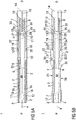
- Figure 1 shows two longitudinal sections in different section planes of an auto-injector 1, the different section planes approximately 90° rotated to each other, wherein the auto-injector 1 is in an initial state prior to starting an injection.
- the auto-injector 1 comprises a chassis 2.
- a syringe 3, e.g. a Hypak syringe, with a hollow injection needle 4 is arranged in a proximal part of the auto-injector 1.
- a protective needle shield 5 is attached to the needle 4.
- a stopper 6 is arranged for sealing the syringe 3 distally and for displacing a liquid medicament M through the hollow needle 4.
- the syringe 3 is held in a tubular carrier 7 and supported at its proximal end therein.
- the carrier 7 is slidably arranged in the chassis 2.
- a drive spring 8 in the shape of a compression spring is arranged in a distal part of the carrier 7.
- a plunger 9 serves for forwarding the force of the drive spring 8 to the stopper 6.
- the drive spring 8 is loaded between a distal carrier end face 10 of the carrier 7 and a thrust face on two resilient arms 11 arranged distally on the plunger 9.
- a wrap-over trigger sleeve 12 is arranged over the distal end D of the auto-injector 1 extending almost over the whole length of the auto-injector 1.
- a first boss 13 protrudes from a distal trigger end face 14 of the trigger sleeve 12 in proximal direction P between the two resilient arms 11 thus preventing them from flexing towards each other.
- the resilient arms 11 are caught behind respective protrusions 15 in the carrier 7 in a manner to prevent translation of the plunger 9 in proximal direction P.
- the protrusions 15 are distally ramped in a manner to flex the resilient arms 11 inwards under load of the drive spring 8, which is prevented by the first boss 13 in the initial state.
- the carrier 7 is locked to the chassis 2 near the proximal end P of the auto-injector 1 by two resilient clips 16 on the chassis 2 engaged in respective apertures 17 in the carrier 7.
- the resilient clips 16 are outwardly supported by respective second bosses 18 in the trigger sleeve 12 so as to prevent the resilient clips 16 from flexing outwards and disengaging the carrier 7 from the chassis 2.
- a control spring 19 in the shape of another compression spring is arranged around the carrier 7 and acts between a proximal collar 20 and a distal collar 21.
- the proximal collar 20 is mounted on a thread 22 on the carrier 7 (cf. figure 9 ) but is also splined to the trigger sleeve 12 by a pin 23 on the outer surface of the proximal collar 20 running in a first longitudinal groove 24 in the trigger sleeve 12 (cf. figure 10 ). Therefore the load from the proximal end of the control spring 19 is coupled through to the carrier 7 in the initial state.
- the distal collar 21 is coupled to the trigger sleeve 12 by a bayonet fitting but is also splined to the carrier 7, thus preventing the bayonet from releasing.
- the bayonet comprises a number of circumferentially arranged third bosses 25 on the inner surface of the trigger sleeve 12 and a corresponding number of circumferentially arranged fourth bosses 26 on the outer surface of the distal collar 21. In the initial state corresponding pairs of third bosses 25 and fourth bosses 26 are essentially aligned in a manner to abut against each other thus preventing translation of the distal collar 21 in distal direction D (cf. figure 10 ).
- the spline engagement comprises a number of longitudinal splines 27 on the carrier 7 each one engaged with a respective second longitudinal groove 28 on the inner surface of the distal collar 21 (cf. figures 9 and 10 ) thus restricting relative rotation of the distal collar 21 and the carrier 7 and consequently preventing disengagement of the bayonet.
- the trigger sleeve 12 is enabled to move in proximal direction P with respect to the carrier 7 against the force of the control spring 19. As the carrier 7 is initially locked to the chassis 2, translation of the trigger sleeve 12 in proximal direction P compresses the control spring 19, wherein the proximal collar 20 remains in the position of the initial state and wherein the distal collar 21 is translated with the trigger sleeve 12.
- the extension of the trigger sleeve 12 in distal direction D relative to the chassis 2 may be defined by a shoulder on the chassis 2 contacting a face on the trigger sleeve 12 (not illustrated).
- a sequence of operation of the auto-injector 1 is as follows:
- the protective needle shield 5 is removed from the proximal end P.
- the needle 4 is now exposed but still a safe distance back within the chassis 2 to protect the user from accidental needle stick injuries.
- the carrier 7 exhibits a retainer pocket 29 for accommodating a finger flange 30 of the syringe 3.
- the trigger sleeve 12 comprises a widened portion 31 for accommodating the retainer pocket 29 in a manner to restrict relative rotation of the trigger sleeve 12 and the carrier 7 while allowing translation in longitudinal direction. Thus rotation of the needle 4 is prevented. Any axial load applied to the carrier 7 during removal of the protective needle shield 5 is resolved through the carrier 7 locked to the chassis 2 by the resilient clip 16.
- the chassis 2 abuts against the trigger sleeve 12 at a stop 35 in a manner to prevent further translation of the chassis 2 in proximal direction P.
- axial load applied to the chassis 2 is thus resolved through the trigger sleeve 12 which would be held by a user. Removal of the protective needle shield 5 may be facilitated by a cap arranged on the proximal end P in the initial state, the cap engaged with the protective needle shield 5 (cap is not illustrated).
- the user i.e. the patient or a caregiver places the proximal end P of the auto-injector 1 on the injection site, e. g. the patient's skin and pushes the trigger sleeve 12 against the injection site (see figure 2 ).
- the chassis 2 together with all internal parts, translates in distal direction D into the trigger sleeve 12 .
- the user would visualise this translation of the chassis 2 as depression of a skin-contact shroud.
- the control spring 19 opposes this motion but is specified such that its spring rate and preload are low enough for this to feel natural. This translation is completely reversible, i.e.
- the user can place the auto-injector on the injection site, depress the chassis 2 (skin-contact-shroud) and remove the auto-injector 1 from the injection site without activating it, thereby allowing the chassis 2 and the trigger sleeve 12 to return to their initial position under load of the control spring 19.
- the auto-injector 1 may optionally have a two-stage firing mechanism. In this case, further translation from the position in figure 2 would be opposed by a detent mechanism (not illustrated).
- the user When ready to do so, the user continues to push the proximal end P of the auto-injector against the injection site while holding the trigger sleeve 12.
- the chassis 2, together with all the internal parts locked to it moves relative to the trigger sleeve 12 in distal direction D until the carrier end face 10 comes into contact with the trigger end face 14 at the distal end D of the auto-injector 1 (see figure 3 ).
- the second boss 18 locking the carrier 7 to the chassis 2 has moved to a position where the resilient clip 16 is allowed to flex outwards due to its ramped engagement with the carrier 7, which is biased in proximal direction P by the control spring 19 pushing against the proximal collar 20.
- the lock between the chassis 2 and the carrier 7 is thus released.
- the control spring 19 then forces the carrier 7 to move in proximal direction P along with the syringe 3 and the needle 4 thus inserting the needle 4 into the injection site (see figure 4 ).
- Figure 5 shows the carrier 7, the syringe 3 and the needle 4 fully advanced into a maximum proximal position defining an injection depth.
- This maximum proximal position is limited by contact of the retainer pocket 29 with the chassis 2.
- the carrier 7, syringe 3, needle 4, drive spring 8 and plunger 9 have translated relative to the trigger sleeve 12 so far that the first boss 13 is removed from between the resilient arms 11 thus releasing the plunger 9.
- the drive spring 8 pushes the resilient arms 11 over the protrusions 15 in proximal direction P due to their ramped engagement and the plunger 9 starts translating in proximal direction P under load of the drive spring 8.
- the drive spring 8 expands, the plunger 9 contacts the stopper 6 and the medicament M is expelled through the needle 4.
- the chassis 2 together with all internal components extend out of the trigger sleeve 12 in proximal direction D by the control spring 19 acting between the distal collar 21 locked to the trigger sleeve 12 and the proximal collar 20 locked to the carrier 7.
- the needle 4 is not yet withdrawn from the injection site during this motion since this would make the auto-injector 1 sensitive to the motion of the trigger sleeve 12 relative to the injection site during delivery of the medicament M, resulting in potential premature needle retraction should the user inadvertently move the auto-injector 1 slightly during the injection process.
- the initial needle insertion depth does not rely upon full depression of the chassis 2 (skin interlock) - i.e. the insertion depth is defined with respect to the chassis 2.
- the point at which retraction of the needle 4 is triggered is slightly before the chassis 2 has fully extended to the initial position to allow of part tolerance and ensure retraction always occurs before the chassis 2 stops moving relative to the sleeve trigger 12. However, it would be possible to configure the chassis 2 to have a more or less proximal position when removed from the injection site.
- the distal collar 21 axially fixed relative to the trigger sleeve 12 moves along the spline 27 on the carrier 7.
- the bayonet coupling with the trigger sleeve 12 is released.
- the corresponding pairs of third bosses 25 and fourth bosses 26 become misaligned in a manner to allow the third bosses 25 to pass through gaps between the fourth bosses 26 and vice versa thus allowing translation of the distal collar 21 in distal direction D.
- the distal collar 21 contacts an external shoulder 33 on the carrier 7 thus resolving load from the distal end of the control spring 19 into the carrier 7.
- the auto-injector 1 may be configured to retract the carrier 7 until the carrier end face 10 abuts against the trigger end face 14.
- the carrier 7 may be locked to the chassis 2 at this point by a clip (not illustrated) to prevent it moving under inertial forces when heavily shaken.
- the auto-injector 1 may optionally have a two-stage firing mechanism.
- the user i.e. the patient or a caregiver places the proximal end P of the auto-injector 1 on the injection site, e. g. the patient's skin and pushes the trigger sleeve 12 against the injection site.
- the chassis 2 together with all internal parts, translates in distal direction D into the trigger sleeve 12 until further translation is prevented by a detent mechanism (not illustrated).
- the user would visualise this translation of the chassis 2 as depression of a skin-contact shroud.
- the control spring 19 opposes this motion but is specified such that its spring rate and preload are low enough for this to feel natural.
- This translation is completely reversible, i.e. the user can place the auto-injector on the injection site, depress the chassis 2 (skin-contact-shroud) up to the position of the detent and remove the auto-injector 1 from the injection site without activating it, thereby allowing the chassis 2 and the trigger sleeve 12 to return to their initial position under load of the control spring 19. Aside from the detent the operation of the auto-injector 1 is identical to the description above.
- Viewing windows 34 are arranged in the shape of apertures in the trigger sleeve 12, in the chassis 2 and in the carrier 7 for inspecting the syringe contents.
Abstract
Description
- The invention relates to an auto-injector for administering a dose of a liquid medicament according to the preamble of
claim 1 and to a method for operating an auto-injector. - Administering an injection is a process which presents a number of risks and challenges for users and healthcare professionals, both mental and physical.
- Injection devices (i.e. devices capable of delivering medicaments from a medication container) typically fall into two categories - manual devices and auto-injectors.
- In a manual device - the user must provide the mechanical energy to drive the fluid through the needle. This is typically done by some form of button / plunger that has to be continuously pressed by the user during the injection. There are numerous disadvantages to the user from this approach. If the user stops pressing the button/ plunger then the injection will also stop. This means that the user can deliver an underdose if the device is not used properly (i.e. the plunger is not fully pressed to its end position). Injection forces may be too high for the user, in particular if the patient is elderly or has dexterity problems.
- The extension of the button/plunger may be too great. Thus it can be inconvenient for the user to reach a fully extended button. The combination of injection force and button extension can cause trembling / shaking of the hand which in turn increases discomfort as the inserted needle moves.
- Auto-injector devices aim to make self-administration of injected therapies easier for patients. Current therapies delivered by means of self-administered injections include drugs for diabetes (both insulin and newer GLP-1 class drugs), migraine, hormone therapies, anticoagulants etc.
- Auto-injectors are devices which completely or partially replace activities involved in parenteral drug delivery from standard syringes. These activities may include removal of a protective syringe cap, insertion of a needle into a patient's skin, injection of the medicament, removal of the needle, shielding of the needle and preventing reuse of the device. This overcomes many of the disadvantages of manual devices. Injection forces / button extension, hand-shaking and the likelihood of delivering an incomplete dose are reduced. Triggering may be performed by numerous means, for example a trigger button or the action of the needle reaching its injection depth. In some devices the energy to deliver the fluid is provided by a spring.
-
US 2002/0095120 A1 discloses an automatic injection device which automatically injects a pre-measured quantity of fluid medicine when a tension spring is released. The tension spring moves an ampoule and the injection needle from a storage position to a deployed position when it is released. The content of the ampoule is thereafter expelled by the tension spring forcing a piston forward inside the ampoule. After the fluid medicine has been injected, torsion stored in the tension spring is released and the injection needle is automatically retracted back to its original storage position. - High viscosity medicaments require high forces for expelling them through the relatively thin injection needle. To achieve these forces strong drive springs are needed. This can lead to a high impact felt by the user when inserting the needle into the skin and to high forces felt by the user when triggering the injection.
- It is an object of the present invention to provide an improved auto-injector and an improved method for operating an auto-injector.
- The object is achieved by an auto-injector according to
claim 1 and by a method according toclaim 9. - In the context of this specification the term proximal refers to the direction pointing towards the patient during an injection while the term distal refers to the opposite direction pointing away from the patient.
- Preferred embodiments of the invention are given in the dependent claims.
- According to the invention an auto-injector for administering a dose of a liquid medicament comprises:
- a tubular chassis,
- a carrier subassembly comprising a tubular carrier slidably arranged relative to the chassis and partially arranged in the chassis, the carrier containing a syringe with a hollow injection needle, a drive spring and a plunger for forwarding load of the drive spring to a stopper of the syringe, wherein the syringe is locked for joint axial translation with the carrier,
- a wrap-over trigger sleeve arranged over the distal end of the auto-injector, the trigger sleeve extending at least almost over the whole length of the auto-injector,
- a control spring arranged around the carrier,
- first interlock means for coupling a proximal end of the control spring to either the carrier for advancing it for needle insertion or to the chassis for needle retraction depending on the relative axial position of the carrier and the trigger sleeve,
- second interlock means arranged for releasing the drive spring for injection when the carrier has at least almost reached an injection depth during needle insertion,
- third interlock means arranged for coupling the chassis to the carrier for joint axial translation relative to the trigger sleeve, wherein the third interlock means are arranged to decouple the chassis from the carrier upon translation of the trigger sleeve in proximal direction relative to the chassis thus releasing the control spring for needle insertion,
- fourth interlock means arranged for coupling a distal end of the control spring to either the carrier for needle retraction or to the trigger sleeve otherwise.
- The carrier subassembly with the integrated drive spring allows for employing a strong drive spring without any impact on the user when triggering the auto-injector or during needle insertion since these actions are achieved or opposed by the control spring which can be specified considerably weaker than the drive spring. This allows for delivering highly viscous medicaments.
- Releasing the drive spring upon the needle reaching an injection depth avoids a so called wet injection, i.e. medicament leaking out of the needle which is a problem in conventional art auto-injectors, where both needle insertion and injection are achieved by pushing on the stopper.
- The auto-injector according to the invention has a particularly low part count compared to most conventional auto-injectors thus reducing manufacturing costs. The arrangement with separate control spring and drive spring for fluid injection allows for using one design for different viscosity liquids by just changing the drive spring, and for different volumes just by changing the length of the plunger. This is an advantage over conventional art designs where the main spring also powers needle insertion and/or retraction.
- In an initial as delivered state of the auto-injector the proximal end of the control spring is coupled to the carrier by the first interlock means, release of the drive spring is prevented by the second interlock means, decoupling of the chassis from the carrier is prevented by the third interlock means and the distal end of the control spring is coupled to the trigger sleeve.
- In order to trigger an injection the auto-injector has to be pressed against an injection site, e.g. a patient's skin. A user, e.g. the patient or a caregiver, grabs the wrap-over trigger sleeve with their whole hand and pushes the chassis protruding from the proximal end against the injection site. The auto-injector is thus particularly well suited for people with dexterity problems since, as opposed to conventional art auto-injectors, triggering does not require operation of small buttons by single fingers. Instead, the whole hand is used.
- When pushed against the injection site, the trigger sleeve translates in proximal direction relative to the chassis against the force of the control spring. The third interlock means disengages when the trigger sleeve is at least almost fully translated thereby releasing the control spring for advancing the carrier subassembly for needle insertion.
- As the needle translated with the carrier subassembly at least almost reaches an injection depth the drive spring is released by the second interlock means. The drive spring advances the plunger and the stopper in proximal direction for at least partially delivering the medicament.
- If the auto-injector is removed from the injection site after the stopper has bottomed out in the syringe or mid injection, the trigger sleeve is translated in distal direction under load of the control spring relative to the carrier subassembly.
- As the trigger sleeve reaches a defined position relative to the carrier during that motion the proximal end of the control spring is decoupled from the carrier and coupled to the chassis by the first interlock means. Furthermore the distal end of the control spring is decoupled from the trigger sleeve and coupled to the carrier by the fourth interlock means.
- As the control spring now pushes against the chassis in proximal direction and against the carrier in distal direction the carrier subassembly is retracted into the chassis into a needle safe position by the control spring.
- The first interlock means may comprise a proximal collar for transmitting load of the proximal end of the control spring. The proximal collar is engaged on a thread on the carrier in the initial state. The proximal collar has a pin arranged to be splined to a first longitudinal groove in the trigger sleeve in the initial state so as to prevent rotation of the proximal collar and to couple it to the carrier by pushing on the thread. Upon translation of the chassis and carrier in proximal direction relative to the trigger sleeve during removal of the auto-injector from the injection site the pin travels beyond a proximal end of the first longitudinal groove, e.g. into a clearance and is thus released so the proximal collar can rotate and translate relative to the carrier under load of the control spring, i.e. the proximal collar is decoupled from the carrier. The control spring translates the proximal collar in proximal direction until it abuts against the chassis.
- The second interlock means may comprise two resilient arms arranged distally on the plunger. The resilient arms exhibit a thrust face for a proximal end of the drive spring. A distal end of the drive spring acts against the carrier, e.g. a carrier end face. A first boss protrudes from a distal trigger end face of the trigger sleeve in proximal direction into the carrier. The first boss is arranged between the two resilient arms in the initial state thus preventing them from flexing towards each other. A number of protrusions are arranged in the carrier for respectively catching one of the resilient arms in a manner to prevent translation of the plunger in proximal direction in the initial state. During needle insertion the carrier is translated in proximal direction relative to the trigger sleeve. The boss is thus removed from between the resilient arms when the carrier has at least almost reached the injection depth during needle insertion thus allowing the resilient arms to flex inwards due to their ramped engagement to the protrusions under load of the drive spring. Hence, the plunger is released for advancing the stopper and delivering the medicament.
- A ramped engagement in the terminology of this specification is an engagement between two components with at least one of them having a ramp for engaging the other component in such a manner that one of the components is flexed aside when the components are axially pushed against each other provided this component is not prevented from flexing aside.
- The third interlock means may comprise at least one resilient clip on the chassis engaged in a respective aperture in the carrier in the initial state for locking the chassis to the carrier. At least one second boss is arranged in the trigger sleeve for outwardly supporting the resilient clip so as to prevent the resilient clip from flexing outwards and disengaging the carrier from the chassis in the initial state. The second boss is removed from behind the resilient clip on translation of the trigger sleeve in proximal direction relative to the chassis when the auto-injector is being pushed against the injection site. The resilient clip is subsequently flexed outwards due to its ramped engagement with the carrier under load of the control spring releasing the control spring for needle insertion.
- The fourth interlock means may comprise a distal collar for transmitting load of the distal end of the control spring. The distal collar and the trigger sleeve may be coupled by a bayonet fitting restricting translation of the distal collar relative to the trigger sleeve in distal direction in at least one locked angular position of the distal collar. In at least one unlocked angular position of the bayonet fitting the distal collar can translate relative to the trigger sleeve in distal direction. The respective angular position is determined by a splined engagement of the distal collar with the carrier. The distal collar is in the locked angular position in the initial state and remains there due to the splined engagement. Upon translation of the chassis and carrier in proximal direction during removal of the auto-injector from the injection site the distal collar is rotated into the unlocked angular position by the splined engagement thus decoupling it from the trigger sleeve. The distal collar is subsequently translated in distal direction relative to the trigger sleeve under load of the control spring into a position where it abuts against an external shoulder on the carrier which is then translated in distal direction for retraction.
- The bayonet fitting may comprise at least one circumferentially arranged third boss, preferably a number of equally spaced third bosses on the inner surface of the trigger sleeve and a corresponding number of circumferentially arranged fourth bosses on the outer surface of the distal collar. In the locked angular position corresponding pairs of third bosses and fourth bosses are essentially aligned in a manner to abut against each other thus preventing translation of the distal collar in distal direction. Upon translation of the chassis and carrier in proximal direction during removal of the auto-injector from the injection site the distal collar is rotated by the splined engagement into the unlocked angular position, thereby misaligning the corresponding pairs of third bosses and fourth bosses in a manner to allow translation of the distal collar in distal direction, e. g. by the third bosses passing through gaps between the fourth bosses and vice versa.
- The splined engagement may comprise at least one longitudinal spline on the carrier engaged with a respective second longitudinal groove on the inner surface of the distal collar. The spline is essentially parallel for maintaining the distal collar in the locked angular position but ends with a lead screw thread near its distal end for rotating the distal collar into the unlocked angular position. The second longitudinal groove is guided on an essentially parallel part of the spline in the initial state for maintaining the distal collar in the locked angular position until removal of the auto-injector from the injection site. The second longitudinal groove is moved along the spline upon translation of the chassis and carrier in proximal direction when the auto-injector is removed from the injection site and enters the lead screw thread for rotating the distal collar into the unlocked angular position.
- It goes without saying that splines or threads between two components may be arranged either way with the spline on the first and the groove on the other component or the other way round.
- In order to ensure needle safety under inertial forces, e.g. when the auto-injector is heavily shaken after use a snap feature may be provided between the chassis and the carrier for locking them together when the carrier is retracted into the needle safe position.
- A detent mechanism may be arranged for opposing translation of the chassis relative to the trigger sleeve for triggering needle insertion thus providing the auto-injector with a two-stage firing mechanism.
- The auto-injector may preferably be used for subcutaneous or intra-muscular injection, particularly for delivering one of an analgetic, an anticoagulant, insulin, an insulin derivate, heparin, Lovenox, a vaccine, a growth hormone, a peptide hormone, a proteine, antibodies and complex carbohydrates.
- Further scope of applicability of the present invention will become apparent from the detailed description given hereinafter. However, it should be understood that the detailed description and specific examples, while indicating preferred embodiments of the invention, are given by way of illustration only, since various changes and modifications within the spirit and scope of the invention will become apparent to those skilled in the art from this detailed description.
- The present invention will become more fully understood from the detailed description given hereinbelow and the accompanying drawings which are given by way of illustration only, and thus, are not limitive of the present invention, and wherein:
- Figure 1
- is an auto-injector with a syringe in an initial state prior to actuation,
- Figure 2
- is the auto-injector with a protective needle shield removed and pushed against an injection site,
- Figure 3
- is the auto-injector with a sleeve trigger button fully depressed,
- Figure 4
- is the auto-injector with an injection needle inserted into the injection site,
- Figure 5
- is the auto-injector with a drive spring released for injection,
- Figure 6
- is the auto-injector with the syringe emptied,
- Figure 7
- is the auto-injector removed from the injection site after the end of injection,
- Figure 8
- is the auto-injector with the syringe and needle retracted into a needle safe position,
- Figure 9
- is a detail view of the auto-injector with a control spring, a proximal collar and a distal collar in the state as in
figure 7 , and - Figure 10
- is another detail view of the auto-injector with the control spring, the proximal collar and the distal collar in the state as in
figure 7 . - Corresponding parts are marked with the same reference symbols in all figures.
-
Figure 1 shows two longitudinal sections in different section planes of an auto-injector 1, the different section planes approximately 90° rotated to each other, wherein the auto-injector 1 is in an initial state prior to starting an injection. The auto-injector 1 comprises achassis 2. Asyringe 3, e.g. a Hypak syringe, with ahollow injection needle 4 is arranged in a proximal part of the auto-injector 1. When the auto-injector 1 or thesyringe 3 is assembled aprotective needle shield 5 is attached to theneedle 4. Astopper 6 is arranged for sealing thesyringe 3 distally and for displacing a liquid medicament M through thehollow needle 4. Thesyringe 3 is held in atubular carrier 7 and supported at its proximal end therein. Thecarrier 7 is slidably arranged in thechassis 2. - A
drive spring 8 in the shape of a compression spring is arranged in a distal part of thecarrier 7. Aplunger 9 serves for forwarding the force of thedrive spring 8 to thestopper 6. - The
drive spring 8 is loaded between a distal carrier end face 10 of thecarrier 7 and a thrust face on tworesilient arms 11 arranged distally on theplunger 9. - A wrap-over
trigger sleeve 12 is arranged over the distal end D of the auto-injector 1 extending almost over the whole length of the auto-injector 1. Afirst boss 13 protrudes from a distal trigger end face 14 of thetrigger sleeve 12 in proximal direction P between the tworesilient arms 11 thus preventing them from flexing towards each other. Outwardly theresilient arms 11 are caught behindrespective protrusions 15 in thecarrier 7 in a manner to prevent translation of theplunger 9 in proximal direction P. Theprotrusions 15 are distally ramped in a manner to flex theresilient arms 11 inwards under load of thedrive spring 8, which is prevented by thefirst boss 13 in the initial state. - The
carrier 7 is locked to thechassis 2 near the proximal end P of the auto-injector 1 by tworesilient clips 16 on thechassis 2 engaged inrespective apertures 17 in thecarrier 7. In the initial state theresilient clips 16 are outwardly supported by respectivesecond bosses 18 in thetrigger sleeve 12 so as to prevent theresilient clips 16 from flexing outwards and disengaging thecarrier 7 from thechassis 2. - A
control spring 19 in the shape of another compression spring is arranged around thecarrier 7 and acts between aproximal collar 20 and adistal collar 21. Theproximal collar 20 is mounted on athread 22 on the carrier 7 (cf.figure 9 ) but is also splined to thetrigger sleeve 12 by apin 23 on the outer surface of theproximal collar 20 running in a firstlongitudinal groove 24 in the trigger sleeve 12 (cf.figure 10 ). Therefore the load from the proximal end of thecontrol spring 19 is coupled through to thecarrier 7 in the initial state. Thedistal collar 21 is coupled to thetrigger sleeve 12 by a bayonet fitting but is also splined to thecarrier 7, thus preventing the bayonet from releasing. The bayonet comprises a number of circumferentially arrangedthird bosses 25 on the inner surface of thetrigger sleeve 12 and a corresponding number of circumferentially arrangedfourth bosses 26 on the outer surface of thedistal collar 21. In the initial state corresponding pairs ofthird bosses 25 andfourth bosses 26 are essentially aligned in a manner to abut against each other thus preventing translation of thedistal collar 21 in distal direction D (cf.figure 10 ). The spline engagement comprises a number oflongitudinal splines 27 on thecarrier 7 each one engaged with a respective secondlongitudinal groove 28 on the inner surface of the distal collar 21 (cf.figures 9 and10 ) thus restricting relative rotation of thedistal collar 21 and thecarrier 7 and consequently preventing disengagement of the bayonet. - The
trigger sleeve 12 is enabled to move in proximal direction P with respect to thecarrier 7 against the force of thecontrol spring 19. As thecarrier 7 is initially locked to thechassis 2, translation of thetrigger sleeve 12 in proximal direction P compresses thecontrol spring 19, wherein theproximal collar 20 remains in the position of the initial state and wherein thedistal collar 21 is translated with thetrigger sleeve 12. The extension of thetrigger sleeve 12 in distal direction D relative to thechassis 2 may be defined by a shoulder on thechassis 2 contacting a face on the trigger sleeve 12 (not illustrated). - A sequence of operation of the auto-
injector 1 is as follows:
Theprotective needle shield 5 is removed from the proximal end P. Theneedle 4 is now exposed but still a safe distance back within thechassis 2 to protect the user from accidental needle stick injuries. Thecarrier 7 exhibits aretainer pocket 29 for accommodating afinger flange 30 of thesyringe 3. Thetrigger sleeve 12 comprises a widenedportion 31 for accommodating theretainer pocket 29 in a manner to restrict relative rotation of thetrigger sleeve 12 and thecarrier 7 while allowing translation in longitudinal direction. Thus rotation of theneedle 4 is prevented.
Any axial load applied to thecarrier 7 during removal of theprotective needle shield 5 is resolved through thecarrier 7 locked to thechassis 2 by theresilient clip 16. Thechassis 2 abuts against thetrigger sleeve 12 at astop 35 in a manner to prevent further translation of thechassis 2 in proximal direction P. As theprotective needle shield 5 is being removed axial load applied to thechassis 2 is thus resolved through thetrigger sleeve 12 which would be held by a user. Removal of theprotective needle shield 5 may be facilitated by a cap arranged on the proximal end P in the initial state, the cap engaged with the protective needle shield 5 (cap is not illustrated). - In order to trigger an injection, the user, i.e. the patient or a caregiver places the proximal end P of the auto-
injector 1 on the injection site, e. g. the patient's skin and pushes thetrigger sleeve 12 against the injection site (seefigure 2 ). Thechassis 2, together with all internal parts, translates in distal direction D into thetrigger sleeve 12 .The user would visualise this translation of thechassis 2 as depression of a skin-contact shroud. Thecontrol spring 19 opposes this motion but is specified such that its spring rate and preload are low enough for this to feel natural. This translation is completely reversible, i.e. the user can place the auto-injector on the injection site, depress the chassis 2 (skin-contact-shroud) and remove the auto-injector 1 from the injection site without activating it, thereby allowing thechassis 2 and thetrigger sleeve 12 to return to their initial position under load of thecontrol spring 19. - The auto-
injector 1 may optionally have a two-stage firing mechanism. In this case, further translation from the position infigure 2 would be opposed by a detent mechanism (not illustrated). - When ready to do so, the user continues to push the proximal end P of the auto-injector against the injection site while holding the
trigger sleeve 12. Thechassis 2, together with all the internal parts locked to it moves relative to thetrigger sleeve 12 in distal direction D until thecarrier end face 10 comes into contact with the trigger end face 14 at the distal end D of the auto-injector 1 (seefigure 3 ). - Just before this position is reached, the
second boss 18 locking thecarrier 7 to thechassis 2 has moved to a position where theresilient clip 16 is allowed to flex outwards due to its ramped engagement with thecarrier 7, which is biased in proximal direction P by thecontrol spring 19 pushing against theproximal collar 20. The lock between thechassis 2 and thecarrier 7 is thus released. Thecontrol spring 19 then forces thecarrier 7 to move in proximal direction P along with thesyringe 3 and theneedle 4 thus inserting theneedle 4 into the injection site (seefigure 4 ). -
Figure 5 shows thecarrier 7, thesyringe 3 and theneedle 4 fully advanced into a maximum proximal position defining an injection depth. This maximum proximal position is limited by contact of theretainer pocket 29 with thechassis 2. Just before the maximum proximal position is reached, thecarrier 7,syringe 3,needle 4, drivespring 8 andplunger 9 have translated relative to thetrigger sleeve 12 so far that thefirst boss 13 is removed from between theresilient arms 11 thus releasing theplunger 9. Thedrive spring 8 pushes theresilient arms 11 over theprotrusions 15 in proximal direction P due to their ramped engagement and theplunger 9 starts translating in proximal direction P under load of thedrive spring 8. Thedrive spring 8 expands, theplunger 9 contacts thestopper 6 and the medicament M is expelled through theneedle 4. - This motion of the
stopper 6 continues until thestopper 6 bottoms out in thesyringe 3, thereby fully emptying thesyringe 3. The user would be asked to keep pressure on the injection site for a short period of time, e.g. ten seconds to ensure this is achieved (seefigure 6 ). - As the user withdraws the auto-
injector 1 from the injection site, thechassis 2 together with all internal components extend out of thetrigger sleeve 12 in proximal direction D by thecontrol spring 19 acting between thedistal collar 21 locked to thetrigger sleeve 12 and theproximal collar 20 locked to thecarrier 7. Theneedle 4 is not yet withdrawn from the injection site during this motion since this would make the auto-injector 1 sensitive to the motion of thetrigger sleeve 12 relative to the injection site during delivery of the medicament M, resulting in potential premature needle retraction should the user inadvertently move the auto-injector 1 slightly during the injection process. As a consequence of this feature the initial needle insertion depth does not rely upon full depression of the chassis 2 (skin interlock) - i.e. the insertion depth is defined with respect to thechassis 2. - The point at which retraction of the
needle 4 is triggered is slightly before thechassis 2 has fully extended to the initial position to allow of part tolerance and ensure retraction always occurs before thechassis 2 stops moving relative to thesleeve trigger 12. However, it would be possible to configure thechassis 2 to have a more or less proximal position when removed from the injection site. - Just before the
chassis 2 reaches the end of travel during this translation, the spline feature between theproximal collar 20 and thetrigger sleeve 12 is released by thepin 23 of theproximal collar 20 travelling beyond the firstlongitudinal groove 24. This allows theproximal collar 20 to rotate on thethread 22 relative to thecarrier 7. As theproximal collar 20 rotates it translates in proximal direction P relative to thecarrier 7 and then decouples from it eventually coming in contact with the chassis 2 (seefigure 7 ). Now the load on the proximal end of thecontrol spring 19 is no longer applied to thecarrier 7 but to thechassis 2.Figures 9 and10 show thecontrol spring 19, theproximal collar 20, and thedistal collar 21 in this situation. Some components are drawn with dotted lines as transparent parts in order to make interactions comprehensible. It has to be understood that in reality these components do not need to be transparent. - As the
chassis 2 continues to move in proximal direction P towards its final proximal position thedistal collar 21 axially fixed relative to thetrigger sleeve 12 moves along thespline 27 on thecarrier 7. Thespline 27, which is parallel to the longitudinal axis for the most part, ends with alead screw thread 32. This causes thedistal collar 21 to rotate relative to thecarrier 7. As thedistal collar 21 rotates, the bayonet coupling with thetrigger sleeve 12 is released. The corresponding pairs ofthird bosses 25 andfourth bosses 26 become misaligned in a manner to allow thethird bosses 25 to pass through gaps between thefourth bosses 26 and vice versa thus allowing translation of thedistal collar 21 in distal direction D. Thedistal collar 21 contacts anexternal shoulder 33 on thecarrier 7 thus resolving load from the distal end of thecontrol spring 19 into thecarrier 7. - Now acting between the
carrier 7 and thechassis 2, thecontrol spring 19 withdraws thecarrier 7 inside thechassis 2, extracting the needle from the injection site in the process thus providing post injection needle safety. The auto-injector 1 may be configured to retract thecarrier 7 until thecarrier end face 10 abuts against thetrigger end face 14. Thecarrier 7 may be locked to thechassis 2 at this point by a clip (not illustrated) to prevent it moving under inertial forces when heavily shaken. - If the user were to remove the auto-
injector 1 from the injection site prior to full syringe emptying, the described motion of thechassis 2 would still be achieved. However, in that case thesyringe 3 would be fully emptied after removal from the injection site. - The auto-
injector 1 may optionally have a two-stage firing mechanism. In this case, in order to trigger an injection, the user, i.e. the patient or a caregiver places the proximal end P of the auto-injector 1 on the injection site, e. g. the patient's skin and pushes thetrigger sleeve 12 against the injection site. Thechassis 2, together with all internal parts, translates in distal direction D into thetrigger sleeve 12 until further translation is prevented by a detent mechanism (not illustrated). The user would visualise this translation of thechassis 2 as depression of a skin-contact shroud. Thecontrol spring 19 opposes this motion but is specified such that its spring rate and preload are low enough for this to feel natural. This translation is completely reversible, i.e. the user can place the auto-injector on the injection site, depress the chassis 2 (skin-contact-shroud) up to the position of the detent and remove the auto-injector 1 from the injection site without activating it, thereby allowing thechassis 2 and thetrigger sleeve 12 to return to their initial position under load of thecontrol spring 19. Aside from the detent the operation of the auto-injector 1 is identical to the description above. -
Viewing windows 34 are arranged in the shape of apertures in thetrigger sleeve 12, in thechassis 2 and in thecarrier 7 for inspecting the syringe contents. -
Embodiment 1. Auto-injector (1) for administering a dose of a liquid medicament (M), comprising:- a tubular chassis (2),
- a carrier subassembly comprising a tubular carrier (7) slidably arranged relative to the chassis (2) and partially arranged in the chassis (2), the carrier (7) containing a syringe (3) with a hollow injection needle (4), a drive spring (8) and a plunger (9) for forwarding load of the drive spring (8) to a stopper (6) of the syringe (3), wherein the syringe (3) is locked for joint axial translation with the carrier (7),
- a wrap-over trigger sleeve (12) arranged over the distal end (D) of the auto-injector (1), the trigger sleeve (12) extending at least almost over the whole length of the auto-injector (1),
- a control spring (19) arranged around the carrier (7),
- first interlock means (20, 22, 23, 24) for coupling a proximal end of the control spring (19) to either the carrier (7) for advancing it for needle insertion or to the chassis (2) for needle retraction depending on the relative axial position of the carrier (7) and the trigger sleeve (12),
- second interlock means (11, 13, 15) arranged for releasing the drive spring (8) for injection when the carrier (7) has at least almost reached an injection depth during needle insertion,
- third interlock means (16, 17, 18) arranged for coupling the chassis (2) to the carrier (7) for joint axial translation relative to the trigger sleeve (12), wherein the third interlock means (16, 17, 18) are arranged to decouple the chassis (2) from the carrier (7) upon translation of the trigger sleeve (12) in proximal direction (P) relative to the chassis (2) thus releasing the control spring (19) for needle insertion,
- fourth interlock means (21, 25, 26, 28) arranged for coupling a distal end of the control spring (19) to either the carrier (7) for needle retraction or to the trigger sleeve (12) otherwise.
-
Embodiment 2. Auto-injector (1) according toembodiment 1, characterized in that the first interlock means (20, 22, 23, 24) comprises a proximal collar (20) for transmitting load of the proximal end of the control spring (19), the proximal collar (20) arranged to be engaged on a thread (22) on the carrier (7) in an initial state, the proximal collar (20) having a pin (23) arranged to be splined to a first longitudinal groove (24) in the trigger sleeve (12) in the initial state so as to prevent rotation of the proximal collar (20) and couple it to the carrier (7), wherein the first longitudinal groove (24) is arranged to release the pin (23) upon translation of the chassis (2) and carrier (7) in proximal direction (P) under load of the control spring (19) when the auto-injector (1) is removed from the injection site thereby allowing rotation and translation of the proximal collar (20) relative to the carrier (7) under load of the control spring (19) and subsequent abutting of the proximal collar (20) against the chassis (2). -
Embodiment 3. Auto-injector (1) according to one of theembodiments -
Embodiment 4. Auto-injector (1) according to one of the preceding embodiments, characterized in that the third interlock means (16, 17, 18) comprises at least one resilient clip (16) on the chassis (2) engageable in a respective aperture (17) in the carrier (7), wherein at least one second boss (18) is arranged in the trigger sleeve (12) for outwardly supporting the resilient clip (16) so as to prevent the resilient clip (16) from flexing outwards and disengaging the carrier (7) from the chassis (2), wherein the second boss (18) is arranged to be removed from behind the resilient clip (16) on translation of the trigger sleeve (12) in proximal direction (P) relative to the chassis (2) thereby allowing the resilient clip (16) to flex outwards due to its ramped engagement with the carrier (7) under load of the control spring (19). -
Embodiment 5. Auto-injector (1) according to one of the preceding embodiments, characterized in that the fourth interlock means (21, 25, 26, 28) comprise a distal collar (21) for transmitting load of the distal end of the control spring (19), the distal collar (21) and the trigger sleeve (12) having a bayonet fitting restricting translation of the distal collar (21) relative to the trigger sleeve (12) in distal direction (D) in at least one locked angular position of the distal collar (21) and allowing translation of the distal collar (21) relative to the trigger sleeve (12) in distal direction (D) in at least one unlocked angular position of the distal collar (21), wherein the respective angular position is determined by a splined engagement of the distal collar (21) with the carrier (7), wherein the distal collar (21) is arranged to be rotated into the unlocked angular position upon translation of the chassis (2) and carrier (7) in proximal direction (P) under load of the control spring (19) when the auto-injector (1) is removed from the injection site thereby allowing translation of the distal collar (21) relative to the trigger sleeve (21) under load of the control spring (19) in distal direction (D) and subsequent abutting of the distal collar (21) against an external shoulder (33) on the carrier (7) for retraction. -
Embodiment 6. Auto-injector (1) according toembodiment 5, characterized in that the bayonet fitting comprises at least one circumferentially arranged third boss (25) on the inner surface of the trigger sleeve (12) and a corresponding number of circumferentially arranged fourth bosses (26) on the outer surface of the distal collar (21), wherein in the locked angular position corresponding pairs of third bosses (25) and fourth bosses (26) are essentially aligned in a manner to abut against each other thus preventing translation of the distal collar (21) in distal direction (D), wherein in the unlocked angular position corresponding pairs of third bosses (25) and fourth bosses (26) become misaligned in a manner to allow translation of the distal collar (21) in distal direction (D). -
Embodiment 7. Auto-injector (1) according to one of theembodiments -
Embodiment 8. Auto-injector (1) according to one of the preceding embodiments, characterized in that a detent mechanism is provided for opposing translation of the chassis (2) relative to the trigger sleeve (12) for triggering needle insertion. -
Embodiment 9. Method for operating an auto-injector (1), the auto-injector (1) comprising:- a tubular chassis (2),
- a carrier subassembly comprising a tubular carrier (7) slidably arranged relative to the chassis (2) and partially arranged in the chassis (2), the carrier (7) containing a syringe (3) with a hollow injection needle (4), a drive spring (8) and a plunger (9) for forwarding load of the drive spring (8) to a stopper (6) of the syringe (3), wherein the syringe (3) is locked for joint axial translation with the carrier (7),
- a wrap-over trigger sleeve (12) arranged over the distal end (D) of the auto-injector (1), the trigger sleeve (12) extending at least almost over the whole length of the auto-injector (1),
- a control spring (19) arranged around the carrier (7),
- first interlock means (20, 22, 23, 24) for coupling a proximal end of the control spring (19) to either the carrier (7) or to the chassis (2),
- second interlock means (11, 13, 15) arranged for locking the drive spring (8),
- third interlock means (16, 17, 18) arranged for coupling the chassis (2) to the carrier (7),
- fourth interlock means (21, 25, 26, 28) arranged for coupling a distal end of the control spring (19) to either the carrier (7) or to the trigger sleeve (12),
- coupling the proximal end of the control spring (19) to the carrier (7) by the first interlock means (20, 23, 24), preventing release of the drive spring (8) by the second interlock means (11, 13, 15), preventing decoupling of the chassis (2) from the carrier (7) by the third interlock means (16, 17, 18) and coupling the distal end of the control spring (19) to the trigger sleeve (12) in an initial state,
- translating the trigger sleeve (12) in proximal direction (P) relative to the chassis (2) against the force of the control spring (19) when the proximal end (P) of the auto-injector (1) is being pushed against an injection site,
- disengaging the third interlock means (16, 17, 18) when the trigger sleeve (12) is at least almost fully translated thereby releasing the control spring (19) for advancing the carrier subassembly for needle insertion,
- releasing the drive spring (8) by the second interlock means (11, 13, 15) when the needle (4) at least almost reaches an injection depth during needle insertion, thereby allowing the drive spring (8) to advance the plunger (9) and the stopper (6) for at least partially delivering the medicament (M),
- translating the trigger sleeve (12) in distal direction (D) under load of the control spring (19) relative to the carrier subassembly on removal of the auto-injector (1) from the injection site,
- decoupling the proximal end of the control spring (19) from the carrier (7) and coupling it to the chassis (2) by the first interlock means (20, 23, 24) and decoupling the distal end of the control spring (19) from the trigger sleeve (12) and coupling it to the carrier (7) by the fourth interlock means (21, 25, 26, 28) when the trigger sleeve (12) reaches a defined position relative to the carrier (7),
- retracting the carrier subassembly into the chassis (2) into a needle safe position under load of the control spring (19).
-
Embodiment 10. Method according toembodiment 9, characterized in that the first interlock
means (20, 22, 23, 24) comprises a proximal collar (20) for transmitting load of the proximal end of the control spring (19), wherein the proximal collar (20) is engaged on a thread (22) on the carrier (7) in the initial state, wherein a pin (23) on the proximal collar (20) is splined to a first longitudinal groove (24) in the trigger sleeve (12) in the initial state so as to prevent rotation of the proximal collar (20) and couple it to the carrier (7), wherein upon translation of the chassis (2) and carrier (7) in proximal direction (P) during removal of the auto-injector (1) from the injection site the pin (23) travels beyond a proximal end of the first longitudinal groove (24), thereby the control spring (19) to rotate and translate the proximal collar (20) relative to the carrier (7) into a position where proximal collar (20) abuts against the chassis (2). -
Embodiment 11. Method according to one of theembodiments -
Embodiment 12. Method according to one of theembodiments 9 to 11, characterized in that the third interlock means (16, 17, 18) comprises at least one resilient clip (16) on the chassis (2) engaged in a respective aperture (17) in the carrier (7) in the initial state, wherein at least one second boss (18) is arranged in the trigger sleeve (12) for outwardly supporting the resilient clip (16) so as to prevent the resilient clip (16) from flexing outwards and disengaging the carrier (7) from the chassis (2) in the initial state, wherein the second boss (18) is removed from behind the resilient clip (16) on translation of the trigger sleeve (12) in proximal direction (P) relative to the chassis (2), wherein the resilient clip (16) is subsequently flexed outwards due to its ramped engagement with the carrier (7) under load of the control spring (19). -
Embodiment 13. Method according to one of the embodiments 9 to 12, characterized in that the fourth interlock means (21, 25, 26, 28) comprise a distal collar (21) for transmitting load of the distal end of the control spring (19), the distal collar (21) and the trigger sleeve (12) having a bayonet fitting restricting translation of the distal collar (21) relative to the trigger sleeve (12) in distal direction (D) in at least one locked angular position of the distal collar (21) and allowing translation of the distal collar (21) relative to the trigger sleeve (12) in distal direction (D) in at least one unlocked angular position of the distal collar (21), wherein the respective angular position is determined by a splined engagement of the distal collar (21) with the carrier (7), wherein the distal collar (21) is in the locked angular position in the initial state, wherein the distal collar (21) is rotated into the unlocked angular position by the splined engagement upon translation of the chassis (2) and carrier (7) in proximal direction (P) when the auto-injector (1) is removed from the injection site wherein the distal collar (21) is subsequently translated in distal direction (D) relative to the trigger sleeve (21) under load of the control spring (19) into a position where it abuts against an external shoulder (33) on the carrier (7) which is then translated in distal direction (D) for retraction. -
Embodiment 14. Method according toembodiment 13, characterized in that the bayonet fitting comprises at least one circumferentially arranged third boss (25) on the inner surface of the trigger sleeve (12) and a corresponding number of circumferentially arranged fourth bosses (26) on the outer surface of the distal collar (21), wherein in the initial state the bayonet fitting is set in the locked angular position by essentially aligning corresponding pairs of third bosses (25) and fourth bosses (26) in a manner to abut against each other thus preventing translation of the distal collar (21) in distal direction (D), wherein upon translation of the chassis (2) and carrier (7) in proximal direction (P) when the auto-injector (1) is removed from the injection site the distal collar (21) is rotated by the splined engagement into the unlocked angular position, thereby misaligning corresponding pairs of third bosses (25) and fourth bosses (26) in a manner to allow translation of the distal collar (21) in distal direction (D). -
Embodiment 15. Method according to one of theembodiments -
- 1
- auto-injector
- 2
- chassis
- 3
- syringe
- 4
- hollow injection needle
- 5
- protective needle shield
- 6
- stopper
- 7
- carrier
- 8
- drive spring
- 9
- plunger
- 10
- carrier end face
- 11
- resilient arm
- 12
- trigger sleeve
- 13
- first boss
- 14
- trigger end face
- 15
- protrusion
- 16
- resilient clip
- 17
- aperture
- 18
- second boss
- 19
- control spring
- 20
- proximal collar
- 21
- distal collar
- 22
- thread
- 23
- pin
- 24
- first longitudinal groove
- 25
- third boss
- 26
- fourth boss
- 27
- spline
- 28
- second longitudinal groove
- 29
- retainer pocket
- 30
- finger flange
- 31
- widened portion
- 32
- lead screw thread
- 33
- shoulder
- 34
- viewing window
- 35
- stop
- D
- distal end, distal direction
- M
- medicament
- P
- proximal end, proximal direction
Claims (14)
- Auto-injector (1) for administering a dose of a liquid medicament (M), comprising:- a tubular chassis (2),- a carrier subassembly comprising a tubular carrier (7) initially locked to the chassis (2) and partially arranged in the chassis (2), the carrier (7) containing a syringe (3) with a hollow injection needle (4), a drive spring (8) and a plunger (9) for forwarding load of the drive spring (8) to a stopper (6) of the syringe (3),- a wrap-over trigger sleeve (12) arranged over the distal end (D) of the auto-injector (1), the trigger sleeve (12) extending at least almost over the whole length of the auto-injector (1),- a control spring (19) arranged around the carrier (7),- a one-stage firing mechanism is provided for trigger an injection wherein the trigger sleeve (12) is movable in proximal direction (P) with respect to the carrier (7) and the chassis (2) against the force of the control spring (19).
- Auto-injector (1) according to claim 1, wherein the chassis (2) moves relative to the trigger sleeve (12) in distal direction (D) until a carrier end face (10) comes into contact with a trigger end face (14) at a distal end (D) of the auto-injector (1).
- Auto-injector (1) according to claim 1 or 2, wherein in an initial state of the auto-injector, the proximal end of the control spring (19) is coupled to the carrier (7) by first interlock means (11, 13, 15), release of the drive spring (8) is prevented by second interlock means, decoupling of the chassis (2) from the carrier (7) is prevented by third interlock means, and a distal end of the control spring (19) is coupled to the trigger sleeve (12) by fourth interlock means (21, 25, 26, 28).
- Auto-injector (1) according to claim 3, wherein the second interlock means (11, 13, 15) arranged for releasing the drive spring (8) for injection when the trigger sleeve (12) has been translated into the chassis (2) by at least almost an injection depth during needle insertion.
- Auto-injector (11) according to any one of the preceding claims, wherein the wrap-over trigger sleeve (12) is configured to grab with the whole hand to trigger an injection.
- Auto-injector (1) according to claim 1, wherein the syringe (3) is locked to the chassis (2), in particular by the carrier (7).
- Auto-injector (1) according to claim 1 or 2, wherein the control spring (19) biases the trigger sleeve (12) in the distal direction (D).
- Auto-injector (1) according to anyone of the preceding claims, characterized in that the second interlock means (11, 13, 15) for releasing the drive spring (8) for injection comprises two resilient arms (11) arranged distally on the plunger (9), the resilient arms (11) exhibiting a thrust face for the drive spring (8).
- Auto-injector (1) according to claim 8, wherein the distal end of the drive spring (8) acts against the carrier (7), in particular a carrier end face.
- Auto-injector (1) according to claim 8 or 9, wherein a first boss (13) protrudes from a distal trigger end face (14) of the trigger sleeve (12) in proximal direction (P), wherein the first boss (13) is arrangeable between the two resilient arms (11) thus preventing them from flexing towards each other in an initial state.
- Auto-injector (1) according to any one of the claims 8 to 10, wherein protrusions (15) are arranged in the carrier (7) for respectively catching one of the resilient arms (11) in a manner to prevent translation of the plunger (9) in proximal direction (P) in an initial state.
- Auto-injector (1) according to one of the preceding claims 3 to 11, characterized in that the fourth interlock means (21, 25, 26, 28) comprise a distal collar (21) for transmitting load of the distal end of the control spring (19), the distal collar (21) and the trigger sleeve (12) having a bayonet fitting restricting translation of the distal collar (21) relative to the trigger sleeve (12) in distal direction (D) in at least one locked angular position of the distal collar (21) and allowing translation of the distal collar (21) relative to the trigger sleeve (12) in distal direction (D) in at least one unlocked angular position of the distal collar (21).
- Auto-injector (1) according to claim 12, characterized in that the bayonet fitting comprises at least one circumferentially arranged inner boss (25) on the inner surface of the trigger sleeve (12) and a corresponding number of circumferentially arranged outer bosses (26) on the outer surface of the distal collar (21), wherein in the locked angular position corresponding pairs of inner bosses (25) and outer bosses (26) are essentially aligned in a manner to abut against each other thus preventing translation of the distal collar (21) in distal direction (D), wherein in the unlocked angular position corresponding pairs of inner bosses (25) and outer bosses (26) become misaligned in a manner to allow translation of the distal collar (21) in distal direction (D).
- Auto-injector (1) according to one of the claims 12 or 13, characterized in that the splined engagement comprises at least one longitudinal spline (27) on the carrier engaged with a respective second longitudinal groove (28) on the inner surface of the distal collar (21), wherein the spline (27) is essentially parallel for maintaining the distal collar (21) in the locked angular position but ends with a lead screw thread (32) near its distal end for rotating the distal collar (21) into the unlocked angular position.
Applications Claiming Priority (4)
| Application Number | Priority Date | Filing Date | Title |
|---|---|---|---|
| EP10186995A EP2438942A1 (en) | 2010-10-08 | 2010-10-08 | Auto-injector |
| US201161432260P | 2011-01-13 | 2011-01-13 | |
| EP11767241.0A EP2624889B1 (en) | 2010-10-08 | 2011-10-06 | Auto-injector |
| PCT/EP2011/067493 WO2012045831A1 (en) | 2010-10-08 | 2011-10-06 | Auto-injector |
Related Parent Applications (2)
| Application Number | Title | Priority Date | Filing Date |
|---|---|---|---|
| EP11767241.0A Division EP2624889B1 (en) | 2010-10-08 | 2011-10-06 | Auto-injector |
| EP11767241.0A Division-Into EP2624889B1 (en) | 2010-10-08 | 2011-10-06 | Auto-injector |
Publications (1)
| Publication Number | Publication Date |
|---|---|
| EP3384943A1 true EP3384943A1 (en) | 2018-10-10 |
Family
ID=43754736
Family Applications (3)
| Application Number | Title | Priority Date | Filing Date |
|---|---|---|---|
| EP10186995A Withdrawn EP2438942A1 (en) | 2010-10-08 | 2010-10-08 | Auto-injector |
| EP11767241.0A Active EP2624889B1 (en) | 2010-10-08 | 2011-10-06 | Auto-injector |
| EP18166451.7A Ceased EP3384943A1 (en) | 2010-10-08 | 2011-10-06 | Auto-injector |
Family Applications Before (2)
| Application Number | Title | Priority Date | Filing Date |
|---|---|---|---|
| EP10186995A Withdrawn EP2438942A1 (en) | 2010-10-08 | 2010-10-08 | Auto-injector |
| EP11767241.0A Active EP2624889B1 (en) | 2010-10-08 | 2011-10-06 | Auto-injector |
Country Status (19)
| Country | Link |
|---|---|
| US (1) | US9283326B2 (en) |
| EP (3) | EP2438942A1 (en) |
| JP (1) | JP5940544B2 (en) |
| KR (1) | KR20130120479A (en) |
| CN (1) | CN103249443B (en) |
| AR (1) | AR083345A1 (en) |
| AU (1) | AU2011311558B2 (en) |
| BR (1) | BR112013008072A2 (en) |
| CA (1) | CA2812226A1 (en) |
| DK (1) | DK2624889T3 (en) |
| IL (1) | IL225428A0 (en) |
| MX (1) | MX338909B (en) |
| MY (1) | MY158986A (en) |
| NZ (1) | NZ609112A (en) |
| RU (1) | RU2571231C2 (en) |
| SG (1) | SG189081A1 (en) |
| TW (1) | TWI537021B (en) |
| WO (1) | WO2012045831A1 (en) |
| ZA (1) | ZA201302153B (en) |
Families Citing this family (46)
| Publication number | Priority date | Publication date | Assignee | Title |
|---|---|---|---|---|
| US8908581B2 (en) * | 2007-05-01 | 2014-12-09 | Qualcomm Incorporated | Extended microsleep for communications |
| US8177749B2 (en) | 2008-05-20 | 2012-05-15 | Avant Medical Corp. | Cassette for a hidden injection needle |
| WO2009143255A1 (en) | 2008-05-20 | 2009-11-26 | Avant Medical Corp. | Autoinjector system |
| US8052645B2 (en) | 2008-07-23 | 2011-11-08 | Avant Medical Corp. | System and method for an injection using a syringe needle |
| JP5807021B2 (en) | 2010-02-18 | 2015-11-10 | サノフィ−アベンティス・ドイチュラント・ゲゼルシャフト・ミット・ベシュレンクテル・ハフツング | Automatic syringe |
| EP2399635A1 (en) | 2010-06-28 | 2011-12-28 | Sanofi-Aventis Deutschland GmbH | Auto-injector |
| BR112013008401A2 (en) | 2010-10-08 | 2016-06-21 | Sanofi Aventis Deutschland | autoinjector |
| GB201020475D0 (en) | 2010-12-02 | 2011-01-19 | Oval Medical Technologies Ltd | Delivery mechanism for an autoinjector |
| EP2468330A1 (en) | 2010-12-21 | 2012-06-27 | Sanofi-Aventis Deutschland GmbH | Auto-injector |
| USRE48593E1 (en) | 2010-12-21 | 2021-06-15 | Sanofi-Aventis Deutschland Gmbh | Auto-injector |
| EP2468333A1 (en) | 2010-12-21 | 2012-06-27 | Sanofi-Aventis Deutschland GmbH | Auto-injector |
| CA3021845C (en) | 2011-04-20 | 2022-03-29 | Amgen Inc. | Autoinjector apparatus |
| USD898908S1 (en) | 2012-04-20 | 2020-10-13 | Amgen Inc. | Pharmaceutical product cassette for an injection device |
| KR20190135566A (en) * | 2012-07-05 | 2019-12-06 | 유니트랙트 시린지 피티와이 엘티디 | Automatic injectors for injectable cartridges and drive control mechanisms therefor |
| US10092703B2 (en) | 2013-03-15 | 2018-10-09 | Amgen Inc. | Drug cassette, autoinjector, and autoinjector system |
| CA2904661C (en) | 2013-03-15 | 2022-03-15 | Amgen Inc. | Drug cassette, autoinjector, and autoinjector system |
| JP3185526U (en) * | 2013-05-26 | 2013-08-22 | 株式会社ミクロカプセル | Injection device |
| EP2823841A1 (en) | 2013-07-09 | 2015-01-14 | Sanofi-Aventis Deutschland GmbH | Autoinjector |
| EP2823840A1 (en) * | 2013-07-09 | 2015-01-14 | Sanofi-Aventis Deutschland GmbH | Autoinjector |
| EP2823837A1 (en) * | 2013-07-09 | 2015-01-14 | Sanofi-Aventis Deutschland GmbH | Autoinjector |
| EP2823839A1 (en) | 2013-07-09 | 2015-01-14 | Sanofi-Aventis Deutschland GmbH | Autoinjector |
| EP2823836A1 (en) * | 2013-07-09 | 2015-01-14 | Sanofi-Aventis Deutschland GmbH | Autoinjector |
| PL234202B1 (en) * | 2013-09-30 | 2020-01-31 | Htl Strefa Spolka Akcyjna | Safety needle device |
| EP2902061A1 (en) * | 2014-01-30 | 2015-08-05 | Sanofi-Aventis Deutschland GmbH | Medicament delivery device |
| EP2923714A1 (en) | 2014-03-28 | 2015-09-30 | Sanofi-Aventis Deutschland GmbH | Autoinjector triggered by skin contact |
| US10765811B2 (en) * | 2014-12-08 | 2020-09-08 | Genentech, Inc. | Versatile syringe platform |
| US9415176B1 (en) | 2015-01-22 | 2016-08-16 | West Pharmaceutical Services, Inc. | Autoinjector having an end-of-dose visual indicator |
| US20200384209A1 (en) * | 2015-04-24 | 2020-12-10 | Shl Medical Ag | Drive mechanism |
| WO2016169719A1 (en) * | 2015-04-24 | 2016-10-27 | Carebay Europe Ltd | Drive mechanism |
| US11318256B2 (en) | 2016-04-16 | 2022-05-03 | Shl Medical Ag | Injection device |
| CN109475691B (en) * | 2016-07-14 | 2022-03-18 | 赛诺菲-安万特德国有限公司 | Drug delivery device |
| FR3055216A1 (en) * | 2016-08-31 | 2018-03-02 | Nemera La Verpilliere | AUTOMATIC INJECTION DEVICE WITH OPTIMIZED ARRANGEMENT |
| FR3055807B1 (en) * | 2016-09-15 | 2019-08-16 | Edix Sa | CONNECTOR-SYRINGE DEVICE FOR ADMINISTERING AT LEAST TWO PRODUCTS IN QUANTITIES CONTROLLED AND IN ONE INJECTION |
| JP7321930B2 (en) * | 2016-09-27 | 2023-08-07 | サノフィ-アベンティス・ドイチュラント・ゲゼルシャフト・ミット・ベシュレンクテル・ハフツング | drug delivery device |
| US10232117B2 (en) | 2016-12-27 | 2019-03-19 | Action Medical Technologies, Llc | Apparatuses and method for injecting medicaments |
| GB201701935D0 (en) | 2017-02-06 | 2017-03-22 | Owen Mumford Ltd | Medicament delivery devices |
| WO2019086560A1 (en) * | 2017-11-03 | 2019-05-09 | Sanofi | Needle shroud assembly and drug delivery device |
| CA3095509C (en) | 2018-04-04 | 2023-10-03 | Shaily Engineering Plastics Limited | Auto injector with improved functionality |
| EP3801694A4 (en) | 2018-06-08 | 2022-03-16 | Antares Pharma, Inc. | Auto-insert injector |
| WO2020002321A1 (en) * | 2018-06-25 | 2020-01-02 | Sanofi | Medicament delivery device |
| US11224696B2 (en) | 2018-07-10 | 2022-01-18 | Action Medical Technologies, Llc | Apparatuses and method for injecting medicaments |
| EP3603700A1 (en) * | 2018-07-30 | 2020-02-05 | Tecpharma Licensing AG | Needle insertion and retraction mechanism |
| USD893712S1 (en) | 2019-02-15 | 2020-08-18 | Action Medical Technologies, Llc | Grip for autoinjectors |
| JP7323240B2 (en) | 2020-03-25 | 2023-08-08 | アクション メディカル テクノロジーズ,エルエルシー | Apparatus and method for infusing drugs |
| US11759576B2 (en) | 2020-06-05 | 2023-09-19 | Action Medical Technologies, Llc | Parenteral injection apparatus |
| CN113318302A (en) * | 2021-07-02 | 2021-08-31 | 苏州嘉树医疗科技有限公司 | Internal anti-scratching structure suitable for automatic injector |
Citations (4)
| Publication number | Priority date | Publication date | Assignee | Title |
|---|---|---|---|---|
| US20020095120A1 (en) | 2000-08-29 | 2002-07-18 | Andre Larsen | Automatic injection device |
| US20060224124A1 (en) * | 2003-09-11 | 2006-10-05 | Benjamin Scherer | Administering device for an injectable product with a release lock |
| EP1743666A1 (en) * | 2005-07-15 | 2007-01-17 | SHL Medical AB | Injector with automatic needle insertion, injection and needle retraction |
| US20070027430A1 (en) * | 2003-12-18 | 2007-02-01 | Edgar Hommann | Trigger-activatable injection device |
Family Cites Families (5)
| Publication number | Priority date | Publication date | Assignee | Title |
|---|---|---|---|---|
| US6663602B2 (en) * | 2000-06-16 | 2003-12-16 | Novo Nordisk A/S | Injection device |
| FR2899482A1 (en) * | 2006-04-11 | 2007-10-12 | Becton Dickinson France Soc Pa | Automatic medicament/product injection device for patient, has safety shield coupled to housing, and provided in active state at end of needle insertion step before which product/medicament injection step is not started |
| US8277412B2 (en) * | 2007-07-06 | 2012-10-02 | Shl Group Ab | One shot injector with dual springs |
| WO2009062508A1 (en) * | 2007-11-12 | 2009-05-22 | Bang & Olufsen Medicom A/S | Auto injector with a rotatable release shaft |
| JP5125876B2 (en) * | 2008-08-20 | 2013-01-23 | ニプロ株式会社 | Insertion device |
-
2010
- 2010-10-08 EP EP10186995A patent/EP2438942A1/en not_active Withdrawn
-
2011
- 2011-10-06 AR ARP110103709A patent/AR083345A1/en not_active Application Discontinuation
- 2011-10-06 BR BR112013008072A patent/BR112013008072A2/en not_active IP Right Cessation
- 2011-10-06 TW TW100136201A patent/TWI537021B/en not_active IP Right Cessation
- 2011-10-06 MX MX2013003756A patent/MX338909B/en active IP Right Grant
- 2011-10-06 SG SG2013022017A patent/SG189081A1/en unknown
- 2011-10-06 DK DK11767241.0T patent/DK2624889T3/en active
- 2011-10-06 WO PCT/EP2011/067493 patent/WO2012045831A1/en active Application Filing
- 2011-10-06 NZ NZ609112A patent/NZ609112A/en not_active IP Right Cessation
- 2011-10-06 KR KR1020137011518A patent/KR20130120479A/en active IP Right Grant
- 2011-10-06 CN CN201180058934.5A patent/CN103249443B/en active Active
- 2011-10-06 JP JP2013532204A patent/JP5940544B2/en active Active
- 2011-10-06 RU RU2013120978/14A patent/RU2571231C2/en not_active IP Right Cessation
- 2011-10-06 US US13/877,492 patent/US9283326B2/en active Active
- 2011-10-06 MY MYPI2013001018A patent/MY158986A/en unknown
- 2011-10-06 EP EP11767241.0A patent/EP2624889B1/en active Active
- 2011-10-06 EP EP18166451.7A patent/EP3384943A1/en not_active Ceased
- 2011-10-06 AU AU2011311558A patent/AU2011311558B2/en not_active Ceased
- 2011-10-06 CA CA2812226A patent/CA2812226A1/en not_active Abandoned
-
2013
- 2013-03-21 IL IL225428A patent/IL225428A0/en unknown
- 2013-03-22 ZA ZA2013/02153A patent/ZA201302153B/en unknown
Patent Citations (4)
| Publication number | Priority date | Publication date | Assignee | Title |
|---|---|---|---|---|
| US20020095120A1 (en) | 2000-08-29 | 2002-07-18 | Andre Larsen | Automatic injection device |
| US20060224124A1 (en) * | 2003-09-11 | 2006-10-05 | Benjamin Scherer | Administering device for an injectable product with a release lock |
| US20070027430A1 (en) * | 2003-12-18 | 2007-02-01 | Edgar Hommann | Trigger-activatable injection device |
| EP1743666A1 (en) * | 2005-07-15 | 2007-01-17 | SHL Medical AB | Injector with automatic needle insertion, injection and needle retraction |
Also Published As
| Publication number | Publication date |
|---|---|
| US9283326B2 (en) | 2016-03-15 |
| US20130190721A1 (en) | 2013-07-25 |
| RU2013120978A (en) | 2014-11-20 |
| CA2812226A1 (en) | 2012-04-12 |
| MX2013003756A (en) | 2013-12-16 |
| MY158986A (en) | 2016-11-30 |
| IL225428A0 (en) | 2013-06-27 |
| JP2013539681A (en) | 2013-10-28 |
| WO2012045831A1 (en) | 2012-04-12 |
| AU2011311558A1 (en) | 2013-04-18 |
| RU2571231C2 (en) | 2015-12-20 |
| EP2624889A1 (en) | 2013-08-14 |
| SG189081A1 (en) | 2013-05-31 |
| EP2624889B1 (en) | 2018-05-16 |
| ZA201302153B (en) | 2013-11-27 |
| CN103249443B (en) | 2015-10-21 |
| JP5940544B2 (en) | 2016-06-29 |
| BR112013008072A2 (en) | 2016-06-14 |
| KR20130120479A (en) | 2013-11-04 |
| TW201228684A (en) | 2012-07-16 |
| NZ609112A (en) | 2014-12-24 |
| AU2011311558B2 (en) | 2014-08-21 |
| EP2438942A1 (en) | 2012-04-11 |
| DK2624889T3 (en) | 2018-08-27 |
| TWI537021B (en) | 2016-06-11 |
| AR083345A1 (en) | 2013-02-21 |
| CN103249443A (en) | 2013-08-14 |
| MX338909B (en) | 2016-05-05 |
Similar Documents
| Publication | Publication Date | Title |
|---|---|---|
| AU2011311558B2 (en) | Auto-injector | |
| EP3366336B1 (en) | Auto-injector | |
| EP2585138B1 (en) | Auto-injector | |
| EP2585134B1 (en) | Auto-injector with injection damper | |
| EP2585135B1 (en) | Auto-injector | |
| EP2585139B1 (en) | Needle safety arrangement and method for operating it | |
| EP2585136B1 (en) | Needle safety arrangement and method for operating it | |
| EP2654835B1 (en) | Auto-injector | |
| EP2654842B1 (en) | Auto-injector | |
| EP2441487A1 (en) | Auto-injector | |
| EP2438943A1 (en) | Auto-injector | |
| EP2476449A1 (en) | Auto-injector |
Legal Events
| Date | Code | Title | Description |
|---|---|---|---|
| PUAI | Public reference made under article 153(3) epc to a published international application that has entered the european phase |
Free format text: ORIGINAL CODE: 0009012 |
|
| STAA | Information on the status of an ep patent application or granted ep patent |
Free format text: STATUS: THE APPLICATION HAS BEEN PUBLISHED |
|
| AC | Divisional application: reference to earlier application |
Ref document number: 2624889 Country of ref document: EP Kind code of ref document: P |
|
| AK | Designated contracting states |
Kind code of ref document: A1 Designated state(s): AL AT BE BG CH CY CZ DE DK EE ES FI FR GB GR HR HU IE IS IT LI LT LU LV MC MK MT NL NO PL PT RO RS SE SI SK SM TR |
|
| STAA | Information on the status of an ep patent application or granted ep patent |
Free format text: STATUS: REQUEST FOR EXAMINATION WAS MADE |
|
| 17P | Request for examination filed |
Effective date: 20190410 |
|
| RBV | Designated contracting states (corrected) |
Designated state(s): AL AT BE BG CH CY CZ DE DK EE ES FI FR GB GR HR HU IE IS IT LI LT LU LV MC MK MT NL NO PL PT RO RS SE SI SK SM TR |
|
| STAA | Information on the status of an ep patent application or granted ep patent |
Free format text: STATUS: EXAMINATION IS IN PROGRESS |
|
| 17Q | First examination report despatched |
Effective date: 20190724 |
|
| STAA | Information on the status of an ep patent application or granted ep patent |
Free format text: STATUS: EXAMINATION IS IN PROGRESS |
|
| RIN1 | Information on inventor provided before grant (corrected) |
Inventor name: EKMAN, MATTHEW Inventor name: KEMP, THOMAS MARK |
|
| STAA | Information on the status of an ep patent application or granted ep patent |
Free format text: STATUS: THE APPLICATION HAS BEEN REFUSED |
|
| 18R | Application refused |
Effective date: 20210416 |