EP3384877A1 - Expanding interbody implant and articulating inserter - Google Patents
Expanding interbody implant and articulating inserter Download PDFInfo
- Publication number
- EP3384877A1 EP3384877A1 EP18159715.4A EP18159715A EP3384877A1 EP 3384877 A1 EP3384877 A1 EP 3384877A1 EP 18159715 A EP18159715 A EP 18159715A EP 3384877 A1 EP3384877 A1 EP 3384877A1
- Authority
- EP
- European Patent Office
- Prior art keywords
- implant
- wedge
- slot
- extension
- ramp
- Prior art date
- Legal status (The legal status is an assumption and is not a legal conclusion. Google has not performed a legal analysis and makes no representation as to the accuracy of the status listed.)
- Granted
Links
Images


Classifications
-
- A—HUMAN NECESSITIES
- A61—MEDICAL OR VETERINARY SCIENCE; HYGIENE
- A61F—FILTERS IMPLANTABLE INTO BLOOD VESSELS; PROSTHESES; DEVICES PROVIDING PATENCY TO, OR PREVENTING COLLAPSING OF, TUBULAR STRUCTURES OF THE BODY, e.g. STENTS; ORTHOPAEDIC, NURSING OR CONTRACEPTIVE DEVICES; FOMENTATION; TREATMENT OR PROTECTION OF EYES OR EARS; BANDAGES, DRESSINGS OR ABSORBENT PADS; FIRST-AID KITS
- A61F2/00—Filters implantable into blood vessels; Prostheses, i.e. artificial substitutes or replacements for parts of the body; Appliances for connecting them with the body; Devices providing patency to, or preventing collapsing of, tubular structures of the body, e.g. stents
- A61F2/02—Prostheses implantable into the body
- A61F2/30—Joints
- A61F2/44—Joints for the spine, e.g. vertebrae, spinal discs
- A61F2/4455—Joints for the spine, e.g. vertebrae, spinal discs for the fusion of spinal bodies, e.g. intervertebral fusion of adjacent spinal bodies, e.g. fusion cages
-
- A—HUMAN NECESSITIES
- A61—MEDICAL OR VETERINARY SCIENCE; HYGIENE
- A61F—FILTERS IMPLANTABLE INTO BLOOD VESSELS; PROSTHESES; DEVICES PROVIDING PATENCY TO, OR PREVENTING COLLAPSING OF, TUBULAR STRUCTURES OF THE BODY, e.g. STENTS; ORTHOPAEDIC, NURSING OR CONTRACEPTIVE DEVICES; FOMENTATION; TREATMENT OR PROTECTION OF EYES OR EARS; BANDAGES, DRESSINGS OR ABSORBENT PADS; FIRST-AID KITS
- A61F2/00—Filters implantable into blood vessels; Prostheses, i.e. artificial substitutes or replacements for parts of the body; Appliances for connecting them with the body; Devices providing patency to, or preventing collapsing of, tubular structures of the body, e.g. stents
- A61F2/02—Prostheses implantable into the body
- A61F2/30—Joints
- A61F2/44—Joints for the spine, e.g. vertebrae, spinal discs
- A61F2/4455—Joints for the spine, e.g. vertebrae, spinal discs for the fusion of spinal bodies, e.g. intervertebral fusion of adjacent spinal bodies, e.g. fusion cages
- A61F2/4465—Joints for the spine, e.g. vertebrae, spinal discs for the fusion of spinal bodies, e.g. intervertebral fusion of adjacent spinal bodies, e.g. fusion cages having a circular or kidney shaped cross-section substantially perpendicular to the axis of the spine
-
- A—HUMAN NECESSITIES
- A61—MEDICAL OR VETERINARY SCIENCE; HYGIENE
- A61F—FILTERS IMPLANTABLE INTO BLOOD VESSELS; PROSTHESES; DEVICES PROVIDING PATENCY TO, OR PREVENTING COLLAPSING OF, TUBULAR STRUCTURES OF THE BODY, e.g. STENTS; ORTHOPAEDIC, NURSING OR CONTRACEPTIVE DEVICES; FOMENTATION; TREATMENT OR PROTECTION OF EYES OR EARS; BANDAGES, DRESSINGS OR ABSORBENT PADS; FIRST-AID KITS
- A61F2/00—Filters implantable into blood vessels; Prostheses, i.e. artificial substitutes or replacements for parts of the body; Appliances for connecting them with the body; Devices providing patency to, or preventing collapsing of, tubular structures of the body, e.g. stents
- A61F2/02—Prostheses implantable into the body
- A61F2/30—Joints
- A61F2/44—Joints for the spine, e.g. vertebrae, spinal discs
- A61F2/4455—Joints for the spine, e.g. vertebrae, spinal discs for the fusion of spinal bodies, e.g. intervertebral fusion of adjacent spinal bodies, e.g. fusion cages
- A61F2/447—Joints for the spine, e.g. vertebrae, spinal discs for the fusion of spinal bodies, e.g. intervertebral fusion of adjacent spinal bodies, e.g. fusion cages substantially parallelepipedal, e.g. having a rectangular or trapezoidal cross-section
-
- A—HUMAN NECESSITIES
- A61—MEDICAL OR VETERINARY SCIENCE; HYGIENE
- A61F—FILTERS IMPLANTABLE INTO BLOOD VESSELS; PROSTHESES; DEVICES PROVIDING PATENCY TO, OR PREVENTING COLLAPSING OF, TUBULAR STRUCTURES OF THE BODY, e.g. STENTS; ORTHOPAEDIC, NURSING OR CONTRACEPTIVE DEVICES; FOMENTATION; TREATMENT OR PROTECTION OF EYES OR EARS; BANDAGES, DRESSINGS OR ABSORBENT PADS; FIRST-AID KITS
- A61F2/00—Filters implantable into blood vessels; Prostheses, i.e. artificial substitutes or replacements for parts of the body; Appliances for connecting them with the body; Devices providing patency to, or preventing collapsing of, tubular structures of the body, e.g. stents
- A61F2/02—Prostheses implantable into the body
- A61F2/30—Joints
- A61F2002/30001—Additional features of subject-matter classified in A61F2/28, A61F2/30 and subgroups thereof
- A61F2002/30316—The prosthesis having different structural features at different locations within the same prosthesis; Connections between prosthetic parts; Special structural features of bone or joint prostheses not otherwise provided for
- A61F2002/30329—Connections or couplings between prosthetic parts, e.g. between modular parts; Connecting elements
- A61F2002/30518—Connections or couplings between prosthetic parts, e.g. between modular parts; Connecting elements with possibility of relative movement between the prosthetic parts
- A61F2002/30523—Connections or couplings between prosthetic parts, e.g. between modular parts; Connecting elements with possibility of relative movement between the prosthetic parts by means of meshing gear teeth
- A61F2002/30525—Worm gears
-
- A—HUMAN NECESSITIES
- A61—MEDICAL OR VETERINARY SCIENCE; HYGIENE
- A61F—FILTERS IMPLANTABLE INTO BLOOD VESSELS; PROSTHESES; DEVICES PROVIDING PATENCY TO, OR PREVENTING COLLAPSING OF, TUBULAR STRUCTURES OF THE BODY, e.g. STENTS; ORTHOPAEDIC, NURSING OR CONTRACEPTIVE DEVICES; FOMENTATION; TREATMENT OR PROTECTION OF EYES OR EARS; BANDAGES, DRESSINGS OR ABSORBENT PADS; FIRST-AID KITS
- A61F2/00—Filters implantable into blood vessels; Prostheses, i.e. artificial substitutes or replacements for parts of the body; Appliances for connecting them with the body; Devices providing patency to, or preventing collapsing of, tubular structures of the body, e.g. stents
- A61F2/02—Prostheses implantable into the body
- A61F2/30—Joints
- A61F2002/30001—Additional features of subject-matter classified in A61F2/28, A61F2/30 and subgroups thereof
- A61F2002/30316—The prosthesis having different structural features at different locations within the same prosthesis; Connections between prosthetic parts; Special structural features of bone or joint prostheses not otherwise provided for
- A61F2002/30535—Special structural features of bone or joint prostheses not otherwise provided for
- A61F2002/30537—Special structural features of bone or joint prostheses not otherwise provided for adjustable
- A61F2002/30556—Special structural features of bone or joint prostheses not otherwise provided for adjustable for adjusting thickness
-
- A—HUMAN NECESSITIES
- A61—MEDICAL OR VETERINARY SCIENCE; HYGIENE
- A61F—FILTERS IMPLANTABLE INTO BLOOD VESSELS; PROSTHESES; DEVICES PROVIDING PATENCY TO, OR PREVENTING COLLAPSING OF, TUBULAR STRUCTURES OF THE BODY, e.g. STENTS; ORTHOPAEDIC, NURSING OR CONTRACEPTIVE DEVICES; FOMENTATION; TREATMENT OR PROTECTION OF EYES OR EARS; BANDAGES, DRESSINGS OR ABSORBENT PADS; FIRST-AID KITS
- A61F2/00—Filters implantable into blood vessels; Prostheses, i.e. artificial substitutes or replacements for parts of the body; Appliances for connecting them with the body; Devices providing patency to, or preventing collapsing of, tubular structures of the body, e.g. stents
- A61F2/02—Prostheses implantable into the body
- A61F2/30—Joints
- A61F2002/30001—Additional features of subject-matter classified in A61F2/28, A61F2/30 and subgroups thereof
- A61F2002/30316—The prosthesis having different structural features at different locations within the same prosthesis; Connections between prosthetic parts; Special structural features of bone or joint prostheses not otherwise provided for
- A61F2002/30535—Special structural features of bone or joint prostheses not otherwise provided for
- A61F2002/30593—Special structural features of bone or joint prostheses not otherwise provided for hollow
-
- A—HUMAN NECESSITIES
- A61—MEDICAL OR VETERINARY SCIENCE; HYGIENE
- A61F—FILTERS IMPLANTABLE INTO BLOOD VESSELS; PROSTHESES; DEVICES PROVIDING PATENCY TO, OR PREVENTING COLLAPSING OF, TUBULAR STRUCTURES OF THE BODY, e.g. STENTS; ORTHOPAEDIC, NURSING OR CONTRACEPTIVE DEVICES; FOMENTATION; TREATMENT OR PROTECTION OF EYES OR EARS; BANDAGES, DRESSINGS OR ABSORBENT PADS; FIRST-AID KITS
- A61F2/00—Filters implantable into blood vessels; Prostheses, i.e. artificial substitutes or replacements for parts of the body; Appliances for connecting them with the body; Devices providing patency to, or preventing collapsing of, tubular structures of the body, e.g. stents
- A61F2/02—Prostheses implantable into the body
- A61F2/30—Joints
- A61F2/44—Joints for the spine, e.g. vertebrae, spinal discs
- A61F2/442—Intervertebral or spinal discs, e.g. resilient
- A61F2/4425—Intervertebral or spinal discs, e.g. resilient made of articulated components
- A61F2002/443—Intervertebral or spinal discs, e.g. resilient made of articulated components having two transversal endplates and at least one intermediate component
Definitions
- the present disclosure generally relates to medical devices, systems and methods for the treatment of musculoskeletal disorders, and more particularly to an expandable interbody implant system and method for treating a vertebral column.
- Spinal disorders such as degenerative disc disease, disc herniation, osteoporosis, spondylolisthesis, stenosis, scoliosis and other curvature abnormalities, kyphosis, tumor, and fracture may result from factors including trauma, disease and degenerative conditions caused by injury and aging. Spinal disorders typically result in symptoms including pain, nerve damage, and partial or complete loss of mobility. For example, after a disc collapse, severe pain and discomfort can occur due to the pressure exerted on nerves and the spinal column.
- Non-surgical treatments such as medication, rehabilitation and exercise can be effective, however, may fail to relieve the symptoms associated with these disorders.
- Surgical treatment of these spinal disorders includes fusion, fixation, discectomy, laminectomy and implantable prosthetics. These treatments may employ interbody implants. This disclosure describes an improvement over these prior art technologies.
- the system includes a device to space apart vertebral members.
- the device comprises a first endplate comprising a first engagement surface and first and second extensions that each extend away from the first engagement surface.
- the first extension comprises a first ramp and the second extension comprises a first slot.
- a second endplate comprises a second engagement surface and third and fourth extensions that each extend away from the second engagement surface.
- the third extension comprises a second ramp and the fourth extension comprises a second slot.
- a wedge is positioned between the endplates.
- the wedge comprises an upper surface having a first inclined portion that slidably engages the first ramp and a lower surface having a second inclined portion that slidably engages the second ramp.
- the wedge comprises first and second apertures.
- a first pin extends through the first aperture and the first slot.
- a second pin extends through the second aperture and the second slot.
- the wedge is movable relative to the endplates to move the device between a first configuration having a first height between the engagement surfaces and a second configuration having an increased second height between the engagement surfaces.
- an expandable interbody implant system and related methods of use disclosed herein are discussed in terms of medical devices for the treatment of musculoskeletal disorders and more particularly, in terms of an expandable interbody implant system and related methods for treating a vertebral column. It is envisioned that the implant system may provide, for example, fusion, decompression, restoration of sagittal balance and resistance of subsidence into tissue, such as, for example, surfaces of vertebral endplates.
- the system includes an interbody implant that expands after insertion into an intervertebral disc space and has several features, such as, for example, facile insertion into the intervertebral disc space such that less bone removal is necessary during a surgical procedure, decompression of nerve roots, and expansion to restore sagittal balance such that more expansion is provided on an anterior side relative to a posterior side in for example, a lumbar application.
- the interbody implant can be inserted into the intervertebral disc space using a passive (e.g., non-steerable) or active (e.g., steerable) inserter.
- the interbody implant is configured to be inserted at about a 15 degree angle and can be articulated about 85 degrees to about 100 degrees. This arrangement allows for continuous angulation, which allows implant deployment at any angle from about 15 through about 85-100 degrees. That is, the interbody implant is configured to be inserted at a starting angle of about 15 degrees with about 85-100 degrees of additional angulation. In some embodiments, articulation is achieved through the use of a pivot that is secured to a frame of the implant. In some embodiments, the pivot is secured to the frame using pivot plugs. In some embodiments, the interbody implant can be deployed at any insertion angle. In some embodiments, the interbody implant can be deployed at any angle from about 15 to about 85-90 degrees. In some embodiments, the expandable interbody implant has a 32 millimeter (mm) by 13.5 mm footprint. In some embodiments, the expandable interbody implant has a maximum insertion footprint of about 13.5 mm at 15 degrees.
- the expandable interbody implant has an undeployed height and can be expanded to a deployed height. In some embodiments, the deployed height is less than twice the undeployed height. In some embodiments, the deployed height is twice the undeployed height. In some embodiments, the deployed height is greater than twice the undeployed height. In some embodiments, the expandable interbody implant has an undeployed height of about 7 mm and can be expanded to a deployed height of about 14 mm. In some embodiments, the expandable interbody implant has an undeployed height of about 8 mm and can be expanded to a deployed height of about 16 mm. In some embodiments, the expandable interbody implant has an undeployed height of about 9 mm and can be expanded to a deployed height of about 18 mm.
- the expandable interbody implant has an undeployed height of about 10 mm and can be expanded to a deployed height of about 20 mm.
- the expandable interbody implant is deployed using a drive screw to move the implant from the undeployed height to the deployed height.
- the drive screw threads into the pivot discussed herein.
- the drive screw comprises a ball tip that is positioned in a circular or semi-circular trough in a wedge of the implant, wherein unscrewing the ball tipped screw retracts the wedge and undeploys the implant.
- the expandable interbody implant may be incrementally deployed from the undeployed height to the deployed height.
- the expandable interbody implant includes implant endplates, such as, for example, upper and lower implant endplates each having ramps that engage ramps (inclined portions) of the wedge. That is, each of the implant endplates include multiple ramps.
- the wedge includes an upper surface with multiple ramps that engage the ramps of the upper endplate and a lower surface with multiple ramps that engage the ramps of the lower endplate. The wedge moves relative to the endplates to move the ramps of the endplates along the ramps of the wedge to move the implant from the undeployed height to the deployed height. As the wedge moves away from the pivot, endplate deployment is achieved.
- the ramps are staggered such that opposing ramps are not aligned or mirrored.
- the ramps of the implant endplate reside on the ramps of the wedge when the implant is fully deployed.
- the ramps have asymmetrical geometry to allow the endplates to be driven into a parallel relationship.
- the ramps have asymmetrical geometry to allow the endplates to be driven into a non-parallel relationship (kyphosis or lordosis).
- the ramps have asymmetrical geometry to allow the endplates to simultaneously correct sagittal and coronal imbalance while restoring interbody height.
- the expandable interbody implant is kidney shaped and defines a curve of radii X.
- the wedge travels along radii X as the implant moves between the undeployed and deployed heights.
- all ramps, inclined portions, slots and other features converge to the center of radii X in order to function, while avoiding binding.
- the radii can be infinity and the implant is a straight implant.
- the expandable interbody implant is rectangular, bullet-shaped, lordotic or kyphotic-shaped.
- the expandable interbody implant system is employed with a posterior approach to the intervertebral disc space.
- the expandable interbody implant has a titanium construction.
- the expandable interbody implant is closable.
- the expandable interbody implant has a thru design that defines a graft pocket configured for disposal of a bone graft, for example.
- the expandable interbody implant has multiple windows for entry of graft material into a cage defined by the implant.
- the expandable interbody implant has textured upper and lower surfaces for improved gripping of vertebral surfaces.
- the expandable interbody implant and methods of use disclosed herein can be employed to obtain fusion of vertebrae through a minimally invasive or percutaneous technique.
- the disclosed expandable interbody implant and methods of use can provide improved spinal treatment with a device that is made to expand vertically to create lordosis in vertebrae.
- the expandable interbody implant and methods of use disclosed herein provide a cavity of relatively large volume for post-packing of at least one agent, for example, bone graft.
- the present disclosure may be employed to treat spinal disorders such as, for example, degenerative disc disease, disc herniation, osteoporosis, spondylolisthesis, stenosis, scoliosis and other curvature abnormalities, kyphosis, tumor and fractures. It is contemplated that the present disclosure may be employed with other osteal and bone related applications, including those associated with diagnostics and therapeutics.
- the disclosed expandable interbody implant may be alternatively employed in a surgical treatment with a patient in a prone or supine position, and/or employ various surgical approaches to the spine, including anterior, posterior, posterior mid-line, medial, lateral, postero-lateral, and/or antero-lateral approaches, and in other body regions.
- the expandable interbody implant of the present disclosure may also be alternatively employed with procedures for treating the lumbar, cervical, thoracic and pelvic regions of a spinal column.
- the expandable interbody implant and methods of the present disclosure may also be used on animals, bone models and other non-living substrates, such as, for example, in training, testing and demonstration.
- Ranges may be expressed herein as from “about” or “approximately” one particular value and/or to “about” or “approximately” another particular value. When such a range is expressed, another embodiment includes from the one particular value and/or to the other particular value. Similarly, when values are expressed as approximations, by use of the antecedent “about,” it will be understood that the particular value forms another embodiment. It is also understood that all spatial references, such as, for example, horizontal, vertical, top, upper, lower, bottom, outer, inner, terminal (denoting position or location), left and right, posterior, anterior, and the like, are for illustrative purposes only and can be varied within the scope of the disclosure. For example, the references “superior” and “inferior” are relative and used only in the context to the other, and are not necessarily “upper” and “lower”.
- treating or “treatment” of a disease or condition refers to performing a procedure that may include administering one or more drugs to a patient in an effort to alleviate signs or symptoms of the disease or condition. Alleviation can occur prior to signs or symptoms of the disease or condition appearing, as well as after their appearance.
- treating or treatment includes preventing or prevention of disease or undesirable condition (for example, preventing the disease from occurring in a patient, who may be predisposed to the disease but has not yet been diagnosed as having it).
- treating or treatment does not require complete alleviation of signs or symptoms, does not require a cure, and specifically includes procedures that have only a marginal effect on the patient.
- Treatment can include inhibiting the disease, for example, arresting its development, or relieving the disease, for example, causing regression of the disease.
- treatment can include reducing acute or chronic inflammation; alleviating pain and mitigating and inducing re-growth of new ligament, bone and other tissues; as an adjunct in surgery; and/or any repair procedure.
- tissue includes soft tissue, ligaments, tendons, cartilage and/or bone unless specifically referred to otherwise.
- FIGS. 1-25 there are illustrated components of an interbody implant system including an intervertebral implant 20 in accordance with the principles of the present disclosure.
- the components of the system can be fabricated from biologically acceptable materials suitable for medical applications, including metals, synthetic polymers, ceramics and bone material and/or their composites, depending on the particular application and/or preference of a medical practitioner.
- the components of the system individually or collectively, can be fabricated from materials such as stainless steel alloys, commercially pure titanium, titanium alloys, Grade 5 titanium, super-elastic titanium alloys, cobalt-chrome alloys, stainless steel alloys, superelastic metallic alloys (for example, Nitinol, super elasto-plastic metals, such as GUM METAL® manufactured by Toyota Material Incorporated of Japan), ceramics and composites thereof such as calcium phosphate (for example, SKELITETM manufactured by Biologix Inc.), thermoplastics such as polyaryl ether ketone (PAEK) including polyether ether ketone (PEEK), polyether ketone ketone (PEKK) and polyetherketone (PEK), carbon-PEEK composites, PEEK-B
- Various components of the system may be fabricated from material composites, including the above materials, to achieve various desired characteristics such as strength, rigidity, elasticity, flexibility, compliance, biomechanical performance, durability and radiolucency or imaging preference.
- the components of the system individually or collectively, may also be fabricated from a heterogeneous material such as a combination of two or more of the above-described materials.
- intervertebral implant 20 can be employed as a stabilization device in fusion and fixation procedures, for example, for patients suffering from a spinal disorder to provide height restoration between vertebral bodies, decompression, restoration of sagittal balance and/or resistance of subsidence into vertebral endplates.
- the components of the interbody implant system may be monolithically formed, integrally connected or include fastening elements and/or instruments, for example, as described herein.
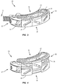
- Intervertebral implant 20 comprises an endplate 22, an opposite endplate 24 and a wedge 26 positioned between endplates 22, 24. Wedge 26 and portions of endplates 22, 24 are positioned within a frame 28 of implant 20, as discussed herein. Wedge 26 is configured to translate relative to endplates 22, 24 to move implant 20 between an undeployed or unexpanded configuration, shown in FIGS. 1 and 3 , and a deployed or expanded configuration, shown in FIGS. 2 and 4 .
- implant 20 is kidney-shaped and extends between an end 30 and an opposite end 32 along a radius, such as, for example an arc X, as shown in FIGS. 1 and 3 .
- a side 34 of implant 20 is convexly curved from end 30 to end 32 and an opposite side 36 of implant 20 is concavely curved from end 30 to end 32.
- arc X has a continuous radius of curvature.
- arc X has a variable radius of curvature.
- implant 20 is square, rectangular, oval, bullet-shaped, lordotic or kyphotic-shaped.
- implant 20 is made from one or more of the materials discussed herein.
- implant 20 is made from a metal, such as, for example, titanium.
- implant 20 consists of titanium or PEEK.
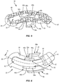
- Endplate 22 extends along arc X between an end 38 and an opposite end 40, as shown in FIGS. 5 and 6 .
- End 38 is positioned adjacent to end 30 of implant 20 and end 40 is positioned adjacent to end 32 of implant 20.
- Endplate 22 is curved along arc X.
- one side of endplate 22 is convexly curved between ends 38, 40 and an opposite side of endplate 22 is concavely curved between ends 38, 40.
- Endplate 22 comprises an engagement surface 42 configured to engage a first vertebra and an inner surface 44 opposite engagement surface 42. Inner surface 44 faces away from engagement surface 42.
- Endplate 22 comprises extensions 46, 48, 50 that extend from inner surface 44 such that extensions 46, 48, 50 each extend away from engagement surface 42.
- Extension 46 includes an extension 46a and an extension 46b that is spaced apart from extension 46a by an opening 52 that extends through engagement surface 42 and inner surface 44.
- Extension 48 includes an extension 48a and an extension 48b that is spaced apart from extension 48a such that extensions 46a, 46b are positioned between extensions 48a, 48b.
- Extension 50 extends across opening 52 from one side of endplate 22 to an opposite side of endplate 22.
- Extension 46a includes a planar portion 54a and a ramp 56a that extends from planar portion 54a.
- Extension 46b includes a planar portion 54b and a ramp 56b that extends from planar portion 54b.
- Ramps 56a, 56b are configured to slidably engage inclined portions of wedge 26 to move implant 20 between the unexpanded configuration shown in FIGS. 1 and 3 and the expanded configuration shown in FIGS. 2 and 4 , as discussed herein.
- planar portion 54a extends parallel or substantially parallel to planar portion 54b.
- planar portion 54a and planar portion 54b have the same pitch or a similar pitch, but different diameters such that planar portion 54b has a larger radius of curvature than planar portion 54a along arc X. As such, planar portion 54b has a length that is greater than that of planar portion 54a.
- planar portions 54a, 54b each extend parallel to engagement surface 42 and ramps 56a, 56b each extend transverse to engagement surface 42. In some embodiments, ramps 56a, 56b extend at an acute angle relative to engagement surface 42.
- planar portion 54b has a maximum length that is greater than a maximum length of planar portion 54a and ramp 56b has a maximum length that is greater than a maximum length of ramp 56a.
- planar portion 54a, planar portion 54b, ramp 56a and/or ramp 56b may be disposed at alternate orientations, relative to engagement surface 42, such as, for example, transverse, perpendicular and/or other angular orientations such as acute or obtuse, co-axial and/or may be offset or staggered.
- Extension 48a includes a slot 58a and extension 48b includes a slot 58b.
- Slots 58a, 58b each extend transverse to engagement surface 42.
- slot 58a extends parallel to slot 58b.
- slots 58a, 58b each extend parallel to ramp 56a and/or ramp 56b. Due to the curvature of endplate 22 along arc X, slot 58b has a maximum length that is greater than a maximum length of slot 58a, which allows engagement surface 42 to remain parallel to the engagement surface of endplate 24 as implant 20 moves between the unexpanded configuration and the expanded configuration, as discussed herein.
- Slots 58a, 58b each have an oblong configuration.
- slot 58a and/or slot 58b can be variously shaped, such as, for example, oval, triangular, square, polygonal, irregular, uniform, non-uniform, offset, staggered, undulating, arcuate, variable and/or tapered.
- slot 58a and/or slot 58b may be disposed at alternate orientations, relative to engagement surface 42, ramp 56a and/or ramp 56b, such as, for example, transverse, perpendicular and/or other angular orientations such as acute or obtuse, co-axial and/or may be offset or staggered.
- Extension 50 includes a planar portion 60 and a ramp 62 that extends from planar portion 60.
- Ramp 62 is configured to slidably engage inclined portions of wedge 26 to move implant 20 between the unexpanded configuration shown in FIGS. 1 and 3 and the expanded configuration shown in FIGS. 2 and 4 , as discussed herein.
- Planar portion 60 extends parallel to engagement surface 42, planar portion 54a and/or planar portion 54b.
- Ramp 62 extends parallel to ramp 56a and/or ramp 56b.
- planar portion 60 extends parallel to engagement surface 42 and ramp 62 extends transverse to engagement surface 42.
- ramp 62 extends at an acute angle relative to engagement surface 42.
- planar portion 60 and/or ramp 62 may be disposed at alternate orientations, relative to engagement surface 42, planar portion 54a, planar portion 54b, ramp 56a and/or ramp 56b, such as, for example, transverse, perpendicular and/or other angular orientations such as acute or obtuse, co-axial and/or may be offset or staggered.
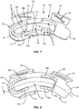
- Endplate 24 extends along arc X between an end 64 and an opposite end 66, as shown in FIGS. 7 and 8 .
- End 64 is positioned adjacent to end 30 of implant 20 and end 66 is positioned adjacent to end 32 of implant 20.
- Endplate 24 is curved along arc X.
- one side of endplate 24 is convexly curved between ends 64, 66 and an opposite side of endplate 24 is concavely curved between ends 64, 66.
- Endplate 24 comprises an engagement surface 68 configured to engage a second vertebra and an inner surface 70 opposite engagement surface 68. Inner surface 70 faces away from engagement surface 68.
- Endplate 24 comprises extensions 72, 74, 76, 78 that extend from inner surface 70 such that extensions 72, 74, 76, 78 each extend away from engagement surface 68.
- Extension 72 includes an extension 72a and an extension 72b that is spaced apart from extension 72a by an opening 80 that extends through engagement surface 68 and inner surface 70.
- Extension 74 includes an extension 74a and an extension 74b that is spaced apart from extension 74a such that extensions 72a, 72b are positioned between extensions 74a, 74b.
- Extension 76 includes an extension 76a and an extension 76b that is spaced apart from extension 76a by opening 80.
- Extension 78 is positioned adjacent to extension 76 such that extension 76b is positioned between extension 76a and extension 78.
- Extension 72a includes a ramp 82a and extension 72b includes a ramp 82b that is joined to ramp 82a by a planar portion 84 of extension 72.
- Ramps 82a, 82b are configured to slidably engage inclined portions of wedge 26 to move implant 20 between the unexpanded configuration shown in FIGS. 1 and 3 and the expanded configuration shown in FIGS. 2 and 4 , as discussed herein.
- Planar portion 84 extends parallel to engagement surface 68.
- Ramp 82a extends parallel to ramp 82b.
- planar portion 84 extends parallel to engagement surface 68 and ramps 82a, 82b each extend transverse to engagement surface 68.
- ramps 82a, 82b extend at an acute angle relative to engagement surface 68.
- ramp 82b has a maximum length that is greater than a maximum length of ramp 82a. This allows engagement surface 68 to remain parallel to engagement surface 42 of endplate 22 as implant 20 moves between the unexpanded configuration and the expanded configuration, as discussed herein.
- planar portion 84, ramp 82a and/or ramp 82b may be disposed at alternate orientations, relative to engagement surface 68, such as, for example, transverse, perpendicular and/or other angular orientations such as acute or obtuse, co-axial and/or may be offset or staggered.
- Extension 74a includes a slot 86a and extension 74b includes a slot 86b.
- Slots 86a, 86b each extend transverse to engagement surface 68. In some embodiments, slot 86a extends parallel to slot 86b. In some embodiments, slots 86a, 86b each extend parallel to ramp 82a and/or ramp 82b. Due to the curvature of endplate 24 along arc X, slot 86b has a maximum length that is greater than a maximum length of slot 86a, which allows engagement surface 68 to remain parallel to engagement surface 42 of endplate 22 as implant 20 moves between the unexpanded configuration and the expanded configuration, as discussed herein. Slots 86a, 86b each have an oblong configuration.
- slot 86a and/or slot 86b can be variously shaped, such as, for example, oval, triangular, square, polygonal, irregular, uniform, non-uniform, offset, staggered, undulating, arcuate, variable and/or tapered.
- slot 86a and/or slot 86b may be disposed at alternate orientations, relative to engagement surface 68, ramp 82a and/or ramp 82b, such as, for example, transverse, perpendicular and/or other angular orientations such as acute or obtuse, co-axial and/or may be offset or staggered.
- Extension 76a includes a planar portion 88a and a ramp 90a that extends from planar portion 88a.
- Extension 76b includes a planar portion 88b and a ramp 90b that extends from planar portion 88b.
- Ramps 90a, 90b are configured to slidably engage inclined portions of wedge 26 to move implant 20 between the unexpanded configuration shown in FIGS. 1 and 3 and the expanded configuration shown in FIGS. 2 and 4 , as discussed herein.
- Planar portion 88a extends parallel to planar portion 88b.
- Ramp 90a extends parallel to ramp 90b.
- planar portions 88a, 88b each extend parallel to engagement surface 68 and ramps 90a, 90b each extend transverse to engagement surface 68.
- ramps 90a, 90b extend at an acute angle relative to engagement surface 68.
- planar portion 88b has a maximum length that is greater than a maximum length of planar portion 88a and ramp 90b has a maximum length that is greater than a maximum length of ramp 90a.
- ramp 90a and/or ramp 90b extends parallel to ramp 82a and/or ramp 82b.
- planar portion 88a, planar portion 88b, ramp 90a and/or ramp 90b may be disposed at alternate orientations, relative to engagement surface 68, such as, for example, transverse, perpendicular and/or other angular orientations such as acute or obtuse, co-axial and/or may be offset or staggered.
- Extension 78 includes a slot 92 that extends transverse to engagement surface 68.
- slot 92 extends parallel to ramp 90a and/or ramp 90b.
- Slot 92 has an oblong configuration.
- slot 92 can be variously shaped, such as, for example, oval, triangular, square, polygonal, irregular, uniform, non-uniform, offset, staggered, undulating, arcuate, variable and/or tapered.
- slot 92 extends parallel to slot 86a and/or slot 86b.
- slot 92 may be disposed at alternate orientations, relative to engagement surface 68, ramp 90a and/or ramp 90b, such as, for example, transverse, perpendicular and/or other angular orientations such as acute or obtuse, co-axial and/or may be offset or staggered.
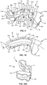
- Wedge 26 extends along arc X between an end 94 and an opposite end 96, as shown in FIGS. 9 and 10 .
- End 94 is positioned adjacent to end 30 of implant 20 and end 96 is positioned adjacent to end 32 of implant 20.
- Wedge 26 is curved along arc X.
- one side of wedge 26 is convexly curved between ends 94, 96 and an opposite side of wedge 26 is concavely curved between ends 94, 96.
- Wedge 26 includes a wall 98 having an upper surface 100 and a lower surface 102 opposite upper surface 100.
- Upper surface 100 includes spaced apart vertical portions 104a, 104b, horizontal portions 106a, 106b, 106c, 106d and inclined portions 108a, 108b.
- Vertical portion 104a is positioned between horizontal portion 106a and horizontal portion 106b.
- Inclined portion 108a is positioned between horizontal portion 106b and horizontal portion 106c.
- Inclined portion 108b is positioned between vertical portion 104b and horizontal portion 106d.
- Inclined portion 108a is configured to slidably engage ramp 56b and inclined portion 108b is configured to slidably engage ramp 62 as implant 20 moves between the unexpanded configuration and the expanded configuration, as discussed herein.
- Vertical portions 104a, 104b extend parallel to one another.
- Horizontal portions 106a, 106b, 106c, 106d extend parallel to one another. Horizontal portions 106a, 106b, 106c, 106d extend transverse to vertical portions 104a, 104b. In some embodiments, horizontal portions 106a, 106b, 106c, 106d extend perpendicular to vertical portions 104a, 104b. Inclined portions 108a, 108b each extend transverse to vertical portions 104a, 104b and transverse to horizontal portions 106a, 106b, 106c, 106d. In some embodiments, inclined portions 108a, 108b extend parallel to one another. In some embodiments, inclined portion 108a extends transverse to inclined portion 108b.
- Upper surface 100 includes spaced apart vertical portions 110a, 110b, horizontal portions 112a, 112b and inclined portions 114a, 114b.
- Vertical portion 110a is positioned between horizontal portion 106a and horizontal portion 112a.
- Inclined portion 114a is positioned between horizontal portion 112a and horizontal portion 112b.
- Inclined portion 114b is positioned between vertical portion 110b and horizontal portion 106d.
- Inclined portion 114a is configured to slidably engage ramp 56a and inclined portion 114b is configured to slidably engage ramp 62 as implant 20 moves between the unexpanded configuration and the expanded configuration, as discussed herein.
- Vertical portions 110a, 110b extend parallel to one another.
- vertical portions 110a, 110b extend parallel to vertical portions 104a, 104b.
- Horizontal portions 112a, 112b extend parallel to one another.
- horizontal portions 112a, 112b extend parallel to horizontal portions 106a, 106b, 106c, 106d.
- Horizontal portions 112a, 112b extend transverse to vertical portions 110a, 110b.
- horizontal portions 112a, 112b extend perpendicular to vertical portions 110a, 110b.
- Inclined portions 114a, 114b each extend transverse to vertical portions 110a, 110b and transverse to horizontal portions 112a, 112b.
- inclined portion 114a extends parallel to inclined portion 108a and inclined portion 114b extends parallel to inclined portion 108b. In some embodiments, inclined portions 114a, 114b extend parallel to one another. In some embodiments, inclined portion 114a extends transverse to inclined portion 114b.
- inclined portion 108a has a maximum length that is greater than a maximum length of inclined portion 114a and inclined portion 108b has a maximum length that is greater than a maximum length of inclined portion 114b.
- horizontal portion 106b has a maximum length that is greater than a maximum length of horizontal portion 112a and horizontal portion 106c has a maximum length that is greater than a maximum length of horizontal portion 112b.
- Lower surface 102 includes spaced apart inclined portions 116a, 116b, horizontal portions 118a, 118b, 118c and a vertical portion 120.
- Horizontal portion 118a is positioned between inclined portion 116a and vertical portion 120.
- Horizontal portion 118b is positioned between vertical portion 120 and inclined portion 116b.
- Inclined portion 116b is positioned between horizontal portion 118b and horizontal portion 118c.
- Inclined portion 116a is configured to slidably engage ramp 82b and inclined portion 116b is configured to slidably engage ramp 90b as implant 20 moves between the unexpanded configuration and the expanded configuration, as discussed herein.
- Vertical portion 120 extends parallel to vertical portions 104a, 104b and/or vertical portions 110a, 110b.
- Horizontal portions 118a, 118b, 118c extend parallel to one another. In some embodiments, horizontal portions 118a, 118b, 118c extend parallel to horizontal portions 106a, 106b, 106c, 106d and/or horizontal portions 112a, 112b. Horizontal portions 118a, 118b, 118c extend transverse to vertical portion 120. In some embodiments, horizontal portions 118a, 118b, 118c extend perpendicular to vertical portion 120. Inclined portions 116a, 116b each extend transverse to vertical portion 120 and transverse to horizontal portions 118a, 118b, 118c. In some embodiments, inclined portions 116a, 116b extend parallel to one another. In some embodiments, inclined portion 116a extends transverse to inclined portion 116b.
- Lower surface 102 includes spaced apart inclined portions 122a, 122b, horizontal portions 124a, 124b, 124c and a vertical portion 126.
- Horizontal portion 124a is positioned between inclined portion 122a and vertical portion 126.
- Horizontal portion 124b is positioned between vertical portion 126 and inclined portion 122b.
- Inclined portion 122b is positioned between horizontal portion 124b and horizontal portion 124c.
- Inclined portion 122a is configured to slidably engage ramp 82a and inclined portion 122b is configured to slidably engage ramp 90a as implant 20 moves between the unexpanded configuration and the expanded configuration, as discussed herein.
- Vertical portion 126 extends parallel to vertical portion 120, vertical portions 104a, 104b and/or vertical portions 110a, 110b.
- Horizontal portions 124a, 124b, 124c extend parallel to one another.
- horizontal portions 124a, 124b, 124c extend parallel to horizontal portions 118a, 118b, 118c, horizontal portions 106a, 106b, 106c, 106d and/or horizontal portions 112a, 112b.
- Horizontal portions 124a, 124b, 124c extend transverse to vertical portion 126.
- horizontal portions 124a, 124b, 124c extend perpendicular to vertical portion 126.
- Inclined portions 122a, 122b each extend transverse to vertical portion 126 and transverse to horizontal portions 124a, 124b, 124c. In some embodiments, inclined portions 122a, 122b extend parallel to one another. In some embodiments, inclined portion 122a extends transverse to inclined portion 122b. In some embodiments, inclined portion 122a extends parallel to inclined portion 116a and inclined portion 122b extends parallel to inclined portion 116b.
- inclined portion 116a has a maximum length that is greater than a maximum length of inclined portion 122a and inclined portion 116b has a maximum length that is greater than a maximum length of inclined portion 122b.
- horizontal portion 118b has a maximum length that is greater than a maximum length of horizontal portion 124b and horizontal portion 118a has a maximum length that is greater than a maximum length of horizontal portion 124a.
- Wedge 26 includes a cavity 128.
- cavity 128 When implant 20 is assembled, cavity 128 is in communication with openings 52, 80 such that a material, such as, for example, bone graft material, can be inserted through opening 52 and/or opening 80 and into cavity 128.
- Cavity 128 separates horizontal portion 106b from horizontal portion 112a, inclined portion 108a from inclined portion 114a, horizontal portion 106c from horizontal portion 112b, vertical portion 104a from vertical portion 110a, vertical portion 104b from vertical portion 110b and inclined portion 108b from inclined portion 114b.
- Cavity 128 also separates inclined portion 116a from inclined portion 122a, horizontal portion 118a from horizontal portion 124a, vertical portion 120 from vertical portion 126, horizontal portion 118b from horizontal portion 124b, inclined portion 116b from inclined portion 122b and horizontal portion 118c from horizontal portion 124c.
- Wedge 26 comprises a plurality of apertures that extend through wall 98.
- wedge 26 comprises an aperture 130a that extends through wall 98 between horizontal portions 106b, 118a; an aperture 130b that extends through wall 98 between horizontal portions 112a, 124a; an aperture 130c that extends through wall 98 between horizontal portions 106c, 118b; an aperture 130d that extends through wall 98 between horizontal portions 112b, 124b; an aperture 130e that extends through wall 98 between inclined portion 108b and horizontal portion 118c; and an aperture 130f that extends through wall 98 between inclined portion 114b and horizontal portion 124c.
- Aperture 130a is coaxial with aperture 130b; aperture 130c is coaxial with aperture 130d; and aperture 130e is coaxial with aperture 130f.
- apertures 130a, 130b are aligned with slots 86a, 86b of endplate 24 such that a pin extends through apertures 130a, 130b and slots 86a, 86b, as discussed herein;
- apertures 130c, 130d are aligned with slots 58a, 58b of endplate 22 such that a pin extends through apertures 130c, 130d and slots 58a, 58b, as discussed herein;
- apertures 130e, 130f are aligned with slot 92 of endplate 24 such that a pin extends through apertures 130e, 130f and slot 92, as discussed herein.
- End 96 of wedge 26 comprises an enlarged end wall 132, as shown in FIG. 10A .
- Wall 132 has a maximum width that is greater than a maximum width of end 94 and/or wall 98.
- An inner surface of wall 132 defines an arcuate trough 134.
- Trough 134 is configured for disposal of an actuator of implant 20, as discussed herein.
- trough 134 has a continuous radius of curvature from a first end of trough 134 to a second end of trough 134.
- trough 134 has a variable radius of curvature from the first end of trough 134 to the second end of trough 134.
- Frame 28 extends between an end 136 and an opposite end 138, as shown in FIGS. 11 and 12 .
- End 136 is positioned adjacent to end 30 of implant 20 and end 138 is positioned adjacent to end 32 of implant 20.
- Frame 28 is curved along arc X between end 136 and end 138.
- Frame 28 includes a wall 140 having an inner surface that defines an interior cavity 142. Wedge 26 and at least a portion of each of endplates 22, 24 are positioned within interior cavity 142.
- End 138 of frame 28 includes an upper wall 143 and a lower wall 144.
- Upper wall 143 is spaced apart from lower wall 144 to define a recess 148 between upper wall 143 and lower wall 144.
- Recess 148 is configured for disposal of a pivot 150, as discussed herein.
- Upper wall 143 includes an opening 152 that is aligned with an opening 154 in lower wall 144. Openings 152, 154 are each configured for disposal of a pivot plug to couple pivot 150 to frame 28, as discussed herein. In some embodiments, opening 152 is coaxial with opening 154.
- Pivot 150 includes an upper surface 156 and a lower surface 158 opposite upper surface 156, as shown in FIGS. 13 and 14 .
- Pivot 150 includes a ring 160 that extends from upper surface 156 and a ring 162 that extends from lower surface 158. Rings 160, 162 are aligned with one another such that ring 160 is coaxial with ring 162. Rings 160, 162 each have an inner diameter that is equivalent to opening 152 and/or opening 154.
- ring 160 When pivot 150 is positioned within recess 148, ring 160 is aligned with opening 152 such that a plug, such as, for example, a pivot plug 164 extends through opening 152 and into ring 160, and ring 162 is aligned with opening 154 such that a plug, such as, for example, a pivot plug 166 extends through opening 154 and into ring 162 to couple pivot 150 to frame 28, as discussed herein.
- Pivot 150 includes a threaded passageway 168 and a threaded passageway 170 that are spaced apart from passageway 168 by a wall 172.
- Passageways 168, 170 are each configured for disposal of an insertion tool and/or an actuator 174 of implant 20.
- the insertion tool may be used to insert implant 20 between adjacent vertebrae, for example.
- Actuator 174 includes a threaded shaft 176 and a ball-shaped tip 178 attached to shaft 176, as shown in FIG. 15 , for example.
- Tip 178 is positioned within trough 134 of wedge 26 and shaft 176 is positioned within passageway 168 or passageway 170 such that the threads on shaft 176 engage threads of passageway 168 or threads of passageway 170.
- shaft 176 includes a socket that is configured to mate with a bit of a driver such that the bit of the driver can be inserted within the socket to rotate actuator 174 relative to pivot 150.
- the socket may have a cruciform, Phillips, square, hexagonal, polygonal, star or hexalobe cross sectional configuration. It is envisioned that the socket may have any configuration that allows the tip of the driver to mate with the socket such that rotation of the driver rotates actuator 174.
- Through holes and slots could be provided in the components described to allow injection of graft material from outside the interbody device into opening 52, opening 80 and/or cavity 128 to promote fusion.
- the graft material could be transported from outside the incision into opening 52, opening 80 and/or cavity 128, or could be loaded at some intermediary holding chamber, possibly within the inserter midway into the incision, to then be injected or passed into opening 52, opening 80 and/or cavity 128.
- One specific example might be providing a loading tube integral to the actuator driver which would then flow into a central hole in actuator 174, then into the common cavity of endplate 22, endplate 24 and wedge 26.
- the graft material would flow into the common cavity, then ports provided in an outer wall of implant 20 to allow the graft to flow into the interbody space.
- Anchoring features may also be included to allow flow from outside implant 20 into the disc space directly, bypassing implant 20 altogether.
- Implant 20 may be assembled by positioning wedge 26 through recess 148 of frame 28 such that end 94 of wedge 26 is positioned within cavity 142 of frame 28, as shown in FIG. 16 .
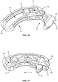
- Wedge 26 is translated relative to frame 28 in the direction shown by arrow A in FIG. 17 such that end 94 of wedge 26 is positioned within cavity 142 of frame 28 and wall 132 of wedge 26 is positioned within recess 148 of frame 28 such that an arcuate cutout 180 of wedge 26 is aligned with openings 152, 154, as shown in FIG. 17 .
- End 94 of wedge 26 is positioned entirely within cavity 142 such that end 94 is surrounded by wall 140 of frame 28.
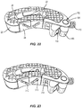
- Endplate 24 is coupled to frame 28 by positioning wall 140 of frame 28 between extensions 72a, 74a of endplate 24, between extensions 72b, 74b of endplate 24 and between extensions 76b, 78 of endplate 24, as shown in FIG. 18 .
- An axial surface 182 of extension 74a engages a flange 184 of frame 28; an axial surface 186 of extension 74b engages a flange 188 of frame 28; and an axial surface 190 of extension 78 engages a flange 192 of frame 28.
- Endplate 24 is positioned relative to wedge 26 such that inclined portion 116a of wedge 26 engages ramp 82b of endplate 24, inclined portion 122a of wedge 26 engages ramp 82a of endplate 24, horizontal portions 118a, 124a of wedge 26 engage inner surface 70 of endplate 24, horizontal portion 118b of wedge 26 engages planar portion 88b of endplate 24, horizontal portion 124b of wedge 26 engages planar portion 88a of endplate 24, inclined portion 116b of wedge 26 engages ramp 90b of endplate 24 and inclined portion 122b of wedge 26 engages ramp 90a of endplate 24.
- Endplate 22 is coupled to frame 28 by positioning wall 140 of frame 28 between extensions 46a, 48a of endplate 22 and between extensions 46b, 48b of endplate 22.
- Endplate 22 is positioned relative to endplate 24 such that an axial surface 194 of extension 48a engages an axial surface 196 of extension 74a and an opposite axial surface 198 of extension 48a engages a flange 200 of frame 28.
- an axial surface 202 of extension 48b engages an axial surface 204 of extension 74b, and an opposite axial surface 206 of extension 48b engages a flange 208 of frame 28.
- Endplate 22 is coupled to wedge 26 such that planar portion 54a of endplate 22 engages horizontal portion 112a, planar portion 54b of endplate 22 engages horizontal portion 106b of wedge 26, ramp 56a of endplate 22 engages inclined portion 108a of wedge 26, ramp 56b of endplate 22 engages inclined portion 114a of wedge 26 and ramp 62 of endplate 22 engages inclined portions 108b, 114b of wedge 26.
- Actuator 174 is coupled to pivot 150 by inserting shaft 176 of actuator 174 into one of passageways 168, 170 such that threads on shaft 176 engage the threads of one of passageways 168, 170, as shown in FIG. 20 .
- Tip 178 of actuator 174 is positioned within trough 134 of wedge 26 and pivot 150 is positioned within recess 148 of frame 28 such that ring 160 of pivot 150 is aligned with opening 152 of frame 28, and ring 162 of pivot 150 is aligned with opening 154 of frame 28, as shown in FIG. 21 .
- pivot plug 164 is positioned through opening 152 of frame 28 and into ring 160 of pivot 150 and pivot plug 166 is positioned through opening 154 of frame 28 and into ring 162 of pivot 150 to couple pivot 150 to frame 28 such that pivot 150 is pivotable relative to frame 28 about rings 160, 162 and/or pivot plugs 164, 166.
- a first pin 210 is positioned through apertures 130a, 130b of wedge 26 and slots 86a, 86b of endplate 24, as shown in FIG. 23 .
- a second pin 212 is positioned through apertures 130c, 130d of wedge 26 and slots 58a, 58b of endplate 22.
- a third pin 214 is positioned through apertures 130e, 130f of wedge 26 and slot 92 of endplate 24.
- the interbody implant system is employed with a surgical procedure, such as, a fusion treatment of a spine of a patient including vertebrae and body areas adjacent thereto, as discussed herein.
- the interbody implant system may also be employed with other surgical procedures, such as, for example, discectomy, laminotomy, laminectomy, nerve-root retraction, foramenotomy, facetectomy, decompression, and spinal, nucleus or disc replacement.
- the interbody implant system can be employed with a surgical arthrodesis procedure, such as, for example, an interbody fusion for treatment of an applicable condition or injury of an affected section of a spinal column and adjacent areas within a body, such as, for example, an intervertebral disc space between a first vertebra and a second vertebra.
- a surgical arthrodesis procedure such as, for example, an interbody fusion for treatment of an applicable condition or injury of an affected section of a spinal column and adjacent areas within a body, such as, for example, an intervertebral disc space between a first vertebra and a second vertebra.
- intervertebral implant 20 of the interbody implant system described above, can be inserted within the intervertebral disc space to space apart articular joint surfaces, provide support and maximize stabilization of the vertebrae.
- intervertebral implant 20 provides height restoration between vertebral bodies, decompression, restoration of sagittal balance and/or resistance of subsidence into vertebral endplates.
- interbody implant system can be used in any existing surgical method or technique including open surgery, mini-open surgery, minimally invasive surgery and percutaneous surgical implantation, whereby the vertebrae are accessed through a mini-incision or sleeve that provides a protected passageway to the area.
- Intervertebral implant 20, described above is then employed to augment the surgical treatment.
- Intervertebral implant 20 can be delivered or implanted as a pre-assembled device or can be assembled in situ.
- Intervertebral implant 20 can be completely or partially revised, removed or replaced in situ. It is contemplated that one or all of the components of the interbody implant system can be delivered to the surgical site via manual manipulation and/or a free hand technique. It is further contemplated that intervertebral implant 20 may be inserted posteriorly, and then manipulated anteriorly and/or lateral and/or medial.
- a cutting instrument creates a surgical pathway for implantation of intervertebral implant 20 within the patient's body.
- a guide instrument (not shown) is employed to initially distract the first vertebra from the second vertebra.
- a sleeve or cannula is used to access the intervertebral disc space and facilitate delivery and access for components of the interbody implant system.
- a preparation instrument can be inserted within the sleeve or cannula and disposed within the intervertebral disc space.
- the preparation instrument(s) can be employed to remove some or all of the disc tissue including the disc nucleus and fluids, adjacent tissues and/or bone, corticate, scrape and/or remove tissue from the surfaces of endplates of the first and second vertebrae, as well as for aspiration and irrigation of the region according to the requirements of a particular surgical application.
- Intervertebral implant 20 is inserted into the patient with implant 20 disposed in the unexpanded configuration shown in FIGS. 1 and 3 .
- Implant 20 is delivered along the surgical pathway using a substantially posterior approach to position implant 20 within the intervertebral disc space.
- an end of an inserter is positioned within passageway 168 or passageway 170 of pivot 150 to couple implant 20 with the inserter.
- the end of the inserter includes a threaded tip that mates with threads of passageway 168 or passageway 170 of pivot 150 to couple implant 20 with the inserter.
- the inserter is then manipulated to deliver implant 20 into the prepared intervertebral disc space, between the first vertebra and the second vertebra, according to the requirements of a particular surgical application.
- implant 20 may be moved within the intervertebral disc space such that implant 20 is positioned within the intervertebral disc space at a selected angle by moving pivot 150 such that pivot 150 rotates relative to endplates 22, 24, wedge 26 and frame 28. That is, implant 20 may be rotated within the intervertebral disc space by articulating pivot 150 to rotate pivot 150 relative to endplates 22, 24, wedge 26 and frame 28. In some embodiments, pivot 150 is rotated relative to endplates 22, 24, wedge 26 and frame 28 by manipulating the inserter. For example, the inserter may be used to pivot endplates 22, 24, wedge 26 and frame 28 relative to pivot 150 from a first angle shown in FIG. 24 to a second angle shown in FIG. 25 .
- the difference between the first and second angles is between about 15 degrees and about 85 degrees.
- pivot 150 is articulated relative to endplates 22, 24, wedge 26 and frame 28 such that implant 20 is disposed at a selected angle relative to the inserter before positioning implant 20 within the intervertebral disc space.
- Implant 20 is then inserted into the intervertebral disc space with implant 20 at the selected angle relative to the inserter to position implant 20 at a selected angle within the intervertebral disc space.
- the inserter can be uncoupled from implant 20 by rotating the inserter relative to pivot 150 such that the threaded tip of the inserter backs out of passageway 168 or passageway 170 of pivot 150.
- intervertebral implant 20 Upon desired positioning of intervertebral implant 20 within the intervertebral disc space, the tip of the driver is inserted into a socket of shaft 176 of actuator 174 to mate features of the tip of the driver with features of the socket of shaft 176 such that rotation of the driver rotates actuator 174 relative to pivot 150. Implant 20 is then deployed within the intervertebral disc space to move implant 20 from the unexpanded configuration, shown in FIGS. 1 and 3 , to the expanded configuration, shown in FIGS. 2 and 4 . The driver is rotated in a first rotational direction, such as, for example, clockwise or counterclockwise such that actuator 174 moves relative to pivot 150 in the direction shown by arrow D in FIG. 1 .
- a first rotational direction such as, for example, clockwise or counterclockwise
- tip 178 of actuator 174 pushes against the inner surface of end wall 132 that defines trough 134 of wedge 26 such that wedge 26 moves relative to endplates 22, 24 and frame 28 in the direction shown by arrow D.
- Pin 210 remains positioned within apertures 130a, 130b of wedge 26 and translates within slots 86a, 86b of endplate 24 as implant 20 moves from the unexpanded configuration to the expanded configuration. That is, pin 210 moves from one end of each of slots 86a, 86b to an opposite end of slots 86a, 86b as implant 20 moves from the unexpanded configuration to the expanded configuration.
- Pin 212 remains positioned within apertures 130c, 130d of wedge 26 and translates within slots 58a, 58b of endplate 22 as implant 20 moves from the unexpanded configuration to the expanded configuration.
- pin 212 moves from one end of each of slots 58a, 58b to an opposite end of slots 58a, 58b as implant 20 moves from the unexpanded configuration to the expanded configuration.
- Pin 214 remains positioned within apertures 130e, 130f of wedge 26 and translates within slot 92 of endplate 24 as implant 20 moves from the unexpanded configuration to the expanded configuration. That is, pin 214 moves from one end of slot 92 to an opposite end of slot 92 as implant 20 moves from the unexpanded configuration to the expanded configuration.
- Engagement surface 42 of endplate 22 is spaced apart a first distance from engagement surface 68 of endplate 24 when implant 20 is the unexpanded configuration. Engagement surface 42 is spaced apart an increased second distance from engagement surface 68 when implant 20 is in the expanded configuration, shown in FIGS. 2 and 4 .
- the first distance is about 7 mm and the second distance is at least about 14 mm. In some embodiments, the first distance is about 8 mm and the second distance is at least about 16 mm. In some embodiments, the first distance is about 9 mm and the second distance is at least about 18 mm.
- endplate 22 moves away from endplate 24 such that engagement surface 42 of endplate 22 engages the first vertebra and engagement surface 68 of endplate 24 engages the second vertebra. That is, endplate 22 moves relative to frame 28 in the direction shown by arrow B in FIG. 19 and endplate 24 moves relative to frame 28 in the direction shown by arrow C in FIG. 19 .
- endplates 22, 24 move in the directions shown by arrows B and C, endplate 22 does not translate axially relative to endplate 24 and/or frame 28 and endplate 24 does not translate axially relative to endplate 22 and/or frame 28. That is, endplate 22 does not translate relative to endplate 24 and/or frame 28 in the direction shown by arrow E in FIG.
- endplate 24 does not translate relative to endplate 22 and/or frame 28 in the direction shown by arrow E in FIG. 19 or the direction shown by arrow F in FIG. 19 as endplate 24 moves relative to frame 28 in the direction shown by arrow C in FIG. 19 .
- intervertebral implant 20 provides height restoration between the first vertebra and the second vertebra, decompression, restoration of sagittal balance and resistance of subsidence into the endplates of the vertebrae.
- Implant 20 may be kept in the expanded configuration to maintain the increased size of the intervertebral disc space.
- a material such as, for example, bone graft is positioned within cavity 128 of wedge 26 to promote bone growth to fuse the first vertebra with the second vertebra.
- the material is inserted through opening 52 of endplate 22 and into cavity 128.
- the material is inserted through opening 80 of endplate 24 and into cavity 128. In some embodiments, the material is inserted into cavity 128 through an aperture or other opening in one or more of endplates 22, 24 and frame 28, such as, for example, one or more of slots 58a, 58b, 86a, 86b, 92.
- engagement surface 42 extends parallel to engagement surface 68 when implant 20 is in the expanded configuration. In some embodiments, engagement surface 42 extends transverse to engagement surface 68 when implant 20 is in the expanded configuration. It is envisioned that the ramps/inclined portions of endplates 22, 24 and wedge 26 can be configured such that engagement surface 42 extends at any angle between about 0 degrees and about 90 degrees relative to engagement surface 68 when implant 20 is in the expanded configuration.
- the bone graft can be a particulate material, which may include an osteoconductive material such as HA and/or an osteoinductive agent such as a bone morphogenic protein (BMP) to enhance bony fixation of intervertebral implant 20 with the adjacent vertebrae. It is contemplated that the bone graft may include therapeutic polynucleotides or polypeptides.
- an osteoconductive material such as HA
- an osteoinductive agent such as a bone morphogenic protein (BMP) to enhance bony fixation of intervertebral implant 20 with the adjacent vertebrae.
- BMP bone morphogenic protein
- the agent and/or bone graft may include biocompatible materials, such as, for example, biocompatible metals and/or rigid polymers, such as, titanium elements, metal powders of titanium or titanium compositions, sterile bone materials, such as allograft or xenograft materials, synthetic bone materials such as coral and calcium compositions, such as HA, calcium phosphate and calcium sulfite, biologically active agents, for example, gradual release compositions such as by blending in a bioresorbable polymer that releases the biologically active agent or agents in an appropriate time dependent fashion as the polymer degrades within the patient.
- Suitable biologically active agents include, for example, BMP, Growth and Differentiation Factors proteins (GDF) and cytokines.
- Implant 20 can be made of radiolucent materials such as polymers. Radiomarkers may be included for identification under x-ray, fluoroscopy, CT or other imaging techniques. It is envisioned that the bone graft may include one or a plurality of therapeutic agents and/or pharmacological agents for release, including sustained release, to treat, for example, pain, inflammation and degeneration.
- intervertebral implant 20 is delivered through the surgical pathway along a transforaminal lumbar interbody fusion approach into the intervertebral disc space and disposed in the deployed or expanded configuration.
- a plurality of intervertebral implants 20 are delivered through the surgical pathway along a posterior lumbar interbody fusion approach into the intervertebral disc space and disposed in the deployed or expanded configuration in a side by side orientation.
- intervertebral implant 20 can be collapsed from the expanded configuration to an alternate configuration between the expanded configuration and the unexpanded configuration to collapse intervertebral implant 20 as may be desired to reposition with or remove intervertebral implant 20 from the intervertebral disc space.
- the interbody implant system includes a plurality of intervertebral implants 20, which can be variously sized and configured, and/or oriented in a side by side engagement, spaced apart and/or staggered.
- Implant 20 may be moved from the expanded configuration to the unexpanded configuration by rotating the driver in a second rotational direction, such as, for example, clockwise or counterclockwise such that actuator 174 moves relative to pivot 150 in the direction shown by arrow G in FIG. 1 .
- a second rotational direction such as, for example, clockwise or counterclockwise
- tip 178 of actuator 174 pulls end wall 132 of wedge 26 in the direction shown by arrow F in FIG. 19 such that wedge 26 moves relative to endplates 22, 24 and frame 28 in the direction shown by arrow F.
- Pin 210 remains positioned within apertures 130a, 130b of wedge 26 and translates within slots 86a, 86b of endplate 24 as implant 20 moves from the expanded configuration to the unexpanded configuration. That is, pin 210 moves from one end of each of slots 86a, 86b to an opposite end of slots 86a, 86b as implant 20 moves from the expanded configuration to the unexpanded configuration.
- Pin 212 remains positioned within apertures 130c, 130d of wedge 26 and translates within slots 58a, 58b of endplate 22 as implant 20 moves from the expanded configuration to the unexpanded configuration.
- pin 212 moves from one end of each of slots 58a, 58b to an opposite end of slots 58a, 58b as implant 20 moves from the expanded configuration to the unexpanded configuration.
- Pin 214 remains positioned within apertures 130e, 130f of wedge 26 and translates within slot 92 of endplate 24 as implant 20 moves from the expanded configuration to the unexpanded configuration. That is, pin 214 moves from one end of slot 92 to an opposite end of slot 92 as implant 20 moves from the expanded configuration to the unexpanded configuration.
- a device to space apart vertebral members comprising: a first endplate comprising a first engagement surface and first and second extensions that each extend away from the first engagement surface, the first extension comprising a first ramp and the second extension comprising a first slot; a second endplate comprising a second engagement surface and third and fourth extensions that each extend away from the second engagement surface, the third extension comprising a second ramp and the fourth extension comprising a second slot; a wedge positioned between the endplates, the wedge comprising an upper surface having a first inclined portion that slidably engages the first ramp and a lower surface having a second inclined portion that slidably engages the second ramp, the wedge comprising first and second apertures; a first pin extending through the first aperture and the first slot; and a second pin extending through the second aperture and the second slot, wherein the wedge is movable relative to the endplates to move the device between a first configuration having a first height between the engagement surfaces and a second configuration having an increased
- a device to space apart vertebral members comprising: a first endplate comprising a first engagement surface and first and second extensions that each extend away from the first engagement surface, the first extension comprising a first ramp and the second extension comprising a first slot, the first ramp extending transverse to the first engagement surface and parallel to the first slot; a second endplate comprising a second engagement surface and third and fourth extensions that each extend away from the second engagement surface, the third extension comprising a second ramp and the fourth extension comprising a second slot, the second ramp extending transverse to the second engagement surface and parallel to the second slot; a wedge positioned between the endplates, the wedge comprising an upper surface having a first inclined portion that slidably engages the first ramp and a lower surface having a second inclined portion that slidably engages the second ramp, the wedge comprising first and second apertures; a frame having an interior cavity, the ramps and the wedge being positioned within the interior cavity; a pivot coupled to the frame; an actuator that
Landscapes
- Health & Medical Sciences (AREA)
- Engineering & Computer Science (AREA)
- Biomedical Technology (AREA)
- Orthopedic Medicine & Surgery (AREA)
- Neurology (AREA)
- Heart & Thoracic Surgery (AREA)
- Oral & Maxillofacial Surgery (AREA)
- Transplantation (AREA)
- Cardiology (AREA)
- Vascular Medicine (AREA)
- Life Sciences & Earth Sciences (AREA)
- Animal Behavior & Ethology (AREA)
- General Health & Medical Sciences (AREA)
- Public Health (AREA)
- Veterinary Medicine (AREA)
- Prostheses (AREA)
Abstract
Description
- The present disclosure generally relates to medical devices, systems and methods for the treatment of musculoskeletal disorders, and more particularly to an expandable interbody implant system and method for treating a vertebral column.
- Spinal disorders such as degenerative disc disease, disc herniation, osteoporosis, spondylolisthesis, stenosis, scoliosis and other curvature abnormalities, kyphosis, tumor, and fracture may result from factors including trauma, disease and degenerative conditions caused by injury and aging. Spinal disorders typically result in symptoms including pain, nerve damage, and partial or complete loss of mobility. For example, after a disc collapse, severe pain and discomfort can occur due to the pressure exerted on nerves and the spinal column.
- Non-surgical treatments, such as medication, rehabilitation and exercise can be effective, however, may fail to relieve the symptoms associated with these disorders. Surgical treatment of these spinal disorders includes fusion, fixation, discectomy, laminectomy and implantable prosthetics. These treatments may employ interbody implants. This disclosure describes an improvement over these prior art technologies.
- Accordingly, an expandable interbody implant system and method are disclosed. In one embodiment, the system includes a device to space apart vertebral members. The device comprises a first endplate comprising a first engagement surface and first and second extensions that each extend away from the first engagement surface. The first extension comprises a first ramp and the second extension comprises a first slot. A second endplate comprises a second engagement surface and third and fourth extensions that each extend away from the second engagement surface. The third extension comprises a second ramp and the fourth extension comprises a second slot. A wedge is positioned between the endplates. The wedge comprises an upper surface having a first inclined portion that slidably engages the first ramp and a lower surface having a second inclined portion that slidably engages the second ramp. The wedge comprises first and second apertures. A first pin extends through the first aperture and the first slot. A second pin extends through the second aperture and the second slot. The wedge is movable relative to the endplates to move the device between a first configuration having a first height between the engagement surfaces and a second configuration having an increased second height between the engagement surfaces.
- The present disclosure will become more readily apparent from the specific description accompanied by the following drawings, in which:
-
FIG. 1 is a perspective view of one embodiment of an implant of a system in accordance with the principles of the present disclosure; -
FIG. 2 is a perspective view of the implant shown inFIG. 1 ; -
FIG. 3 is a perspective view of the implant shown inFIG. 1 ; -
FIG. 4 is a perspective view of the implant shown inFIG. 1 ; -
FIG. 5 is a top, perspective view of a component of the implant shown inFIG. 1 ; -
FIG. 6 is a bottom view of a component of the implant shown inFIG. 1 ; -
FIG. 7 is a top, perspective view of a component of the implant shown inFIG. 1 ; -
FIG. 8 is a top view of a component of the implant shown inFIG. 1 ; -
FIG. 9 is a top, perspective view of a component of the implant shown inFIG. 1 ; -
FIG. 10 is a top view of a component of the implant shown inFIG. 1 ; -
FIG. 10A is an end, perspective view of a component of the implant shown inFIG. 1 ; -
FIG. 11 is a top, perspective view of a component of the implant shown inFIG. 1 ; -
FIG. 12 is a top view of a component of the implant shown inFIG. 1 ; -
FIG. 13 is a top, perspective view of a component of the implant shown inFIG. 1 ; -
FIG. 14 is a bottom, perspective view of a component of the implant shown inFIG. 1 ; -
FIG. 15 is a side view of a component of the implant shown inFIG. 1 ; -
FIG. 16 is a top, perspective view of components of the implant shown inFIG. 1 ; -
FIG. 17 is a top, perspective view of components of the implant shown inFIG. 1 ; -
FIG. 18 is a top, perspective view of components of the implant shown inFIG. 1 ; -
FIG. 19 is a top, perspective view of components of the implant shown inFIG. 1 ; -
FIG. 20 is a top, perspective view of components of the implant shown inFIG. 1 ; -
FIG. 21 is a top, perspective view of components of the implant shown inFIG. 1 ; -
FIG. 22 is a top, perspective view of components of the implant shown inFIG. 1 ; -
FIG. 23 is a top, perspective view of components of the implant shown inFIG. 1 ; -
FIG. 24 is a top view of the implant shown inFIG. 1 ; and -
FIG. 25 is a top view of the implant shown inFIG. 1 . - The exemplary embodiments of an expandable interbody implant system and related methods of use disclosed herein are discussed in terms of medical devices for the treatment of musculoskeletal disorders and more particularly, in terms of an expandable interbody implant system and related methods for treating a vertebral column. It is envisioned that the implant system may provide, for example, fusion, decompression, restoration of sagittal balance and resistance of subsidence into tissue, such as, for example, surfaces of vertebral endplates. It is further envisioned that the system includes an interbody implant that expands after insertion into an intervertebral disc space and has several features, such as, for example, facile insertion into the intervertebral disc space such that less bone removal is necessary during a surgical procedure, decompression of nerve roots, and expansion to restore sagittal balance such that more expansion is provided on an anterior side relative to a posterior side in for example, a lumbar application. In some embodiments, the interbody implant can be inserted into the intervertebral disc space using a passive (e.g., non-steerable) or active (e.g., steerable) inserter. In some embodiments, the interbody implant is configured to be inserted at about a 15 degree angle and can be articulated about 85 degrees to about 100 degrees. This arrangement allows for continuous angulation, which allows implant deployment at any angle from about 15 through about 85-100 degrees. That is, the interbody implant is configured to be inserted at a starting angle of about 15 degrees with about 85-100 degrees of additional angulation. In some embodiments, articulation is achieved through the use of a pivot that is secured to a frame of the implant. In some embodiments, the pivot is secured to the frame using pivot plugs. In some embodiments, the interbody implant can be deployed at any insertion angle. In some embodiments, the interbody implant can be deployed at any angle from about 15 to about 85-90 degrees. In some embodiments, the expandable interbody implant has a 32 millimeter (mm) by 13.5 mm footprint. In some embodiments, the expandable interbody implant has a maximum insertion footprint of about 13.5 mm at 15 degrees.
- In some embodiments, the expandable interbody implant has an undeployed height and can be expanded to a deployed height. In some embodiments, the deployed height is less than twice the undeployed height. In some embodiments, the deployed height is twice the undeployed height. In some embodiments, the deployed height is greater than twice the undeployed height. In some embodiments, the expandable interbody implant has an undeployed height of about 7 mm and can be expanded to a deployed height of about 14 mm. In some embodiments, the expandable interbody implant has an undeployed height of about 8 mm and can be expanded to a deployed height of about 16 mm. In some embodiments, the expandable interbody implant has an undeployed height of about 9 mm and can be expanded to a deployed height of about 18 mm. In some embodiments, the expandable interbody implant has an undeployed height of about 10 mm and can be expanded to a deployed height of about 20 mm. In some embodiments, the expandable interbody implant is deployed using a drive screw to move the implant from the undeployed height to the deployed height. The drive screw threads into the pivot discussed herein. In some embodiments, the drive screw comprises a ball tip that is positioned in a circular or semi-circular trough in a wedge of the implant, wherein unscrewing the ball tipped screw retracts the wedge and undeploys the implant. In some embodiments, the expandable interbody implant may be incrementally deployed from the undeployed height to the deployed height.
- In some embodiments, the expandable interbody implant includes implant endplates, such as, for example, upper and lower implant endplates each having ramps that engage ramps (inclined portions) of the wedge. That is, each of the implant endplates include multiple ramps. The wedge includes an upper surface with multiple ramps that engage the ramps of the upper endplate and a lower surface with multiple ramps that engage the ramps of the lower endplate. The wedge moves relative to the endplates to move the ramps of the endplates along the ramps of the wedge to move the implant from the undeployed height to the deployed height. As the wedge moves away from the pivot, endplate deployment is achieved. The ramps are staggered such that opposing ramps are not aligned or mirrored. The relative position of the implant endplates with respect to the pivot is maintained by the frame. In some embodiments, the ramps of the implant endplate reside on the ramps of the wedge when the implant is fully deployed. In some embodiments, the ramps have asymmetrical geometry to allow the endplates to be driven into a parallel relationship. In some embodiments, the ramps have asymmetrical geometry to allow the endplates to be driven into a non-parallel relationship (kyphosis or lordosis). In some embodiments, the ramps have asymmetrical geometry to allow the endplates to simultaneously correct sagittal and coronal imbalance while restoring interbody height.
- In some embodiments, the expandable interbody implant is kidney shaped and defines a curve of radii X. The wedge travels along radii X as the implant moves between the undeployed and deployed heights. In some embodiments, all ramps, inclined portions, slots and other features converge to the center of radii X in order to function, while avoiding binding. In some embodiments, the radii can be infinity and the implant is a straight implant. In some embodiments, the expandable interbody implant is rectangular, bullet-shaped, lordotic or kyphotic-shaped.
- In some embodiments, the expandable interbody implant system is employed with a posterior approach to the intervertebral disc space. In some embodiments, the expandable interbody implant has a titanium construction. In some embodiments, the expandable interbody implant is closable. In some embodiments, the expandable interbody implant has a thru design that defines a graft pocket configured for disposal of a bone graft, for example. In some embodiments, the expandable interbody implant has multiple windows for entry of graft material into a cage defined by the implant. In some embodiments, the expandable interbody implant has textured upper and lower surfaces for improved gripping of vertebral surfaces.
- It is envisioned that the expandable interbody implant and methods of use disclosed herein can be employed to obtain fusion of vertebrae through a minimally invasive or percutaneous technique. In one embodiment, the disclosed expandable interbody implant and methods of use can provide improved spinal treatment with a device that is made to expand vertically to create lordosis in vertebrae. It is contemplated that the expandable interbody implant and methods of use disclosed herein provide a cavity of relatively large volume for post-packing of at least one agent, for example, bone graft.
- It is also envisioned that the present disclosure may be employed to treat spinal disorders such as, for example, degenerative disc disease, disc herniation, osteoporosis, spondylolisthesis, stenosis, scoliosis and other curvature abnormalities, kyphosis, tumor and fractures. It is contemplated that the present disclosure may be employed with other osteal and bone related applications, including those associated with diagnostics and therapeutics. It is further contemplated that the disclosed expandable interbody implant may be alternatively employed in a surgical treatment with a patient in a prone or supine position, and/or employ various surgical approaches to the spine, including anterior, posterior, posterior mid-line, medial, lateral, postero-lateral, and/or antero-lateral approaches, and in other body regions. The expandable interbody implant of the present disclosure may also be alternatively employed with procedures for treating the lumbar, cervical, thoracic and pelvic regions of a spinal column. The expandable interbody implant and methods of the present disclosure may also be used on animals, bone models and other non-living substrates, such as, for example, in training, testing and demonstration.
- The present disclosure may be understood more readily by reference to the following detailed description of the disclosure taken in connection with the accompanying drawing figures, which form a part of this disclosure. It is to be understood that this disclosure is not limited to the specific devices, methods, conditions or parameters described and/or shown herein, and that the terminology used herein is for the purpose of describing particular embodiments by way of example only and is not intended to be limiting of the claimed disclosure. Also, as used in the specification and including the appended claims, the singular forms "a," "an," and "the" include the plural, and reference to a particular numerical value includes at least that particular value, unless the context clearly dictates otherwise. Ranges may be expressed herein as from "about" or "approximately" one particular value and/or to "about" or "approximately" another particular value. When such a range is expressed, another embodiment includes from the one particular value and/or to the other particular value. Similarly, when values are expressed as approximations, by use of the antecedent "about," it will be understood that the particular value forms another embodiment. It is also understood that all spatial references, such as, for example, horizontal, vertical, top, upper, lower, bottom, outer, inner, terminal (denoting position or location), left and right, posterior, anterior, and the like, are for illustrative purposes only and can be varied within the scope of the disclosure. For example, the references "superior" and "inferior" are relative and used only in the context to the other, and are not necessarily "upper" and "lower".
- Further, as used in the specification and including the appended claims, "treating" or "treatment" of a disease or condition refers to performing a procedure that may include administering one or more drugs to a patient in an effort to alleviate signs or symptoms of the disease or condition. Alleviation can occur prior to signs or symptoms of the disease or condition appearing, as well as after their appearance. Thus, treating or treatment includes preventing or prevention of disease or undesirable condition (for example, preventing the disease from occurring in a patient, who may be predisposed to the disease but has not yet been diagnosed as having it). In addition, treating or treatment does not require complete alleviation of signs or symptoms, does not require a cure, and specifically includes procedures that have only a marginal effect on the patient. Treatment can include inhibiting the disease, for example, arresting its development, or relieving the disease, for example, causing regression of the disease. For example, treatment can include reducing acute or chronic inflammation; alleviating pain and mitigating and inducing re-growth of new ligament, bone and other tissues; as an adjunct in surgery; and/or any repair procedure. Also, as used in the specification and including the appended claims, the term "tissue" includes soft tissue, ligaments, tendons, cartilage and/or bone unless specifically referred to otherwise.
- The following discussion includes a description of an expandable interbody implant and related methods of employing the expandable interbody implant in accordance with the principles of the present disclosure. Alternate embodiments are also disclosed. Reference will now be made in detail to the exemplary embodiments of the present disclosure, which are illustrated in the accompanying figures. Turning now to
FIGS. 1-25 , there are illustrated components of an interbody implant system including anintervertebral implant 20 in accordance with the principles of the present disclosure. - The components of the system can be fabricated from biologically acceptable materials suitable for medical applications, including metals, synthetic polymers, ceramics and bone material and/or their composites, depending on the particular application and/or preference of a medical practitioner. For example, the components of the system, individually or collectively, can be fabricated from materials such as stainless steel alloys, commercially pure titanium, titanium alloys, Grade 5 titanium, super-elastic titanium alloys, cobalt-chrome alloys, stainless steel alloys, superelastic metallic alloys (for example, Nitinol, super elasto-plastic metals, such as GUM METAL® manufactured by Toyota Material Incorporated of Japan), ceramics and composites thereof such as calcium phosphate (for example, SKELITE™ manufactured by Biologix Inc.), thermoplastics such as polyaryl ether ketone (PAEK) including polyether ether ketone (PEEK), polyether ketone ketone (PEKK) and polyetherketone (PEK), carbon-PEEK composites, PEEK-BaSO4 polymeric rubbers, polyethylene terephthalate (PET), fabric, silicone, polyurethane, silicone-polyurethane copolymers, polymeric rubbers, polyolefin rubbers, hydrogels, semi-rigid and rigid materials, elastomers, rubbers, thermoplastic elastomers, thermoset elastomers, elastomeric composites, rigid polymers including polyphenylene, polyamide, polyimide, polyetherimide, polyethylene, epoxy, bone material including autograft, allograft, xenograft or transgenic cortical and/or corticocancellous bone, and tissue growth or differentiation factors, partially resorbable materials, such as, for example, composites of metals and calcium-based ceramics, composites of PEEK and calcium based ceramics, composites of PEEK with resorbable polymers, totally resorbable materials, such as, for example, calcium based ceramics such as calcium phosphate, tri-calcium phosphate (TCP), hydroxyapatite (HA)-TCP, calcium sulfate, or other resorbable polymers such as polylactide, polyglycolide, polytyrosine carbonate, polycaprolactone and their combinations. Various components of the system may be fabricated from material composites, including the above materials, to achieve various desired characteristics such as strength, rigidity, elasticity, flexibility, compliance, biomechanical performance, durability and radiolucency or imaging preference. The components of the system, individually or collectively, may also be fabricated from a heterogeneous material such as a combination of two or more of the above-described materials.
- The system including
intervertebral implant 20 can be employed as a stabilization device in fusion and fixation procedures, for example, for patients suffering from a spinal disorder to provide height restoration between vertebral bodies, decompression, restoration of sagittal balance and/or resistance of subsidence into vertebral endplates. The components of the interbody implant system may be monolithically formed, integrally connected or include fastening elements and/or instruments, for example, as described herein. -
Intervertebral implant 20 comprises anendplate 22, anopposite endplate 24 and awedge 26 positioned betweenendplates Wedge 26 and portions ofendplates frame 28 ofimplant 20, as discussed herein.Wedge 26 is configured to translate relative toendplates implant 20 between an undeployed or unexpanded configuration, shown inFIGS. 1 and3 , and a deployed or expanded configuration, shown inFIGS. 2 and4 . In some embodiments,implant 20 is kidney-shaped and extends between anend 30 and anopposite end 32 along a radius, such as, for example an arc X, as shown inFIGS. 1 and3 . As such, aside 34 ofimplant 20 is convexly curved fromend 30 to end 32 and anopposite side 36 ofimplant 20 is concavely curved fromend 30 to end 32. In some embodiments, arc X has a continuous radius of curvature. In some embodiments, arc X has a variable radius of curvature. In some embodiments,implant 20 is square, rectangular, oval, bullet-shaped, lordotic or kyphotic-shaped. In some embodiments,implant 20 is made from one or more of the materials discussed herein. In some embodiments,implant 20 is made from a metal, such as, for example, titanium. In some embodiments,implant 20 consists of titanium or PEEK. -
Endplate 22 extends along arc X between anend 38 and anopposite end 40, as shown inFIGS. 5 and 6 .End 38 is positioned adjacent to end 30 ofimplant 20 and end 40 is positioned adjacent to end 32 ofimplant 20.Endplate 22 is curved along arc X. As such, one side ofendplate 22 is convexly curved between ends 38, 40 and an opposite side ofendplate 22 is concavely curved between ends 38, 40.Endplate 22 comprises anengagement surface 42 configured to engage a first vertebra and aninner surface 44opposite engagement surface 42.Inner surface 44 faces away fromengagement surface 42.Endplate 22 comprisesextensions inner surface 44 such thatextensions engagement surface 42.Extension 46 includes anextension 46a and anextension 46b that is spaced apart fromextension 46a by anopening 52 that extends throughengagement surface 42 andinner surface 44.Extension 48 includes anextension 48a and anextension 48b that is spaced apart fromextension 48a such thatextensions extensions Extension 50 extends across opening 52 from one side ofendplate 22 to an opposite side ofendplate 22. -
Extension 46a includes aplanar portion 54a and aramp 56a that extends fromplanar portion 54a.Extension 46b includes aplanar portion 54b and aramp 56b that extends fromplanar portion 54b.Ramps wedge 26 to moveimplant 20 between the unexpanded configuration shown inFIGS. 1 and3 and the expanded configuration shown inFIGS. 2 and4 , as discussed herein. In some embodiments,planar portion 54a extends parallel or substantially parallel toplanar portion 54b. In some embodiments,planar portion 54a andplanar portion 54b have the same pitch or a similar pitch, but different diameters such thatplanar portion 54b has a larger radius of curvature thanplanar portion 54a along arc X. As such,planar portion 54b has a length that is greater than that ofplanar portion 54a. In some embodiments,planar portions engagement surface 42 andramps engagement surface 42. In some embodiments,ramps engagement surface 42. In thatendplate 22 is curved along arc X,planar portion 54b has a maximum length that is greater than a maximum length ofplanar portion 54a andramp 56b has a maximum length that is greater than a maximum length oframp 56a. This allowsengagement surface 42 to remain parallel to an engagement surface ofendplate 24 asimplant 20 moves between the unexpanded configuration and the expanded configuration, as discussed herein. In some embodiments,planar portion 54a,planar portion 54b,ramp 56a and/orramp 56b may be disposed at alternate orientations, relative toengagement surface 42, such as, for example, transverse, perpendicular and/or other angular orientations such as acute or obtuse, co-axial and/or may be offset or staggered. -
Extension 48a includes aslot 58a andextension 48b includes aslot 58b.Slots engagement surface 42. In some embodiments,slot 58a extends parallel to slot 58b. In some embodiments,slots ramp 56b. Due to the curvature ofendplate 22 along arc X,slot 58b has a maximum length that is greater than a maximum length ofslot 58a, which allowsengagement surface 42 to remain parallel to the engagement surface ofendplate 24 asimplant 20 moves between the unexpanded configuration and the expanded configuration, as discussed herein.Slots slot 58a and/orslot 58b can be variously shaped, such as, for example, oval, triangular, square, polygonal, irregular, uniform, non-uniform, offset, staggered, undulating, arcuate, variable and/or tapered. In some embodiments,slot 58a and/orslot 58b may be disposed at alternate orientations, relative toengagement surface 42,ramp 56a and/orramp 56b, such as, for example, transverse, perpendicular and/or other angular orientations such as acute or obtuse, co-axial and/or may be offset or staggered. -
Extension 50 includes aplanar portion 60 and aramp 62 that extends fromplanar portion 60.Ramp 62 is configured to slidably engage inclined portions ofwedge 26 to moveimplant 20 between the unexpanded configuration shown inFIGS. 1 and3 and the expanded configuration shown inFIGS. 2 and4 , as discussed herein.Planar portion 60 extends parallel toengagement surface 42,planar portion 54a and/orplanar portion 54b.Ramp 62 extends parallel to ramp 56a and/orramp 56b. In some embodiments,planar portion 60 extends parallel toengagement surface 42 andramp 62 extends transverse toengagement surface 42. In some embodiments,ramp 62 extends at an acute angle relative toengagement surface 42. In some embodiments,planar portion 60 and/orramp 62 may be disposed at alternate orientations, relative toengagement surface 42,planar portion 54a,planar portion 54b,ramp 56a and/orramp 56b, such as, for example, transverse, perpendicular and/or other angular orientations such as acute or obtuse, co-axial and/or may be offset or staggered. -
Endplate 24 extends along arc X between anend 64 and anopposite end 66, as shown inFIGS. 7 and 8 .End 64 is positioned adjacent to end 30 ofimplant 20 and end 66 is positioned adjacent to end 32 ofimplant 20.Endplate 24 is curved along arc X. As such, one side ofendplate 24 is convexly curved between ends 64, 66 and an opposite side ofendplate 24 is concavely curved between ends 64, 66.Endplate 24 comprises anengagement surface 68 configured to engage a second vertebra and aninner surface 70opposite engagement surface 68.Inner surface 70 faces away fromengagement surface 68.Endplate 24 comprisesextensions inner surface 70 such thatextensions engagement surface 68.Extension 72 includes anextension 72a and anextension 72b that is spaced apart fromextension 72a by anopening 80 that extends throughengagement surface 68 andinner surface 70.Extension 74 includes anextension 74a and anextension 74b that is spaced apart fromextension 74a such thatextensions extensions Extension 76 includes anextension 76a and anextension 76b that is spaced apart fromextension 76a by opening 80.Extension 78 is positioned adjacent toextension 76 such thatextension 76b is positioned betweenextension 76a andextension 78. -
Extension 72a includes aramp 82a andextension 72b includes aramp 82b that is joined to ramp 82a by aplanar portion 84 ofextension 72.Ramps wedge 26 to moveimplant 20 between the unexpanded configuration shown inFIGS. 1 and3 and the expanded configuration shown inFIGS. 2 and4 , as discussed herein.Planar portion 84 extends parallel toengagement surface 68.Ramp 82a extends parallel to ramp 82b. In some embodiments,planar portion 84 extends parallel toengagement surface 68 andramps engagement surface 68. In some embodiments,ramps engagement surface 68. In thatendplate 24 is curved along arc X,ramp 82b has a maximum length that is greater than a maximum length oframp 82a. This allowsengagement surface 68 to remain parallel toengagement surface 42 ofendplate 22 asimplant 20 moves between the unexpanded configuration and the expanded configuration, as discussed herein. In some embodiments,planar portion 84,ramp 82a and/orramp 82b may be disposed at alternate orientations, relative toengagement surface 68, such as, for example, transverse, perpendicular and/or other angular orientations such as acute or obtuse, co-axial and/or may be offset or staggered. -
Extension 74a includes aslot 86a andextension 74b includes aslot 86b.Slots engagement surface 68. In some embodiments,slot 86a extends parallel to slot 86b. In some embodiments,slots ramp 82b. Due to the curvature ofendplate 24 along arc X,slot 86b has a maximum length that is greater than a maximum length ofslot 86a, which allowsengagement surface 68 to remain parallel toengagement surface 42 ofendplate 22 asimplant 20 moves between the unexpanded configuration and the expanded configuration, as discussed herein.Slots slot 86a and/orslot 86b can be variously shaped, such as, for example, oval, triangular, square, polygonal, irregular, uniform, non-uniform, offset, staggered, undulating, arcuate, variable and/or tapered. In some embodiments,slot 86a and/orslot 86b may be disposed at alternate orientations, relative toengagement surface 68,ramp 82a and/orramp 82b, such as, for example, transverse, perpendicular and/or other angular orientations such as acute or obtuse, co-axial and/or may be offset or staggered. -
Extension 76a includes aplanar portion 88a and aramp 90a that extends fromplanar portion 88a.Extension 76b includes aplanar portion 88b and aramp 90b that extends fromplanar portion 88b.Ramps wedge 26 to moveimplant 20 between the unexpanded configuration shown inFIGS. 1 and3 and the expanded configuration shown inFIGS. 2 and4 , as discussed herein.Planar portion 88a extends parallel toplanar portion 88b.Ramp 90a extends parallel to ramp 90b. In some embodiments,planar portions engagement surface 68 andramps engagement surface 68. In some embodiments,ramps engagement surface 68. In thatendplate 24 is curved along arc X,planar portion 88b has a maximum length that is greater than a maximum length ofplanar portion 88a andramp 90b has a maximum length that is greater than a maximum length oframp 90a. This allowsengagement surface 68 to remain parallel toengagement surface 42 ofendplate 22 asimplant 20 moves between the unexpanded configuration and the expanded configuration, as discussed herein. In some embodiments,ramp 90a and/orramp 90b extends parallel to ramp 82a and/orramp 82b. In some embodiments,planar portion 88a,planar portion 88b,ramp 90a and/orramp 90b may be disposed at alternate orientations, relative toengagement surface 68, such as, for example, transverse, perpendicular and/or other angular orientations such as acute or obtuse, co-axial and/or may be offset or staggered. -
Extension 78 includes aslot 92 that extends transverse toengagement surface 68. In some embodiments,slot 92 extends parallel to ramp 90a and/orramp 90b.Slot 92 has an oblong configuration. In some embodiments,slot 92 can be variously shaped, such as, for example, oval, triangular, square, polygonal, irregular, uniform, non-uniform, offset, staggered, undulating, arcuate, variable and/or tapered. In some embodiments,slot 92 extends parallel to slot 86a and/orslot 86b. In some embodiments,slot 92 may be disposed at alternate orientations, relative toengagement surface 68,ramp 90a and/orramp 90b, such as, for example, transverse, perpendicular and/or other angular orientations such as acute or obtuse, co-axial and/or may be offset or staggered. -
Wedge 26 extends along arc X between anend 94 and anopposite end 96, as shown inFIGS. 9 and 10 .End 94 is positioned adjacent to end 30 ofimplant 20 and end 96 is positioned adjacent to end 32 ofimplant 20.Wedge 26 is curved along arc X. As such, one side ofwedge 26 is convexly curved between ends 94, 96 and an opposite side ofwedge 26 is concavely curved between ends 94, 96.Wedge 26 includes awall 98 having anupper surface 100 and alower surface 102 oppositeupper surface 100. -
Upper surface 100 includes spaced apartvertical portions horizontal portions inclined portions Vertical portion 104a is positioned betweenhorizontal portion 106a andhorizontal portion 106b.Inclined portion 108a is positioned betweenhorizontal portion 106b andhorizontal portion 106c.Inclined portion 108b is positioned betweenvertical portion 104b andhorizontal portion 106d.Inclined portion 108a is configured to slidably engageramp 56b andinclined portion 108b is configured to slidably engageramp 62 asimplant 20 moves between the unexpanded configuration and the expanded configuration, as discussed herein.Vertical portions Horizontal portions Horizontal portions vertical portions horizontal portions vertical portions Inclined portions vertical portions horizontal portions inclined portions inclined portion 108a extends transverse toinclined portion 108b. -
Upper surface 100 includes spaced apartvertical portions horizontal portions inclined portions Vertical portion 110a is positioned betweenhorizontal portion 106a andhorizontal portion 112a.Inclined portion 114a is positioned betweenhorizontal portion 112a andhorizontal portion 112b.Inclined portion 114b is positioned betweenvertical portion 110b andhorizontal portion 106d.Inclined portion 114a is configured to slidably engageramp 56a andinclined portion 114b is configured to slidably engageramp 62 asimplant 20 moves between the unexpanded configuration and the expanded configuration, as discussed herein.Vertical portions vertical portions vertical portions Horizontal portions horizontal portions horizontal portions Horizontal portions vertical portions horizontal portions vertical portions Inclined portions vertical portions horizontal portions inclined portion 114a extends parallel toinclined portion 108a andinclined portion 114b extends parallel toinclined portion 108b. In some embodiments,inclined portions inclined portion 114a extends transverse toinclined portion 114b. - In that
wedge 26 is curved along arc X,inclined portion 108a has a maximum length that is greater than a maximum length ofinclined portion 114a andinclined portion 108b has a maximum length that is greater than a maximum length ofinclined portion 114b. Likewise,horizontal portion 106b has a maximum length that is greater than a maximum length ofhorizontal portion 112a andhorizontal portion 106c has a maximum length that is greater than a maximum length ofhorizontal portion 112b. This allowsengagement surface 68 to remain parallel toengagement surface 42 ofendplate 22 asimplant 20 moves between the unexpanded configuration and the expanded configuration, as discussed herein. -
Lower surface 102 includes spaced apartinclined portions horizontal portions vertical portion 120.Horizontal portion 118a is positioned betweeninclined portion 116a andvertical portion 120.Horizontal portion 118b is positioned betweenvertical portion 120 andinclined portion 116b.Inclined portion 116b is positioned betweenhorizontal portion 118b and horizontal portion 118c.Inclined portion 116a is configured to slidably engageramp 82b andinclined portion 116b is configured to slidably engageramp 90b asimplant 20 moves between the unexpanded configuration and the expanded configuration, as discussed herein.Vertical portion 120 extends parallel tovertical portions vertical portions Horizontal portions horizontal portions horizontal portions horizontal portions Horizontal portions vertical portion 120. In some embodiments,horizontal portions vertical portion 120.Inclined portions vertical portion 120 and transverse tohorizontal portions inclined portions inclined portion 116a extends transverse toinclined portion 116b. -
Lower surface 102 includes spaced apartinclined portions horizontal portions vertical portion 126.Horizontal portion 124a is positioned betweeninclined portion 122a andvertical portion 126.Horizontal portion 124b is positioned betweenvertical portion 126 andinclined portion 122b.Inclined portion 122b is positioned betweenhorizontal portion 124b andhorizontal portion 124c.Inclined portion 122a is configured to slidably engageramp 82a andinclined portion 122b is configured to slidably engageramp 90a asimplant 20 moves between the unexpanded configuration and the expanded configuration, as discussed herein.Vertical portion 126 extends parallel tovertical portion 120,vertical portions vertical portions Horizontal portions horizontal portions horizontal portions horizontal portions horizontal portions Horizontal portions vertical portion 126. In some embodiments,horizontal portions vertical portion 126.Inclined portions vertical portion 126 and transverse tohorizontal portions inclined portions inclined portion 122a extends transverse toinclined portion 122b. In some embodiments,inclined portion 122a extends parallel toinclined portion 116a andinclined portion 122b extends parallel toinclined portion 116b. - In that
wedge 26 is curved along arc X,inclined portion 116a has a maximum length that is greater than a maximum length ofinclined portion 122a andinclined portion 116b has a maximum length that is greater than a maximum length ofinclined portion 122b. Likewise,horizontal portion 118b has a maximum length that is greater than a maximum length ofhorizontal portion 124b andhorizontal portion 118a has a maximum length that is greater than a maximum length ofhorizontal portion 124a. This allowsengagement surface 68 to remain parallel toengagement surface 42 ofendplate 22 asimplant 20 moves between the unexpanded configuration and the expanded configuration, as discussed herein. -
Wedge 26 includes acavity 128. Whenimplant 20 is assembled,cavity 128 is in communication withopenings opening 52 and/oropening 80 and intocavity 128.Cavity 128 separateshorizontal portion 106b fromhorizontal portion 112a,inclined portion 108a frominclined portion 114a,horizontal portion 106c fromhorizontal portion 112b,vertical portion 104a fromvertical portion 110a,vertical portion 104b fromvertical portion 110b andinclined portion 108b frominclined portion 114b.Cavity 128 also separatesinclined portion 116a frominclined portion 122a,horizontal portion 118a fromhorizontal portion 124a,vertical portion 120 fromvertical portion 126,horizontal portion 118b fromhorizontal portion 124b,inclined portion 116b frominclined portion 122b and horizontal portion 118c fromhorizontal portion 124c. -
Wedge 26 comprises a plurality of apertures that extend throughwall 98. For example,wedge 26 comprises anaperture 130a that extends throughwall 98 betweenhorizontal portions aperture 130b that extends throughwall 98 betweenhorizontal portions aperture 130c that extends throughwall 98 betweenhorizontal portions aperture 130d that extends throughwall 98 betweenhorizontal portions aperture 130e that extends throughwall 98 betweeninclined portion 108b and horizontal portion 118c; and anaperture 130f that extends throughwall 98 betweeninclined portion 114b andhorizontal portion 124c.Aperture 130a is coaxial withaperture 130b;aperture 130c is coaxial withaperture 130d; andaperture 130e is coaxial withaperture 130f. Upon assembly ofimplant 20,apertures slots endplate 24 such that a pin extends throughapertures slots apertures slots endplate 22 such that a pin extends throughapertures slots apertures slot 92 ofendplate 24 such that a pin extends throughapertures slot 92, as discussed herein. -
End 96 ofwedge 26 comprises anenlarged end wall 132, as shown inFIG. 10A .Wall 132 has a maximum width that is greater than a maximum width ofend 94 and/orwall 98. An inner surface ofwall 132 defines anarcuate trough 134.Trough 134 is configured for disposal of an actuator ofimplant 20, as discussed herein. In someembodiments trough 134 has a continuous radius of curvature from a first end oftrough 134 to a second end oftrough 134. In someembodiments trough 134 has a variable radius of curvature from the first end oftrough 134 to the second end oftrough 134. -
Frame 28 extends between anend 136 and anopposite end 138, as shown inFIGS. 11 and 12 .End 136 is positioned adjacent to end 30 ofimplant 20 and end 138 is positioned adjacent to end 32 ofimplant 20.Frame 28 is curved along arc X betweenend 136 and end 138.Frame 28 includes awall 140 having an inner surface that defines aninterior cavity 142.Wedge 26 and at least a portion of each ofendplates interior cavity 142.End 138 offrame 28 includes anupper wall 143 and alower wall 144.Upper wall 143 is spaced apart fromlower wall 144 to define arecess 148 betweenupper wall 143 andlower wall 144.Recess 148 is configured for disposal of apivot 150, as discussed herein.Upper wall 143 includes anopening 152 that is aligned with anopening 154 inlower wall 144.Openings pivot 150 to frame 28, as discussed herein. In some embodiments, opening 152 is coaxial withopening 154. -
Pivot 150 includes anupper surface 156 and alower surface 158 oppositeupper surface 156, as shown inFIGS. 13 and 14 .Pivot 150 includes aring 160 that extends fromupper surface 156 and aring 162 that extends fromlower surface 158.Rings ring 160 is coaxial withring 162.Rings opening 154. Whenpivot 150 is positioned withinrecess 148,ring 160 is aligned with opening 152 such that a plug, such as, for example, apivot plug 164 extends throughopening 152 and intoring 160, andring 162 is aligned with opening 154 such that a plug, such as, for example, apivot plug 166 extends throughopening 154 and intoring 162 tocouple pivot 150 to frame 28, as discussed herein. -
Pivot 150 includes a threadedpassageway 168 and a threadedpassageway 170 that are spaced apart frompassageway 168 by awall 172.Passageways actuator 174 ofimplant 20. The insertion tool may be used to insertimplant 20 between adjacent vertebrae, for example.Actuator 174 includes a threadedshaft 176 and a ball-shapedtip 178 attached toshaft 176, as shown inFIG. 15 , for example.Tip 178 is positioned withintrough 134 ofwedge 26 andshaft 176 is positioned withinpassageway 168 orpassageway 170 such that the threads onshaft 176 engage threads ofpassageway 168 or threads ofpassageway 170. Rotation ofshaft 176 withinpassageway 168 orpassageway 170 causes actuator 174 to translate axially relative to pivot 150 such thattip 178 pusheswedge 26 relative toendplates frame 28 to moveimplant 20 from the unexpanded configuration to the expanded configuration, as discussed herein. In some embodiments,shaft 176 includes a socket that is configured to mate with a bit of a driver such that the bit of the driver can be inserted within the socket to rotateactuator 174 relative to pivot 150. In some embodiments, the socket may have a cruciform, Phillips, square, hexagonal, polygonal, star or hexalobe cross sectional configuration. It is envisioned that the socket may have any configuration that allows the tip of the driver to mate with the socket such that rotation of the driver rotatesactuator 174. - Through holes and slots could be provided in the components described to allow injection of graft material from outside the interbody device into
opening 52, opening 80 and/orcavity 128 to promote fusion. The graft material could be transported from outside the incision intoopening 52, opening 80 and/orcavity 128, or could be loaded at some intermediary holding chamber, possibly within the inserter midway into the incision, to then be injected or passed intoopening 52, opening 80 and/orcavity 128. One specific example might be providing a loading tube integral to the actuator driver which would then flow into a central hole inactuator 174, then into the common cavity ofendplate 22,endplate 24 andwedge 26. It is conceived that the graft material would flow into the common cavity, then ports provided in an outer wall ofimplant 20 to allow the graft to flow into the interbody space. Anchoring features may also be included to allow flow fromoutside implant 20 into the disc space directly, bypassingimplant 20 altogether. -
Implant 20 may be assembled by positioningwedge 26 throughrecess 148 offrame 28 such thatend 94 ofwedge 26 is positioned withincavity 142 offrame 28, as shown inFIG. 16 .Wedge 26 is translated relative to frame 28 in the direction shown by arrow A inFIG. 17 such thatend 94 ofwedge 26 is positioned withincavity 142 offrame 28 andwall 132 ofwedge 26 is positioned withinrecess 148 offrame 28 such that anarcuate cutout 180 ofwedge 26 is aligned withopenings FIG. 17 .End 94 ofwedge 26 is positioned entirely withincavity 142 such thatend 94 is surrounded bywall 140 offrame 28. -
Endplate 24 is coupled to frame 28 by positioningwall 140 offrame 28 betweenextensions endplate 24, betweenextensions endplate 24 and betweenextensions endplate 24, as shown inFIG. 18 . Anaxial surface 182 ofextension 74a engages aflange 184 offrame 28; anaxial surface 186 ofextension 74b engages aflange 188 offrame 28; and anaxial surface 190 ofextension 78 engages aflange 192 offrame 28.Endplate 24 is positioned relative to wedge 26 such thatinclined portion 116a ofwedge 26 engagesramp 82b ofendplate 24,inclined portion 122a ofwedge 26 engagesramp 82a ofendplate 24,horizontal portions wedge 26 engageinner surface 70 ofendplate 24,horizontal portion 118b ofwedge 26 engagesplanar portion 88b ofendplate 24,horizontal portion 124b ofwedge 26 engagesplanar portion 88a ofendplate 24,inclined portion 116b ofwedge 26 engagesramp 90b ofendplate 24 andinclined portion 122b ofwedge 26 engagesramp 90a ofendplate 24. -
Endplate 22 is coupled to frame 28 by positioningwall 140 offrame 28 betweenextensions endplate 22 and betweenextensions endplate 22.Endplate 22 is positioned relative toendplate 24 such that anaxial surface 194 ofextension 48a engages anaxial surface 196 ofextension 74a and an oppositeaxial surface 198 ofextension 48a engages aflange 200 offrame 28. Likewise, anaxial surface 202 ofextension 48b engages anaxial surface 204 ofextension 74b, and an oppositeaxial surface 206 ofextension 48b engages aflange 208 offrame 28. The configuration and engagement ofaxial surfaces flanges keys endplates frame 28 such thatendplate 22 moves relative to frame 28 in the direction shown by arrow B inFIG. 19 andendplate 24 moves relative to frame 28 in the direction shown by arrow C inFIG. 19 asimplant 20 moves from the unexpanded configuration to the expanded configuration, as discussed herein.Endplate 22 is coupled to wedge 26 such thatplanar portion 54a ofendplate 22 engageshorizontal portion 112a,planar portion 54b ofendplate 22 engageshorizontal portion 106b ofwedge 26,ramp 56a ofendplate 22 engages inclinedportion 108a ofwedge 26,ramp 56b ofendplate 22 engages inclinedportion 114a ofwedge 26 andramp 62 ofendplate 22 engagesinclined portions wedge 26. -
Actuator 174 is coupled to pivot 150 by insertingshaft 176 ofactuator 174 into one ofpassageways shaft 176 engage the threads of one ofpassageways FIG. 20 .Tip 178 ofactuator 174 is positioned withintrough 134 ofwedge 26 andpivot 150 is positioned withinrecess 148 offrame 28 such thatring 160 ofpivot 150 is aligned with opening 152 offrame 28, and ring 162 ofpivot 150 is aligned with opening 154 offrame 28, as shown inFIG. 21 . - As shown in
FIG. 22 ,pivot plug 164 is positioned through opening 152 offrame 28 and intoring 160 ofpivot 150 andpivot plug 166 is positioned through opening 154 offrame 28 and intoring 162 ofpivot 150 tocouple pivot 150 to frame 28 such thatpivot 150 is pivotable relative to frame 28 aboutrings first pin 210 is positioned throughapertures wedge 26 andslots endplate 24, as shown inFIG. 23 . Asecond pin 212 is positioned throughapertures wedge 26 andslots endplate 22. Athird pin 214 is positioned throughapertures wedge 26 andslot 92 ofendplate 24. - In operation and use, the interbody implant system is employed with a surgical procedure, such as, a fusion treatment of a spine of a patient including vertebrae and body areas adjacent thereto, as discussed herein. The interbody implant system may also be employed with other surgical procedures, such as, for example, discectomy, laminotomy, laminectomy, nerve-root retraction, foramenotomy, facetectomy, decompression, and spinal, nucleus or disc replacement.
- For example, the interbody implant system can be employed with a surgical arthrodesis procedure, such as, for example, an interbody fusion for treatment of an applicable condition or injury of an affected section of a spinal column and adjacent areas within a body, such as, for example, an intervertebral disc space between a first vertebra and a second vertebra. It is contemplated that
intervertebral implant 20 of the interbody implant system, described above, can be inserted within the intervertebral disc space to space apart articular joint surfaces, provide support and maximize stabilization of the vertebrae. It is further contemplated thatintervertebral implant 20 provides height restoration between vertebral bodies, decompression, restoration of sagittal balance and/or resistance of subsidence into vertebral endplates. - In use, to treat the affected section of the vertebrae, a medical practitioner obtains access to a surgical site including the vertebrae in any appropriate manner, such as through incision and retraction of tissues. It is envisioned that the interbody implant system can be used in any existing surgical method or technique including open surgery, mini-open surgery, minimally invasive surgery and percutaneous surgical implantation, whereby the vertebrae are accessed through a mini-incision or sleeve that provides a protected passageway to the area. Once access to the surgical site is obtained, the particular surgical procedure is performed for treating the spine disorder.
Intervertebral implant 20, described above, is then employed to augment the surgical treatment.Intervertebral implant 20 can be delivered or implanted as a pre-assembled device or can be assembled in situ.Intervertebral implant 20 can be completely or partially revised, removed or replaced in situ. It is contemplated that one or all of the components of the interbody implant system can be delivered to the surgical site via manual manipulation and/or a free hand technique. It is further contemplated thatintervertebral implant 20 may be inserted posteriorly, and then manipulated anteriorly and/or lateral and/or medial. - An incision is made in the body of a patient and a cutting instrument creates a surgical pathway for implantation of
intervertebral implant 20 within the patient's body. A guide instrument (not shown) is employed to initially distract the first vertebra from the second vertebra. A sleeve or cannula is used to access the intervertebral disc space and facilitate delivery and access for components of the interbody implant system. A preparation instrument can be inserted within the sleeve or cannula and disposed within the intervertebral disc space. The preparation instrument(s) can be employed to remove some or all of the disc tissue including the disc nucleus and fluids, adjacent tissues and/or bone, corticate, scrape and/or remove tissue from the surfaces of endplates of the first and second vertebrae, as well as for aspiration and irrigation of the region according to the requirements of a particular surgical application. -
Intervertebral implant 20 is inserted into the patient withimplant 20 disposed in the unexpanded configuration shown inFIGS. 1 and3 .Implant 20 is delivered along the surgical pathway using a substantially posterior approach to positionimplant 20 within the intervertebral disc space. In some embodiments, an end of an inserter is positioned withinpassageway 168 orpassageway 170 ofpivot 150 to coupleimplant 20 with the inserter. In some embodiments, the end of the inserter includes a threaded tip that mates with threads ofpassageway 168 orpassageway 170 ofpivot 150 to coupleimplant 20 with the inserter. The inserter is then manipulated to deliverimplant 20 into the prepared intervertebral disc space, between the first vertebra and the second vertebra, according to the requirements of a particular surgical application. - Once
implant 20 is positioned within the intervertebral disc space,implant 20 may be moved within the intervertebral disc space such thatimplant 20 is positioned within the intervertebral disc space at a selected angle by movingpivot 150 such thatpivot 150 rotates relative toendplates wedge 26 andframe 28. That is,implant 20 may be rotated within the intervertebral disc space by articulatingpivot 150 to rotatepivot 150 relative toendplates wedge 26 andframe 28. In some embodiments,pivot 150 is rotated relative toendplates wedge 26 andframe 28 by manipulating the inserter. For example, the inserter may be used to pivotendplates wedge 26 andframe 28 relative to pivot 150 from a first angle shown inFIG. 24 to a second angle shown inFIG. 25 . In some embodiments, the difference between the first and second angles is between about 15 degrees and about 85 degrees. In some embodiments,pivot 150 is articulated relative toendplates wedge 26 andframe 28 such thatimplant 20 is disposed at a selected angle relative to the inserter before positioningimplant 20 within the intervertebral disc space.Implant 20 is then inserted into the intervertebral disc space withimplant 20 at the selected angle relative to the inserter to positionimplant 20 at a selected angle within the intervertebral disc space. Onceimplant 20 is positioned within the intervertebral disc space withimplant 20 at the selected angle, the inserter can be uncoupled fromimplant 20 by rotating the inserter relative to pivot 150 such that the threaded tip of the inserter backs out ofpassageway 168 orpassageway 170 ofpivot 150. - Upon desired positioning of
intervertebral implant 20 within the intervertebral disc space, the tip of the driver is inserted into a socket ofshaft 176 ofactuator 174 to mate features of the tip of the driver with features of the socket ofshaft 176 such that rotation of the driver rotatesactuator 174 relative to pivot 150.Implant 20 is then deployed within the intervertebral disc space to moveimplant 20 from the unexpanded configuration, shown inFIGS. 1 and3 , to the expanded configuration, shown inFIGS. 2 and4 . The driver is rotated in a first rotational direction, such as, for example, clockwise or counterclockwise such thatactuator 174 moves relative to pivot 150 in the direction shown by arrow D inFIG. 1 . Asactuator 174 moves in the direction shown by arrow D, tip 178 ofactuator 174 pushes against the inner surface ofend wall 132 that definestrough 134 ofwedge 26 such thatwedge 26 moves relative toendplates frame 28 in the direction shown by arrow D. - As
wedge 26 moves relative toendplates frame 28 in the direction shown by arrow D,ramp 56a ofendplate 22 slides alonginclined portion 108a ofwedge 26,ramp 56b ofendplate 22 slides alonginclined portion 114a ofwedge 26,ramp 62 ofendplate 22 slides alonginclined portions wedge 26,inclined portion 116a ofwedge 26 slides alongramp 82b ofendplate 24,inclined portion 122a ofwedge 26 slides alongramp 82a ofendplate 24,inclined portion 116b ofwedge 26 slides alongramp 90b ofendplate 24 andinclined portion 122b ofwedge 26 slides alongramp 90a ofendplate 24. This causesendplate 22 to move relative to frame 28 in the direction shown by arrow B inFIG. 19 andendplate 24 to move relative to frame 28 in the direction shown by arrow C inFIG. 19 , which movesimplant 20 from the unexpanded configuration to the expanded configuration. -
Pin 210 remains positioned within apertures 130a, 130b ofwedge 26 and translates withinslots endplate 24 asimplant 20 moves from the unexpanded configuration to the expanded configuration. That is,pin 210 moves from one end of each ofslots slots implant 20 moves from the unexpanded configuration to the expanded configuration.Pin 212 remains positioned withinapertures wedge 26 and translates withinslots endplate 22 asimplant 20 moves from the unexpanded configuration to the expanded configuration. That is,pin 212 moves from one end of each ofslots slots implant 20 moves from the unexpanded configuration to the expanded configuration.Pin 214 remains positioned within apertures 130e, 130f ofwedge 26 and translates withinslot 92 ofendplate 24 asimplant 20 moves from the unexpanded configuration to the expanded configuration. That is,pin 214 moves from one end ofslot 92 to an opposite end ofslot 92 asimplant 20 moves from the unexpanded configuration to the expanded configuration. -
Engagement surface 42 ofendplate 22 is spaced apart a first distance fromengagement surface 68 ofendplate 24 whenimplant 20 is the unexpanded configuration.Engagement surface 42 is spaced apart an increased second distance fromengagement surface 68 whenimplant 20 is in the expanded configuration, shown inFIGS. 2 and4 . In some embodiments, the first distance is about 7 mm and the second distance is at least about 14 mm. In some embodiments, the first distance is about 8 mm and the second distance is at least about 16 mm. In some embodiments, the first distance is about 9 mm and the second distance is at least about 18 mm. - As
implant 20 moves from the unexpanded configuration to the expanded configuration,endplate 22 moves away fromendplate 24 such thatengagement surface 42 ofendplate 22 engages the first vertebra andengagement surface 68 ofendplate 24 engages the second vertebra. That is,endplate 22 moves relative to frame 28 in the direction shown by arrow B inFIG. 19 andendplate 24 moves relative to frame 28 in the direction shown by arrow C inFIG. 19 . Asendplates endplate 22 does not translate axially relative toendplate 24 and/orframe 28 andendplate 24 does not translate axially relative toendplate 22 and/orframe 28. That is,endplate 22 does not translate relative toendplate 24 and/orframe 28 in the direction shown by arrow E inFIG. 19 or the direction shown by arrow F inFIG. 19 asendplate 22 moves relative to frame 28 in the direction shown by arrow B inFIG. 19 . Likewise,endplate 24 does not translate relative toendplate 22 and/orframe 28 in the direction shown by arrow E inFIG. 19 or the direction shown by arrow F inFIG. 19 asendplate 24 moves relative to frame 28 in the direction shown by arrow C inFIG. 19 . -
Endplates intervertebral implant 20 provides height restoration between the first vertebra and the second vertebra, decompression, restoration of sagittal balance and resistance of subsidence into the endplates of the vertebrae.Implant 20 may be kept in the expanded configuration to maintain the increased size of the intervertebral disc space. In some embodiments, a material, such as, for example, bone graft is positioned withincavity 128 ofwedge 26 to promote bone growth to fuse the first vertebra with the second vertebra. In some embodiments, the material is inserted through opening 52 ofendplate 22 and intocavity 128. In some embodiments, the material is inserted through opening 80 ofendplate 24 and intocavity 128. In some embodiments, the material is inserted intocavity 128 through an aperture or other opening in one or more ofendplates frame 28, such as, for example, one or more ofslots - In some embodiments,
engagement surface 42 extends parallel toengagement surface 68 whenimplant 20 is in the expanded configuration. In some embodiments,engagement surface 42 extends transverse toengagement surface 68 whenimplant 20 is in the expanded configuration. It is envisioned that the ramps/inclined portions ofendplates wedge 26 can be configured such thatengagement surface 42 extends at any angle between about 0 degrees and about 90 degrees relative toengagement surface 68 whenimplant 20 is in the expanded configuration. - In one embodiment, the bone graft can be a particulate material, which may include an osteoconductive material such as HA and/or an osteoinductive agent such as a bone morphogenic protein (BMP) to enhance bony fixation of
intervertebral implant 20 with the adjacent vertebrae. It is contemplated that the bone graft may include therapeutic polynucleotides or polypeptides. It is further contemplated that the agent and/or bone graft may include biocompatible materials, such as, for example, biocompatible metals and/or rigid polymers, such as, titanium elements, metal powders of titanium or titanium compositions, sterile bone materials, such as allograft or xenograft materials, synthetic bone materials such as coral and calcium compositions, such as HA, calcium phosphate and calcium sulfite, biologically active agents, for example, gradual release compositions such as by blending in a bioresorbable polymer that releases the biologically active agent or agents in an appropriate time dependent fashion as the polymer degrades within the patient. Suitable biologically active agents include, for example, BMP, Growth and Differentiation Factors proteins (GDF) and cytokines.Implant 20 can be made of radiolucent materials such as polymers. Radiomarkers may be included for identification under x-ray, fluoroscopy, CT or other imaging techniques. It is envisioned that the bone graft may include one or a plurality of therapeutic agents and/or pharmacological agents for release, including sustained release, to treat, for example, pain, inflammation and degeneration. - It is envisioned that the components of the interbody implant system, which may include one or a plurality of
intervertebral implants 20, can be delivered to the surgical site via alternate approaches. In one embodiment,intervertebral implant 20 is delivered through the surgical pathway along a transforaminal lumbar interbody fusion approach into the intervertebral disc space and disposed in the deployed or expanded configuration. In one embodiment, a plurality ofintervertebral implants 20 are delivered through the surgical pathway along a posterior lumbar interbody fusion approach into the intervertebral disc space and disposed in the deployed or expanded configuration in a side by side orientation. - In one embodiment,
intervertebral implant 20 can be collapsed from the expanded configuration to an alternate configuration between the expanded configuration and the unexpanded configuration to collapseintervertebral implant 20 as may be desired to reposition with or removeintervertebral implant 20 from the intervertebral disc space. In one embodiment, the interbody implant system includes a plurality ofintervertebral implants 20, which can be variously sized and configured, and/or oriented in a side by side engagement, spaced apart and/or staggered. -
Implant 20 may be moved from the expanded configuration to the unexpanded configuration by rotating the driver in a second rotational direction, such as, for example, clockwise or counterclockwise such thatactuator 174 moves relative to pivot 150 in the direction shown by arrow G inFIG. 1 . Asactuator 174 moves in the direction shown by arrow G, tip 178 ofactuator 174 pullsend wall 132 ofwedge 26 in the direction shown by arrow F inFIG. 19 such thatwedge 26 moves relative toendplates frame 28 in the direction shown by arrow F. Aswedge 26 moves relative toendplates frame 28 in the direction shown by arrow F,ramp 56a ofendplate 22 slides alonginclined portion 108a ofwedge 26,ramp 56b ofendplate 22 slides alonginclined portion 114a ofwedge 26,ramp 62 ofendplate 22 slides alonginclined portions wedge 26,inclined portion 116a ofwedge 26 slides alongramp 82b ofendplate 24,inclined portion 122a ofwedge 26 slides alongramp 82a ofendplate 24,inclined portion 116b ofwedge 26 slides alongramp 90b ofendplate 24 andinclined portion 122b ofwedge 26 slides alongramp 90a ofendplate 24. This causesendplate 22 to move relative to frame 28 in the direction shown by arrow C inFIG. 19 andendplate 24 to move relative to frame 28 in the direction shown by arrow B inFIG. 19 , which movesimplant 20 from the expanded configuration to the unexpanded configuration. -
Pin 210 remains positioned within apertures 130a, 130b ofwedge 26 and translates withinslots endplate 24 asimplant 20 moves from the expanded configuration to the unexpanded configuration. That is,pin 210 moves from one end of each ofslots slots implant 20 moves from the expanded configuration to the unexpanded configuration.Pin 212 remains positioned withinapertures wedge 26 and translates withinslots endplate 22 asimplant 20 moves from the expanded configuration to the unexpanded configuration. That is,pin 212 moves from one end of each ofslots slots implant 20 moves from the expanded configuration to the unexpanded configuration.Pin 214 remains positioned within apertures 130e, 130f ofwedge 26 and translates withinslot 92 ofendplate 24 asimplant 20 moves from the expanded configuration to the unexpanded configuration. That is,pin 214 moves from one end ofslot 92 to an opposite end ofslot 92 asimplant 20 moves from the expanded configuration to the unexpanded configuration. Onceimplant 20 is in theunexpanded configuration implant 20 can be moved within the intervertebral disc space and/or removed from the intervertebral disc space, as desired. - It will be understood that various modifications may be made to the embodiments disclosed herein. Therefore, the above description should not be construed as limiting, but merely as exemplification of the various embodiments. Those skilled in the art will envision other modifications within the scope of the claims appended hereto.
- For example, further embodiments of the invention may be as follows:
- According to a first further embodiment, a device to space apart vertebral members is provided, comprising: a first endplate comprising a first engagement surface and first and second extensions that each extend away from the first engagement surface, the first extension comprising a first ramp and the second extension comprising a first slot; a second endplate comprising a second engagement surface and third and fourth extensions that each extend away from the second engagement surface, the third extension comprising a second ramp and the fourth extension comprising a second slot; a wedge positioned between the endplates, the wedge comprising an upper surface having a first inclined portion that slidably engages the first ramp and a lower surface having a second inclined portion that slidably engages the second ramp, the wedge comprising first and second apertures; a first pin extending through the first aperture and the first slot; and a second pin extending through the second aperture and the second slot, wherein the wedge is movable relative to the endplates to move the device between a first configuration having a first height between the engagement surfaces and a second configuration having an increased second height between the engagement surfaces, wherein the pins each translate within one of the slots as the device moves between the first and second configurations, and wherein the pins are each fixed to the wedge as the device moves between the first and second configurations.
- According to a second further embodiment, a device to space apart vertebral members is provided, comprising: a first endplate comprising a first engagement surface and first and second extensions that each extend away from the first engagement surface, the first extension comprising a first ramp and the second extension comprising a first slot, the first ramp extending transverse to the first engagement surface and parallel to the first slot; a second endplate comprising a second engagement surface and third and fourth extensions that each extend away from the second engagement surface, the third extension comprising a second ramp and the fourth extension comprising a second slot, the second ramp extending transverse to the second engagement surface and parallel to the second slot; a wedge positioned between the endplates, the wedge comprising an upper surface having a first inclined portion that slidably engages the first ramp and a lower surface having a second inclined portion that slidably engages the second ramp, the wedge comprising first and second apertures; a frame having an interior cavity, the ramps and the wedge being positioned within the interior cavity; a pivot coupled to the frame; an actuator that extends through the pivot; a first pin extending through the first aperture and the first slot; and a second pin extending through the second aperture and the second slot, wherein the wedge is movable relative to the endplates to move the device between a first configuration having a first height between the engagement surfaces and a second configuration having an increased second height between the engagement surfaces, wherein rotation of the actuator relative to the pivot translates the actuator such that the wedge moves relative to the endplates to move the device between the first and second configurations, wherein the pins each translate within one of the slots as the device moves between the first and second configurations, and wherein the pins are each fixed to the wedge as the device moves between the first and second configurations.
Claims (15)
- A device to space apart vertebral members, the device comprising: a
first endplate comprising a first engagement surface and first and second extensions that each extend away from the first engagement surface, the first extension comprising a first ramp and the second extension comprising a first slot;
a second endplate comprising a second engagement surface and third and fourth extensions that each extend away from the second engagement surface, the third extension comprising a second ramp and the fourth extension comprising a second slot;
a wedge positioned between the endplates, the wedge comprising an upper surface having a first inclined portion that slidably engages the first ramp and a lower surface having a second inclined portion that slidably engages the second ramp, the wedge comprising first and second apertures;
a first pin extending through the first aperture and the first slot; and
a second pin extending through the second aperture and the second slot,
wherein the wedge is movable relative to the endplates to move the device between a first configuration having a first height between the engagement surfaces and a second configuration having an increased second height between the engagement surfaces. - A device as recited in claim 1, wherein the pins each translate within one of the slots as the device moves between the first and second configurations.
- A device as recited in claim 1 or 2, wherein the pins are each fixed to the wedge as the device moves between the first and second configurations.
- A device as recited in one of claims 1-3, wherein the second height is at least two times greater than the first height.
- A device as recited in one of claims 1-4, wherein:the first ramp extends transverse to the first engagement surface and parallel to the first slot; andthe second ramp extends transverse to the second engagement surface and parallel to the second slot.
- A device as recited in one of claims 1-5, wherein the first engagement surface extends parallel to the second engagement surface when the device is in the first and second configurations.
- A device as recited in one of claims 1-6, wherein the first endplate comprises a fifth extension that includes a third slot, the first pin extending through the third slot, the first extension being positioned between the second extension and the fifth extension.
- A device as recited in claim 7, wherein the first slot has a maximum length that is less than a maximum length of the third slot.
- A device as recited in claim 7 or 8, wherein the second endplate comprises a sixth extension that includes a fourth slot, the second pin extending through the fourth slot, the third extension being positioned between the fourth extension and the sixth extension, wherein, optionally, the second slot has a maximum length that is less than a maximum length of the fourth slot.
- A device as recited in claim 9, wherein:the second endplate comprises seventh and eighth extensions that each extend away from the second engagement surface, the seventh extension comprising a third ramp and the eighth extension comprising a fifth slot;the wedge comprises a third aperture and the lower surface comprises a third inclined portion that slidably engages the third ramp; anda third pin extending through the third aperture and the fifth slot.
- A device as recited in one of claims 1-10, further comprising a frame having an interior cavity, the ramps and the wedge being positioned within the interior cavity as the device moves between the first and second configurations.
- A device as recited in claim 11, further comprising a pivot coupled to the frame and an actuator that extends through the pivot, wherein rotation of the actuator relative to the pivot translates the actuator such that the wedge moves relative to the endplates to move the device between the first and second configurations, wherein, optionally, the pivot is configured to rotate between 15 degrees and 85 degrees relative to the frame.
- A device as recited in claim 12, wherein the actuator is a screw having a ball tip, the ball tip being positioned within an arcuate track in the wedge.
- A device as recited in one of claims 1-13, wherein the device comprises a cavity that extends through the engagement surfaces and the upper and lower surfaces, and at least a portion of each of the pins is positioned within the cavity, wherein, optionally, the device further comprises bone graft material positioned within the cavity.
- A device as recited in one of claims 1-14, wherein the device is kidney-shaped.
Priority Applications (1)
| Application Number | Priority Date | Filing Date | Title |
|---|---|---|---|
| EP20198941.5A EP3785673B1 (en) | 2017-04-06 | 2018-03-02 | Expanding interbody implant and articulating inserter |
Applications Claiming Priority (1)
| Application Number | Priority Date | Filing Date | Title |
|---|---|---|---|
| US15/480,718 US10470894B2 (en) | 2017-04-06 | 2017-04-06 | Expanding interbody implant and articulating inserter and methods of use |
Related Child Applications (1)
| Application Number | Title | Priority Date | Filing Date |
|---|---|---|---|
| EP20198941.5A Division EP3785673B1 (en) | 2017-04-06 | 2018-03-02 | Expanding interbody implant and articulating inserter |
Publications (2)
| Publication Number | Publication Date |
|---|---|
| EP3384877A1 true EP3384877A1 (en) | 2018-10-10 |
| EP3384877B1 EP3384877B1 (en) | 2020-10-14 |
Family
ID=61683560
Family Applications (2)
| Application Number | Title | Priority Date | Filing Date |
|---|---|---|---|
| EP18159715.4A Active EP3384877B1 (en) | 2017-04-06 | 2018-03-02 | Expanding interbody implant and articulating inserter |
| EP20198941.5A Active EP3785673B1 (en) | 2017-04-06 | 2018-03-02 | Expanding interbody implant and articulating inserter |
Family Applications After (1)
| Application Number | Title | Priority Date | Filing Date |
|---|---|---|---|
| EP20198941.5A Active EP3785673B1 (en) | 2017-04-06 | 2018-03-02 | Expanding interbody implant and articulating inserter |
Country Status (5)
| Country | Link |
|---|---|
| US (2) | US10470894B2 (en) |
| EP (2) | EP3384877B1 (en) |
| JP (2) | JP7057688B2 (en) |
| CN (1) | CN108852562B (en) |
| AU (1) | AU2018201422A1 (en) |
Cited By (2)
| Publication number | Priority date | Publication date | Assignee | Title |
|---|---|---|---|---|
| EP3769725A1 (en) * | 2019-07-18 | 2021-01-27 | Globus Medical, Inc. | Expanding intervertebral implants |
| CN115484899A (en) * | 2020-05-15 | 2022-12-16 | 乐福骨科有限公司 | Controllable implant assembly |
Families Citing this family (69)
| Publication number | Priority date | Publication date | Assignee | Title |
|---|---|---|---|---|
| US8900307B2 (en) | 2007-06-26 | 2014-12-02 | DePuy Synthes Products, LLC | Highly lordosed fusion cage |
| JP5441997B2 (en) | 2008-04-05 | 2014-03-12 | ジンテス ゲゼルシャフト ミット ベシュレンクテル ハフツング | Expandable intervertebral implant |
| US9220547B2 (en) | 2009-03-27 | 2015-12-29 | Spinal Elements, Inc. | Flanged interbody fusion device |
| US9526620B2 (en) | 2009-03-30 | 2016-12-27 | DePuy Synthes Products, Inc. | Zero profile spinal fusion cage |
| US8663332B1 (en) | 2012-12-13 | 2014-03-04 | Ouroboros Medical, Inc. | Bone graft distribution system |
| US9717601B2 (en) | 2013-02-28 | 2017-08-01 | DePuy Synthes Products, Inc. | Expandable intervertebral implant, system, kit and method |
| US11304818B2 (en) | 2013-03-13 | 2022-04-19 | Life Spine, Inc. | Expandable spinal interbody assembly |
| US10426632B2 (en) | 2013-03-13 | 2019-10-01 | Life Spine, Inc. | Expandable spinal interbody assembly |
| US12193948B2 (en) | 2013-03-13 | 2025-01-14 | Life Spine, Inc. | Expandable implant assembly |
| US9186259B2 (en) | 2013-09-09 | 2015-11-17 | Ouroboros Medical, Inc. | Expandable trials |
| US9060876B1 (en) | 2015-01-20 | 2015-06-23 | Ouroboros Medical, Inc. | Stabilized intervertebral scaffolding systems |
| EP3474784A2 (en) | 2016-06-28 | 2019-05-01 | Eit Emerging Implant Technologies GmbH | Expandable and angularly adjustable intervertebral cages with articulating joint |
| WO2018002711A2 (en) | 2016-06-28 | 2018-01-04 | Eit Emerging Implant Technologies Gmbh | Expandable, angularly adjustable intervertebral cages |
| US9883953B1 (en) | 2016-09-21 | 2018-02-06 | Integrity Implants Inc. | Stabilized laterovertically-expanding fusion cage systems with tensioner |
| US11033401B2 (en) | 2017-01-10 | 2021-06-15 | Integrity Implants Inc. | Expandable intervertebral fusion device |
| US10470894B2 (en) * | 2017-04-06 | 2019-11-12 | Warsaw Orthopedic, Inc. | Expanding interbody implant and articulating inserter and methods of use |
| US10398563B2 (en) | 2017-05-08 | 2019-09-03 | Medos International Sarl | Expandable cage |
| US11344424B2 (en) | 2017-06-14 | 2022-05-31 | Medos International Sarl | Expandable intervertebral implant and related methods |
| US11896494B2 (en) | 2017-07-10 | 2024-02-13 | Life Spine, Inc. | Expandable implant assembly |
| US11224522B2 (en) | 2017-07-24 | 2022-01-18 | Integrity Implants Inc. | Surgical implant and related methods |
| WO2019079090A1 (en) * | 2017-10-18 | 2019-04-25 | Spine Wave, Inc. | Expandable anterior lumbar interbody fusion device |
| US11806250B2 (en) | 2018-02-22 | 2023-11-07 | Warsaw Orthopedic, Inc. | Expandable spinal implant system and method of using same |
| EP3742990A4 (en) | 2018-03-01 | 2021-11-24 | Integrity Implants Inc. | EXPANDABLE FUSION DEVICE WITH INDEPENDENT EXPANSION SYSTEMS |
| EP3852690A4 (en) | 2018-09-20 | 2022-10-26 | Spinal Elements, Inc. | Spinal implant device |
| US11013616B2 (en) * | 2018-10-10 | 2021-05-25 | K2M, Inc. | Sagittal balance systems and methods of use thereof |
| US11446156B2 (en) | 2018-10-25 | 2022-09-20 | Medos International Sarl | Expandable intervertebral implant, inserter instrument, and related methods |
| EP3979951A1 (en) | 2019-06-10 | 2022-04-13 | Life Spine, Inc. | Expandable implant assembly with compression features |
| US12042395B2 (en) | 2019-06-11 | 2024-07-23 | Life Spine, Inc. | Expandable implant assembly |
| US12458509B2 (en) | 2020-03-05 | 2025-11-04 | Shanghai Kinetic Medical Co., Ltd. | Vertically and laterally expandable vertebral cage |
| US11564809B2 (en) | 2020-03-05 | 2023-01-31 | Alphatec Spine, Inc. | Expandable interbodies and related methods |
| US11426286B2 (en) | 2020-03-06 | 2022-08-30 | Eit Emerging Implant Technologies Gmbh | Expandable intervertebral implant |
| US11382761B2 (en) | 2020-04-11 | 2022-07-12 | Neurostructures, Inc. | Expandable interbody spacer |
| US11857432B2 (en) | 2020-04-13 | 2024-01-02 | Life Spine, Inc. | Expandable implant assembly |
| US11602439B2 (en) | 2020-04-16 | 2023-03-14 | Life Spine, Inc. | Expandable implant assembly |
| US12336917B2 (en) * | 2020-05-15 | 2025-06-24 | Life Spine, Inc. | Steerable implant assembly |
| US11304817B2 (en) | 2020-06-05 | 2022-04-19 | Neurostructures, Inc. | Expandable interbody spacer |
| US11602440B2 (en) | 2020-06-25 | 2023-03-14 | Life Spine, Inc. | Expandable implant assembly |
| US12329652B2 (en) | 2020-07-20 | 2025-06-17 | Integrity Implants Inc. | Expandable fusion device with independent expansion systems |
| US11554020B2 (en) | 2020-09-08 | 2023-01-17 | Life Spine, Inc. | Expandable implant with pivoting control assembly |
| US11185421B1 (en) | 2020-09-10 | 2021-11-30 | Warsaw Orthopedic, Inc. | Spinal implant with features facilitating independent expansion of portions thereof and method for use thereof |
| US11376134B1 (en) | 2020-11-05 | 2022-07-05 | Warsaw Orthopedic, Inc. | Dual expanding spinal implant, system, and method of use |
| US11291554B1 (en) | 2021-05-03 | 2022-04-05 | Medtronic, Inc. | Unibody dual expanding interbody implant |
| US11963881B2 (en) | 2020-11-05 | 2024-04-23 | Warsaw Orthopedic, Inc. | Expandable inter-body device, system, and method |
| US11395743B1 (en) | 2021-05-04 | 2022-07-26 | Warsaw Orthopedic, Inc. | Externally driven expandable interbody and related methods |
| US11285014B1 (en) | 2020-11-05 | 2022-03-29 | Warsaw Orthopedic, Inc. | Expandable inter-body device, system, and method |
| US11517363B2 (en) | 2020-11-05 | 2022-12-06 | Warsaw Orthopedic, Inc. | Screw driver and complimentary screws |
| US12239544B2 (en) | 2020-11-05 | 2025-03-04 | Warsaw Orthopedic, Inc. | Rhomboid shaped implants |
| US11833059B2 (en) | 2020-11-05 | 2023-12-05 | Warsaw Orthopedic, Inc. | Expandable inter-body device, expandable plate system, and associated methods |
| US11517443B2 (en) | 2020-11-05 | 2022-12-06 | Warsaw Orthopedic, Inc. | Dual wedge expandable implant, system and method of use |
| US12318308B2 (en) | 2020-11-05 | 2025-06-03 | Warsaw Orthopedic, Inc. | Dual expandable inter-body device |
| US12121453B2 (en) | 2020-11-05 | 2024-10-22 | Warsaw Orthopedic, Inc. | Dual wedge expandable implant with eyelets, system, and method of use |
| US11638653B2 (en) | 2020-11-05 | 2023-05-02 | Warsaw Orthopedic, Inc. | Surgery instruments with a movable handle |
| US12171439B2 (en) | 2020-11-05 | 2024-12-24 | Warsaw Orthopedic, Inc. | Protected drill |
| US11911284B2 (en) | 2020-11-19 | 2024-02-27 | Spinal Elements, Inc. | Curved expandable interbody devices and deployment tools |
| US11717419B2 (en) | 2020-12-10 | 2023-08-08 | Neurostructures, Inc. | Expandable interbody spacer |
| WO2022133456A1 (en) | 2020-12-17 | 2022-06-23 | Spinal Elements, Inc. | Spinal implant device |
| US11850160B2 (en) | 2021-03-26 | 2023-12-26 | Medos International Sarl | Expandable lordotic intervertebral fusion cage |
| US11752009B2 (en) | 2021-04-06 | 2023-09-12 | Medos International Sarl | Expandable intervertebral fusion cage |
| US12440349B2 (en) | 2021-11-01 | 2025-10-14 | Warsaw Orthopedic, Inc. | Expandable interbody implant and breakoff screw |
| US12295865B2 (en) | 2021-06-24 | 2025-05-13 | Warsaw Orthopedic, Inc. | Expandable interbody implant and corresponding inserter |
| US11612499B2 (en) | 2021-06-24 | 2023-03-28 | Warsaw Orthopedic, Inc. | Expandable interbody implant |
| US12485019B2 (en) | 2021-06-24 | 2025-12-02 | Warsaw Orthopedic, Inc. | Parallel jaw inserter |
| US12268614B2 (en) | 2021-06-24 | 2025-04-08 | Warsaw Orthopedic, Inc. | Interbody implant with adjusting shims |
| US12414863B2 (en) | 2021-06-24 | 2025-09-16 | Warsaw Orthopedic, Inc. | Expandable interbody implant and corresponding surgical tool |
| US11730608B2 (en) | 2021-07-13 | 2023-08-22 | Warsaw Orthopedic, Inc. | Monoblock expandable interbody implant |
| US12453640B2 (en) | 2021-07-16 | 2025-10-28 | Blue Ocean Spine Gmbh | Adjustable spinal implants, associated instruments and methods |
| WO2023285675A1 (en) | 2021-07-16 | 2023-01-19 | Blue Ocean Spine Gmbh | Adjustable intervertebral cage, associated instrument and manufacturing process therefor |
| US11850163B2 (en) | 2022-02-01 | 2023-12-26 | Warsaw Orthopedic, Inc. | Interbody implant with adjusting shims |
| US12090064B2 (en) | 2022-03-01 | 2024-09-17 | Medos International Sarl | Stabilization members for expandable intervertebral implants, and related systems and methods |
Citations (3)
| Publication number | Priority date | Publication date | Assignee | Title |
|---|---|---|---|---|
| US20140121774A1 (en) * | 2009-10-15 | 2014-05-01 | Chad Glerum | Expandable Fusion Device and Method of Installation Thereof |
| US20140249632A1 (en) * | 2013-03-01 | 2014-09-04 | Mark Weiman | Articulating Expandable Intervertebral Implant |
| WO2016127139A1 (en) * | 2015-02-05 | 2016-08-11 | Spectrum Spine Ip Holdings, Llc | Expandable, adjustable inter-body fusion devices and methods |
Family Cites Families (111)
| Publication number | Priority date | Publication date | Assignee | Title |
|---|---|---|---|---|
| US4743256A (en) | 1985-10-04 | 1988-05-10 | Brantigan John W | Surgical prosthetic implant facilitating vertebral interbody fusion and method |
| GB8620937D0 (en) | 1986-08-29 | 1986-10-08 | Shepperd J A N | Spinal implant |
| US4834757A (en) | 1987-01-22 | 1989-05-30 | Brantigan John W | Prosthetic implant |
| US5484437A (en) | 1988-06-13 | 1996-01-16 | Michelson; Gary K. | Apparatus and method of inserting spinal implants |
| USD377096S (en) | 1994-06-03 | 1996-12-31 | Sofamor Danek Properties, Inc. | Interbody spinal implant |
| CA1333209C (en) | 1988-06-28 | 1994-11-29 | Gary Karlin Michelson | Artificial spinal fusion implants |
| US5609635A (en) | 1988-06-28 | 1997-03-11 | Michelson; Gary K. | Lordotic interbody spinal fusion implants |
| US5171278A (en) | 1991-02-22 | 1992-12-15 | Madhavan Pisharodi | Middle expandable intervertebral disk implants |
| US5192327A (en) | 1991-03-22 | 1993-03-09 | Brantigan John W | Surgical prosthetic implant for vertebrae |
| US5584831A (en) | 1993-07-09 | 1996-12-17 | September 28, Inc. | Spinal fixation device and method |
| US5425772A (en) | 1993-09-20 | 1995-06-20 | Brantigan; John W. | Prosthetic implant for intervertebral spinal fusion |
| BE1007549A3 (en) | 1993-09-21 | 1995-08-01 | Beckers Louis Francois Charles | Implant. |
| US5443514A (en) | 1993-10-01 | 1995-08-22 | Acromed Corporation | Method for using spinal implants |
| CN1156255C (en) | 1993-10-01 | 2004-07-07 | 美商-艾克罗米德公司 | Spinal implant |
| FR2715293B1 (en) | 1994-01-26 | 1996-03-22 | Biomat | Vertebral interbody fusion cage. |
| US5620458A (en) | 1994-03-16 | 1997-04-15 | United States Surgical Corporation | Surgical instruments useful for endoscopic spinal procedures |
| US5980522A (en) | 1994-07-22 | 1999-11-09 | Koros; Tibor | Expandable spinal implants |
| US5766252A (en) | 1995-01-24 | 1998-06-16 | Osteonics Corp. | Interbody spinal prosthetic implant and method |
| US5665122A (en) | 1995-01-31 | 1997-09-09 | Kambin; Parviz | Expandable intervertebral cage and surgical method |
| US5658335A (en) | 1995-03-09 | 1997-08-19 | Cohort Medical Products Group, Inc. | Spinal fixator |
| WO1997000054A1 (en) | 1995-06-19 | 1997-01-03 | Sven Olerud | An adjustable spacing device and a method of adjusting the distance between two vertebrae with the aid of said spacing device in spinal surgical operations |
| US5782830A (en) | 1995-10-16 | 1998-07-21 | Sdgi Holdings, Inc. | Implant insertion device |
| WO1997015248A1 (en) | 1995-10-20 | 1997-05-01 | Synthes Ag Chur | Inter-vertebral implant |
| US5965143A (en) | 1996-03-12 | 1999-10-12 | Fasel; Nicolas Joseph | Immunity to trypanosomatids species |
| US5653763A (en) | 1996-03-29 | 1997-08-05 | Fastenetix, L.L.C. | Intervertebral space shape conforming cage device |
| US5895426A (en) | 1996-09-06 | 1999-04-20 | Osteotech, Inc. | Fusion implant device and method of use |
| FR2753368B1 (en) | 1996-09-13 | 1999-01-08 | Chauvin Jean Luc | EXPANSIONAL OSTEOSYNTHESIS CAGE |
| US6190414B1 (en) | 1996-10-31 | 2001-02-20 | Surgical Dynamics Inc. | Apparatus for fusion of adjacent bone structures |
| DE59708392D1 (en) | 1997-04-15 | 2002-11-07 | Synthes Ag | TELESCOPIC SPINE PROSTHESIS |
| ES2150405T1 (en) | 1997-04-25 | 2000-12-01 | Stryker France Sa | INTERSOMATIC IMPLANTS IN TWO PARTS. |
| US6641614B1 (en) | 1997-05-01 | 2003-11-04 | Spinal Concepts, Inc. | Multi-variable-height fusion device |
| US6045579A (en) | 1997-05-01 | 2000-04-04 | Spinal Concepts, Inc. | Adjustable height fusion device |
| US5893889A (en) | 1997-06-20 | 1999-04-13 | Harrington; Michael | Artificial disc |
| US5865848A (en) | 1997-09-12 | 1999-02-02 | Artifex, Ltd. | Dynamic intervertebral spacer and method of use |
| FR2772594B1 (en) | 1997-12-19 | 2000-05-05 | Henry Graf | REAR PARTIAL DISCAL PROSTHESIS |
| DE19807236C2 (en) | 1998-02-20 | 2000-06-21 | Biedermann Motech Gmbh | Intervertebral implant |
| FR2782632B1 (en) | 1998-08-28 | 2000-12-29 | Materiel Orthopedique En Abreg | EXPANSIBLE INTERSOMATIC FUSION CAGE |
| US6117174A (en) | 1998-09-16 | 2000-09-12 | Nolan; Wesley A. | Spinal implant device |
| US6090143A (en) | 1998-09-21 | 2000-07-18 | Meriwether; Michael W. | Box cage for intervertebral body fusion |
| BR9805340B1 (en) | 1998-12-14 | 2009-01-13 | variable expansion insert for spinal stabilization. | |
| US6183517B1 (en) | 1998-12-16 | 2001-02-06 | Loubert Suddaby | Expandable intervertebral fusion implant and applicator |
| US6102950A (en) | 1999-01-19 | 2000-08-15 | Vaccaro; Alex | Intervertebral body fusion device |
| US6245108B1 (en) | 1999-02-25 | 2001-06-12 | Spineco | Spinal fusion implant |
| US6113638A (en) | 1999-02-26 | 2000-09-05 | Williams; Lytton A. | Method and apparatus for intervertebral implant anchorage |
| US6491724B1 (en) | 1999-08-13 | 2002-12-10 | Bret Ferree | Spinal fusion cage with lordosis correction |
| FR2794362B1 (en) | 1999-06-02 | 2001-09-21 | Henry Graf | INTERVERTEBRAL IMPLANT AND POSITIONING ASSEMBLY OF SUCH AN IMPLANT |
| US6419705B1 (en) | 1999-06-23 | 2002-07-16 | Sulzer Spine-Tech Inc. | Expandable fusion device and method |
| WO2001001895A1 (en) | 1999-07-02 | 2001-01-11 | Petrus Besselink | Reinforced expandable cage |
| WO2002009626A1 (en) | 1999-07-26 | 2002-02-07 | Advanced Prosthetic Technologies, Inc. | Improved spinal surgical prosthesis |
| US6454806B1 (en) | 1999-07-26 | 2002-09-24 | Advanced Prosthetic Technologies, Inc. | Spinal surgical prosthesis |
| US6080158A (en) | 1999-08-23 | 2000-06-27 | Lin; Chih-I | Intervertebral fusion device |
| US6319257B1 (en) | 1999-12-20 | 2001-11-20 | Kinamed, Inc. | Inserter assembly |
| US6432108B1 (en) | 2000-01-24 | 2002-08-13 | Depuy Orthopaedics, Inc. | Transverse connector |
| US6821298B1 (en) | 2000-04-18 | 2004-11-23 | Roger P. Jackson | Anterior expandable spinal fusion cage system |
| US6723128B2 (en) | 2000-10-17 | 2004-04-20 | Chang Jong Uk | Prosthetic device for correcting deformity of spine |
| US6454807B1 (en) | 2000-11-30 | 2002-09-24 | Roger P. Jackson | Articulated expandable spinal fusion cage system |
| US6443989B1 (en) | 2000-12-04 | 2002-09-03 | Roger P. Jackson | Posterior expandable fusion cage |
| US6773460B2 (en) | 2000-12-05 | 2004-08-10 | Roger P. Jackson | Anterior variable expandable fusion cage |
| DE60201945T2 (en) | 2001-02-04 | 2005-12-01 | Michelson, Gary Karlin, Los Angeles | Instrument for introducing and spreading an intervertebral fusion implant |
| US6368351B1 (en) | 2001-03-27 | 2002-04-09 | Bradley J. Glenn | Intervertebral space implant for use in spinal fusion procedures |
| US7128760B2 (en) | 2001-03-27 | 2006-10-31 | Warsaw Orthopedic, Inc. | Radially expanding interbody spinal fusion implants, instrumentation, and methods of insertion |
| FR2824261B1 (en) | 2001-05-04 | 2004-05-28 | Ldr Medical | INTERVERTEBRAL DISC PROSTHESIS AND IMPLEMENTATION METHOD AND TOOLS |
| US6517051B1 (en) | 2001-09-04 | 2003-02-11 | Michael A. Cavanaugh | Vehicle tire saver system |
| US6648917B2 (en) | 2001-10-17 | 2003-11-18 | Medicinelodge, Inc. | Adjustable bone fusion implant and method |
| US8025684B2 (en) | 2001-11-09 | 2011-09-27 | Zimmer Spine, Inc. | Instruments and methods for inserting a spinal implant |
| KR100474747B1 (en) | 2001-12-13 | 2005-03-08 | 주식회사 솔고 바이오메디칼 | Spinal prosthetic implant and insertion instrument |
| US6923830B2 (en) | 2002-02-02 | 2005-08-02 | Gary K. Michelson | Spinal fusion implant having deployable bone engaging projections |
| US6893464B2 (en) | 2002-03-05 | 2005-05-17 | The Regents Of The University Of California | Method and apparatus for providing an expandable spinal fusion cage |
| JP4164315B2 (en) | 2002-08-20 | 2008-10-15 | 昭和医科工業株式会社 | Intervertebral spacer |
| US20040087947A1 (en) * | 2002-08-28 | 2004-05-06 | Roy Lim | Minimally invasive expanding spacer and method |
| DE10248171A1 (en) | 2002-10-16 | 2004-05-13 | Advanced Medical Technologies Ag | Implant for placement between vertebrae of the spine |
| DE10248170A1 (en) | 2002-10-16 | 2004-04-29 | Advanced Medical Technologies Ag | Implant for insertion between vertebras of a spinal column comprises two sides whose outer surfaces at the start of a vertebra spreading process converge towards the free ends of the sides |
| US6685742B1 (en) | 2002-11-12 | 2004-02-03 | Roger P. Jackson | Articulated anterior expandable spinal fusion cage system |
| US7828849B2 (en) * | 2003-02-03 | 2010-11-09 | Warsaw Orthopedic, Inc. | Expanding interbody implant and articulating inserter and method |
| US7316714B2 (en) | 2003-08-05 | 2008-01-08 | Flexuspine, Inc. | Artificial functional spinal unit assemblies |
| US7753958B2 (en) | 2003-08-05 | 2010-07-13 | Gordon Charles R | Expandable intervertebral implant |
| US7204853B2 (en) | 2003-08-05 | 2007-04-17 | Flexuspine, Inc. | Artificial functional spinal unit assemblies |
| US7909869B2 (en) | 2003-08-05 | 2011-03-22 | Flexuspine, Inc. | Artificial spinal unit assemblies |
| US7217293B2 (en) | 2003-11-21 | 2007-05-15 | Warsaw Orthopedic, Inc. | Expandable spinal implant |
| US7569074B2 (en) | 2003-12-11 | 2009-08-04 | Warsaw Orthopedic, Inc. | Expandable intervertebral implant |
| US7211112B2 (en) | 2004-02-10 | 2007-05-01 | Atlas Spine | Spinal fusion device |
| US7850733B2 (en) | 2004-02-10 | 2010-12-14 | Atlas Spine, Inc. | PLIF opposing wedge ramp |
| US7303563B2 (en) * | 2004-06-17 | 2007-12-04 | Sdgi Holdings, Inc. | Orthopedic fixation system and method of use |
| US7875078B2 (en) | 2004-08-25 | 2011-01-25 | Spine Wave, Inc. | Expandable interbody fusion device |
| US7749270B2 (en) | 2005-04-29 | 2010-07-06 | Warsaw Orthopedic, Inc. | Expandable intervertebral implant and associated instrumentation |
| US7594932B2 (en) | 2005-12-29 | 2009-09-29 | International Spinal Innovations, Llc | Apparatus for anterior intervertebral spinal fixation and fusion |
| EP1925272B1 (en) * | 2006-11-23 | 2010-01-13 | BIEDERMANN MOTECH GmbH | Expandable intervertebral implant |
| WO2008070863A2 (en) | 2006-12-07 | 2008-06-12 | Interventional Spine, Inc. | Intervertebral implant |
| US7744649B2 (en) | 2007-06-25 | 2010-06-29 | Moore Mark R | Spondylolisthesis correction apparatus and method |
| US8133232B2 (en) | 2007-07-17 | 2012-03-13 | Expanding Orthopedics Inc. | Expandable bone device |
| US8267939B2 (en) | 2008-02-28 | 2012-09-18 | Stryker Spine | Tool for implanting expandable intervertebral implant |
| CA2877643A1 (en) * | 2008-12-31 | 2010-07-08 | Omar F. Jimenez | Methods and apparatus for vertebral body distraction and fusion employing flexure members |
| WO2010129697A1 (en) * | 2009-05-06 | 2010-11-11 | Thibodeau Lee L | Expandable spinal implant apparatus and method of use |
| WO2010132841A1 (en) * | 2009-05-14 | 2010-11-18 | Stout Medical Group, L.P. | Expandable support device and method of use |
| US8062375B2 (en) * | 2009-10-15 | 2011-11-22 | Globus Medical, Inc. | Expandable fusion device and method of installation thereof |
| US8709086B2 (en) * | 2009-10-15 | 2014-04-29 | Globus Medical, Inc. | Expandable fusion device and method of installation thereof |
| US8795366B2 (en) | 2010-01-11 | 2014-08-05 | Innova Spinal Technologies, Llc | Expandable intervertebral implant and associated surgical method |
| CN202458786U (en) * | 2012-03-14 | 2012-10-03 | 吉林医药学院 | Expandable box type interbody fusion cage and embedding device thereof |
| US9717601B2 (en) * | 2013-02-28 | 2017-08-01 | DePuy Synthes Products, Inc. | Expandable intervertebral implant, system, kit and method |
| US9204972B2 (en) * | 2013-03-01 | 2015-12-08 | Globus Medical, Inc. | Articulating expandable intervertebral implant |
| EP2981230B1 (en) * | 2013-04-03 | 2021-01-06 | Globus Medical, Inc. | Expandable fusion device |
| US9801734B1 (en) * | 2013-08-09 | 2017-10-31 | Nuvasive, Inc. | Lordotic expandable interbody implant |
| US9566167B2 (en) * | 2013-08-22 | 2017-02-14 | K2M, Inc. | Expandable spinal implant |
| US9283091B2 (en) * | 2013-10-07 | 2016-03-15 | Warsaw Orthopedic, Inc. | Spinal implant system and method |
| US10398564B2 (en) * | 2015-03-18 | 2019-09-03 | 41Medical Ag | Expandable spinal implant |
| US9987144B2 (en) * | 2015-07-17 | 2018-06-05 | Globus Medical, Inc. | Intervertebral spacer and plate |
| US10376377B2 (en) * | 2015-07-17 | 2019-08-13 | Globus Medical, Inc. | Intervertebral spacer and plate |
| WO2017051416A1 (en) * | 2015-09-21 | 2017-03-30 | Nlt Spine Ltd. | Obliquely aligned expanding cage |
| CN205107983U (en) * | 2015-10-23 | 2016-03-30 | 上海锐植医疗器械有限公司 | Height -adjustable's interbody fusion cage |
| US10111755B2 (en) * | 2017-02-24 | 2018-10-30 | Warsaw, Orthopedic, Inc. | Expanding interbody implant and articulating inserter and methods of use |
| US10470894B2 (en) * | 2017-04-06 | 2019-11-12 | Warsaw Orthopedic, Inc. | Expanding interbody implant and articulating inserter and methods of use |
-
2017
- 2017-04-06 US US15/480,718 patent/US10470894B2/en active Active
-
2018
- 2018-02-27 AU AU2018201422A patent/AU2018201422A1/en not_active Abandoned
- 2018-03-02 EP EP18159715.4A patent/EP3384877B1/en active Active
- 2018-03-02 EP EP20198941.5A patent/EP3785673B1/en active Active
- 2018-03-07 JP JP2018040528A patent/JP7057688B2/en active Active
- 2018-04-03 CN CN201810288162.8A patent/CN108852562B/en active Active
-
2019
- 2019-09-30 US US16/587,572 patent/US11213404B2/en active Active
-
2022
- 2022-04-06 JP JP2022063465A patent/JP2022082722A/en active Pending
Patent Citations (3)
| Publication number | Priority date | Publication date | Assignee | Title |
|---|---|---|---|---|
| US20140121774A1 (en) * | 2009-10-15 | 2014-05-01 | Chad Glerum | Expandable Fusion Device and Method of Installation Thereof |
| US20140249632A1 (en) * | 2013-03-01 | 2014-09-04 | Mark Weiman | Articulating Expandable Intervertebral Implant |
| WO2016127139A1 (en) * | 2015-02-05 | 2016-08-11 | Spectrum Spine Ip Holdings, Llc | Expandable, adjustable inter-body fusion devices and methods |
Cited By (4)
| Publication number | Priority date | Publication date | Assignee | Title |
|---|---|---|---|---|
| EP3769725A1 (en) * | 2019-07-18 | 2021-01-27 | Globus Medical, Inc. | Expanding intervertebral implants |
| US11179242B2 (en) | 2019-07-18 | 2021-11-23 | Globus Medical, Inc. | Expanding intervertebral implants |
| US12220323B2 (en) | 2019-07-18 | 2025-02-11 | Globus Medical, Inc. | Expanding intervertebral implants |
| CN115484899A (en) * | 2020-05-15 | 2022-12-16 | 乐福骨科有限公司 | Controllable implant assembly |
Also Published As
| Publication number | Publication date |
|---|---|
| EP3384877B1 (en) | 2020-10-14 |
| AU2018201422A1 (en) | 2018-10-25 |
| JP2018175851A (en) | 2018-11-15 |
| US20180289505A1 (en) | 2018-10-11 |
| CN108852562A (en) | 2018-11-23 |
| EP3785673A1 (en) | 2021-03-03 |
| CN108852562B (en) | 2022-08-16 |
| US20200038200A1 (en) | 2020-02-06 |
| EP3785673B1 (en) | 2024-08-28 |
| US10470894B2 (en) | 2019-11-12 |
| JP2022082722A (en) | 2022-06-02 |
| JP7057688B2 (en) | 2022-04-20 |
| US11213404B2 (en) | 2022-01-04 |
Similar Documents
| Publication | Publication Date | Title |
|---|---|---|
| US11213404B2 (en) | Expanding interbody implant and articulating inserter and methods of use | |
| EP3366263B1 (en) | Expanding interbody implant and articulating inserter | |
| US12433765B2 (en) | Expandable spinal implant system and method | |
| EP3964180B1 (en) | Expandable spinal implant system with a biased tip | |
| US10195050B2 (en) | Expandable interbody implant and methods of use | |
| EP2967683B1 (en) | Adaptable interbody implant and methods of use | |
| EP2904991B1 (en) | Expandable interbody implant | |
| US20130190876A1 (en) | Expandable interbody implant and methods of use | |
| US11554021B2 (en) | Expanding interbody implant and method | |
| US11596524B2 (en) | Expanding interbody implant and method |
Legal Events
| Date | Code | Title | Description |
|---|---|---|---|
| PUAI | Public reference made under article 153(3) epc to a published international application that has entered the european phase |
Free format text: ORIGINAL CODE: 0009012 |
|
| STAA | Information on the status of an ep patent application or granted ep patent |
Free format text: STATUS: THE APPLICATION HAS BEEN PUBLISHED |
|
| AK | Designated contracting states |
Kind code of ref document: A1 Designated state(s): AL AT BE BG CH CY CZ DE DK EE ES FI FR GB GR HR HU IE IS IT LI LT LU LV MC MK MT NL NO PL PT RO RS SE SI SK SM TR |
|
| AX | Request for extension of the european patent |
Extension state: BA ME |
|
| STAA | Information on the status of an ep patent application or granted ep patent |
Free format text: STATUS: REQUEST FOR EXAMINATION WAS MADE |
|
| 17P | Request for examination filed |
Effective date: 20190408 |
|
| RBV | Designated contracting states (corrected) |
Designated state(s): AL AT BE BG CH CY CZ DE DK EE ES FI FR GB GR HR HU IE IS IT LI LT LU LV MC MK MT NL NO PL PT RO RS SE SI SK SM TR |
|
| GRAP | Despatch of communication of intention to grant a patent |
Free format text: ORIGINAL CODE: EPIDOSNIGR1 |
|
| STAA | Information on the status of an ep patent application or granted ep patent |
Free format text: STATUS: GRANT OF PATENT IS INTENDED |
|
| INTG | Intention to grant announced |
Effective date: 20200507 |
|
| RIN1 | Information on inventor provided before grant (corrected) |
Inventor name: DEWEY, JONATHAN M. Inventor name: FOLEY, KEVIN T. Inventor name: MORRISON, MATTHEW M. Inventor name: LIM, ROY K. |
|
| GRAS | Grant fee paid |
Free format text: ORIGINAL CODE: EPIDOSNIGR3 |
|
| GRAA | (expected) grant |
Free format text: ORIGINAL CODE: 0009210 |
|
| STAA | Information on the status of an ep patent application or granted ep patent |
Free format text: STATUS: THE PATENT HAS BEEN GRANTED |
|
| AK | Designated contracting states |
Kind code of ref document: B1 Designated state(s): AL AT BE BG CH CY CZ DE DK EE ES FI FR GB GR HR HU IE IS IT LI LT LU LV MC MK MT NL NO PL PT RO RS SE SI SK SM TR |
|
| REG | Reference to a national code |
Ref country code: GB Ref legal event code: FG4D |
|
| REG | Reference to a national code |
Ref country code: AT Ref legal event code: REF Ref document number: 1322833 Country of ref document: AT Kind code of ref document: T Effective date: 20201015 Ref country code: CH Ref legal event code: EP |
|
| REG | Reference to a national code |
Ref country code: DE Ref legal event code: R096 Ref document number: 602018008597 Country of ref document: DE |
|
| REG | Reference to a national code |
Ref country code: IE Ref legal event code: FG4D |
|
| REG | Reference to a national code |
Ref country code: AT Ref legal event code: MK05 Ref document number: 1322833 Country of ref document: AT Kind code of ref document: T Effective date: 20201014 |
|
| REG | Reference to a national code |
Ref country code: NL Ref legal event code: MP Effective date: 20201014 |
|
| PG25 | Lapsed in a contracting state [announced via postgrant information from national office to epo] |
Ref country code: GR Free format text: LAPSE BECAUSE OF FAILURE TO SUBMIT A TRANSLATION OF THE DESCRIPTION OR TO PAY THE FEE WITHIN THE PRESCRIBED TIME-LIMIT Effective date: 20210115 Ref country code: NO Free format text: LAPSE BECAUSE OF FAILURE TO SUBMIT A TRANSLATION OF THE DESCRIPTION OR TO PAY THE FEE WITHIN THE PRESCRIBED TIME-LIMIT Effective date: 20210114 Ref country code: RS Free format text: LAPSE BECAUSE OF FAILURE TO SUBMIT A TRANSLATION OF THE DESCRIPTION OR TO PAY THE FEE WITHIN THE PRESCRIBED TIME-LIMIT Effective date: 20201014 Ref country code: PT Free format text: LAPSE BECAUSE OF FAILURE TO SUBMIT A TRANSLATION OF THE DESCRIPTION OR TO PAY THE FEE WITHIN THE PRESCRIBED TIME-LIMIT Effective date: 20210215 Ref country code: FI Free format text: LAPSE BECAUSE OF FAILURE TO SUBMIT A TRANSLATION OF THE DESCRIPTION OR TO PAY THE FEE WITHIN THE PRESCRIBED TIME-LIMIT Effective date: 20201014 |
|
| REG | Reference to a national code |
Ref country code: LT Ref legal event code: MG4D |
|
| PG25 | Lapsed in a contracting state [announced via postgrant information from national office to epo] |
Ref country code: ES Free format text: LAPSE BECAUSE OF FAILURE TO SUBMIT A TRANSLATION OF THE DESCRIPTION OR TO PAY THE FEE WITHIN THE PRESCRIBED TIME-LIMIT Effective date: 20201014 Ref country code: AT Free format text: LAPSE BECAUSE OF FAILURE TO SUBMIT A TRANSLATION OF THE DESCRIPTION OR TO PAY THE FEE WITHIN THE PRESCRIBED TIME-LIMIT Effective date: 20201014 Ref country code: SE Free format text: LAPSE BECAUSE OF FAILURE TO SUBMIT A TRANSLATION OF THE DESCRIPTION OR TO PAY THE FEE WITHIN THE PRESCRIBED TIME-LIMIT Effective date: 20201014 Ref country code: PL Free format text: LAPSE BECAUSE OF FAILURE TO SUBMIT A TRANSLATION OF THE DESCRIPTION OR TO PAY THE FEE WITHIN THE PRESCRIBED TIME-LIMIT Effective date: 20201014 Ref country code: IS Free format text: LAPSE BECAUSE OF FAILURE TO SUBMIT A TRANSLATION OF THE DESCRIPTION OR TO PAY THE FEE WITHIN THE PRESCRIBED TIME-LIMIT Effective date: 20210214 Ref country code: LV Free format text: LAPSE BECAUSE OF FAILURE TO SUBMIT A TRANSLATION OF THE DESCRIPTION OR TO PAY THE FEE WITHIN THE PRESCRIBED TIME-LIMIT Effective date: 20201014 Ref country code: BG Free format text: LAPSE BECAUSE OF FAILURE TO SUBMIT A TRANSLATION OF THE DESCRIPTION OR TO PAY THE FEE WITHIN THE PRESCRIBED TIME-LIMIT Effective date: 20210114 |
|
| PG25 | Lapsed in a contracting state [announced via postgrant information from national office to epo] |
Ref country code: NL Free format text: LAPSE BECAUSE OF FAILURE TO SUBMIT A TRANSLATION OF THE DESCRIPTION OR TO PAY THE FEE WITHIN THE PRESCRIBED TIME-LIMIT Effective date: 20201014 Ref country code: HR Free format text: LAPSE BECAUSE OF FAILURE TO SUBMIT A TRANSLATION OF THE DESCRIPTION OR TO PAY THE FEE WITHIN THE PRESCRIBED TIME-LIMIT Effective date: 20201014 |
|
| REG | Reference to a national code |
Ref country code: DE Ref legal event code: R097 Ref document number: 602018008597 Country of ref document: DE |
|
| PG25 | Lapsed in a contracting state [announced via postgrant information from national office to epo] |
Ref country code: SM Free format text: LAPSE BECAUSE OF FAILURE TO SUBMIT A TRANSLATION OF THE DESCRIPTION OR TO PAY THE FEE WITHIN THE PRESCRIBED TIME-LIMIT Effective date: 20201014 Ref country code: CZ Free format text: LAPSE BECAUSE OF FAILURE TO SUBMIT A TRANSLATION OF THE DESCRIPTION OR TO PAY THE FEE WITHIN THE PRESCRIBED TIME-LIMIT Effective date: 20201014 Ref country code: EE Free format text: LAPSE BECAUSE OF FAILURE TO SUBMIT A TRANSLATION OF THE DESCRIPTION OR TO PAY THE FEE WITHIN THE PRESCRIBED TIME-LIMIT Effective date: 20201014 Ref country code: LT Free format text: LAPSE BECAUSE OF FAILURE TO SUBMIT A TRANSLATION OF THE DESCRIPTION OR TO PAY THE FEE WITHIN THE PRESCRIBED TIME-LIMIT Effective date: 20201014 Ref country code: SK Free format text: LAPSE BECAUSE OF FAILURE TO SUBMIT A TRANSLATION OF THE DESCRIPTION OR TO PAY THE FEE WITHIN THE PRESCRIBED TIME-LIMIT Effective date: 20201014 Ref country code: RO Free format text: LAPSE BECAUSE OF FAILURE TO SUBMIT A TRANSLATION OF THE DESCRIPTION OR TO PAY THE FEE WITHIN THE PRESCRIBED TIME-LIMIT Effective date: 20201014 |
|
| PLBE | No opposition filed within time limit |
Free format text: ORIGINAL CODE: 0009261 |
|
| STAA | Information on the status of an ep patent application or granted ep patent |
Free format text: STATUS: NO OPPOSITION FILED WITHIN TIME LIMIT |
|
| PG25 | Lapsed in a contracting state [announced via postgrant information from national office to epo] |
Ref country code: DK Free format text: LAPSE BECAUSE OF FAILURE TO SUBMIT A TRANSLATION OF THE DESCRIPTION OR TO PAY THE FEE WITHIN THE PRESCRIBED TIME-LIMIT Effective date: 20201014 |
|
| 26N | No opposition filed |
Effective date: 20210715 |
|
| PG25 | Lapsed in a contracting state [announced via postgrant information from national office to epo] |
Ref country code: MC Free format text: LAPSE BECAUSE OF FAILURE TO SUBMIT A TRANSLATION OF THE DESCRIPTION OR TO PAY THE FEE WITHIN THE PRESCRIBED TIME-LIMIT Effective date: 20201014 Ref country code: IT Free format text: LAPSE BECAUSE OF FAILURE TO SUBMIT A TRANSLATION OF THE DESCRIPTION OR TO PAY THE FEE WITHIN THE PRESCRIBED TIME-LIMIT Effective date: 20201014 Ref country code: AL Free format text: LAPSE BECAUSE OF FAILURE TO SUBMIT A TRANSLATION OF THE DESCRIPTION OR TO PAY THE FEE WITHIN THE PRESCRIBED TIME-LIMIT Effective date: 20201014 |
|
| REG | Reference to a national code |
Ref country code: CH Ref legal event code: PL |
|
| PG25 | Lapsed in a contracting state [announced via postgrant information from national office to epo] |
Ref country code: SI Free format text: LAPSE BECAUSE OF FAILURE TO SUBMIT A TRANSLATION OF THE DESCRIPTION OR TO PAY THE FEE WITHIN THE PRESCRIBED TIME-LIMIT Effective date: 20201014 |
|
| REG | Reference to a national code |
Ref country code: BE Ref legal event code: MM Effective date: 20210331 |
|
| PG25 | Lapsed in a contracting state [announced via postgrant information from national office to epo] |
Ref country code: IE Free format text: LAPSE BECAUSE OF NON-PAYMENT OF DUE FEES Effective date: 20210302 Ref country code: LU Free format text: LAPSE BECAUSE OF NON-PAYMENT OF DUE FEES Effective date: 20210302 Ref country code: LI Free format text: LAPSE BECAUSE OF NON-PAYMENT OF DUE FEES Effective date: 20210331 Ref country code: CH Free format text: LAPSE BECAUSE OF NON-PAYMENT OF DUE FEES Effective date: 20210331 |
|
| PG25 | Lapsed in a contracting state [announced via postgrant information from national office to epo] |
Ref country code: IS Free format text: LAPSE BECAUSE OF FAILURE TO SUBMIT A TRANSLATION OF THE DESCRIPTION OR TO PAY THE FEE WITHIN THE PRESCRIBED TIME-LIMIT Effective date: 20210214 |
|
| PG25 | Lapsed in a contracting state [announced via postgrant information from national office to epo] |
Ref country code: BE Free format text: LAPSE BECAUSE OF NON-PAYMENT OF DUE FEES Effective date: 20210331 |
|
| GBPC | Gb: european patent ceased through non-payment of renewal fee |
Effective date: 20220302 |
|
| PG25 | Lapsed in a contracting state [announced via postgrant information from national office to epo] |
Ref country code: GB Free format text: LAPSE BECAUSE OF NON-PAYMENT OF DUE FEES Effective date: 20220302 |
|
| PG25 | Lapsed in a contracting state [announced via postgrant information from national office to epo] |
Ref country code: CY Free format text: LAPSE BECAUSE OF FAILURE TO SUBMIT A TRANSLATION OF THE DESCRIPTION OR TO PAY THE FEE WITHIN THE PRESCRIBED TIME-LIMIT Effective date: 20201014 |
|
| PG25 | Lapsed in a contracting state [announced via postgrant information from national office to epo] |
Ref country code: HU Free format text: LAPSE BECAUSE OF FAILURE TO SUBMIT A TRANSLATION OF THE DESCRIPTION OR TO PAY THE FEE WITHIN THE PRESCRIBED TIME-LIMIT; INVALID AB INITIO Effective date: 20180302 |
|
| PG25 | Lapsed in a contracting state [announced via postgrant information from national office to epo] |
Ref country code: MK Free format text: LAPSE BECAUSE OF FAILURE TO SUBMIT A TRANSLATION OF THE DESCRIPTION OR TO PAY THE FEE WITHIN THE PRESCRIBED TIME-LIMIT Effective date: 20201014 |
|
| PG25 | Lapsed in a contracting state [announced via postgrant information from national office to epo] |
Ref country code: TR Free format text: LAPSE BECAUSE OF FAILURE TO SUBMIT A TRANSLATION OF THE DESCRIPTION OR TO PAY THE FEE WITHIN THE PRESCRIBED TIME-LIMIT Effective date: 20201014 |
|
| PG25 | Lapsed in a contracting state [announced via postgrant information from national office to epo] |
Ref country code: MT Free format text: LAPSE BECAUSE OF FAILURE TO SUBMIT A TRANSLATION OF THE DESCRIPTION OR TO PAY THE FEE WITHIN THE PRESCRIBED TIME-LIMIT Effective date: 20201014 |
|
| PGFP | Annual fee paid to national office [announced via postgrant information from national office to epo] |
Ref country code: DE Payment date: 20250211 Year of fee payment: 8 |
|
| PGFP | Annual fee paid to national office [announced via postgrant information from national office to epo] |
Ref country code: FR Payment date: 20250219 Year of fee payment: 8 |