EP3384231B1 - 3d-messung von länglichen ausnehmungen, insbesondere nuten - Google Patents
3d-messung von länglichen ausnehmungen, insbesondere nuten Download PDFInfo
- Publication number
- EP3384231B1 EP3384231B1 EP16812706.6A EP16812706A EP3384231B1 EP 3384231 B1 EP3384231 B1 EP 3384231B1 EP 16812706 A EP16812706 A EP 16812706A EP 3384231 B1 EP3384231 B1 EP 3384231B1
- Authority
- EP
- European Patent Office
- Prior art keywords
- elongated
- elongated cut
- assembly
- measuring head
- model
- Prior art date
- Legal status (The legal status is an assumption and is not a legal conclusion. Google has not performed a legal analysis and makes no representation as to the accuracy of the status listed.)
- Not-in-force
Links
Images


Classifications
-
- G—PHYSICS
- G01—MEASURING; TESTING
- G01B—MEASURING LENGTH, THICKNESS OR SIMILAR LINEAR DIMENSIONS; MEASURING ANGLES; MEASURING AREAS; MEASURING IRREGULARITIES OF SURFACES OR CONTOURS
- G01B11/00—Measuring arrangements characterised by the use of optical techniques
- G01B11/24—Measuring arrangements characterised by the use of optical techniques for measuring contours or curvatures
-
- F—MECHANICAL ENGINEERING; LIGHTING; HEATING; WEAPONS; BLASTING
- F01—MACHINES OR ENGINES IN GENERAL; ENGINE PLANTS IN GENERAL; STEAM ENGINES
- F01D—NON-POSITIVE DISPLACEMENT MACHINES OR ENGINES, e.g. STEAM TURBINES
- F01D25/00—Component parts, details, or accessories, not provided for in, or of interest apart from, other groups
- F01D25/28—Supporting or mounting arrangements, e.g. for turbine casing
- F01D25/285—Temporary support structures, e.g. for testing, assembling, installing, repairing; Assembly methods using such structures
-
- F—MECHANICAL ENGINEERING; LIGHTING; HEATING; WEAPONS; BLASTING
- F01—MACHINES OR ENGINES IN GENERAL; ENGINE PLANTS IN GENERAL; STEAM ENGINES
- F01D—NON-POSITIVE DISPLACEMENT MACHINES OR ENGINES, e.g. STEAM TURBINES
- F01D5/00—Blades; Blade-carrying members; Heating, heat-insulating, cooling or antivibration means on the blades or the members
- F01D5/30—Fixing blades to rotors; Blade roots ; Blade spacers
- F01D5/3023—Fixing blades to rotors; Blade roots ; Blade spacers of radial insertion type, e.g. in individual recesses
- F01D5/303—Fixing blades to rotors; Blade roots ; Blade spacers of radial insertion type, e.g. in individual recesses in a circumferential slot
-
- G—PHYSICS
- G01—MEASURING; TESTING
- G01B—MEASURING LENGTH, THICKNESS OR SIMILAR LINEAR DIMENSIONS; MEASURING ANGLES; MEASURING AREAS; MEASURING IRREGULARITIES OF SURFACES OR CONTOURS
- G01B21/00—Measuring arrangements or details thereof, where the measuring technique is not covered by the other groups of this subclass, unspecified or not relevant
- G01B21/02—Measuring arrangements or details thereof, where the measuring technique is not covered by the other groups of this subclass, unspecified or not relevant for measuring length, width, or thickness
- G01B21/04—Measuring arrangements or details thereof, where the measuring technique is not covered by the other groups of this subclass, unspecified or not relevant for measuring length, width, or thickness by measuring coordinates of points
- G01B21/047—Accessories, e.g. for positioning, for tool-setting, for measuring probes
-
- G—PHYSICS
- G01—MEASURING; TESTING
- G01B—MEASURING LENGTH, THICKNESS OR SIMILAR LINEAR DIMENSIONS; MEASURING ANGLES; MEASURING AREAS; MEASURING IRREGULARITIES OF SURFACES OR CONTOURS
- G01B5/00—Measuring arrangements characterised by the use of mechanical techniques
- G01B5/0002—Arrangements for supporting, fixing or guiding the measuring instrument or the object to be measured
-
- F—MECHANICAL ENGINEERING; LIGHTING; HEATING; WEAPONS; BLASTING
- F05—INDEXING SCHEMES RELATING TO ENGINES OR PUMPS IN VARIOUS SUBCLASSES OF CLASSES F01-F04
- F05D—INDEXING SCHEME FOR ASPECTS RELATING TO NON-POSITIVE-DISPLACEMENT MACHINES OR ENGINES, GAS-TURBINES OR JET-PROPULSION PLANTS
- F05D2250/00—Geometry
- F05D2250/20—Three-dimensional
- F05D2250/29—Three-dimensional machined; miscellaneous
- F05D2250/294—Three-dimensional machined; miscellaneous grooved
Definitions
- the invention relates to a 3D measuring device and a method for the three-dimensional detection of elongated recesses, in particular grooves, in particular rotor grooves.
- the U.S. 2015/0308813 A1 discloses a device for non-contact measuring of dovetail-like bulges of a turbine wheel by means of a laser device.
- a method for measuring transverse grooves of a pipe joint is from WO 2012/069154 A1 known.
- the object of the invention is a 3D measuring device and a method for the three-dimensional detection of elongated recesses, to provide in particular grooves, in particular rotor grooves, in such a way that an inspection and a three-dimensional (3D) measurement of elongated recesses, in particular grooves, in particular their straight courses, can be carried out simply, effectively, safely, repeatably and reliably.
- a recess is in particular a spatial area of a material body in which no material of the body is present.
- the object is achieved by a 3D measuring device according to main claim 1 and a 3D measuring method according to independent claim 4 .
- a 3D measuring device for the three-dimensional detection of elongated recesses, in particular grooves, in particular rotor grooves, is proposed, with a structure for positioning and fastening to a groove of a body, in particular a rotor and a structure connected to and alignable to the groove 3D measuring head can be used for the respective 3D surface measurement of the groove.
- the structure comprises a clamping device with clamping jaws which can be mechanically contacted and detachably fastened to an end surface of two end faces of the elongated recess.
- the structure has a plate which extends spatially along a second longitudinal axis and can be aligned parallel to the first longitudinal axis and which has a recess which frames the longitudinal recess and which is firmly connected to a centering device and the clamping device, the centering device having at least one centering jaw.
- a method for the three-dimensional detection of elongate recesses, in particular grooves, in particular rotor grooves, according to claim 4 is proposed.
- the 3D measuring device according to the invention for measuring elongated recesses, in particular grooves, for example in gas turbines, is based on a combination of a 3D scanning head, which can also be referred to as a 3D measuring head, with a structure that can also be referred to as a tool platform.
- a measuring process can advantageously be carried out quickly and automatically, with a groove being able to be measured within a minute, for example. Furthermore, a measurement of a complete groove surface can be carried out along the full length of the groove. A high-precision measurement is possible, especially in a range of up to 20 pm. Wear and deformation of elongated recesses, in particular grooves, can be digitized and easily documented.
- a computer device for processing and 3D reconstruction of the 3D data of the groove generated by the 3D measuring head to form a 3D model of the groove can be provided.
- the computer device for analyzing the 3D measurement data can be created by comparing the 3D model with a computer-admitted design model of the groove.
- a computer device can be used to process and 3D reconstruct the 3D data generated by the 3D measuring head to form a 3D model of the groove.
- the computer device can be used to carry out an analysis of the 3D measurement data by comparing the 3D model with a CAD model of the groove.
- the computer device can be used to display models of the groove, in particular on a screen.
- the assembly together with the 3D measuring head can be detached from the groove and positioned and fastened to a further groove.
- the 3D measuring head 3 which can also be referred to as a 3D scan head, is designed with a linear guide. 1 shows the 3D measuring head 3 for 3D measurement by means of triangulation of an object, in particular one having a recess, in particular a groove, a column or a tube, wherein an optical device generating a plurality of separate optical paths is positioned between a single detection device and the object which divides a single field of view of the detection device, which is original without an optical device, into a plurality of lower fields of view and the single detection device detects the lower fields of view separately.
- a recess is in particular a spatial area of a material body in which no material of the body is present.
- the 3D measuring head 3 can also be referred to as a "multi-directional single-chip triangulation system" or as an "optical 3D measuring probe".
- the triangulation can, in particular, be an active triangulation which, for example, uses laser line deformations for the calculation.
- At least one projection device can be designed for active triangulation, which generates a pattern in each bottom field of view that can be projected onto the object.
- a stereo system can be configured for each field below in the single detection device, by means of which the object can be detected in each case.
- a structure is proposed for positioning and fastening a tool that can be fastened to the structure in an elongate recess, in particular a groove, in particular of a rotor, which extends spatially along a first longitudinal axis and has in particular an opening angle and four end surfaces on two end faces, wherein the Structure has a plate which extends spatially along a second longitudinal axis and can be aligned parallel to the first longitudinal axis, has a recess and frames the elongated recess and is firmly connected to a centering device and a clamping device, the centering device having at least one centering jaw.
- a wedge simulating an opening angle of the elongated recess which can be moved in the recess along the second longitudinal axis and, for example, perpendicularly to the plate, into and out of the elongated recess, in particular the groove, with the clamping device on the side of the plate facing the elongated recess has clamping jaws which are each movable along the second longitudinal axis and can be mechanically contacted and detachably fastened to one of the, in particular four, end surfaces of the two end faces of the elongated recess, in particular the groove.
- a recess is in particular a spatial area of a material body in which no material of the body is present.
- the recess can be created as a continuous opening.
- the at least one centering jaw can extend spatially in a cross section to the second longitudinal axis over the course of the elongated recess in a cross section to the first longitudinal axis and can be clamped into the elongated recess.
- the centering jaws can taper in cross-section in the direction of the elongated recess.
- two centering jaws which produce wedges corresponding to an opening angle of the elongated recess, and four clamping jaws can be provided.
- a machining structure for elongate recesses, in particular grooves, in particular for gas turbine rotor grooves, is proposed as a mechanical basis for the application of various tools.
- This machining structure has, in particular, a centering device and a clamping device.
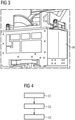
- 3 shows an embodiment of a 3D measuring device M according to the invention. 3 shows a full scanner. In this case, a 3D measuring head 3 according to figure 1 with a structure 1 according to 2 connected.
- a 3D measuring head is linearly movably connected to the structure such that in a second step S2 the 3D measuring head can be moved through the elongated recesses, for example the grooves, and measured.
- the resulting measurement data are assembled into a 3D model of the scanned groove using appropriate software.
- certain measured variables such as distances and wear, are determined in this 3D model.
- the computer required for this or the computer device required for this can be integrated into the overall structure in order to be independent of additional hardware.
- the computer device advantageously has a processor unit and a memory device for storing 3D models.
- figure 5 shows a representation of a further embodiment of a method according to the invention. It also takes place according to 4 the first two steps S1 and S2, a step S0 of positioning and fastening the structure to an elongated recess, in particular a groove, of a body, here a gas turbine rotor, having been carried out beforehand. Steps S0 and S1 can be carried out simultaneously if the structure 1 is positioned and fastened together with the 3D measuring head 3 in an embodiment of the 3D measuring device M according to the invention on the groove or on the body having grooves.
- figure 5 represents the second step S2 of three-dimensional scanning of the surface of the groove by linearly guiding the 3D measuring head along the longitudinal axis of the groove.
- FIG. 12 illustrates the further work steps, with processing and 3D reconstruction of the 3D data generated by the 3D measuring head being carried out using a computer device to form a 3D model of the groove being specified as step S3.
- FIG. 12 also shows that the computer device is used to analyze the 3D measurement data, in particular by comparing the 3D model with a CAD model of the groove in a step S4. An ideal groove course is shown in contrast to a course of a worn groove with an impaired surface.
- figure 5 shows the work steps S0 to S4 of a LASER-based complete 3D contour measurement of gas turbine rotor grooves for the analysis of a stress on elongated recesses, in particular grooves. Accuracies of up to around 20pm can be achieved.
- figure 5 shows a 3D measuring device M as a mobile and completely self-sufficient scanning unit having a 3D scanning head, an integrated computer device for automatic analysis and data storage.
- a final step After a first step S1 of aligning the 3D measuring device M within the groove using the tool platform, after a second step S2 of a linear movement of the 3D measuring head along the groove for data acquisition and after a third step S3 of data evaluation for calculation of measured variables, in particular lengths, in a final step the 3D measuring device M is detached from the measured groove and the procedure is repeated on the next groove to be measured.
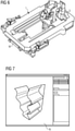
- FIG. 6 shows a further exemplary embodiment of a 3D measuring device M.
- This lightweight variant of the 3D measuring device M does not have an integrated computer device, with the structure 1 together with the 3D measuring head 3 being operated solely by means of purely mechanical components.
- the display 7 shows a display of a computer device.
- the display shows a computed 3D model representation of an actual elongate recess in the configuration of a groove N which has been scanned and measured for wear.
Landscapes
- Engineering & Computer Science (AREA)
- Physics & Mathematics (AREA)
- General Physics & Mathematics (AREA)
- Mechanical Engineering (AREA)
- General Engineering & Computer Science (AREA)
- Length Measuring Devices With Unspecified Measuring Means (AREA)
- Length Measuring Devices By Optical Means (AREA)
Description
- Die Erfindung betrifft eine 3D-Messvorrichtung und ein Verfahren zur dreidimensionalen Erfassung von länglichen Ausnehmungen, insbesondere Nuten, insbesondere Rotornuten.
- Bei Servicearbeiten ist eine optische Inspektion und 3D-Vermessung von länglichen Ausnehmungen, insbesondere Nuten, insbesondere von Gasturbinenrotornuten, erforderlich, wobei insbesondere gerade Nutenverläufe sichergestellt werden müssen. Nuten unterliegen im laufenden Betrieb einer Abnutzung und Verformung, was dazu führen kann, dass sich der Sitz von Turbinenschaufeln lockert und im Extremfall eine Turbine zerstört wird.
- Herkömmlicherweise wird ein Teilabdruck von länglichen Ausnehmungen, insbesondere Nuten mittels Zahnabdruckmasse genommen und im Anschluss mittels Profilprojektoren vermessen.
- Darüber hinaus ist aus der
WO 2015/014652 A1 ein Verfahren zur dreidimensionalen Erfassung eines länglichen Innenraumes mittels einer Lichtlinie bekannt. - Die
US 2015/0308813 A1 offenbart eine Vorrichtung zum berührungslosen Vermessen schwalbenschwanzartiger Ausbuchtungen eines Turbinenrads mittels einer Lasereinrichtung. - Ein Verfahren zum Vermessen von Querrillen einer Rohrverbindung ist aus der
WO 2012/069154 A1 bekannt. - Aus der
EP 1 416 122 A2 sind eine Vorrichtung und ein Verfahren zum Messen von Durchmessern länglicher Aussparungen eines Gasturbinenrotors durch Aufspannen zweier Stifte bekannt. - Es ist Aufgabe der Erfindung eine 3D-Messvorrichtung und ein Verfahren zur dreidimensionalen Erfassung von länglichen Ausnehmungen, insbesondere Nuten, insbesondere Rotornuten, derart bereit zu stellen, dass eine Inspektion und eine dreidimensionale (3D-) Vermessung von länglichen Ausnehmungen, insbesondere Nuten, insbesondere deren geraden Verläufe, einfach, wirksam, sicher, wiederholbar und zuverlässig ausführbar ist.
- Eine Ausnehmung ist insbesondere ein räumlicher Bereich eines Materialkörpers, in dem kein Material des Körpers vorhanden ist.
- Die Aufgabe wird durch eine 3D-Messvorrichtung gemäß dem Hauptanspruch 1 und ein 3D-Messverfahren gemäß dem Nebenanspruch 4 gelöst.
- Gemäß einem ersten Aspekt wird eine 3D-Messvorrichtung zur dreidimensionalen Erfassung von länglichen Ausnehmungen, insbesondere Nuten, insbesondere Rotornuten, vorgeschlagen, wobei ein Aufbau zur Positionierung und Befestigung an einer Nut eines Körpers, insbesondere eines Rotors und ein mit dem Aufbau verbundener und zur Nut ausrichtbarer 3D-Messkopf zur jeweiligen 3D-Oberflächenmessung der Nut verwendet werden.
- Der Aufbau umfasst eine Klemmeinrichtung mit Klemmbacken, welche jeweils mit einer Endoberfläche zweier Stirnseiten der länglichen Ausnehmung mechanisch kontaktierbar und lösbar befestigbar sind. Der Aufbau weist eine entlang einer zweiten Längsachse sich räumlich erstreckende und mit dieser parallel zu der ersten Längsachse ausrichtbare Aussparung aufweisende und die Längliche Ausnehmung einrahmende Platte auf, die mit einer Zentriereinrichtung und der Klemmeinrichtung fest verbunden ist, wobei die Zentriereinrichtung mindestens eine Zentrierbacke aufweist.
- Gemäß einem zweiten Aspekt wird ein Verfahren zur dreidimensionalen Erfassung von länglichen Ausnehmungen, insbesondere Nuten, insbesondere Rotornuten, nach Anspruch 4 vorgeschlagen. Die erfindungsgemäße 3D-Messvorrichtung zur Vermessung von länglichen Ausnehmungen, insbesondere Nuten beispielsweise von Gasturbinen beruht auf einer Kombination eines 3D-Scankopfes, der ebenso als 3D-Messkopf bezeichnet werden kann, mit einem Aufbau, der ebenso als Werkzeugplattform bezeichnet werden kann.
- Mittels der Erfindung kann vorteilhafterweise ein Messvorgang schnell und automatisiert ausgeführt werden, wobei eine Nut beispielsweise innerhalb einer Minute vermessen werden kann. Weiterhin kann eine Vermessung einer kompletten Nutoberfläche entlang der vollständigen Nutlänge ausgeführt werden. Eine hochgenaue Vermessung insbesondere in einem Bereich bis zu 20pm ist möglich. Ein Verschleiß und eine Verformung von länglichen Ausnehmungen, insbesondere Nuten kann digitalisiert und einfach dokumentiert werden.
- Weitere vorteilhafte Ausgestaltungen werden in Verbindung mit den Unteransprüchen beansprucht.
- Gemäß einer vorteilhaften Ausgestaltung kann eine Rechnereinrichtung zur Verarbeitung und 3D-Rekonstruktion der mittels des 3D-Messkopfes erzeugten 3D-Daten der Nut zu einem 3D-Modell der Nut bereitgestellt sein.
- Gemäß einer weiteren vorteilhaften Ausgestaltung kann die Rechnereinrichtung zur Analyse der 3D-Messdaten mittels Vergleichen des 3D-Modells mit einem Computer-Admitted-Design-Modell der Nut geschaffen sein.
- Gemäß einer weiteren vorteilhaften Ausgestaltung kann mittels einer Rechnereinrichtung ein Verarbeiten und 3D-Rekonstruieren der mittels des 3D-Messkopfes erzeugten 3D-Daten zu einem 3D-Modell der Nut ausgeführt werden.
- Gemäß einer weiteren vorteilhaften Ausgestaltung kann mittels der Rechnereinrichtung eine Analyse der 3D-Messdaten mittels Vergleichen des 3D-Modells mit einem CAD-Modell der Nut ausgeführt werden.
- Gemäß einer weiteren vorteilhaften Ausgestaltung kann mittels der Rechnereinrichtung ein Anzeigen von Modellen der Nut insbesondere an einem Bildschirm ausgeführt werden.
- Gemäß einer weiteren vorteilhaften Ausgestaltung kann ein Lösen des Aufbaus zusammen mit dem 3D-Messkopf von der Nut und ein Positionieren und Befestigen an einer weiteren Nut ausgeführt werden.
- Die Erfindung wird anhand von Ausführungsbeispielen in Verbindung mit den Figuren näher beschrieben. Es zeigen:
- Fig. 1
- eine mögliche Ausgestaltung des 3D-Messkopfes als die eines sogenannten mehrdirektionalen Ein-Chip-Triangulationssystems;
- Fig. 2
- eine Ausgestaltung einer Werkzeugplattform;
- Fig. 3
- ein Ausführungsbeispiel einer erfindungsgemäßen 3D-Messvorrichtung;
- Fig. 4
- ein Ausführungsbeispiel eines erfindungsgemäßen Verfahrens;
- Fig. 5
- eine Darstellung zu einem weiteren Ausführungsbeispiel eines erfindungsgemäßen Verfahrens;
- Fig. 6
- ein weiteres Ausführungsbeispiel einer 3D-Messvorrichtung;
- Fig. 7
- eine Anzeige einer Rechnereinrichtung.
-
Fig. 1 zeigt ein Ausführungsbeispiel eines 3D-Messkopfes 3. Dabei ist der 3D-Messkopf 3, der ebenso als 3D-Scankopf bezeichnet werden kann, mit einer Linearführung ausgestaltet.Fig. 1 zeigt den 3D-Messkopf 3 zur mittels Triangulation ausgeführten 3D-Messung eines, insbesondere eine Ausnehmung aufweisenden, Objektes, insbesondere einer Nut, einer Spalte oder einer Röhre, wobei zwischen einer einzigen Erfassungseinrichtung und dem Objekt eine eine Mehrzahl getrennter optische Wege erzeugende optischen Einrichtung positioniert ist, die ein einziges ohne optische Einrichtung ursprüngliches Sichtfeld der Erfassungseinrichtung in eine Mehrzahl von Untersichtfeldern aufteilt und die einzige Erfassungseinrichtung die Untersichtfelder getrennt erfasst. - Eine Ausnehmung ist insbesondere ein räumlicher Bereich eines Materialkörpers, in dem kein Material des Körpers vorhanden ist.
- Der 3D-Messkopf 3 kann ebenso als "Multi directional single chip triangulation system" also als "Mehrrichtungs-Einzelchip-Triangulationssystem" oder als "optischer 3D Messtaster" bezeichnet werden. Die Triangulation kann insbesondere eine aktive Triangulation sein, die beispielsweise Laserlinienverformungen zur Berechnung verwendet.
- Zur aktiven Triangulation kann mindestens eine Projektionseinrichtung ausgebildet sein, die in jedem Untersichtfeld ein Muster erzeugt, das auf das Objekt projizierbar ist.
- Zur passiven Triangulation kann für jedes Untersichtfeld in der einzigen Erfassungseinrichtung ein Stereo-System ausgebildet sein, mittels dem jeweils das Objekt erfassbar ist.
-
Fig. 2 zeigt ein Ausführungsbeispiel eines Aufbaus 1, der ebenso als Werkzeugplattform bezeichnet werden kann. Der Aufbau eignet sich vorteilhaft zur Aufnahme eines 3D-Messkopfes 3 gemäßFig. 1 . Gemäß einem Aspekt wird ein Aufbau zur Positionierung und Befestigung eines an den Aufbau befestigbaren Werkzeuges an einer sich entlang einer ersten Längsachse räumlich erstreckenden, insbesondere einen Öffnungswinkel und an zwei Stirnseiten vier Endoberflächen aufweisenden länglichen Ausnehmung, insbesondere Nut, insbesondere eines Rotors, vorgeschlagen, wobei der Aufbau eine entlang einer zweiten Längsachse sich räumlich erstreckende und mit dieser parallel zu der ersten Längsachse ausrichtbare, eine Aussparung aufweisende und die längliche Ausnehmung einrahmende Platte aufweist, die mit einer Zentriereinrichtung und einer Klemmeinrichtung fest verbunden ist, wobei die Zentriereinrichtung mindestens eine Zentrierbacke aufweist. Diese ist beispielsweise in einem Querschnitt zu der zweiten Längsachse ein einen Öffnungswinkel der länglichen Ausnehmung nachbildender Keil, der in der Aussparung entlang der zweiten Längsachse und beispielsweise lotrecht zur Platte in die sowie aus der länglichen Ausnehmung, insbesondere Nut, bewegbar ist, wobei die Klemmeinrichtung auf der der länglichen Ausnehmung zugewandten Seite der Platte Klemmbacken aufweist, die jeweils entlang der zweiten Längsachse bewegbar und mit einer der, insbesondere vier, Endoberflächen der zwei Stirnseiten der länglichen Ausnehmung, insbesondere Nut, mechanisch kontaktierbar und lösbar befestigbar sind. - Eine Aussparung ist insbesondere ein räumlicher Bereich eines Materialkörpers, in dem kein Material des Körpers vorhanden ist. Die Aussparung kann als durchgängige Öffnung erzeugt sein.
- Die mindestens eine Zentrierbacke kann sich in einem Querschnitt zu der zweiten Längsachse über den Verlauf der länglichen Ausnehmung in einem Querschnitt zu der ersten Längsachse räumlich hinaus erstrecken und in die längliche Ausnehmung klemmbar sein. Die Zentrierbacken können sich in Richtung zu der länglichen Ausnehmung im Querschnitt verjüngen.
- Es können beispielsweise zwei einen Öffnungswinkel der länglichen Ausnehmung entsprechende Keile erzeugende Zentrierbacken und vier Klemmbacken geschaffen sind.
- Es wird ein Bearbeitungsaufbau für längliche Ausnehmungen, insbesondere Nuten, insbesondere für Gasturbinen-Rotornuten, als eine mechanische Basis für die Anwendung verschiedener Werkzeuge vorgeschlagen. Dieser Bearbeitungsaufbau weist insbesondere eine Zentrierungs- und eine Klemmeinrichtung aus.
Fig. 3 zeigt ein Ausführungsbeispiel einer erfindungsgemäßen 3D-Messvorrichtung M.Fig. 3 zeigt einen vollständigen Scanner. Dabei ist ein 3D-Messkopf 3 gemäßFigur 1 mit einem Aufbau 1 gemäßFig. 2 verbunden. -
Fig. 4 zeigt ein Ausführungsbeispiel eines erfindungsgemäßen Verfahrens. Mit einem ersten Schritt S1 wird ein 3D-Messkopf linear beweglich mit dem Aufbau derart verbunden, dass in einem zweiten Schritt S2 der 3D-Messkopf durch die länglichen Ausnehmungen beispielsweise die Nuten bewegt und gemessen werden kann. Mit einem dritten Schritt S3 werden die entstehenden Messdaten mittels einer entsprechenden Software zu einem 3D-Modell der abgetasteten Nut zusammengesetzt. In einem Unterschritt werden in diesem 3D-Modell bestimmte Messgrößen, beispielsweise Abstände und Abnutzungen, ermittelt. Der hierfür notwendige Computer oder die hierfür notwendige Rechnereinrichtung kann in den Gesamtaufbau integriert werden, um unabhängig von zusätzlicher Hardware zu sein. Die Rechnereinrichtung weist vorteilhaft eine Prozessoreinheit und eine Speichereinrichtung zum Speichern von 3D-Modellen auf. -
Fig. 5 zeigt eine Darstellung zu einem weiteren Ausführungsbeispiel eines erfindungsgemäßen Verfahrens. Es erfolgen ebenso gemäßFig. 4 die ersten beiden Schritte S1 und S2, wobei vorher noch ein Schritt S0 eines Positionieren und Befestigen des Aufbaus an einer länglichen Ausnehmung insbesondere Nut eines Körpers, hier eines Gasturbinenrotors ausgeführt wurde. Schritte S0 und S1 können gleichzeitig ausgeführt werden, wenn der Aufbau 1 zusammen mit dem 3D-Messkopf 3 in Ausgestaltung der erfindungsgemäßen 3D-Messvorrichtung M an der Nut oder auf dem Nuten aufweisenden Körper positioniert und befestigt wird.Fig. 5 stellt den zweiten Schritt S2 des dreidimensionalen Abtastens der Oberfläche der Nut mittels linearen Führens des 3D-Messkopfes entlang der Längsachse der Nut dar.Fig. 5 veranschaulicht die weiteren Arbeitsschritte, wobei ein mittels einer Rechnereinrichtung ausgeführtes Verarbeiten und 3D-Rekonstruieren der mittels des 3D-Messkopfes erzeugten 3D-Daten zu einem 3D-Modell der Nut als Schritt S3 angegeben ist.Fig. 5 zeigt zudem, dass mittels der Rechnereinrichtung eine Analyse der 3D-Messdaten, insbesondere mittels Vergleichens des 3D-Modells mit einem CAD-Modell der Nut in einem Schritt S4 ausgeführt wird. Dabei ist ein Idealnutenverlauf im Unterschied zu einem Verlauf einer abgenutzten Nut mit einer beeinträchtigten Oberfläche dargestellt.Fig. 5 zeigt die Arbeitsschritte S0 bis S4 einer LASER basierten kompletten 3D-Konturmessung von Gasturbinenrotornuten zur Analyse einer Beanspruchung von länglichen Ausnehmungen, insbesondere Nuten. Es können Genauigkeiten bis circa 20pm bewirkt werden.Fig. 5 zeigt eine 3D-Messvorrichtung M als mobile und komplett autarke Scaneinheit aufweisend einen 3D-Scankopf, eine integrierte Rechnereinrichtung zur automatischen Analyse und Datenspeicherung. - Es kann nach einem ersten Schritt S1 eines Ausrichtens der 3D-Messvorrichtung M innerhalb der Nut mittels der Werkzeugplattform, nach einem zweiten Schritt S2 einer Linearbewegung des 3D-Messkopfes entlang der Nut zur Datenaufnahme und nach einem dritten Schritt S3 der Datenauswertung zur Berechnung von Messgrößen, insbesondere Längen, in einem abschließenden Schritt ein Lösen der 3D-Messvorrichtung M von der vermessenen Nut und ein Wiederholen des Vorgehens an der nächsten zu vermessenden Nut ausgeführt werden.
-
Fig. 6 zeigt ein weiteres Ausführungsbeispiel einer 3D-Messvorrichtung M. Diese leichte Variante der 3D-Messvorrichtung M weist keine integrierte Rechnereinrichtung auf, wobei zudem der Aufbau 1 zusammen mit dem 3D-Messkopf 3 lediglich mittels rein mechanischer Komponenten betrieben wird. -
Fig. 7 zeigt eine Anzeige einer Rechnereinrichtung. Die Anzeige zeigt die Darstellung eines berechneten 3D-Modells einer tatsächlichen länglichen Ausnehmung in Ausgestaltung einer Nut N, die nach einer Abnutzung abgetastet und gemessen wurde.
Claims (8)
- 3D-Messvorrichtung (M) zur dreidimensionalen Erfassung von länglichen Ausnehmungen,insbesondere Nuten,insbesondere Rotornuten,mit einem Aufbau (1) zur Positionierung und Befestigung an einer länglichen Ausnehmung eines Körpers,insbesondere eines Rotors und mit einem mit dem Aufbau verbundenen und zur länglichen Ausnehmung ausrichtbaren 3D-Messkopf (3) zur jeweiligen 3D-Oberflächenvermessung der länglichen Ausnehmung,gekennzeichnet durcheine Klemmeinrichtung des Aufbaus (1) mit Klemmbacken, welche jeweils mit einer Endoberfläche zweier Stirnseiten der länglichen Ausnehmung mechanisch kontaktierbar und lösbar befestigbar sind,wobei der Aufbau eine entlang einer zweiten Längsachse sich räumlich erstreckende und mit dieser parallel zu der ersten Längsachse ausrichtbare Aussparung aufweisende und die längliche Ausnehmung einrahmende Platte aufweist,die mit einer Zentriereinrichtung und der Klemmeinrichtung fest verbunden ist,wobei die Zentriereinrichtung mindestens eine Zentrierbacke aufweist.
- 3D-Messvorrichtung (M) gemäß Anspruch 1,
gekennzeichnet durch eine Rechnereinrichtung zur Verarbeitung und 3D-Rekonstruktion der mittels des 3D-Messkopfes erzeugten 3D-Daten der länglichen Ausnehmung zu einem 3D-Modell der länglichen Ausnehmung. - 3D-Messvorrichtung (M) gemäß Anspruch 2,
gekennzeichnet durch die Rechnereinrichtung zur Analyse der 3D-Messdaten mittels Vergleichen des 3D-Modells mit einem CAD-(Computer-Admitted- Design-) Modell der länglichen Ausnehmung. - Verfahren zur dreidimensionalen Erfassung von länglichen Ausnehmungen, insbesondere Nuten, insbesondere Rotornuten, gekennzeichnet durch(S0;S1) Positionieren und Befestigen eines Aufbaus nach Anspruch 1 an einer länglichen Ausnehmung eines Körpers, insbesondere eines Rotors, durch mechanisches Kontaktieren von Klemmbacken einer Klemmeinrichtung des Aufbaus (1) mit jeweiligen Endoberflächen zweier Stirnseiten der länglichen Ausnehmung, wobei mit dem Aufbau ein 3D-Messkopf verbunden und zu der länglichen Ausnehmung zur jeweiligen 3D-Oberflächenvermessung ausgerichtet ist;(S2) dreidimensionales Abtasten der Oberfläche der länglichen Ausnehmung mittels linearen Führens des 3D-Messkopfes entlang einer Längsachse der länglichen Ausnehmung.
- Verfahren gemäß Anspruch 4, gekennzeichnet durch mittels einer Rechnereinrichtung ausgeführtes Verarbeiten und 3D-Rekonstruieren (S3) der mittels des 3D-Messkopfes erzeugten 3D-Daten zu einem 3D-Modell der länglichen Ausnehmung.
- Verfahren gemäß Anspruch 5, gekennzeichnet durch mittels der Rechnereinrichtung ausgeführte Analyse (S4) der 3D-Messdaten mittels Vergleichen des 3D-Modells mit einem CAD-Modell der länglichen Ausnehmung.
- Verfahren gemäß Anspruch 6, gekennzeichnet durch mittels der Rechnereinrichtung ausgeführte Anzeigen von Modellen der länglichen Ausnehmung.
- Verfahren gemäß einem der vorhergehenden Ansprüche 1 bis 7, gekennzeichnet durch Lösen des Aufbaus (S5) zusammen mit dem 3D-Messkopf von der Nut und Positionieren und Befestigen an einer weiteren länglichen Ausnehmung.
Applications Claiming Priority (2)
| Application Number | Priority Date | Filing Date | Title |
|---|---|---|---|
| DE102016205217.9A DE102016205217A1 (de) | 2016-03-30 | 2016-03-30 | 3D-Messung von länglichen Ausnehmungen, insbesondere Nuten |
| PCT/EP2016/080093 WO2017167413A1 (de) | 2016-03-30 | 2016-12-07 | 3d-messung von länglichen ausnehmungen, insbesondere nuten |
Publications (2)
| Publication Number | Publication Date |
|---|---|
| EP3384231A1 EP3384231A1 (de) | 2018-10-10 |
| EP3384231B1 true EP3384231B1 (de) | 2022-02-02 |
Family
ID=57570052
Family Applications (1)
| Application Number | Title | Priority Date | Filing Date |
|---|---|---|---|
| EP16812706.6A Not-in-force EP3384231B1 (de) | 2016-03-30 | 2016-12-07 | 3d-messung von länglichen ausnehmungen, insbesondere nuten |
Country Status (4)
| Country | Link |
|---|---|
| US (1) | US11307022B2 (de) |
| EP (1) | EP3384231B1 (de) |
| DE (1) | DE102016205217A1 (de) |
| WO (1) | WO2017167413A1 (de) |
Families Citing this family (1)
| Publication number | Priority date | Publication date | Assignee | Title |
|---|---|---|---|---|
| DE102016205217A1 (de) | 2016-03-30 | 2017-10-05 | Siemens Aktiengesellschaft | 3D-Messung von länglichen Ausnehmungen, insbesondere Nuten |
Citations (1)
| Publication number | Priority date | Publication date | Assignee | Title |
|---|---|---|---|---|
| EP1568439A1 (de) * | 2004-02-25 | 2005-08-31 | Diag-Metal | Verfahren und Vorrichtung zur Wiederherstellung von Zähnen bei Zahnrädern |
Family Cites Families (13)
| Publication number | Priority date | Publication date | Assignee | Title |
|---|---|---|---|---|
| US4960285A (en) * | 1988-09-22 | 1990-10-02 | Katsumi Doi | Jaw assembly |
| US5019129A (en) * | 1990-07-18 | 1991-05-28 | Lars Johanson | Workpiece holding system |
| DK0497730T3 (da) * | 1991-01-28 | 1994-09-26 | Hydrostress Ag | Føringsskinne med støttebuk til væg- og gulvfræsemaskiner |
| JP2518687Y2 (ja) * | 1992-04-06 | 1996-11-27 | 株式会社イトーキクレビオ | 蟻溝付きフレーム装置 |
| US6745622B2 (en) * | 2002-10-31 | 2004-06-08 | General Electric Company | Apparatus and method for inspecting dovetail slot width for gas turbine engine disk |
| US8152419B1 (en) * | 2008-11-25 | 2012-04-10 | Holly R Snyder | Tubular member notching system and method |
| DE102009022957A1 (de) * | 2009-05-28 | 2010-12-02 | Wafios Ag | Kopfstauchvorrichtung |
| FR2968073B1 (fr) | 2010-11-26 | 2012-11-16 | Vallourec Mannesmann Oil & Gas | Procede et dispositif de controle d'un filetage de joint tubulaire utilise dans l'industrie du petrole |
| DE102013214997A1 (de) | 2013-07-31 | 2015-02-05 | Siemens Aktiengesellschaft | Anordnung zur dreidimensionalen Erfassung eines länglichen Innenraumes |
| DE102013108895B3 (de) * | 2013-08-16 | 2014-12-24 | Rattunde & Co Gmbh | Twinspanner und Verfahren zum gleichzeitigen Einspannen von zwei Langprofilabschnitten |
| DE102014103799B4 (de) * | 2014-03-20 | 2018-07-05 | Voss Fluid Gmbh | Umformwerkzeug für ein Werkstück und Vorrichtung zum Verformen eines Werkstücks mit einem derartigen Werkzeug |
| US9470508B2 (en) | 2014-04-23 | 2016-10-18 | General Electric Company | Non-contact coordinate measuring system |
| DE102016205217A1 (de) | 2016-03-30 | 2017-10-05 | Siemens Aktiengesellschaft | 3D-Messung von länglichen Ausnehmungen, insbesondere Nuten |
-
2016
- 2016-03-30 DE DE102016205217.9A patent/DE102016205217A1/de not_active Withdrawn
- 2016-12-07 US US16/089,257 patent/US11307022B2/en active Active
- 2016-12-07 EP EP16812706.6A patent/EP3384231B1/de not_active Not-in-force
- 2016-12-07 WO PCT/EP2016/080093 patent/WO2017167413A1/de not_active Ceased
Patent Citations (1)
| Publication number | Priority date | Publication date | Assignee | Title |
|---|---|---|---|---|
| EP1568439A1 (de) * | 2004-02-25 | 2005-08-31 | Diag-Metal | Verfahren und Vorrichtung zur Wiederherstellung von Zähnen bei Zahnrädern |
Also Published As
| Publication number | Publication date |
|---|---|
| DE102016205217A1 (de) | 2017-10-05 |
| US20190120614A1 (en) | 2019-04-25 |
| WO2017167413A1 (de) | 2017-10-05 |
| US11307022B2 (en) | 2022-04-19 |
| EP3384231A1 (de) | 2018-10-10 |
Similar Documents
| Publication | Publication Date | Title |
|---|---|---|
| EP1711777B1 (de) | Verfahren zur bestimmung der lage und der relativverschiebung eines objekts im raum | |
| WO2014114737A2 (de) | Verfahren und vorrichtung zur bestimmung der geometrie von strukturen mittels computertomografie | |
| EP3044536B1 (de) | Verfahren und vorrichtung zur vermessung von innengewinden eines werkstücks mit einem optischen sensor | |
| EP2663963B1 (de) | Vorrichtung und verfahren zum erfassen der lage eines objekts in einer werkzeugmaschine | |
| WO2016041695A1 (de) | Verfahren und vorrichtung zum identifizieren von strukturelementen eines projizierten strukturmusters in kamerabildern | |
| DE102008027393A1 (de) | Optische Überwachungseinrichtung | |
| DE102008019435B4 (de) | Verfahren zum berührungslosen Vermessen dreidimensionaler, komplex geformter Bauteile | |
| DE10322762B4 (de) | Halter für einen Rohling und Verfahren zur Vermessung der Lage und Orientierung des Halters | |
| DE102015108809B4 (de) | Verfahren zum Bearbeiten eines dentalen Rohlings | |
| DE102016205217A1 (de) | 3D-Messung von länglichen Ausnehmungen, insbesondere Nuten | |
| WO2019195870A1 (de) | Verfahren zur erstellung von 3d-bearbeitungsdaten einer kfz-felge | |
| DE60032635T2 (de) | Verfahren und vorrichtung zum testen von werkzeugmaschinen | |
| EP4607300A1 (de) | Werkzeug-einstell- und/oder werkzeug-messsystem, werkzeug- einstell- und/oder werkzeug-messverfahren, computerprogrammprodukt und steuer- und/oder regeleinheit | |
| WO2019015887A1 (de) | Verfahren zum betrieb einer bearbeitungsanlage mit beweglichem stempel | |
| DE19525987A1 (de) | Verfahren zum Vermessen einer sich etwa in einer Längsrichtung erstreckten Raumkontur | |
| DE102012018776A1 (de) | Prüfvorrichtung und Verfahren zur Prüfung einer Außenoberfläche eines bruchgetrennten Werkstücks | |
| DE10319711A1 (de) | Verfahren zur hochgenauen dimensionalen Messung an Messobjekten | |
| DE19736588A1 (de) | Optoelektronisches Entfernungs-Meßverfahren sowie Entfernungsmeßeinrichtung zur Verfahrensdurchführung | |
| EP3383581B1 (de) | Aufbau für längliche ausnehmungen, insbesondere nuten | |
| EP4305498B1 (de) | Verfahren zur erzeugung einer virtuellen geometrie und system dazu | |
| DE102006005990A1 (de) | Werkstückvermessung für 3-D Lageerkennung in mehreren Multi-Roboter-Stationen | |
| DE102020107643B4 (de) | Spannvorrichtung und Koordinatenmessgerät | |
| EP1407222A1 (de) | Verfahren zum scannenden messen einer oberflächenkontur | |
| EP3696496B1 (de) | Überprüfen von vermessungsparametereinstellungen für den betrieb eines koordinatenmessgeräts | |
| WO2025051452A1 (de) | Verfahren zum befunden eines bauteils |
Legal Events
| Date | Code | Title | Description |
|---|---|---|---|
| STAA | Information on the status of an ep patent application or granted ep patent |
Free format text: STATUS: UNKNOWN |
|
| STAA | Information on the status of an ep patent application or granted ep patent |
Free format text: STATUS: THE INTERNATIONAL PUBLICATION HAS BEEN MADE |
|
| PUAI | Public reference made under article 153(3) epc to a published international application that has entered the european phase |
Free format text: ORIGINAL CODE: 0009012 |
|
| STAA | Information on the status of an ep patent application or granted ep patent |
Free format text: STATUS: REQUEST FOR EXAMINATION WAS MADE |
|
| 17P | Request for examination filed |
Effective date: 20180703 |
|
| AK | Designated contracting states |
Kind code of ref document: A1 Designated state(s): AL AT BE BG CH CY CZ DE DK EE ES FI FR GB GR HR HU IE IS IT LI LT LU LV MC MK MT NL NO PL PT RO RS SE SI SK SM TR |
|
| AX | Request for extension of the european patent |
Extension state: BA ME |
|
| DAV | Request for validation of the european patent (deleted) | ||
| DAX | Request for extension of the european patent (deleted) | ||
| RAP1 | Party data changed (applicant data changed or rights of an application transferred) |
Owner name: SIEMENS ENERGY GLOBAL GMBH & CO. KG |
|
| STAA | Information on the status of an ep patent application or granted ep patent |
Free format text: STATUS: EXAMINATION IS IN PROGRESS |
|
| 17Q | First examination report despatched |
Effective date: 20210301 |
|
| REG | Reference to a national code |
Ref country code: DE Ref legal event code: R079 Ref document number: 502016014483 Country of ref document: DE Free format text: PREVIOUS MAIN CLASS: G01B0021040000 Ipc: F01D0025280000 |
|
| GRAP | Despatch of communication of intention to grant a patent |
Free format text: ORIGINAL CODE: EPIDOSNIGR1 |
|
| RIC1 | Information provided on ipc code assigned before grant |
Ipc: F01D 25/28 20060101AFI20210525BHEP Ipc: G01B 5/00 20060101ALI20210525BHEP Ipc: G01B 11/24 20060101ALI20210525BHEP Ipc: G01B 21/04 20060101ALI20210525BHEP |
|
| STAA | Information on the status of an ep patent application or granted ep patent |
Free format text: STATUS: GRANT OF PATENT IS INTENDED |
|
| INTG | Intention to grant announced |
Effective date: 20210701 |
|
| RIN1 | Information on inventor provided before grant (corrected) |
Inventor name: KOERDEL, MARTIN Inventor name: EULER, HELMUTH Inventor name: HEINE, WOLFGANG Inventor name: GERGEN, WERNER Inventor name: PHILIPPI, UWE Inventor name: SCHICK, ANTON |
|
| GRAS | Grant fee paid |
Free format text: ORIGINAL CODE: EPIDOSNIGR3 |
|
| GRAA | (expected) grant |
Free format text: ORIGINAL CODE: 0009210 |
|
| STAA | Information on the status of an ep patent application or granted ep patent |
Free format text: STATUS: THE PATENT HAS BEEN GRANTED |
|
| AK | Designated contracting states |
Kind code of ref document: B1 Designated state(s): AL AT BE BG CH CY CZ DE DK EE ES FI FR GB GR HR HU IE IS IT LI LT LU LV MC MK MT NL NO PL PT RO RS SE SI SK SM TR |
|
| REG | Reference to a national code |
Ref country code: GB Ref legal event code: FG4D Free format text: NOT ENGLISH |
|
| REG | Reference to a national code |
Ref country code: CH Ref legal event code: EP Ref country code: AT Ref legal event code: REF Ref document number: 1466642 Country of ref document: AT Kind code of ref document: T Effective date: 20220215 |
|
| REG | Reference to a national code |
Ref country code: DE Ref legal event code: R096 Ref document number: 502016014483 Country of ref document: DE |
|
| REG | Reference to a national code |
Ref country code: IE Ref legal event code: FG4D Free format text: LANGUAGE OF EP DOCUMENT: GERMAN |
|
| REG | Reference to a national code |
Ref country code: LT Ref legal event code: MG9D |
|
| REG | Reference to a national code |
Ref country code: NL Ref legal event code: MP Effective date: 20220202 |
|
| PG25 | Lapsed in a contracting state [announced via postgrant information from national office to epo] |
Ref country code: SE Free format text: LAPSE BECAUSE OF FAILURE TO SUBMIT A TRANSLATION OF THE DESCRIPTION OR TO PAY THE FEE WITHIN THE PRESCRIBED TIME-LIMIT Effective date: 20220202 Ref country code: RS Free format text: LAPSE BECAUSE OF FAILURE TO SUBMIT A TRANSLATION OF THE DESCRIPTION OR TO PAY THE FEE WITHIN THE PRESCRIBED TIME-LIMIT Effective date: 20220202 Ref country code: PT Free format text: LAPSE BECAUSE OF FAILURE TO SUBMIT A TRANSLATION OF THE DESCRIPTION OR TO PAY THE FEE WITHIN THE PRESCRIBED TIME-LIMIT Effective date: 20220602 Ref country code: NO Free format text: LAPSE BECAUSE OF FAILURE TO SUBMIT A TRANSLATION OF THE DESCRIPTION OR TO PAY THE FEE WITHIN THE PRESCRIBED TIME-LIMIT Effective date: 20220502 Ref country code: NL Free format text: LAPSE BECAUSE OF FAILURE TO SUBMIT A TRANSLATION OF THE DESCRIPTION OR TO PAY THE FEE WITHIN THE PRESCRIBED TIME-LIMIT Effective date: 20220202 Ref country code: LT Free format text: LAPSE BECAUSE OF FAILURE TO SUBMIT A TRANSLATION OF THE DESCRIPTION OR TO PAY THE FEE WITHIN THE PRESCRIBED TIME-LIMIT Effective date: 20220202 Ref country code: HR Free format text: LAPSE BECAUSE OF FAILURE TO SUBMIT A TRANSLATION OF THE DESCRIPTION OR TO PAY THE FEE WITHIN THE PRESCRIBED TIME-LIMIT Effective date: 20220202 Ref country code: ES Free format text: LAPSE BECAUSE OF FAILURE TO SUBMIT A TRANSLATION OF THE DESCRIPTION OR TO PAY THE FEE WITHIN THE PRESCRIBED TIME-LIMIT Effective date: 20220202 Ref country code: BG Free format text: LAPSE BECAUSE OF FAILURE TO SUBMIT A TRANSLATION OF THE DESCRIPTION OR TO PAY THE FEE WITHIN THE PRESCRIBED TIME-LIMIT Effective date: 20220502 |
|
| PG25 | Lapsed in a contracting state [announced via postgrant information from national office to epo] |
Ref country code: PL Free format text: LAPSE BECAUSE OF FAILURE TO SUBMIT A TRANSLATION OF THE DESCRIPTION OR TO PAY THE FEE WITHIN THE PRESCRIBED TIME-LIMIT Effective date: 20220202 Ref country code: LV Free format text: LAPSE BECAUSE OF FAILURE TO SUBMIT A TRANSLATION OF THE DESCRIPTION OR TO PAY THE FEE WITHIN THE PRESCRIBED TIME-LIMIT Effective date: 20220202 Ref country code: GR Free format text: LAPSE BECAUSE OF FAILURE TO SUBMIT A TRANSLATION OF THE DESCRIPTION OR TO PAY THE FEE WITHIN THE PRESCRIBED TIME-LIMIT Effective date: 20220503 Ref country code: FI Free format text: LAPSE BECAUSE OF FAILURE TO SUBMIT A TRANSLATION OF THE DESCRIPTION OR TO PAY THE FEE WITHIN THE PRESCRIBED TIME-LIMIT Effective date: 20220202 |
|
| PG25 | Lapsed in a contracting state [announced via postgrant information from national office to epo] |
Ref country code: IS Free format text: LAPSE BECAUSE OF FAILURE TO SUBMIT A TRANSLATION OF THE DESCRIPTION OR TO PAY THE FEE WITHIN THE PRESCRIBED TIME-LIMIT Effective date: 20220602 |
|
| PG25 | Lapsed in a contracting state [announced via postgrant information from national office to epo] |
Ref country code: SM Free format text: LAPSE BECAUSE OF FAILURE TO SUBMIT A TRANSLATION OF THE DESCRIPTION OR TO PAY THE FEE WITHIN THE PRESCRIBED TIME-LIMIT Effective date: 20220202 Ref country code: SK Free format text: LAPSE BECAUSE OF FAILURE TO SUBMIT A TRANSLATION OF THE DESCRIPTION OR TO PAY THE FEE WITHIN THE PRESCRIBED TIME-LIMIT Effective date: 20220202 Ref country code: RO Free format text: LAPSE BECAUSE OF FAILURE TO SUBMIT A TRANSLATION OF THE DESCRIPTION OR TO PAY THE FEE WITHIN THE PRESCRIBED TIME-LIMIT Effective date: 20220202 Ref country code: EE Free format text: LAPSE BECAUSE OF FAILURE TO SUBMIT A TRANSLATION OF THE DESCRIPTION OR TO PAY THE FEE WITHIN THE PRESCRIBED TIME-LIMIT Effective date: 20220202 Ref country code: DK Free format text: LAPSE BECAUSE OF FAILURE TO SUBMIT A TRANSLATION OF THE DESCRIPTION OR TO PAY THE FEE WITHIN THE PRESCRIBED TIME-LIMIT Effective date: 20220202 Ref country code: CZ Free format text: LAPSE BECAUSE OF FAILURE TO SUBMIT A TRANSLATION OF THE DESCRIPTION OR TO PAY THE FEE WITHIN THE PRESCRIBED TIME-LIMIT Effective date: 20220202 |
|
| REG | Reference to a national code |
Ref country code: DE Ref legal event code: R097 Ref document number: 502016014483 Country of ref document: DE |
|
| PG25 | Lapsed in a contracting state [announced via postgrant information from national office to epo] |
Ref country code: AL Free format text: LAPSE BECAUSE OF FAILURE TO SUBMIT A TRANSLATION OF THE DESCRIPTION OR TO PAY THE FEE WITHIN THE PRESCRIBED TIME-LIMIT Effective date: 20220202 |
|
| PLBE | No opposition filed within time limit |
Free format text: ORIGINAL CODE: 0009261 |
|
| STAA | Information on the status of an ep patent application or granted ep patent |
Free format text: STATUS: NO OPPOSITION FILED WITHIN TIME LIMIT |
|
| 26N | No opposition filed |
Effective date: 20221103 |
|
| PGFP | Annual fee paid to national office [announced via postgrant information from national office to epo] |
Ref country code: FR Payment date: 20221214 Year of fee payment: 7 Ref country code: DE Payment date: 20220617 Year of fee payment: 7 |
|
| PG25 | Lapsed in a contracting state [announced via postgrant information from national office to epo] |
Ref country code: SI Free format text: LAPSE BECAUSE OF FAILURE TO SUBMIT A TRANSLATION OF THE DESCRIPTION OR TO PAY THE FEE WITHIN THE PRESCRIBED TIME-LIMIT Effective date: 20220202 |
|
| PGFP | Annual fee paid to national office [announced via postgrant information from national office to epo] |
Ref country code: IT Payment date: 20221227 Year of fee payment: 7 Ref country code: GB Payment date: 20230119 Year of fee payment: 7 |
|
| REG | Reference to a national code |
Ref country code: CH Ref legal event code: PL |
|
| REG | Reference to a national code |
Ref country code: BE Ref legal event code: MM Effective date: 20221231 |
|
| PG25 | Lapsed in a contracting state [announced via postgrant information from national office to epo] |
Ref country code: LU Free format text: LAPSE BECAUSE OF NON-PAYMENT OF DUE FEES Effective date: 20221207 |
|
| PG25 | Lapsed in a contracting state [announced via postgrant information from national office to epo] |
Ref country code: LI Free format text: LAPSE BECAUSE OF NON-PAYMENT OF DUE FEES Effective date: 20221231 Ref country code: IE Free format text: LAPSE BECAUSE OF NON-PAYMENT OF DUE FEES Effective date: 20221207 Ref country code: CH Free format text: LAPSE BECAUSE OF NON-PAYMENT OF DUE FEES Effective date: 20221231 |
|
| PG25 | Lapsed in a contracting state [announced via postgrant information from national office to epo] |
Ref country code: BE Free format text: LAPSE BECAUSE OF NON-PAYMENT OF DUE FEES Effective date: 20221231 |
|
| REG | Reference to a national code |
Ref country code: AT Ref legal event code: MM01 Ref document number: 1466642 Country of ref document: AT Kind code of ref document: T Effective date: 20221207 |
|
| PG25 | Lapsed in a contracting state [announced via postgrant information from national office to epo] |
Ref country code: HU Free format text: LAPSE BECAUSE OF FAILURE TO SUBMIT A TRANSLATION OF THE DESCRIPTION OR TO PAY THE FEE WITHIN THE PRESCRIBED TIME-LIMIT; INVALID AB INITIO Effective date: 20161207 |
|
| PG25 | Lapsed in a contracting state [announced via postgrant information from national office to epo] |
Ref country code: AT Free format text: LAPSE BECAUSE OF NON-PAYMENT OF DUE FEES Effective date: 20221207 |
|
| PG25 | Lapsed in a contracting state [announced via postgrant information from national office to epo] |
Ref country code: CY Free format text: LAPSE BECAUSE OF FAILURE TO SUBMIT A TRANSLATION OF THE DESCRIPTION OR TO PAY THE FEE WITHIN THE PRESCRIBED TIME-LIMIT Effective date: 20220202 Ref country code: AT Free format text: LAPSE BECAUSE OF NON-PAYMENT OF DUE FEES Effective date: 20221207 |
|
| PG25 | Lapsed in a contracting state [announced via postgrant information from national office to epo] |
Ref country code: MK Free format text: LAPSE BECAUSE OF FAILURE TO SUBMIT A TRANSLATION OF THE DESCRIPTION OR TO PAY THE FEE WITHIN THE PRESCRIBED TIME-LIMIT Effective date: 20220202 |
|
| PG25 | Lapsed in a contracting state [announced via postgrant information from national office to epo] |
Ref country code: MC Free format text: LAPSE BECAUSE OF FAILURE TO SUBMIT A TRANSLATION OF THE DESCRIPTION OR TO PAY THE FEE WITHIN THE PRESCRIBED TIME-LIMIT Effective date: 20220202 |
|
| PG25 | Lapsed in a contracting state [announced via postgrant information from national office to epo] |
Ref country code: MC Free format text: LAPSE BECAUSE OF FAILURE TO SUBMIT A TRANSLATION OF THE DESCRIPTION OR TO PAY THE FEE WITHIN THE PRESCRIBED TIME-LIMIT Effective date: 20220202 |
|
| REG | Reference to a national code |
Ref country code: DE Ref legal event code: R119 Ref document number: 502016014483 Country of ref document: DE |
|
| GBPC | Gb: european patent ceased through non-payment of renewal fee |
Effective date: 20231207 |
|
| PG25 | Lapsed in a contracting state [announced via postgrant information from national office to epo] |
Ref country code: MT Free format text: LAPSE BECAUSE OF FAILURE TO SUBMIT A TRANSLATION OF THE DESCRIPTION OR TO PAY THE FEE WITHIN THE PRESCRIBED TIME-LIMIT Effective date: 20220202 |
|
| PG25 | Lapsed in a contracting state [announced via postgrant information from national office to epo] |
Ref country code: DE Free format text: LAPSE BECAUSE OF NON-PAYMENT OF DUE FEES Effective date: 20240702 |
|
| PG25 | Lapsed in a contracting state [announced via postgrant information from national office to epo] |
Ref country code: GB Free format text: LAPSE BECAUSE OF NON-PAYMENT OF DUE FEES Effective date: 20231207 |
|
| PG25 | Lapsed in a contracting state [announced via postgrant information from national office to epo] |
Ref country code: FR Free format text: LAPSE BECAUSE OF NON-PAYMENT OF DUE FEES Effective date: 20231231 |
|
| PG25 | Lapsed in a contracting state [announced via postgrant information from national office to epo] |
Ref country code: GB Free format text: LAPSE BECAUSE OF NON-PAYMENT OF DUE FEES Effective date: 20231207 Ref country code: FR Free format text: LAPSE BECAUSE OF NON-PAYMENT OF DUE FEES Effective date: 20231231 Ref country code: DE Free format text: LAPSE BECAUSE OF NON-PAYMENT OF DUE FEES Effective date: 20240702 |
|
| PG25 | Lapsed in a contracting state [announced via postgrant information from national office to epo] |
Ref country code: IT Free format text: LAPSE BECAUSE OF NON-PAYMENT OF DUE FEES Effective date: 20231207 |
|
| PG25 | Lapsed in a contracting state [announced via postgrant information from national office to epo] |
Ref country code: TR Free format text: LAPSE BECAUSE OF FAILURE TO SUBMIT A TRANSLATION OF THE DESCRIPTION OR TO PAY THE FEE WITHIN THE PRESCRIBED TIME-LIMIT Effective date: 20220202 |