EP3383793B1 - Techniques for quantum error correction using bosonic modes and related systems and methods - Google Patents
Techniques for quantum error correction using bosonic modes and related systems and methods Download PDFInfo
- Publication number
- EP3383793B1 EP3383793B1 EP16892925.5A EP16892925A EP3383793B1 EP 3383793 B1 EP3383793 B1 EP 3383793B1 EP 16892925 A EP16892925 A EP 16892925A EP 3383793 B1 EP3383793 B1 EP 3383793B1
- Authority
- EP
- European Patent Office
- Prior art keywords
- state
- error
- qubit
- parity
- cavity resonator
- Prior art date
- Legal status (The legal status is an assumption and is not a legal conclusion. Google has not performed a legal analysis and makes no representation as to the accuracy of the status listed.)
- Active
Links
Images


Classifications
-
- G—PHYSICS
- G06—COMPUTING OR CALCULATING; COUNTING
- G06N—COMPUTING ARRANGEMENTS BASED ON SPECIFIC COMPUTATIONAL MODELS
- G06N10/00—Quantum computing, i.e. information processing based on quantum-mechanical phenomena
- G06N10/70—Quantum error correction, detection or prevention, e.g. surface codes or magic state distillation
-
- G—PHYSICS
- G06—COMPUTING OR CALCULATING; COUNTING
- G06F—ELECTRIC DIGITAL DATA PROCESSING
- G06F11/00—Error detection; Error correction; Monitoring
- G06F11/07—Responding to the occurrence of a fault, e.g. fault tolerance
- G06F11/08—Error detection or correction by redundancy in data representation, e.g. by using checking codes
- G06F11/10—Adding special bits or symbols to the coded information, e.g. parity check, casting out 9's or 11's
-
- G—PHYSICS
- G06—COMPUTING OR CALCULATING; COUNTING
- G06F—ELECTRIC DIGITAL DATA PROCESSING
- G06F11/00—Error detection; Error correction; Monitoring
- G06F11/30—Monitoring
- G06F11/32—Monitoring with visual or acoustical indication of the functioning of the machine
- G06F11/321—Display for diagnostics, e.g. diagnostic result display, self-test user interface
- G06F11/322—Display of waveforms, e.g. of logic analysers
-
- G—PHYSICS
- G06—COMPUTING OR CALCULATING; COUNTING
- G06N—COMPUTING ARRANGEMENTS BASED ON SPECIFIC COMPUTATIONAL MODELS
- G06N10/00—Quantum computing, i.e. information processing based on quantum-mechanical phenomena
- G06N10/40—Physical realisations or architectures of quantum processors or components for manipulating qubits, e.g. qubit coupling or qubit control
-
- B—PERFORMING OPERATIONS; TRANSPORTING
- B82—NANOTECHNOLOGY
- B82Y—SPECIFIC USES OR APPLICATIONS OF NANOSTRUCTURES; MEASUREMENT OR ANALYSIS OF NANOSTRUCTURES; MANUFACTURE OR TREATMENT OF NANOSTRUCTURES
- B82Y10/00—Nanotechnology for information processing, storage or transmission, e.g. quantum computing or single electron logic
Definitions
- Quantum information processing techniques perform computations by manipulating one or more quantum objects. These techniques are sometimes referred to as "quantum computing.” In order to perform computations, a quantum information processor utilizes quantum objects to reliably store and retrieve information. According to some quantum information processing approaches, a quantum analogue to the classical computing "bit" (being equal to 1 or 0) has been developed, which is referred to as a quantum bit, or "qubit.”
- a qubit can be composed of any quantum system that has two distinct states (which may be thought of as 1 and 0 states), but also has the special property that the system can be placed into quantum superpositions and thereby exist in both of those states at once.
- qubit can be composed of any quantum system that has two distinct states (which may be thought of as 1 and 0 states), but also has the special property that the system can be placed into quantum superpositions and thereby exist in both of those states at once.
- the present application relates to an improved quantum error correction technique for correcting errors in the state of a quantum system exhibiting one or more bosonic modes.
- An "error" in this context refers to a change in the state of the quantum system that may be caused by, for instance, boson losses, boson gains, dephasing, time evolution of the system, etc., and which alters the state of the system such that the information stored in the system is altered.
- quantum multi-level systems such as qubits exhibit quantum states that, based on current experimental practices, decohere in around ⁇ 100 ⁇ s. While experimental techniques will undoubtedly improve on this and produce qubits with longer decoherence times, it may nonetheless be beneficial to couple a multi-level system to another system that exhibits much longer decoherence times.
- bosonic modes are particularly desirable for coupling to a multi-level system. Through this coupling, the multi-level system's state may be represented by the bosonic mode(s) instead, thereby maintaining the same information yet in a longer-lived state than would otherwise exist in the multi-level system alone.
- Quantum information stored in bosonic modes may nonetheless still have a limited lifetime, such that errors will still occur within the bosonic system. It may therefore be desirable to manipulate a bosonic system when errors in its state occur to effectively correct those errors and thereby regain the prior state of the system. If a broad class of errors can be corrected for, it may be possible to maintain the state of the bosonic system indefinitely (or at least for long periods of time) by correcting for any type of error that might occur.
- the fields of cavity quantum electrodynamics (cavity QED) and circuit QED represent one illustrative experimental approach to implement quantum error correction.
- one or more qubit systems are each coupled to a resonator cavity in such a way as to allow mapping of the quantum information contained in the qubit(s) to and/or from the resonator(s).
- the resonator(s) generally will have a longer stable lifetime than the qubit(s).
- the quantum state may later be retrieved in a qubit by mapping the state back from a respective resonator to the qubit.
- a code might represent the ground state of a qubit using the zero boson number state of a resonator and represent the excited state of a qubit using the one boson number state of the resonator. That is: ⁇
- g ⁇ is the ground state of the qubit
- e ⁇ is the excited state of the qubit
- ⁇ and ⁇ are complex numbers representing the probability amplitude of the qubit being in state
- error words When an error occurs, the system's state transforms to a superposition of resulting states, herein termed "error words,"
- examples of errors include boson loss, boson gain, dephasing, amplitude dampening, etc.
- the choice of code affects how robust the system is to errors. That is, the code used determines to what extent a prior state can be faithfully recovered when an error occurs. A desirable code would be associated with a broad class of errors for which no information is lost when any of the errors occurs and any quantum superposition of the logical codewords can be faithfully recovered. Some codes, while robust against certain errors, may however be impractical to realize in a physical system.
- the inventors have recognized and appreciated a class of codes that protect against a wide array of errors that can occur in a bosonic system, including boson gain, boson loss, dephasing, and amplitude dampening, and that can be realized experimentally. Codes from this class are referred to herein as "binomial codes," since the class of codes may be described by a binomial distribution, as described below.
- the inventors have developed techniques for correcting errors when a code from this class is utilized to store a state in a bosonic system. In particular, the inventors have developed unitary operations that may be applied to the bosonic system based upon a detected error. Furthermore, the inventors have recognized and appreciated experimental configurations in which energy may be applied to a bosonic system, such as a cavity resonator, to perform the above-mentioned unitary operations.
- a binomial code may be used to configure a state of a single mode bosonic system.
- Bosonic systems may be particularly desirable systems in which to apply the techniques described herein, as a single bosonic mode may exhibit equidistant spacing of coherent states.
- a resonator cavity for example, is a simple harmonic oscillator with equidistant level spacing.
- Bosonic modes are also helpful for quantum communications in that they can be stationary for quantum memories or for interacting with conventional qubits, or they can be propagating ("flying") for quantum communication (e.g., they can be captured and released from resonators).
- a single bosonic mode in particular may allow for states having lower mean bosonic numbers than states produced by multiple bosonic modes.
- boson loss rate tends to scale with mean boson number
- a single bosonic mode will generally have a lower error rate than multiple bosonic modes.
- error correction of a single bosonic mode does not require mode-to-mode entangling operations that would otherwise be needed for multiple bosonic modes.
- the binomial codes described herein utilize bosonic number states of a single bosonic mode to represent the codewords, as described below.
- a bosonic system may be used in conjunction with a binomial code to act as a quantum memory device.
- a multi-level system such as a qubit, may store one or more quantum bits in a state that will decoherence in a short time scale, as described above. This state may instead be stored in a bosonic system encoded via the selected binomial code. This system will also decoherence, although typically in a longer time scale than that exhibited by the multi-level system.
- the binomial code may allow for correction of errors that occur to a perfect, or near perfect, degree such that the state of the bosonic system can be maintained. In this manner, the bosonic system acts as a quantum memory with respect to the quantum bit(s) originally stored in the multi-level system. If desired, the state in the bosonic system can be later transferred back to the multi-level system.
- a detector may be configured to monitor the bosonic system to detect when an error occurs. It is a feature of the binomial codes described herein that such a detector may be able to detect whether any error occurred, and also detect which type of error occurred, whilst preserving the state of the bosonic system. This type of measurement is sometimes referred to as a quantum nondemolition measurement (QND). Not all codes exhibit this feature, as for some codes a detection of an error may yield information on which of the two codewords is a more likely state of the system (recall that a given code stores a state in a quantum superposition of the two selected codewords). This carrying away of information as result of the measurement causes a change in the state of the quantum system.
- QND quantum nondemolition measurement
- the binomial codes described herein provide for detection of a broad class of errors, where in each case detection does not change the boson number of the state of the system.
- detection does not change the boson number of the state of the system.
- the backaction of this operation causes amplitude damping of the bosonic mode. Amplitude damping does not change the boson number of the bosonic system, but does change the probabilities of measuring each of the different boson numbers.
- the binomial codes described herein provide an explicit construction for repumping energy into the bosonic system to recover from amplitude damping, however. Accordingly, whether an error is detected or not, techniques described herein in conjunction with a binomial code allow maintenance of the bosonic system's state via application of a unitary operation to counteract the amplitude dampening effect.
- One of the binomial codes uses the following codewords (that is, a bosonic system is encoded in a superposition of the two codeword states as shown in FIGs. 1A-1B ):
- W ⁇ ⁇ 1 2
- W ⁇ ⁇
- the mean boson number n 2 for each state. Accordingly, the loss or gain of a boson (for example) does not produce information on which of the two codeword states the photon came from. This preserves the number state of the bosonic system upon detection of the boson loss or gain.
- bosonic system were a photonic system
- one way to detect the photon loss would be to detect the photon exiting the system using a photodetector. In many experimental configurations, however, this may be difficult or impractical to perform.
- another way to detect boson loss is to examine the parity (odd or even boson number state). Before the error, both codeword states would produce even parity, since all of the boson number states of those codewords are even parity states. After the boson loss, the parity would be odd, irrespective of the particular superposition of error word states, since both have odd parity.
- the system can be driven to the previous state by applying a unitary operation that performs the following transformation:
- a system configured to have universal control over the quantum state of a system can be operated to perform this type of state transformation.
- One reason the binomial codes allow for this type of correction is that the error words (e.g., 13) and 11) in the above example) for a binomial code are orthogonal. Therefore, a conditional unitary operation can be applied to transform the error word states into the corresponding codeword states irrespective of which of the error word states the system was in.
- FIG. 2 depicts an illustrative system suitable for practicing aspects of the present application.
- qubit 210 is coupled to a resonator 220 via coupling 215.
- the resonator may lose or gain energy (e.g., lose or gain bosons), may dephase, etc. and in the process may gain or lose energy as shown in the figure.
- Energy source 230 may supply energy to one or both of qubit 210 and resonator 220 in order to perform operations on the system such an encoding the state of the qubit in the resonator, encoding the state of the resonator in the qubit, applying unitary operations to the resonator (e.g., to correct an error detected in the resonator), applying unitary operations to the qubit, or combinations thereof.
- system 200 is provided as one illustrative system in which a qubit is coupled to a resonator.
- a mode of the resonator provides the bosonic mode in this example.
- System 200 also includes detector 240 which may be operated to detect the occurance of an error in the resonator 220.
- detector 240 may be operated to detect the occurance of an error in the resonator 220.
- a number of suitable approaches may be employed to operate such a detector, which may measure energy gain and/or loss from the resonator, may interact with the qubit 210 (e.g., may apply one or more unitary operations to the qubit and/or may measure the state of the qubit), and/or may interact with the resonator 220 (e.g., may apply one or more unitary operations to the resonator and/or may measure the state of the resonator). Any combination of such operations may obtain sufficient information about the qubit-resonator system to determine whether an error has occurred in the resonator 220.
- detector 240 applies one or more unitary operations to the qubit 210 and/or the resonator 220 by application of energy from energy source 230.
- the detector 240 comprises a photodetector or other particle detector configured to detect particles entering and/or exiting the resonator 220.
- detector 240 may perform a sequence of operations to measure one or more of parity mod 2, parity mod 3, parity mod N, etc. of the state of the resonator. As discussed below, such measurements may indicate whether boson losses or gains have occurred.
- Illustrative techniques for performing parity measurements in a qubit-resonator system are described, for example, in International Application No. PCT/US2016/043514, titled “Techniques of Oscillator State Manipulation for Quantum Information Processing and Related Systems and Methods," filed on July 22, 2016 , which is incorporated herein by reference in its entirety.
- Qubit 210 may include any suitable quantum system having two distinct states, such as but not limited to, those based on a superconducting Josephson junction such as a charge qubit (Cooper-pair box), flux qubit or phase qubit, or combinations thereof.
- the qubit 210 may be coupled to the resonator 220 via coupling 215 which couples the state of the qubit to the state of the resonator.
- the resonator 220 may include any resonator supporting one or more bosonic modes, which may be implemented using any electromagnetic, mechanical, magnetic (e.g., quantized spin waves also known as magnons), and/or other techniques, such as but not limited to any cavity resonator (e.g., a microwave cavity).
- resonator 220 may be a transmission line resonator.
- qubit 210 may be a charge qubit coupled to a superconducting transmission line cavity (an example of resonator 220) comprising a central conductor and ground planes on either side of the conductor separated by a length selected based upon the wavelength of photons trapped in the cavity.
- the length of the resonator may be a multiple of one half of such a wavelength.
- a length of the transmission line may also be selected based upon a desired impendence of the transmission line.
- a transmission line may have a length between 1 ⁇ m and 100 ⁇ m, such as between 5 ⁇ m and 50 ⁇ m, such as 10 ⁇ m.
- a transmission line may have a length between 5 mm and 50 mm, such as between 10 mm and 30 mm, such as 25 mm.
- the qubit may interact with the electric fields in the transmission line such that an adjustment to the state of the qubit causes an adjustment in the state of the resonator.
- Coupling 215 may utilize any technique(s) to couple the qubit and the resonator, such as by coupling the electric and/or magnetic fields generated by the qubit and the resonator.
- the qubit and the resonator may be dispersively coupled via the coupling 215.
- the qubit e.g., a transmon
- the qubit may be coupled to the resonator, being a mechanical resonator, via a piezoelectric coupling.
- the qubit may be coupled to the resonator, being a magnetic resonator, by coupling the qubit (e.g., a transmon) to phonons, which in turn couple to magnons via magnetostrictive coupling.
- resonator 220 may be used as a memory to store the state of qubit 210.
- the state of the resonator may be error-corrected using the techniques described herein. Subsequently, the state may be mapped to qubit 210 and/or any other qubit.
- the resonator 220 may be used as a transmission medium to transport the state of qubit 210 to another qubit, along a transmission line, and/or to another resonator.
- the state of the resonator during transmission may be error-corrected using the techniques described below. Subsequently, the state may be mapped to a target of the transmission.
- a state may be represented in the resonator 220 using one of the binomial codes.
- the energy source 230 may apply energy to the qubit and/or the resonator to correct errors based on the selected binomial code, as described in further detail below.
- quantum error correction comprises selecting logical codewords with which to represent a state, such as the state of a qubit.
- codewords are states embedded in a large Hilbert space, such as the space of a harmonic oscillator, such that no information is lost if any one of the single, independent error ⁇ k ⁇ ⁇ occurs and any quantum superposition of the logical codewords
- W ⁇ ⁇ , where ⁇ ⁇ , ⁇ , can be faithfully recovered.
- a binomial code may be used to encode the state of the resonator 220 based on the state of the qubit 210.
- Techniques for universal control may be applied to produce a superposition of the codeword states in the resonator based on the superposition of the ground and excited states present in the qubit, as shown in FIGs. 1A-1B .
- techniques described in the above-referenced International Application No. PCT/US2016/043514 describe techniques suitable for encoding the state of the qubit into the state of the resonator in system 200.
- such techniques may comprise operating energy source 230 to apply energy in a sequence of steps, wherein each step comprises application of energy to the qubit 210, to the resonator 220, or simultaneously to both the qubit and resonator.
- the encoding of a qubit state into a resonator state may be achieved as follows. Beginning with the state shown in FIG. 1A , with the resonator in the ground state (zero bosons), drive pulses are simultaneously applied to the qubit 210 and the resonator 220, which excite the bosonic mode while ultimately returning the qubit to the ground state. If the qubit 210 is initially in the ground state
- the drive pulses excite the bosonic mode to state
- the final state of the bosonic mode 220 is conditioned on the initial state of the qubit 210.
- the binomial codes may protect against up to L boson loss events occurring in the time interval dt between two consecutive quantum correction stages.
- a code that "protects" against a particular error means that the code is such that, when the error occurs, the previous state is recoverable via one or more unitary operations.
- a boson loss error brings the logical codewords
- the boson loss errors can be detected by measuring boson number mod 3.
- the error recovery procedure is similar as above: an error detection is followed by a unitary operation performing a state transfer
- Appendix A a family of codes can be developed that protect against any arbitrary number of boson loss errors L.
- the original state can then be recovered by making a unitary operation performing a state transfer
- W ⁇ ' ⁇ ( n + 1) ⁇ ⁇ ' .
- ⁇ ' 1 ⁇ 1, â , n ⁇ ⁇ achieved by the same Fock state coefficients as with the code (Eqn. 7) but with spacing of the code (Eqn. 6):
- W ⁇ ⁇
- 4 ⁇ 2 , W ⁇ 3
- a bosonic system that has a state encoding a two-level system may use any pair of codewords given by Eqn. 10 (i.e., for any combination of values of L, G and D) to describe the two level system; that is, the bosonic system may have a state ⁇
- binomial codes operate in a restricted Hilbert space, which could be beneficial for the practical construction of the unitary operators required for error diagnosis and recovery. This may particularly apply to errors involving â ⁇ operators, whose operation on conventional codes may be less straightforward than â operators alone.
- Eqn. 11 represents a class of codes with which to represent a two-level system (e.g., a qubit).
- the codes selected from the above-described class of binomial codes may be used to represent the state of qubit 210 in the resonator 220. Once an error occurs in the resonator, the error may be detected and operations may be performed to correct the error. The error-correction process is described in detail below with respect to FIG. 3 .
- FIG. 3 is a flowchart of a method of correcting errors that occur within a bosonic system, according to some embodiments.
- FIG. 3 may be performed within system 200 shown in FIG. 2 , for example.
- Method 300 includes steps of measuring an error syndrome of a bosonic system and performing a correction based on the measured error syndrome.
- Method 300 also includes an optional initial step in which the bosonic mode's state is encoded based on a coupled multi-level system.
- Method 300 can optionally begin in act 302 in which the state of a multi-level system is encoded in the state of a bosonic mode.
- this encoding may utilize any code selected from the above-described binomial codes to represent the state of the qubit in the bosonic mode.
- method 300 may begin in act 304 wherein a bosonic mode has been previously configured with a state that is a superposition of a pair of codewords selected from the class of binomial codes. Accordingly, irrespective of whether method 300 includes the optional encoding act 302, prior to act 304 the bosonic mode is in a state that is a superposition of a pair of codewords selected from the class of binomial codes or class of multinomial codes. For example, if the bosonic mode of method 300 represents a two-level system, it has a state that is a superposition of one of the pairs of codewords given by Eqn. 11.
- an error syndrome of the bosonic mode is measured.
- An "error syndrome” as used herein refers to a measurement that is indicative that a particular error (or one of a group of particular errors) has occurred.
- An error syndrome discussed above is a measurement that shows there has been a change in parity of the bosonic number state of the bosonic mode (or parity mod 3, parity mod 4, etc.).
- Another error syndrome is a measurement that indicates dephasing has occurred (an example of this type of measurement is discussed above).
- Another error syndrome is a measurement that indicates no error has occurred. Since the act of measuring the bosonic mode can cause amplitude damping of the mode, a measurement indicating no error has occurred may nonetheless lead to action based on this measurement, and therefore "no error" is also considered an error syndrome.
- detecting a boson loss or gain error in act 304 may comprise a sequence of operations in which energy is applied to the bosonic mode directly and/or to another system to which the bosonic mode is coupled.
- a resonator e.g., microwave cavity
- the qubit can be driven conditioned on given boson number states of the resonator.
- the electromagnetic pulse applied to the qubit can be selected such that, for example, the qubit will be in a particular state after application of the pulse that depends upon the boson number state of the resonator. Measurement of the qubit then indicates the parity of the coupled resonator.
- a measurement of boson number mod ( S +1) comprises performing S sequential measurements of the two-level qubit.
- , for d 0, 1, ..., N.
- E ⁇ ⁇ d ⁇ are linear combinations of ⁇ n l
- W ⁇ ⁇ l 0,1,..., N that satisfy the orthonormal condition: ⁇ E ⁇ ⁇ d
- the detection of a dephasing error may comprise a sequence of operations in which energy is applied to the bosonic mode directly and/or to another system to which the bosonic mode is coupled.
- electromagnetic pulses applied to the resonator and qubit can be selected such that, after application of the pulse(s), the qubit will be in a particular state that depends on the resonator being in the subspace spanned by
- Measurement of the qubit would then indicate whether the oscillator is in the subspace spanned by
- one or more electromagnetic pulses (which may be, for example, pre-computed) can be applied to the system to carry out unitary state transfer from
- act 304 comprises detection of "no error,” also referred to herein as a “no-jump error.”
- no error also referred to herein as a "no-jump error.”
- This backaction reduces the relative probability of the higher Fock states with respect to the lower ones, formally expressed with the factor exp(- ⁇ d tn ⁇ /2) in the error operators (see Eqn. 14 below). Correction of this error syndrome is discussed below.
- one or more operations are performed upon the bosonic mode to transform its state based on the error syndrome detected in act 304.
- This transformation is configured to counteract the error implied by the measured error syndrome - that is, to attempt to transition the system back to the state it was in prior to the error. In some, but not all, cases, this transformation can be exact. In other cases, the transformation may approximately return the system to its previous state.
- act 306 may apply the one or more operations based on an analysis of a bosonic mode that evolves over time.
- the transformation applied in act 306 is configured to transition the bosonic mode from a state that is a superposition of error word states back to the superposition of codeword states that the mode previously exhibited (e.g., produce the state transitions given by Eqn. 4).
- this transformation may be performed by application of a correction unitary ⁇ k to the bosonic mode to perform a state transfer between the logical codewords and the error words.
- R ⁇ k ⁇ kk ⁇ ⁇
- B ⁇ k U ⁇ k P k
- P ⁇ k ⁇ ⁇ B ⁇ k
- the correction unitary U ⁇ k ⁇ ⁇
- correction unitary ⁇ k may be applied to the resonator by an energy source supplying energy (e.g., a time-varying electromagnetic pulse) to the resonator and/or to a qubit to which the resonator is coupled (e.g., as described below in relation to FIG. 5 ).
- energy e.g., a time-varying electromagnetic pulse
- a plurality of operations may be performed to apply correction unitary ⁇ k to the resonator.
- Such operations may comprise one or more steps in which energy (e.g., a time-varying pulse) is applied to the qubit, to the resonator, or to the qubit and the resonator simultaneously.
- the transformation applied in act 306 is configured to recover the state prior to dephasing by performing a state transfer between the subspaces of the error and logical codewords (e.g., produce the state transitions given by Eqn. 4).
- the operator n ⁇ takes the state to a superposition of the logical codewords and an orthogonal set of errors words, as in Eqn. 8. This event can be diagnosed and the quantum state restored by a projective measurement followed by a conditional unitary operation.
- the transformation applied in act 306 is configured to recover a state prior to when the measurement was made.
- ⁇ ⁇ ⁇
- W ⁇ ⁇ transforms to
- ⁇ ′ ⁇ E ⁇ 0
- ⁇ ⁇ / ⁇ ⁇ E ⁇ 0 ⁇ E ⁇ 0 ⁇ ⁇ 1 2 under the no-jump evolution given by ⁇ 0 exp( - ⁇ d tn ⁇ /2) .
- the no-jump evolution can be determined to the same accuracy:
- ⁇ ⁇ + O ⁇ d t 2 ⁇
- W ⁇ ⁇ + O ⁇ d t 2
- E ⁇ 0 ⁇
- 4 ⁇ / 2 is the error word associated with the no-jump evolution.
- the recovery may be performed by a measurement projecting to the subspace of logical codewords.
- W ⁇ ⁇ , then also the observation of no-jump errors ⁇ L times yields no information and has measurement backaction that does not deform the state. In other words, the codes for ⁇ L ⁇ 1, â , â 2 , ... , â L ⁇ are protected against the no-jump evolution to the same order than the codes are protected against boson jump errors.
- FIG. 4 is a flowchart of a method of correcting one of three classes of errors that occur within a bosonic system, according to some embodiments.
- Method 400 is a particular example of method 300 performed within a system comprising a qubit coupled to an oscillator (e.g., system 500 discussed below in relation to FIG. 5 ).
- act 402 the state of the qubit is encoded in the oscillator using one of the binomial codes to represent the state of the qubit in the oscillator, illustrative techniques for which are discussed above.
- an error syndrome is detected that may be a photon gain/loss, dephasing, or a no-jump error, respectively. Illustrative techniques to detect such errors are discussed above.
- acts 405, 407 or 409, respectively transformations are applied to the qubit-oscillator system to correct these errors.
- acts 405, 407 and/or 409 may comprise application of electromagnetic pulses to the qubit and/or to the oscillator to perform unitary operations that perform such corrections. For example, those unitary operations discussed above in relation to FIG. 3 may be performed via said application of pulses.
- FIG. 5 is a block diagram of a circuit quantum electrodynamics system, according to some embodiments.
- System 500 includes a system 501 in addition to electromagnetic radiation source 530, controller 540 and storage medium 550.
- a library of precomputed drive waveforms may be stored on a computer readable storage medium and accessed in order to apply said waveforms to a quantum system.
- controller 540 accesses drive waveforms 552 stored on storage medium 550 (e.g., in response to user input provided to the controller) and controls the electromagnetic radiation source 530 to apply drive waveforms ⁇ q ( t ) and ⁇ osc ( t ) to the qubit and oscillator, respectively.
- System 501 includes a physical qubit 510 and a quantum mechanical oscillator 520.
- the qubit and the oscillator are dispersively coupled - that is, the qubit-oscillator detuning is much larger (e.g., an order of magnitude larger) than the coupling strength between the qubit and the oscillator.
- An electromagnetic signal ⁇ q ( t ) may be applied to the physical qubit 510 and an electromagnetic signal ⁇ osc ( t ) may be applied to the quantum mechanical oscillator 520.
- application of such an electromagnetic signal or pulse may also be referred to as "driving" of the qubit and/or oscillator.
- drive waveforms ⁇ q ( t ) and ⁇ osc ( t ) may be determined via numerical techniques for a particular desired state change of the system 500.
- suitable drive waveforms may be determined that allow ⁇ q ( t ) and ⁇ osc ( t ) to be applied simultaneously to the physical qubit and the oscillator, respectively.
- the drive waveforms ⁇ q ( t ) and ⁇ osc ( t ) may be applied during the same time period (i.e., may start and end together) or may simply overlap in time.
- the drive waveforms may be stored in the storage medium 550 in library 552, having been previously computed to transition the system 501 from an initial state to a desired final state.
- the drive waveforms may include waveforms that, when applied to the qubit 510 and oscillator 520, transition the oscillator from state that is a superposition of error words into a superposition of logical codeword states, as described above.
- the drive waveforms may include waveforms that, when applied to the qubit and the oscillator, produce the state transitions given by Eqn. 4.
- FIG. 6 illustrates a two-parameter ( N , S ) labeling of the binomial codes (Eqn. 11).
- the error words of a binomial code are also valid logical codewords but with a reduced value for the parameter N , since a boson loss or gain error decreases N ⁇ N -1 and a dephasing error reduces N ⁇ N - 2.
- FIG. 7 illustrates the rate of entanglement infidelity for binomial quantum error correction codes, according to some embodiments.
- the performance of a binomial code may be estimated by the rate of uncorrectable errors.
- the exact expression for the dominant uncorrectable error depends on the relative ratio of these rates.
- the boson loss channel is the dominating one, ⁇ > ⁇ + , ⁇ .
- a perfectly faithful recovery process is assumed for the purposes of illustration. Note the logarithmic scale of each axis.
- the entanglement infidelity is in general dependent on the input state. However, here we use the fully mixed state ⁇ c as an input since then the entanglement fidelity is equal to the ⁇ II component of the process map. At small d t , the slopes of F ⁇ e /d t agree well with the slopes for the rate of the largest uncorrectable error P L +1 /d t .
- an experimental infidelity ⁇ related to a single recovery stage increases the error rates by ⁇ /d t favoring low-order binomial codes with longer time steps (see Appendix C).
- the optimality of a code depends also on the detailed structure of the experimental recovery process; some of the infidelities can be correctable errors suppressed by the next round of the recovery process.
- the confidence of the error detection and consequently the fidelity of the recovery process can be improved by the means of quantum state filtering and smoothing, that is, using effectively the measurement record.
- bosonic mode quantum error correction is also useful for quantum communication which consists of quantum state transfer and generation of high-fidelity entangled pairs of quantum bits between two distant locations or nodes in a quantum network.
- a photonic or other bosonic system may be used as a communication medium wherein a quibit (or other quantum system) has its state mapped onto the bosonic system, which transmits or otherwise transfers the state across physical space, and maps the state onto a second qubit system. In this manner, the bosonic system acts akin to a fiber optic or other communication medium utilizing light by transporting information across a physical space.
- FIG. 8A is a sketch of a circuit QED hardware proposal
- FIG. 8B is a schematic of a quantum state transfer scenario utilizing encoding and quantum error correction of the binomial quantum states.
- FIGs. 8A-8B after encoding the qubit state to the send cavity, by controlling the cavity decay one can tailor a temporal mode for the flying, traveling oscillator mode that is fully absorbed by the receiving cavity.
- the received cavity state may have suffered from photon loss errors (Eqn. 14), dephasing and photon gain errors that can be recovered by performing the recovery process before decoding it to the physical qubit.
- the illustrative scenario of FIGs. 8A-8B comprises initializing the qubit A into a superposition of the ground and excited state ⁇
- the transfer is finalized by decoding (a unitary swap operation) the received cavity state to the qubit B resulting in ⁇
- the remote physical qubits can be entangled by replacing the first swap with a CNOT-gate between the physical qubit A and logical qubit of the cavity.
- the process is vulnerable to various errors and infidelities at the different stages of the transfer process.
- the most obvious imperfection is the attenuation of the state of the flying oscillator by photon loss processes, similar to (Eqns. 12-14), during the transmission.
- the local decoding and encoding operations between the cavity and qubit states can be imperfect as well.
- An important part of the 'pitch-and-catch' process is the engineering of the temporal mode of the flying oscillator so that the catch by the receiving cavity is as reflectionless as possible. Reflection can be modeled as an additional photon loss process.
- the cavities can suffer dephasing events through uncontrolled transitions of the qubits and the cavity states can decay also to unwanted channels not just to the transmission channel.
- phase-shift keying is a digital modulation scheme that conveys data by changing/modulating the phase of a reference signal.
- the quadrature phase-shift keying uses the 4 equal-spaced points ( ⁇ , i ⁇ , - ⁇ , -i ⁇ ) on a circle with radius ⁇ in the phase space to encode 2 classical bits of information.
- PSK can reliably encode the information so long as the phase of the reference signal can be reliably extracted. Owing to its simplicity, PSK is widely used in existing technologies in classical communication, such as the Bluetooth 2 standard and wireless LAN standard.
- the binomial codes can be regarded as a code that can correct multiple excitation loss errors, which can be used for quantum communication. In particular, it can be used for correcting photon loss errors in the third generation of quantum repeaters.
- QKD quantum key distribution
- the binomial codes defeat eavesdroppers. While an eavesdropper could try to probe the communicated codewords by removing a small number of photons from the code words or by acting with another operator that the code is protected against, the eavesdropper would not acquire any information about the word being sent. This is because those photon losses do not give any hint as to which code word they came from. Indeed, this is precisely why the intended receiver can still recover code words despite losses.
- the example of FIGs. 8A-8B could be repeated a number of times to cross a larger distance.
- a quantum repeater could be produced that utilized a number of cavities between an initial send cavity and a final receive cavity that each receive, then send the state (by leaking the state out of the cavity).
- a quantum communication system may be formed that links microwave resonators via optical fiber(s) and/or via other suitable means for propagating electromagnetic signals.
- optomechanical transducers can perform quantum state transfer from a microwave resonator to flying optical photons (and the reverse down-conversion) via an optomechanical transducer.
- Such converters could play a central role in quantum communications.
- such communication comprises up-conversion from microwave to optical, transmission of the optical state through a fiber and then down-conversion from optical to microwave at the remote location. All three steps could involve photon loss, gain or dephasing errors.
- W ⁇ ⁇ which can be corrected for such errors as described herein.
- FIG. 9 is a block diagram of a single-qubit, two-cavity system suitable for implementing two-mode codes.
- System 900 is another example of a system in which the two-mode (binomial) codes described above may be implemented.
- the single-qubit, two-cavity experimental configuration shown in FIG. 9 is in principle sufficient to realize universal control of the two modes for the following reasons.
- These identities can be applied and combined multiple times to produce superpositions of higher order commutators; [ ⁇ [ ⁇ , B ⁇ ]].
- each mode can be universally controlled, and that it is possible to generate a beamsplitter interaction x ⁇ i p ⁇ j - x ⁇ j p ⁇ i (equivivalent to a ⁇ i a ⁇ j ⁇ + a ⁇ j a ⁇ i ⁇ ) between different modes i ⁇ j.
- x ⁇ i p ⁇ j - x ⁇ j p ⁇ i Equivivalent to a ⁇ i a ⁇ j ⁇ + a ⁇ j a i ⁇
- Equation (A1) we show that the difference of the moments of W ⁇ and W ⁇ , ⁇ l ⁇ ⁇ W ⁇ n ⁇ l W ⁇ ⁇ ⁇ ⁇ W ⁇ n ⁇ l W ⁇ , ⁇ is zero.
- W ⁇ ⁇ ⁇ ⁇ 0 d are orthogonal.
- Equation (A7) yields d N +1 , proving that
- W ⁇ ⁇ ⁇ ⁇ 0 d are properly normalized.
- x w v .
- Equation (A12) contains at least one nonzero power of 1 + x + ... + x d -1 .
- the coefficient ⁇ 1 is the mean photon number of the codewords, which we see scales linearly with the spacing S , the qudit dimension d , and the maximum number of correctable errors of one type N .
- the binomial codes are tailored such that the photon loss and gain errors are detected by measuring changes in the generalized photon number parity that serves as a proxy to number of lost photons in a short time step.
- the strength of the dispersive coupling ⁇ is stronger than the decay rates of the qubit and the cavity, one can drive the qubit conditioned on given photon number states of the oscillator.
- the measurement of the qubit state realizes measurement of the generalized photon parity and projection of the cavity state by P ⁇ k mod L +1 .
- Error detection is followed by a correction unitary ⁇ k that performs a state transfer between the logical codewords
- B ⁇ k ⁇ B ⁇ k
- W ⁇ ⁇ , where the error operation B ⁇ k is the approximate of the Kraus operator ⁇ k to the L/2:th power in ⁇ Dt for k ⁇ 0 and for k 0 it is to the L:th power.
- a simple way of making a sub-leading improvement in the fidelity of the recovery process of the codes is to add a unitary 'echo' operation ⁇ x that performs state transfer
- W ⁇ ⁇ to the recovery operations R ⁇ ' l ⁇ x R ⁇ l .
- the most optimal recovery process of a binomial code can be found by overall minimizing the averaged infidelity that can require numerical optimization by semi-definite programming.
- the optimized recovery process cannot beat the overall accuracy limit set by the binomial code itself but the pre-factors of the higher-order, uncorrectable terms in the infidelity can be made considerably smaller.
- An analytic example is the code
- W ⁇ ⁇ 1 6 7 ⁇ 17
- W ⁇ ⁇ 1 6 9 ⁇ 17
- the error correction process starts by making a measurement that asks in which of the disjoint diagonalized error subspaces
- , where P ⁇ m are projectors to the m :th diagonalized error subspace: P ⁇ m ⁇ ⁇ m ⁇ 1
- the error correction is finalized by recovering the original state by a unitary operation ⁇ M that performs state transfer
- the normalized error words for the no-jump errors are
- E ⁇ 0 ⁇ 1 6 17 ⁇ 1
- E ⁇ 0 ⁇ 1 6 17 ⁇ 3
- E ⁇ 1 ⁇ 2 ,
- E ⁇ 1 ⁇
- E ⁇ 1 ⁇
- E ⁇ i 1 ⁇ is the error word after a photon loss from mode i .
- a parity measurement on each mode can distinguish from which mode the photon was lost, and so be used to determined whether to correct the error words
- the unitary operations required for error correction are swaps
- W ⁇ ⁇ , that is unitary operations U ⁇ i 1 ⁇ ⁇
- 1 r es denotes the identity operation that completes ⁇ i 1 to a unitary operation in the Hilbert space with total number of bosonic excitations ⁇ 4.
- the fidelity of the error correction may be determined by the rate of uncorrectable errors and for small ⁇ ⁇ t this is dominated by two photon losses.
- Which code is preferable will depend on the fidelity of the no-jump correction for the one-mode code, as the need for this operation may be eliminated in the two-mode case.
Landscapes
- Engineering & Computer Science (AREA)
- Theoretical Computer Science (AREA)
- Physics & Mathematics (AREA)
- General Physics & Mathematics (AREA)
- General Engineering & Computer Science (AREA)
- Evolutionary Computation (AREA)
- Software Systems (AREA)
- Condensed Matter Physics & Semiconductors (AREA)
- Mathematical Analysis (AREA)
- Mathematical Optimization (AREA)
- Pure & Applied Mathematics (AREA)
- Computing Systems (AREA)
- Computational Mathematics (AREA)
- Mathematical Physics (AREA)
- Data Mining & Analysis (AREA)
- Artificial Intelligence (AREA)
- Quality & Reliability (AREA)
- Human Computer Interaction (AREA)
- Superconductor Devices And Manufacturing Methods Thereof (AREA)
- Error Detection And Correction (AREA)
- Optical Modulation, Optical Deflection, Nonlinear Optics, Optical Demodulation, Optical Logic Elements (AREA)
- Optical Communication System (AREA)
- Digital Transmission Methods That Use Modulated Carrier Waves (AREA)
- Detection And Correction Of Errors (AREA)
- Testing Of Individual Semiconductor Devices (AREA)
Description
- Quantum information processing techniques perform computations by manipulating one or more quantum objects. These techniques are sometimes referred to as "quantum computing." In order to perform computations, a quantum information processor utilizes quantum objects to reliably store and retrieve information. According to some quantum information processing approaches, a quantum analogue to the classical computing "bit" (being equal to 1 or 0) has been developed, which is referred to as a quantum bit, or "qubit." A qubit can be composed of any quantum system that has two distinct states (which may be thought of as 1 and 0 states), but also has the special property that the system can be placed into quantum superpositions and thereby exist in both of those states at once. Several different types of qubits have been successfully demonstrated in the laboratory. However, the lifetime of the states of many of these systems before information is lost due to decoherence of the quantum state, or to other quantum noise, is currently around ~100µs. Notwithstanding longer lifetimes, it may be important to provide error correction techniques in quantum computing that enable reliable storage and retrieval of information stored in a quantum system. However, unlike a classical computing system in which bits can be copied for purposes of error correction, it may not be possible to clone an unknown state of a quantum system. The system may, however, be entangled with other quantum systems which effectively spreads the information in the system out over several entangled objects. Article entitled "Hardware-Efficient Autonomous Quantum Memory Protection" from Zaki Leghtas, Gerhard Kirchmair, Brian Vlastakis, Robert J. Schoelkopf, Michel H. Devoret, and Mazyar Mirrahimi (Phys. Rev. Lett. 111, 120501 - Published 20 September 2013) disclose examples of quantum information processing techniques
- The invention is defined by the appended claims. Embodiments of the invention are defined in the dependent claims.
- Various aspects and embodiments will be described with reference to the following figures. It should be appreciated that the figures are not necessarily drawn to scale. In the drawings, each identical or nearly identical component that is illustrated in various figures is represented by a like numeral. For purposes of clarity, not every component may be labeled in every drawing.
-
FIGs. 1A-1B illustrate encoding of the state of a multi-level quantum system in a bosonic system, according to some embodiments; -
FIG. 2 depicts an illustrative system suitable for practicing aspects of the present application; -
FIG. 3 is a flowchart of a method of correcting errors that occur within a bosonic system, according to some embodiments; -
FIG. 4 is a flowchart of a method of correcting one of three classes of errors that occur within a bosonic system, according to some embodiments; -
FIG. 5 is a block diagram of a circuit quantum electrodynamics system, according to some embodiments; -
FIG. 6 illustrates a two-parameter (N, S) space of binomial quantum error correction codes, according to some embodiments; -
FIG. 7 illustrates the rate of entanglement infidelity for binomial quantum error correction codes, according to some embodiments; -
FIG. 8A is a sketch of an illustrative circuit QED system; -
FIG. 8B is a schematic of a quantum state transfer scenario for the system depicted inFIG. 8A , utilizing encoding and quantum error correction of the binomial quantum states; and -
FIG. 9 is a block diagram of a single-qubit, two-cavity system suitable for implementing two-mode codes. - The present application relates to an improved quantum error correction technique for correcting errors in the state of a quantum system exhibiting one or more bosonic modes. An "error" in this context refers to a change in the state of the quantum system that may be caused by, for instance, boson losses, boson gains, dephasing, time evolution of the system, etc., and which alters the state of the system such that the information stored in the system is altered.
- As discussed above, quantum multi-level systems such as qubits exhibit quantum states that, based on current experimental practices, decohere in around ~100µs. While experimental techniques will undoubtedly improve on this and produce qubits with longer decoherence times, it may nonetheless be beneficial to couple a multi-level system to another system that exhibits much longer decoherence times. As will be described below, bosonic modes are particularly desirable for coupling to a multi-level system. Through this coupling, the multi-level system's state may be represented by the bosonic mode(s) instead, thereby maintaining the same information yet in a longer-lived state than would otherwise exist in the multi-level system alone.
- Quantum information stored in bosonic modes may nonetheless still have a limited lifetime, such that errors will still occur within the bosonic system. It may therefore be desirable to manipulate a bosonic system when errors in its state occur to effectively correct those errors and thereby regain the prior state of the system. If a broad class of errors can be corrected for, it may be possible to maintain the state of the bosonic system indefinitely (or at least for long periods of time) by correcting for any type of error that might occur.
- The fields of cavity quantum electrodynamics (cavity QED) and circuit QED represent one illustrative experimental approach to implement quantum error correction. In these approaches, one or more qubit systems are each coupled to a resonator cavity in such a way as to allow mapping of the quantum information contained in the qubit(s) to and/or from the resonator(s). The resonator(s) generally will have a longer stable lifetime than the qubit(s). The quantum state may later be retrieved in a qubit by mapping the state back from a respective resonator to the qubit.
- When a multi-level system, such as a qubit, is mapped onto the state of a bosonic system to which it is coupled, a particular way to encode the qubit state in the bosonic system must be selected. This choice of encoding is often referred to simply as a "code."
- As an example, a code might represent the ground state of a qubit using the zero boson number state of a resonator and represent the excited state of a qubit using the one boson number state of the resonator. That is:

- The use of a code can be written more generally as:

FIGs. 1A-1B graphically depict this process of encoding for some choice of |W↓〉 and |W↑〉. - When an error occurs, the system's state transforms to a superposition of resulting states, herein termed "error words,"


- In general, the choice of code affects how robust the system is to errors. That is, the code used determines to what extent a prior state can be faithfully recovered when an error occurs. A desirable code would be associated with a broad class of errors for which no information is lost when any of the errors occurs and any quantum superposition of the logical codewords can be faithfully recovered. Some codes, while robust against certain errors, may however be impractical to realize in a physical system.
- The inventors have recognized and appreciated a class of codes that protect against a wide array of errors that can occur in a bosonic system, including boson gain, boson loss, dephasing, and amplitude dampening, and that can be realized experimentally. Codes from this class are referred to herein as "binomial codes," since the class of codes may be described by a binomial distribution, as described below. The inventors have developed techniques for correcting errors when a code from this class is utilized to store a state in a bosonic system. In particular, the inventors have developed unitary operations that may be applied to the bosonic system based upon a detected error. Furthermore, the inventors have recognized and appreciated experimental configurations in which energy may be applied to a bosonic system, such as a cavity resonator, to perform the above-mentioned unitary operations.
- According to some embodiments, a binomial code may be used to configure a state of a single mode bosonic system. Bosonic systems may be particularly desirable systems in which to apply the techniques described herein, as a single bosonic mode may exhibit equidistant spacing of coherent states. A resonator cavity, for example, is a simple harmonic oscillator with equidistant level spacing. Bosonic modes are also helpful for quantum communications in that they can be stationary for quantum memories or for interacting with conventional qubits, or they can be propagating ("flying") for quantum communication (e.g., they can be captured and released from resonators). A single bosonic mode in particular may allow for states having lower mean bosonic numbers than states produced by multiple bosonic modes. Since boson loss rate tends to scale with mean boson number, a single bosonic mode will generally have a lower error rate than multiple bosonic modes. Moreover, error correction of a single bosonic mode does not require mode-to-mode entangling operations that would otherwise be needed for multiple bosonic modes. The binomial codes described herein utilize bosonic number states of a single bosonic mode to represent the codewords, as described below.
- According to some embodiments, a bosonic system may be used in conjunction with a binomial code to act as a quantum memory device. A multi-level system, such as a qubit, may store one or more quantum bits in a state that will decoherence in a short time scale, as described above. This state may instead be stored in a bosonic system encoded via the selected binomial code. This system will also decoherence, although typically in a longer time scale than that exhibited by the multi-level system. The binomial code may allow for correction of errors that occur to a perfect, or near perfect, degree such that the state of the bosonic system can be maintained. In this manner, the bosonic system acts as a quantum memory with respect to the quantum bit(s) originally stored in the multi-level system. If desired, the state in the bosonic system can be later transferred back to the multi-level system.
- According to some embodiments, a detector may be configured to monitor the bosonic system to detect when an error occurs. It is a feature of the binomial codes described herein that such a detector may be able to detect whether any error occurred, and also detect which type of error occurred, whilst preserving the state of the bosonic system. This type of measurement is sometimes referred to as a quantum nondemolition measurement (QND). Not all codes exhibit this feature, as for some codes a detection of an error may yield information on which of the two codewords is a more likely state of the system (recall that a given code stores a state in a quantum superposition of the two selected codewords). This carrying away of information as result of the measurement causes a change in the state of the quantum system.
- In contrast, the binomial codes described herein provide for detection of a broad class of errors, where in each case detection does not change the boson number of the state of the system. When a measurement of the bosonic system does not detect an error, however, the backaction of this operation causes amplitude damping of the bosonic mode. Amplitude damping does not change the boson number of the bosonic system, but does change the probabilities of measuring each of the different boson numbers. The binomial codes described herein provide an explicit construction for repumping energy into the bosonic system to recover from amplitude damping, however. Accordingly, whether an error is detected or not, techniques described herein in conjunction with a binomial code allow maintenance of the bosonic system's state via application of a unitary operation to counteract the amplitude dampening effect.
- An illustrative example of correcting errors using one of the binomial codes may be instructive. One of the binomial codes uses the following codewords (that is, a bosonic system is encoded in a superposition of the two codeword states as shown in
FIGs. 1A-1B ):
- Note that, for this pair of codewords, the mean boson number
n = 2 for each state. Accordingly, the loss or gain of a boson (for example) does not produce information on which of the two codeword states the photon came from. This preserves the number state of the bosonic system upon detection of the boson loss or gain. - If this bosonic system were to lose a boson (e.g., due to energy loss), it would be transformed as follows:


- One way to think about this transformation is that, if the system were in the |W↓〉 state, which is a superposition of 10) and 14), clearly a lost boson must have come from the 14) state and not the ground state. As such, the resulting state would be the 13) state. Similarly, if the system were in the |W↑〉 state, which is the 12) state, the resulting state after boson loss would be the 11) state.
- If the bosonic system were a photonic system, one way to detect the photon loss would be to detect the photon exiting the system using a photodetector. In many experimental configurations, however, this may be difficult or impractical to perform. As such, another way to detect boson loss is to examine the parity (odd or even boson number state). Before the error, both codeword states would produce even parity, since all of the boson number states of those codewords are even parity states. After the boson loss, the parity would be odd, irrespective of the particular superposition of error word states, since both have odd parity. This is an example of a measurement that, as described above, does not alter the bosonic number state of the system, since the information that is carried away is that a boson was lost, yet this information is provided without including any information on which of the codeword states the system is in.
- Once the boson loss has been detected, the system can be driven to the previous state by applying a unitary operation that performs the following transformation:

- A system configured to have universal control over the quantum state of a system, examples of which are discussed below, can be operated to perform this type of state transformation. One reason the binomial codes allow for this type of correction is that the error words (e.g., 13) and 11) in the above example) for a binomial code are orthogonal. Therefore, a conditional unitary operation can be applied to transform the error word states into the corresponding codeword states irrespective of which of the error word states the system was in.
-
FIG. 2 depicts an illustrative system suitable for practicing aspects of the present application. Insystem 200,qubit 210 is coupled to aresonator 220 viacoupling 215. The resonator may lose or gain energy (e.g., lose or gain bosons), may dephase, etc. and in the process may gain or lose energy as shown in the figure.Energy source 230 may supply energy to one or both ofqubit 210 andresonator 220 in order to perform operations on the system such an encoding the state of the qubit in the resonator, encoding the state of the resonator in the qubit, applying unitary operations to the resonator (e.g., to correct an error detected in the resonator), applying unitary operations to the qubit, or combinations thereof. - It will be appreciated that any multi-level quantum system coupled to a bosonic system may be utilized with the binomial codes, as discussed above, but
system 200 is provided as one illustrative system in which a qubit is coupled to a resonator. A mode of the resonator provides the bosonic mode in this example. -
System 200 also includesdetector 240 which may be operated to detect the occurance of an error in theresonator 220. A number of suitable approaches may be employed to operate such a detector, which may measure energy gain and/or loss from the resonator, may interact with the qubit 210 (e.g., may apply one or more unitary operations to the qubit and/or may measure the state of the qubit), and/or may interact with the resonator 220 (e.g., may apply one or more unitary operations to the resonator and/or may measure the state of the resonator). Any combination of such operations may obtain sufficient information about the qubit-resonator system to determine whether an error has occurred in theresonator 220. In some embodiments,detector 240 applies one or more unitary operations to thequbit 210 and/or theresonator 220 by application of energy fromenergy source 230. - According to some embodiments, the
detector 240 comprises a photodetector or other particle detector configured to detect particles entering and/or exiting theresonator 220. According to some embodiments,detector 240 may perform a sequence of operations to measure one or more ofparity mod 2,parity mod 3, parity mod N, etc. of the state of the resonator. As discussed below, such measurements may indicate whether boson losses or gains have occurred. Illustrative techniques for performing parity measurements in a qubit-resonator system are described, for example, in International Application No.PCT/US2016/043514, titled "Techniques of Oscillator State Manipulation for Quantum Information Processing and Related Systems and Methods," filed on July 22, 2016 , which is incorporated herein by reference in its entirety. -
Qubit 210 may include any suitable quantum system having two distinct states, such as but not limited to, those based on a superconducting Josephson junction such as a charge qubit (Cooper-pair box), flux qubit or phase qubit, or combinations thereof. Thequbit 210 may be coupled to theresonator 220 viacoupling 215 which couples the state of the qubit to the state of the resonator. Theresonator 220 may include any resonator supporting one or more bosonic modes, which may be implemented using any electromagnetic, mechanical, magnetic (e.g., quantized spin waves also known as magnons), and/or other techniques, such as but not limited to any cavity resonator (e.g., a microwave cavity). According to some embodiments,resonator 220 may be a transmission line resonator. - As an illustrative embodiment,
qubit 210 may be a charge qubit coupled to a superconducting transmission line cavity (an example of resonator 220) comprising a central conductor and ground planes on either side of the conductor separated by a length selected based upon the wavelength of photons trapped in the cavity. For instance, the length of the resonator may be a multiple of one half of such a wavelength. A length of the transmission line may also be selected based upon a desired impendence of the transmission line. According to some embodiments, a transmission line may have a length between 1 µm and 100 µm, such as between 5 µm and 50 µm, such as 10 µm. According to some embodiments, a transmission line may have a length between 5 mm and 50 mm, such as between 10 mm and 30 mm, such as 25 mm. The qubit may interact with the electric fields in the transmission line such that an adjustment to the state of the qubit causes an adjustment in the state of the resonator. - Coupling 215 may utilize any technique(s) to couple the qubit and the resonator, such as by coupling the electric and/or magnetic fields generated by the qubit and the resonator. According to some embodiments, the qubit and the resonator may be dispersively coupled via the
coupling 215. According to some embodiments, the qubit (e.g., a transmon) may be coupled to the resonator, being a mechanical resonator, via a piezoelectric coupling. According to some embodiments, the qubit may be coupled to the resonator, being a magnetic resonator, by coupling the qubit (e.g., a transmon) to phonons, which in turn couple to magnons via magnetostrictive coupling. - The system of
FIG. 2 may be used in at least the following two use case scenarios. First,resonator 220 may be used as a memory to store the state ofqubit 210. The state of the resonator may be error-corrected using the techniques described herein. Subsequently, the state may be mapped toqubit 210 and/or any other qubit. Second, theresonator 220 may be used as a transmission medium to transport the state ofqubit 210 to another qubit, along a transmission line, and/or to another resonator. The state of the resonator during transmission may be error-corrected using the techniques described below. Subsequently, the state may be mapped to a target of the transmission. In each of these use cases, and in any other suitable use of thesystem 200, a state may be represented in theresonator 220 using one of the binomial codes. Furthermore, theenergy source 230 may apply energy to the qubit and/or the resonator to correct errors based on the selected binomial code, as described in further detail below. - As discussed above, quantum error correction comprises selecting logical codewords with which to represent a state, such as the state of a qubit. These codewords are states embedded in a large Hilbert space, such as the space of a harmonic oscillator, such that no information is lost if any one of the single, independent error Êk ∈ ε occurs and any quantum superposition of the logical codewords |Wσ 〉, where σ=↑, ↓, can be faithfully recovered. This is equivalent to finding two logical codewords that satisfy the quantum error correction criteria, known also as the Knill-Laflamme conditions:

- The structure of the binomial codes is developed and described in further detail in Appendix A below. In
system 200, a binomial code may be used to encode the state of theresonator 220 based on the state of thequbit 210. Techniques for universal control may be applied to produce a superposition of the codeword states in the resonator based on the superposition of the ground and excited states present in the qubit, as shown inFIGs. 1A-1B . For instance, techniques described in the above-referenced International Application No.PCT/US2016/043514 describe techniques suitable for encoding the state of the qubit into the state of the resonator insystem 200. As discussed above, in general such techniques may comprise operatingenergy source 230 to apply energy in a sequence of steps, wherein each step comprises application of energy to thequbit 210, to theresonator 220, or simultaneously to both the qubit and resonator. - For example, the encoding of a qubit state into a resonator state, as show in
FIGs. 1A-1B , may be achieved as follows. Beginning with the state shown inFIG. 1A , with the resonator in the ground state (zero bosons), drive pulses are simultaneously applied to thequbit 210 and theresonator 220, which excite the bosonic mode while ultimately returning the qubit to the ground state. If thequbit 210 is initially in the ground state |g〉, the drive pulses excite thebosonic mode 220 to state |W ↓〉 but ultimately return thequbit 210 to its ground state. If thequbit 210 is initially in the excited state |e〉, the drive pulses excite the bosonic mode to state |W ↑〉 while driving thequbit 210 back to its ground state | g). In other words, the final state of thebosonic mode 220 is conditioned on the initial state of thequbit 210. Put another way, these drive pulses carry out the unitary state transfer operation:
- According to some embodiments, the binomial codes may protect against up to L boson loss events occurring in the time interval dt between two consecutive quantum correction stages. Consider the set of discrete errors
εL = {1, â, â 2 , ... â L }, where a is the annihilation operator, and "1" is the identity operator and represents no error. - Although protection against boson loss errors will be initially discussed, this will be generalized below to codes that are designed to also protect against boson gain α̂† , dephasing errors n̂, and amplitude damping. As used herein, a code that "protects" against a particular error means that the code is such that, when the error occurs, the previous state is recoverable via one or more unitary operations.
- As discussed above, one example of a code protecting against
ε l = {1, â} (either no error or the loss of a single boson) is
- A boson loss error brings the logical codewords |W↓〉 and |W↑〉 to a subspace with odd boson numbers that is disjoint from the even-parity subspace of the logical codewords and therefore, the off-diagonal parts of the QEC matrix α in (Eqn. 5) are identically zero. The remaining diagonal part of α indicates that the mean boson number is identical for both of the states, here
n = 2, meaning that the probability of a boson jump to occur or not to occur is equally likely for both of the states implying that the quantum state is not deformed under an error. Explicitly, if a quantum state |ψ〉 = α|W ↑〉 + β|W ↓〉 suffers a boson jump, it is transformed to


- An example of a code protecting against
ε 2 = {1, â , â 2 } is:
- For this code, in addition to the codewords having the same mean boson number, the error words


ε 2 = {1, â, â 2}. For this case, the boson loss errors can be detected by measuringboson number mod 3. The error recovery procedure is similar as above: an error detection is followed by a unitary operation performing a state transfer
- In
system 200, another error that might occur is dephasing of the resonator 202 due to frequency fluctuations of the resonator (e.g., noise coupling to the boson number n̂, for example caused by transitions of the coupled qubit 201). The inventors have recognized that the code of (Eqn. 7) also protects also against a dephasing error n̂, and thus the full error set isε 2 = {1, â , â 2, n̂}. Since a dephasing error does not change the boson number, it leads to an error state


- The code of (Eqn. 7) can instead be chosen to protect against errors
ε '2 = {1, â , â † , n̂} (= no error, single boson loss, single boson gain, dephasing) since a boson addition error and two boson loss errors have the same change in theboson number mod 3, and the logical code words already obey the QEC condition for the boson gain error: 〈Wσ |ââ †|W σ'〉 = (n + 1)δσσ' . As a special case, one can choose to protect only against ε'1 ={1,â,n̂} achieved by the same Fock state coefficients as with the code (Eqn. 7) but with spacing of the code (Eqn. 6):
- It may be noted that the broader the class of error for which a code protects against, the larger the error rates are, as codes involve higher Fock states the broader the class becomes and higher Fock states produce more errors.
- The above codes can be generalized to protect against the error set that includes up to L boson losses; up to G boson gain errors; and up to D dephasing events:

- The inventors have recognized that a class of codes which can correct for errors arising from this error set are:

FIG. 6 . To apply the error correction techniques described herein, a bosonic system that has a state encoding a two-level system may use any pair of codewords given by Eqn. 10 (i.e., for any combination of values of L, G and D) to describe the two level system; that is, the bosonic system may have a state α|W↓〉 + β|W↑〉 where |W↓〉 and |W↑〉 are given by Eqn. 11 for some combination of values of L, G and D. - It will be noted that the binomial codes operate in a restricted Hilbert space, which could be beneficial for the practical construction of the unitary operators required for error diagnosis and recovery. This may particularly apply to errors involving â † operators, whose operation on conventional codes may be less straightforward than â operators alone.
- Eqn. 11 represents a class of codes with which to represent a two-level system (e.g., a qubit).
- Returning to
FIG. 2 , the codes selected from the above-described class of binomial codes may be used to represent the state ofqubit 210 in theresonator 220. Once an error occurs in the resonator, the error may be detected and operations may be performed to correct the error. The error-correction process is described in detail below with respect toFIG. 3 . -
FIG. 3 is a flowchart of a method of correcting errors that occur within a bosonic system, according to some embodiments.FIG. 3 may be performed withinsystem 200 shown inFIG. 2 , for example. Method 300 includes steps of measuring an error syndrome of a bosonic system and performing a correction based on the measured error syndrome. Method 300 also includes an optional initial step in which the bosonic mode's state is encoded based on a coupled multi-level system. - Method 300 can optionally begin in
act 302 in which the state of a multi-level system is encoded in the state of a bosonic mode. In the case where the multi-level system is a qubit, this encoding may utilize any code selected from the above-described binomial codes to represent the state of the qubit in the bosonic mode. - Alternatively, method 300 may begin in
act 304 wherein a bosonic mode has been previously configured with a state that is a superposition of a pair of codewords selected from the class of binomial codes. Accordingly, irrespective of whether method 300 includes theoptional encoding act 302, prior to act 304 the bosonic mode is in a state that is a superposition of a pair of codewords selected from the class of binomial codes or class of multinomial codes. For example, if the bosonic mode of method 300 represents a two-level system, it has a state that is a superposition of one of the pairs of codewords given by Eqn. 11. - In
act 304, an error syndrome of the bosonic mode is measured. An "error syndrome" as used herein refers to a measurement that is indicative that a particular error (or one of a group of particular errors) has occurred. One example of an error syndrome discussed above is a measurement that shows there has been a change in parity of the bosonic number state of the bosonic mode (orparity mod 3,parity mod 4, etc.). Another error syndrome is a measurement that indicates dephasing has occurred (an example of this type of measurement is discussed above). Another error syndrome is a measurement that indicates no error has occurred. Since the act of measuring the bosonic mode can cause amplitude damping of the mode, a measurement indicating no error has occurred may nonetheless lead to action based on this measurement, and therefore "no error" is also considered an error syndrome. - According to some embodiments, detecting a boson loss or gain error in
act 304 may comprise a sequence of operations in which energy is applied to the bosonic mode directly and/or to another system to which the bosonic mode is coupled. For example, in a system comprising a resonator (e.g., microwave cavity) with a strong dispersive coupling to a qubit, where the strength of the dispersive coupling is stronger than the decay rates of the qubit and the resonator, the qubit can be driven conditioned on given boson number states of the resonator. The electromagnetic pulse applied to the qubit can be selected such that, for example, the qubit will be in a particular state after application of the pulse that depends upon the boson number state of the resonator. Measurement of the qubit then indicates the parity of the coupled resonator. According to some embodiments, a measurement of boson number mod (S+1) comprises performing S sequential measurements of the two-level qubit. - According to some embodiments, detection of a dephasing error in
act 304 may be made by projective measurements


- For example, in a system comprising a resonator (e.g., microwave cavity) with a strong dispersive coupling to a qubit, electromagnetic pulses applied to the resonator and qubit can be selected such that, after application of the pulse(s), the qubit will be in a particular state that depends on the resonator being in the subspace spanned by


- According to some embodiments, a measurement of P̂d for d = 0, 1, ..., N may comprise performing N + 1 sequential measurements of a two-level qubit.
- According to some embodiments, act 304 comprises detection of "no error," also referred to herein as a "no-jump error." As discussed above, there can be a measurement backaction produced upon the bosonic mode as a result of observing no change in the boson number state. This backaction reduces the relative probability of the higher Fock states with respect to the lower ones, formally expressed with the factor exp(-κdtn̂/2) in the error operators (see Eqn. 14 below). Correction of this error syndrome is discussed below.
- In
act 306, one or more operations are performed upon the bosonic mode to transform its state based on the error syndrome detected inact 304. This transformation is configured to counteract the error implied by the measured error syndrome - that is, to attempt to transition the system back to the state it was in prior to the error. In some, but not all, cases, this transformation can be exact. In other cases, the transformation may approximately return the system to its previous state. - According to some embodiments, act 306 may apply the one or more operations based on an analysis of a bosonic mode that evolves over time. For example, the standard Lindblad time evolution of a density matrix ρ̂ of a cavity coupled to a zero-temperature bath with a cavity energy decay rate κ is (represented in the frame rotating at the cavity frequency)

- In a finite time interval dt, continuous time evolution results in an infinite set of errors and exact quantum error correction of the full set of errors is not possible. However, the probabilities of the errors scale with powers of κdt and we can choose to correct only the most important errors in κdt. Formally, we exploit the notion and theory of the field of approximate quantum error correction (AQEC). Roughly speaking, each error operator is expanded in powers of κdt and the errors corrected up to a given highest order of the expansion. To be consistent with choosing to correct only the errors that occur with probabilities to a specified highest order in κdt, it may be enough to satisfy the QEC criteria of Eqn. 5 only approximately such that the resulting recovery of the original state has an accuracy given by the same highest order in κdt.
- Consider initially only amplitude damping by boson loss errors, that is, the time-evolution of Eqn. 12, and extend the discussion for boson gain and dephasing processes later. One can 'unravel' the Lindblad Equation (Eqn. 12) by considering the conditional quantum evolution of the system based on the measurement record of a photomultiplier that clicks whenever a boson is lost. In this quantum trajectory picture, one views the first term in Eqn. 12 representing the boson loss jump of the system when the detector clicks ρ̂→âρ̂â † . This is not normalized because it includes the fact that the click probability is proportional to Tr(âρ̂â †) =
n . The last two term terms inside the brackets represent time-evolution of the system under an imaginary non-Hermitian Hamiltonian
ε L = {1, â , â 2, ... , â L } we for simplicity ignored a part of the physical error process, namely this no-jump evolution occurring inbetween boson loss jumps. Much like a Feynman path integral, we can express the evolution of the density matrix fromtime 0 to t in terms of a sum over all possible trajectories with jumps occurring at all possible times during the time interval t:

- According to some embodiments, in
act 306 where the error syndrome measured inact 304 indicated loss or gain of one or more bosons, the transformation applied inact 306 is configured to transition the bosonic mode from a state that is a superposition of error word states back to the superposition of codeword states that the mode previously exhibited (e.g., produce the state transitions given by Eqn. 4). - According to some embodiments, this transformation may be performed by application of a correction unitary Ûk to the bosonic mode to perform a state transfer between the logical codewords and the error words. Errors Êk may be recovered to the accuracy of (κdt) M by a recovery process R chosen to recover the errors B̂k , where the set of errors Êk :

- The Kraus operators of the recovery process R can be written as


- For example, the unitary operation for correcting a single boson loss error is:

- According to some embodiments, where the bosonic mode is a mode of a resonator (e.g.,
resonator 220 shown inFIG. 2 ), correction unitary Ûk may be applied to the resonator by an energy source supplying energy (e.g., a time-varying electromagnetic pulse) to the resonator and/or to a qubit to which the resonator is coupled (e.g., as described below in relation toFIG. 5 ). In at least some cases, a plurality of operations may be performed to apply correction unitary Ûk to the resonator. Such operations may comprise one or more steps in which energy (e.g., a time-varying pulse) is applied to the qubit, to the resonator, or to the qubit and the resonator simultaneously. - According to some embodiments, in
act 306 where the error syndrome measured inact 304 indicated one or more dephasing errors, the transformation applied inact 306 is configured to recover the state prior to dephasing by performing a state transfer between the subspaces of the error and logical codewords (e.g., produce the state transitions given by Eqn. 4). In the event of a dephasing error, the operator n̂ takes the state to a superposition of the logical codewords and an orthogonal set of errors words, as in Eqn. 8. This event can be diagnosed and the quantum state restored by a projective measurement followed by a conditional unitary operation. - According to some embodiments, in
act 306 where the error syndrome measured inact 304 indicated a no jump error symdrome, the transformation applied inact 306 is configured to recover a state prior to when the measurement was made. - According to some embodiments, when the error syndrome measured in
act 304 indicated a no jump error symdrome (e.g., no boson loss was detected), the quantum state |ψ〉 = α|W ↑〉 + β|W ↓〉 transforms to
n κdt + O[(κdt)2]. Thus, according to some embodiments the no-jump evolution can be determined to the same accuracy:


- Alternatively, the recovery may be performed by a measurement projecting to the subspace of logical codewords. By combining detection and correction of both the boson loss and the no-loss errors, the total recovery process is R = {R̂ 0, R̂ 1} described by the Kraus operators R̂k = ÛkP̂ kmod2, where P̂ kmod2 is a projector to the boson number
subspace k mod 2, that is, to a parity subspace. The recovery processes results in, R(ε(ρ̂)) = ρ̂ + O[(κdt)2], that is, correction of the error process to the first order in κdt as desired. - In summary, in
act 306 the single mode codes described above can protect against up to L boson loss errors and against no-jump evolution up to order (κdt) L using the above-described techniques. That is, the codes are approximate quantum error correction codes protected against εL = {Ê 0, Ê 1,..., ÊL } with the same accuracy. Physically this means that if observation of boson loss errors up to a maximum of L times does not yield any information on population and phases between the logical code words |Wσ 〉 , then also the observation of no-jump errors ≤ L times yields no information and has measurement backaction that does not deform the state. In other words, the codes forε L = {1, â , â 2 , ... , â L } are protected against the no-jump evolution to the same order than the codes are protected against boson jump errors. -
FIG. 4 is a flowchart of a method of correcting one of three classes of errors that occur within a bosonic system, according to some embodiments.Method 400 is a particular example of method 300 performed within a system comprising a qubit coupled to an oscillator (e.g.,system 500 discussed below in relation toFIG. 5 ). - In
act 402 the state of the qubit is encoded in the oscillator using one of the binomial codes to represent the state of the qubit in the oscillator, illustrative techniques for which are discussed above. In acts 404, 406 or 408, an error syndrome is detected that may be a photon gain/loss, dephasing, or a no-jump error, respectively. Illustrative techniques to detect such errors are discussed above. In acts 405, 407 or 409, respectively, transformations are applied to the qubit-oscillator system to correct these errors. In some embodiments, acts 405, 407 and/or 409 may comprise application of electromagnetic pulses to the qubit and/or to the oscillator to perform unitary operations that perform such corrections. For example, those unitary operations discussed above in relation toFIG. 3 may be performed via said application of pulses. -
FIG. 5 is a block diagram of a circuit quantum electrodynamics system, according to some embodiments.System 500 includes asystem 501 in addition toelectromagnetic radiation source 530,controller 540 andstorage medium 550. In some embodiments, a library of precomputed drive waveforms may be stored on a computer readable storage medium and accessed in order to apply said waveforms to a quantum system. In the example ofFIG. 5 ,controller 540 accesses drivewaveforms 552 stored on storage medium 550 (e.g., in response to user input provided to the controller) and controls theelectromagnetic radiation source 530 to apply drive waveforms ε q (t) and ε osc (t) to the qubit and oscillator, respectively. -
System 501 includes aphysical qubit 510 and a quantummechanical oscillator 520. In the example ofFIG. 5 , the qubit and the oscillator are dispersively coupled - that is, the qubit-oscillator detuning is much larger (e.g., an order of magnitude larger) than the coupling strength between the qubit and the oscillator. An electromagnetic signal ε q (t) may be applied to thephysical qubit 510 and an electromagnetic signal ε osc (t) may be applied to the quantummechanical oscillator 520. As used herein, application of such an electromagnetic signal or pulse may also be referred to as "driving" of the qubit and/or oscillator. - According to some embodiments, drive waveforms ε q (t) and ε osc (t) may be determined via numerical techniques for a particular desired state change of the
system 500. In particular, suitable drive waveforms may be determined that allow ε q (t) and ε osc (t) to be applied simultaneously to the physical qubit and the oscillator, respectively. The drive waveforms ε q (t) and ε osc (t) may be applied during the same time period (i.e., may start and end together) or may simply overlap in time. These drive waveforms may be stored in thestorage medium 550 inlibrary 552, having been previously computed to transition thesystem 501 from an initial state to a desired final state. According to some embodiments, the drive waveforms may include waveforms that, when applied to thequbit 510 andoscillator 520, transition the oscillator from state that is a superposition of error words into a superposition of logical codeword states, as described above. For example, the drive waveforms may include waveforms that, when applied to the qubit and the oscillator, produce the state transitions given by Eqn. 4. -
FIG. 6 illustrates a two-parameter (N , S) labeling of the binomial codes (Eqn. 11). The largest circle denotes the code (Eqn. 6) protected against a boson loss error L = 1, the large square is the code (Eqn. 7) protected againstε 2 = {1, â, â 2, n̂} orε '2 = {1, â , â † , n̂}, and the large diamond denotes the code (Eqn. 9) protected againstε '1 = {1, â , n̂}. The parameter S = L + G sets the total number of detectable boson loss errors L and gain errors G . The parameter N sets the maximum order the code is protected against boson loss, gain and dephasing errors N = max{L,G,2D}. The codes shown on or between the lines labeled "S=2N" and "S=N" have protection against boson loss and gain errors set by S = L + G and in addition they are protected against dephasing up to n̂ L/2. The codes to the left of the line labeled "S=2N" allow in addition heralding of S-2N uncorrectable boson loss or gain errors. The codes to the right of the line labeled "S=N" are protected against a total of S boson loss and gain errors, as well as against up to n̂ N/2 dephasing errors. The error words of a binomial code are also valid logical codewords but with a reduced value for the parameter N , since a boson loss or gain error decreases N → N -1 and a dephasing error reduces N → N - 2. - Note that the spacing between the occupied Fock states is S + 1 in the codewords (Eqn. 11). This means that all boson loss and gain errors can be uniquely distinguished by measuring boson number
mod S + 1. Next, the quantum error correction conditions in Eqn. 5 imply that 〈Wσ |(â †) ℓâℓ |Wσ 〉 for all ℓ ≤ max {L, G} be equal for the two logical codewords, just as the mean boson number of the logical codewords (Eqn. 6) was required to be equal. Inclusion of dephasing errors makes the QEC matrix (Eqn. 11) non-diagonal, but it follows from the binomial coefficients that dephasing errors up to order [max{L,G}/2] (where the square brackets indicate integer part of) are also corrected by these codes. The spacing S = L + G sets the maximum number of detectable and correctable boson loss and gain errors and L + 1 can be seen as the distance of the binomial quantum codes. The highest degree of dephasing correction can be increased via N without limit. Note also that since the binomial codes are protected against the error set in (Eqn. 10), they are also protected against all errors that are superpositions of these, such as displacement errors D̂(α ) = exp (α â † - α * â) for small α . -
FIG. 7 illustrates the rate of entanglement infidelity for binomial quantum error correction codes, according to some embodiments. Ignoring first infidelities in the recovery process, the performance of a binomial code may be estimated by the rate of uncorrectable errors. When including several error channels, that is boson loss, boson gain and dephasing errors with rates κ, κ+ and γ, the exact expression for the dominant uncorrectable error depends on the relative ratio of these rates. However, it is physically reasonable to assume that the boson loss channel is the dominating one, κ>κ +,γ. Then, the rate of uncorrectable errors is also dominated by the largest uncorrectable boson loss error rate, that is, the error rate
-
FIG. 7 illustrates the rate of entanglement infidelity F̃e /dt, in units of κ, plotted as a function of the time step dt, in units of 1/κ , for the binomial codes of Eqn. 11 with S = L = 1, 2, 3, 4 and 5 as labeled in the figure. In the example ofFIG. 7 , a perfectly faithful recovery process is assumed for the purposes of illustration. Note the logarithmic scale of each axis. The dashed line inFIG. 7 indicates the performance of a naive encoding, |W ↑/↓〉 = |0/1〉, whose rate of entanglement infidelity at small dt approaches κ/2 corresponding to the rate of a boson loss withn = 1/2. The binomial codes described herein outperform the naive encoding approach with time step dt0.4κ -1 and the binomial codes with L ≥ 2 become favorable with time step dt0.2κ -1. Entanglement infidelity may be calculated as
- In the example of
FIG. 7 , we have demonstrated the performance of the binomial codes for S = L = 0, ... ,5 via the rate of the entanglement infidelity which, in the absence of infidelities in the recovery process and at small time steps dt, is well approximated by largest uncorrectable error rate. Physically the observed scaling can be understood since the mean boson number
- Aside from improving lifetimes of quantum memories and quantum bits, bosonic mode quantum error correction is also useful for quantum communication which consists of quantum state transfer and generation of high-fidelity entangled pairs of quantum bits between two distant locations or nodes in a quantum network. As discussed above, a photonic or other bosonic system may be used as a communication medium wherein a quibit (or other quantum system) has its state mapped onto the bosonic system, which transmits or otherwise transfers the state across physical space, and maps the state onto a second qubit system. In this manner, the bosonic system acts akin to a fiber optic or other communication medium utilizing light by transporting information across a physical space.
- We consider here an illustative task, namely the `pitch-and-catch' scenario for a quantum state, schematized in
FIGs. 8A-8B. FIG. 8A is a sketch of a circuit QED hardware proposal andFIG. 8B is a schematic of a quantum state transfer scenario utilizing encoding and quantum error correction of the binomial quantum states. In the example ofFIGs. 8A-8B , after encoding the qubit state to the send cavity, by controlling the cavity decay one can tailor a temporal mode for the flying, traveling oscillator mode that is fully absorbed by the receiving cavity. The received cavity state may have suffered from photon loss errors (Eqn. 14), dephasing and photon gain errors that can be recovered by performing the recovery process before decoding it to the physical qubit. - The illustrative scenario of
FIGs. 8A-8B comprises initializing the qubit A into a superposition of the ground and excited state α|e〉A + β|g〉A, encoding (a unitary swap operation) of the qubit state into the logical codewords of the send cavity α W ↑ S + β W ↓ S using one of the binomial codes, letting the cavity state leak in a time-reversal symmtricd manner (pitch) into a transmission line or to other kind of a flying oscillator α W ↑ F + β W ↓ F such that the inverse process (catch) is most efficient into the receiving cavity α W ↑ R + β W ↓ R. The transfer is finalized by decoding (a unitary swap operation) the received cavity state to the qubit B resulting in α|e〉B + β|g〉B, corresponding to a transfer of the qubit state between the qubits. The remote physical qubits can be entangled by replacing the first swap with a CNOT-gate between the physical qubit A and logical qubit of the cavity. - The process is vulnerable to various errors and infidelities at the different stages of the transfer process. The most obvious imperfection is the attenuation of the state of the flying oscillator by photon loss processes, similar to (Eqns. 12-14), during the transmission. The local decoding and encoding operations between the cavity and qubit states can be imperfect as well. An important part of the 'pitch-and-catch' process is the engineering of the temporal mode of the flying oscillator so that the catch by the receiving cavity is as reflectionless as possible. Reflection can be modeled as an additional photon loss process. In addition, the cavities can suffer dephasing events through uncontrolled transitions of the qubits and the cavity states can decay also to unwanted channels not just to the transmission channel. If one uses naive encoding

- In classical communication we typically use the continuous variables of amplitude and/or phase of the electro-magnetic field to transmit a signal. One of the popular coding schemes is the phase-shift keying (PSK), which is a digital modulation scheme that conveys data by changing/modulating the phase of a reference signal. For example, the quadrature phase-shift keying uses the 4 equal-spaced points (α, iα, -α, -iα) on a circle with radius α in the phase space to encode 2 classical bits of information. Generally, we can use d equal-spaced points on a circle {ωkα} k=1,2,...,d-1 with ω = e i2π / d to encode log2 d classical bits of information. In the presence of signal attenuation, PSK can reliably encode the information so long as the phase of the reference signal can be reliably extracted. Owing to its simplicity, PSK is widely used in existing technologies in classical communication, such as the
Bluetooth 2 standard and wireless LAN standard. - There may be a class of quantum continuous variable codes that is closely related to classical PSK encoding. The binomial codes can be regarded as a code that can correct multiple excitation loss errors, which can be used for quantum communication. In particular, it can be used for correcting photon loss errors in the third generation of quantum repeaters. In the perspective of secure quantum communication (quantum key distribution, QKD), the binomial codes defeat eavesdroppers. While an eavesdropper could try to probe the communicated codewords by removing a small number of photons from the code words or by acting with another operator that the code is protected against, the eavesdropper would not acquire any information about the word being sent. This is because those photon losses do not give any hint as to which code word they came from. Indeed, this is precisely why the intended receiver can still recover code words despite losses.
- According to some embodiments, the example of
FIGs. 8A-8B could be repeated a number of times to cross a larger distance. In other words, a quantum repeater could be produced that utilized a number of cavities between an initial send cavity and a final receive cavity that each receive, then send the state (by leaking the state out of the cavity). - According to some embodiments, a quantum communication system may be formed that links microwave resonators via optical fiber(s) and/or via other suitable means for propagating electromagnetic signals. For instance, optomechanical transducers can perform quantum state transfer from a microwave resonator to flying optical photons (and the reverse down-conversion) via an optomechanical transducer. Such converters could play a central role in quantum communications. According to some embodiments, such communication comprises up-conversion from microwave to optical, transmission of the optical state through a fiber and then down-conversion from optical to microwave at the remote location. All three steps could involve photon loss, gain or dephasing errors. Thus rather than using the 0 and 1 photon number states to hold the quantum information it may be useful to use binomial codewords |W ↑〉,|W ↓〉 which can be corrected for such errors as described herein.
-
FIG. 9 is a block diagram of a single-qubit, two-cavity system suitable for implementing two-mode codes.System 900 is another example of a system in which the two-mode (binomial) codes described above may be implemented. The single-qubit, two-cavity experimental configuration shown inFIG. 9 is in principle sufficient to realize universal control of the two modes for the following reasons. - The Hamiltonian of the dispersive coupling between the qubit and the cavities is of the form


n ·σ , where the αj andn are externally controlled. The existing Hamiltonian terms can generate a more complex effective Hamiltonian using the approximate identities:

- To establish universal control of the multimode system, it may be sufficient to show that each mode can be universally controlled, and that it is possible to generate a beamsplitter interaction x̂ip̂j - x̂jp̂i (equivivalent to


- Choosing αi to be real or imaginary results in effective operators ∝ p̂iσ̂z or x̂iσ̂z. Combining these with pre- and post-rotations of the qubit yields, e.g. x̂iσ̂y. Applying (Eqn. 19) again enables the construction of products of the mode operators, for example:


- Using (Eqn. 18) to sum (Eqn. 21) and (Eqn. 22) with i = j gives a single mode dispersive interaction, which in combination with external cavity drives is enough to produce single mode universal control. Superposing (Eqn. 23) with the same term with the opposite sign and i ↔ j produces the beamsplitter interactions that are sufficient to give universal control of the multimode system.
- In this section we show that the expectation value of the moment of the photon number operator n̂ is identical for both codewords W ↑/↓ from Eqn. 11. In other words, we show that

- To prove the Equation (A1), we show that the difference of the moments of W ↑ and W ↓,

is zero. Using definition (Eqn. 11), the difference between the even and odd populated words is
- For ℓ = 0, the sum is equivalent to a binomial expansion of (1+x) N+1 with x = -1 (which is clearly zero). The nonzero ℓ case is equivalent to taking derivatives of the binomial expansion and multiplying by x (before substituting x = -1). This is because each action of the derivative brings down a power of p while multiplication by x bring x p-1 back to xp. In total,

- Each action of the derivative acting on (1+x) N+1 subtracts one from the power A + 1. Since ℓ ≤ max {L, G}, the largest subtracted power is max {L, G}. However, since N = max {L, G,2D} (where D accounts for dephasing errors and is not relevant here), there will always be a nonzero power of 1+x remaining after the action of the derivative. Therefore, the expression (A4) is a polynomial in x and 1+x containing only nonzero powers of 1+x. Substituting x = -1 into that polynomial yields Δℓ =0.
- To generalize the binomial codes to qudits, we first define a Fourier transformed qubit basis {|W̃µ 〉} µ=0,1 by taking a normalized sum and difference of the codewords {|Wσ 〉} σ=↑,↓:

- The Greek indices µ,v are for now evaluated modulo 2. This basis allows for a similar proof of the moments of n̂ being equal as above and reveals a straightforward extension to the qudit case. We first introduce the extension and then produce the proof.
- We extend the above qubit states to the qudit case using extended binomial coefficients (see and refs. therein; these are also called polynomial coefficients). Letting d >_ 1 be the dimension of the logical qudit space, we define extended binomial coefficients recursively, starting from the ordinary binomial coefficients. Defining


- These coefficients, first studied by Euler, show up next to powers of x in the
expansion 
- Notice that the largest power of x in such an expansion is (d - 1)n, which reduces to n for the well-known binomial case. The last ingredient to generalize to qudits is the generalization of (1 + x) n | x=-1 = 0 used in the proof above. For this, we introduce dth roots of unity


- This sum is also zero for any nonzero power of w , i.e., w -> wl for nonzero integer l. For the zeroth power, the sum gives dn.
- We now generalize the binomial codewords to

- Similar to the qubit case, it should be clear that the spacing S + 1 between the nonzero Fock state populations of |W̃µ 〉 guarantees that 〈W̃µ |â †ℓ â ℓ'|W̃v 〉 = 0 for all positive differences I - / < S + 1. Therefore, to satisfy the error correction criteria, we are once again left with determining the powers of n̂ which can be used to construct any diagonal (in Fock space) products of error operators. Here we show that


- For ℓ = 0, the sum is equivalent to the expansion of (1+x+...+x d-1) N+1 with x = wv . Equation (A8) reveals that this sum is zero unless v = 0, proving that


- The nonzero ℓ case is equivalent to taking derivatives of the expansion (A7) and multiplying by x (before substituting x = wv ). In total,

- Similar to the ordinary binomial case, each action of the derivative acting on (1 + X+. . .+x d-1) N+1 subtracts one from the power N + 1, but N is large enough so that there will always remain a nonzero power of 1 + x + ... + x d-1 remaining after the action of all derivatives. Therefore, each term in Equation (A12) contains at least one nonzero power of 1 + x + ... + x d-1. Substituting x = wv into each term yields zero unless v = 0 and so Equation (A10) holds.
- The α ℓ for the first few f can be easily determined from this method:

- The coefficient α 1 is the mean photon number of the codewords, which we see scales linearly with the spacing S, the qudit dimension d, and the maximum number of correctable errors of one type N.
- We summarize here the conditional unitary control for the recovery of the binomial codes under photon loss channel. The binomial codes are tailored such that the photon loss and gain errors are detected by measuring changes in the generalized photon number parity that serves as a proxy to number of lost photons in a short time step. With superconducting circuit QED technology the ability to measure photon number parity stems from the strong dispersive coupling of an ancillary qubit to the cavity Ĥ = χσẑâ † â. When the strength of the dispersive coupling χ is stronger than the decay rates of the qubit and the cavity, one can drive the qubit conditioned on given photon number states of the oscillator. This can be then used for photon number conditioned qubit operations, such as flipping the qubit state conditioned on a generalized photon parity

- After this operation, the measurement of the qubit state realizes measurement of the generalized photon parity and projection of the cavity state by P̂ k mod L+1. Error detection is followed by a correction unitary Ûk that performs a state transfer between the logical codewords |Wσ 〉 and the error words

- Here, we derive the Kraus operator representation


- The zero-jump contribution is only by the no-jump evolution under the non-Hermitian Hamiltonian


- The single jump contribution ρ̂ 1(t) consists of the no-jump evolution interrupted by a jump and averaged over all possible jump times,


- If this is a proper Kraus representation, it obeys the identity relation


- To see if this is the identity, we apply it to an arbitrary Fock state m and recognize the resulting binomial expansion yielding

- Since this is true for every m , the identity relation Ξ̂ = I is indeed satisfied. The Kraus operator expansion is not unique. This particular form organizes the errors according to how many photons are lost. Because of the no-jump evolution in between the jumps, the error operator for ℓ photon losses is Ê ℓ and not simply â ℓ.
- Above we showed that the performance of a binomial code (Eqn. 11) protected against L photon loss errors is well analyzed by the largest rate of the unrecoverable errors, that is the rate of losing of L + 1 photons during a time step Δt,


- The performance benefit of higher order codes is achieved only with small ε.
- A simple way of making a sub-leading improvement in the fidelity of the recovery process of the codes is to add a unitary 'echo' operation Û x that performs state transfer |W ↑〉↔|W ↓〉 to the recovery operations R̂'ℓ = Û x R̂ℓ .
- In general, given the error channels, the most optimal recovery process of a binomial code can be found by overall minimizing the averaged infidelity that can require numerical optimization by semi-definite programming. The optimized recovery process cannot beat the overall accuracy limit set by the binomial code itself but the pre-factors of the higher-order, uncorrectable terms in the infidelity can be made considerably smaller.
- An analytic example is the code


- This code can be further extended to be protected against also against photon addition errors resulting in



- Here we describe in detail the error correction process for non-diagonal codes with QEC matrix



- This physically means that whenever a true physical error Êk occurs to a quantum state |ψ〉 = α|W 1〉 + β|W 2〉 the quantum state is transformed to a superposition of the diagonalized error states


- The error correction process starts by making a measurement that asks in which of the disjoint diagonalized error subspaces


- By using Equation (D3), one sees that is a proper projector P̂mP̂n = P̂mδmn. Alternatively, the measurement of Eqs. (D6)-(D7) can be realized with an ancillary qubit by sequentially performing entangling operation sequentially for m = 0,1 ..., L


- Notice that one does not know and does not need to know which of the physical errors occurred. The error correction is finalized by recovering the original state by a unitary operation ÛM that performs state transfer


- Here, we study in a general level the robustness of codes
ε L = {1,â,â 2,...,âL } under no-jump evolution. Before considering the most general case, we start with an example of with the optimized code (D1),
ε 1 = {1,â} is diagonal. But for ε 1 = {Ê 0,Ê 1} the nondiagonal elements do not identically vanish,


- The effect of this is best seen by explicitly going through the error and recovery processes. Under the no-jump and photon jump errors, the quantum state |ψ〉 = α|W ↑〉 + β|W ↓〉 transforms, respectively, to

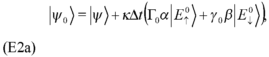


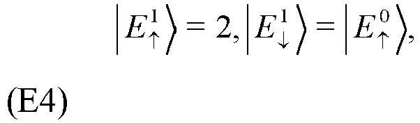


- The recovery process is R = {Û 0(1-P̂ 1),Û 1 P̂ 1}, where P is projection to the subspace of words after a photon loss error


- Even in the event of no photons being lost, the Kraus operator


- Assuming identical photon decay rates κ for both modes, the Kraus evolution operator in the absence of photon losses from either mode is Ê 00 = exp(-(n̂ 1 + n̂ 2)κΔt), so that Ê 00|Wσ 〉 = exp(-2κΔt)Wσ and the code words are unchanged. The correctable errors are still single photon losses, which can occur from either of the two modes, giving rise to different error words:


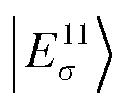


bosonic excitations ≤ 4. These are similar to the one-mode corrections, except that they involve creating states that are entangled between the two modes. This may be realizable using an experimental setup comprising entanglement between two cavitie. However, such an approach is likely to have lower fidelity than the equivalent one-mode operations. - As in the single mode code, the fidelity of the error correction may be determined by the rate of uncorrectable errors and for small κΔt this is dominated by two photon losses. There are three paths of two photon loss from the states of the two-mode code, compared to one path for the one mode code, Eqn. 6. Assuming equal κ, the rate of two photon losses via each path is the same, so the rate of uncorrectable errors for the two-mode code is three times larger than the one-mode code. Which code is preferable will depend on the fidelity of the no-jump correction for the one-mode code, as the need for this operation may be eliminated in the two-mode case.
Claims (14)
- A method of measuring and correcting errors within a circuit quantum electrodynamics system that includes a physical qubit (510) dispersively coupled to cavity resonator (520), wherein the cavity resonator has been previously configured with a state that is a superposition of a pair of codewords |W ↑〉 and |W ↓〉 selected from a class of binomial codes, wherein the pair of codewords |W ↑〉 and |W ↓〉 encode the state of the physical qubit in the state of the cavity resonator, and wherein the class of binomial codes is expressed by:
 measuring a parity of a first state of the cavity resonator, wherein the first state is a superposition of a plurality of photon number states, and wherein measuring the parity of the first state comprises measuring the photon number parity modulo N,where N is an integer greater than or equal to 2;subsequent to measuring the parity of the first state, measuring a parity of a second state of the cavity resonator, the second state being different from the first state, in order to detect an error syndrome of the cavity resonator, the error syndrome indicating that an error has occurred, wherein the error syndrome is associated with a superposition of a pair of error words, and wherein measuring the parity of the second state comprises measuring the photon number modulo N;applying a first drive waveform to the cavity resonator; andapplying a second drive waveform to the physical qubit concurrent with the application of the first drive waveform,wherein the first drive waveform and the second drive waveform are selected to correct the error indicated by the error syndrome by performing a unitary state transfer between the pair of codewords and the pair of error words , andwherein application of the first drive waveform and the second drive waveform cause said transitioning of the cavity resonator from the second state back to the first state.
 - The method of claim 1, wherein the first and second states are superpositions of the same plurality of photon number states, and wherein the first and second states have different amplitudes.
- The method of claim 2, wherein the first and second drive waveforms are configured based on a duration between measuring the parity of the first state and measuring the parity of the second state.
- The method of anyone of claims 1 to 3, wherein N equals
- The method of claim 1, wherein the first state is a superposition of two states that have equal mean photon numbers.
- The method of anyone of claims 1 to 5, wherein the first and second drive waveforms are selected from a computer readable medium storing a plurality of previously determined drive waveforms.
- The method of anyone of claims 1 to 3, or 5, wherein N is an integer greater than 2.
- A system, comprising:a circuit quantum electrodynamics system that includes a physical qubit (510) dispersively coupled to a cavity resonator;at least one computer readable medium storing a plurality of drive waveforms;at least one controller configured to:configure a state of the cavity resonator with a state that is a superposition of a pair of codewords |W ↑〉 and |W ↓〉 selected from a class of binomial codes, wherein the pair of codewords |W ↑〉 and |W ↓〉 encode the state of the physical qubit in the state of the cavity resonator, and wherein the class of binomial codes is expressed by:
 in which S and M are integers an |n〉 denotes a photon number state with n photons;measure a parity of a first state of the cavity resonator, wherein the first state is a superposition of a plurality of photon number states, and wherein measuring the parity of the first state comprises measuring the photon number parity modulo N, where N is an integer greater than or equal to 2;subsequent to measuring the parity of the first state, measure a parity of a second state of the cavity resonator, in order to detect an error syndrome of the cavity resonator, the error syndrome indicating that an error has occurred, wherein the error syndrome is associated with a superposition of a pair of error words, and wherein measuring the parity of the second state comprises measuring the photon number modulo N; andselect a first drive waveform and a second drive waveform from amongst the stored plurality of drive waveforms to correct the error indicated by the error syndrome by performing a unitary state transfer between the pair of codewords and the pair of error words and thereby transition the second state of the cavity resonator back to the first state; andat least one electromagnetic radiation source configured to:apply the first drive waveform to the cavity resonator; andapply the second drive waveform to the physical qubit concurrent with the application of the first drive waveform.
 - The system of claim 8, wherein the first and second drive waveforms are configured based on a duration between measuring the parity of the first state and measuring the parity of the second state.
- The system of claim 8 or 9, wherein N equals
- The system of claim 8 or 9, wherein N is an integer greater than 2.
- The system of any one of claims 8 to 11, wherein application of the first and second drive waveforms is configured to transition the cavity resonator from the second state back to the first state without passing through a ground state of the cavity resonator.
- The system of any one of claims 8 to 12, wherein the cavity resonator is a microwave cavity.
- The system of any one of claims 8 to 13, wherein the physical qubit is a transmon qubit.
Applications Claiming Priority (2)
| Application Number | Priority Date | Filing Date | Title |
|---|---|---|---|
| US201562263473P | 2015-12-04 | 2015-12-04 | |
| PCT/US2016/064609 WO2017151200A1 (en) | 2015-12-04 | 2016-12-02 | Techniques for quantum error correction using bosonic modes and related systems and methods |
Publications (3)
| Publication Number | Publication Date |
|---|---|
| EP3383793A1 EP3383793A1 (en) | 2018-10-10 |
| EP3383793A4 EP3383793A4 (en) | 2019-07-31 |
| EP3383793B1 true EP3383793B1 (en) | 2024-04-17 |
Family
ID=59743129
Family Applications (1)
| Application Number | Title | Priority Date | Filing Date |
|---|---|---|---|
| EP16892925.5A Active EP3383793B1 (en) | 2015-12-04 | 2016-12-02 | Techniques for quantum error correction using bosonic modes and related systems and methods |
Country Status (7)
| Country | Link |
|---|---|
| US (1) | US11037068B2 (en) |
| EP (1) | EP3383793B1 (en) |
| JP (1) | JP6947408B2 (en) |
| CN (1) | CN108290733B (en) |
| CA (1) | CA3004750C (en) |
| SG (1) | SG11201803912YA (en) |
| WO (1) | WO2017151200A1 (en) |
Families Citing this family (50)
| Publication number | Priority date | Publication date | Assignee | Title |
|---|---|---|---|---|
| JP2018513452A (en) | 2015-02-27 | 2018-05-24 | イェール ユニバーシティーYale University | Techniques and related systems and methods for universal quantum control of quantum coherent states |
| KR20170123657A (en) | 2015-02-27 | 2017-11-08 | 예일 유니버시티 | Oscillator control technology for quantum information processing and related systems and methods |
| CA2993006C (en) | 2015-07-24 | 2023-10-03 | Yale University | Techniques of oscillator state manipulation for quantum information processing and related systems and methods |
| SG11201803545QA (en) * | 2015-10-29 | 2018-05-30 | Google Llc | Removing leakage in a quantum bit |
| EP3414583A4 (en) | 2016-02-12 | 2019-10-30 | Yale University | CONTROL TECHNIQUES FOR QUANTUM SYSTEMS AND ASSOCIATED SYSTEMS AND METHODS |
| US10776709B2 (en) | 2016-11-10 | 2020-09-15 | Yale University | Generalized quantum channels |
| US10404287B2 (en) * | 2017-03-20 | 2019-09-03 | Microsoft Technology Licensing, Llc | Magic state distillation with low space overhead and asymptotic input count |
| WO2019156759A2 (en) * | 2018-01-05 | 2019-08-15 | Yale University | Robust quantum logical gates |
| JP7382069B2 (en) * | 2018-01-05 | 2023-11-16 | イェール ユニバーシティー | Hardware efficient fault-tolerant operation using superconducting circuits |
| US11782779B2 (en) | 2018-01-05 | 2023-10-10 | Yale University | Techniques for error correction of a logical qubit and related systems and methods |
| CN112654970B (en) | 2018-06-29 | 2025-01-17 | 耶鲁大学 | Quantum information processing using asymmetric error channels |
| FI20185847A1 (en) | 2018-10-10 | 2020-04-11 | Aalto Univ Foundation Sr | Method and arrangement for reading out the state of a qubit |
| US11995512B2 (en) | 2018-11-13 | 2024-05-28 | Atom Computing Inc. | Scalable neutral atom based quantum computing |
| US11580435B2 (en) | 2018-11-13 | 2023-02-14 | Atom Computing Inc. | Scalable neutral atom based quantum computing |
| US10504033B1 (en) | 2018-11-13 | 2019-12-10 | Atom Computing Inc. | Scalable neutral atom based quantum computing |
| CN111222644B (en) * | 2018-11-26 | 2023-09-26 | 华为技术有限公司 | A method of controlling qubits in superconducting chips and related equipment |
| SG11202109186VA (en) | 2019-03-01 | 2021-09-29 | Univ Yale | Techniques for quantum memory addressing and related systems and methods |
| WO2020181116A1 (en) * | 2019-03-05 | 2020-09-10 | Google Llc | Decoding errors using quantum subspace expansion |
| US11909451B2 (en) | 2019-03-28 | 2024-02-20 | Yale University | Error correction while maintaining bosonic nature of the system |
| US11556411B2 (en) | 2019-04-24 | 2023-01-17 | International Business Machines Corporation | Quantum code for reduced frequency collisions in qubit lattices |
| US11005574B2 (en) * | 2019-06-27 | 2021-05-11 | International Business Machines Corporation | Superconducting interposer for optical transduction of quantum information |
| US11971464B1 (en) | 2019-12-20 | 2024-04-30 | The United States Of America, Represented By The Secretary Of The Navy | Magnon excitation and detection systems, apparatus, and methods |
| US11403168B2 (en) | 2020-02-28 | 2022-08-02 | International Business Machines Corporation | Using superconducting microwave gyrator for parity detection of weak magnetic sources |
| EP4115351A4 (en) | 2020-03-02 | 2024-05-08 | Atom Computing Inc. | Scalable neutral atom based quantum computing |
| CN115516469B (en) | 2020-03-02 | 2026-05-01 | 原子计算公司 | Scalable neutral atom-based quantum computation |
| WO2021243079A1 (en) * | 2020-05-29 | 2021-12-02 | Google Llc | Characterization of time-correlated quantum errors through entanglement |
| FR3114672B1 (en) * | 2020-09-25 | 2023-12-08 | Centre Nat Rech Scient | System for autonomous stabilization of quantum states with predetermined parity for error correction |
| US11321627B1 (en) * | 2020-11-13 | 2022-05-03 | Amazon Technologies, Inc. | Fault-tolerant quantum hardware using hybrid acoustic-electrical qubits |
| US11468219B2 (en) | 2020-11-13 | 2022-10-11 | Amazon Technologies, Inc. | Toffoli gate preparation for a quantum hardware system comprising hybrid acoustic-electrical qubits |
| US11741279B2 (en) | 2020-11-13 | 2023-08-29 | Amazon Technologies, Inc. | Toffoli gate distillation from Toffoli magic states |
| US12093785B2 (en) | 2020-11-13 | 2024-09-17 | Amazon Technologies, Inc. | High-fidelity measurement of bosonic modes |
| CN114511093B (en) * | 2020-11-16 | 2023-06-09 | 中国人民解放军国防科技大学 | Simulation method of boson subsystem |
| US11580436B2 (en) | 2020-12-04 | 2023-02-14 | Amazon Technologies, Inc. | Stabilizer measurement decoding using additional edges to identify errors caused by cross-talk |
| US11836108B2 (en) | 2021-01-25 | 2023-12-05 | Red Hat, Inc. | Performing file differential operations on quantum files in a state of superposition |
| WO2022197781A1 (en) * | 2021-03-17 | 2022-09-22 | Friedlander Gregory | Process for dimensional manipulation using key fractal elements |
| JP2024513655A (en) * | 2021-03-19 | 2024-03-27 | ノール クアンティキ インコーポレイテッド | Systems, methods, and control instructions for simultaneously inhibiting bit-flip error types and phase-flip error types in a quantum subsystem |
| CN113157879A (en) * | 2021-03-25 | 2021-07-23 | 天津大学 | Computer medium for question-answering task matching based on quantum measurement |
| US11983601B2 (en) * | 2021-03-30 | 2024-05-14 | Amazon Technologies, Inc. | Hybrid bacon-shor surface codes in a concatenated cat-qubit architecture |
| US12014247B2 (en) | 2021-05-13 | 2024-06-18 | University Of Maryland, College Park | Systems and methods for compressed sensing measurement of long-range correlated noise |
| KR20230066842A (en) | 2021-11-08 | 2023-05-16 | 현대자동차주식회사 | Quantum state simulation method using a quantum computer and the quantum computer |
| JP2024541686A (en) * | 2021-12-06 | 2024-11-08 | イェール ユニバーシティー | Techniques for preparing fault-tolerant cluster states |
| US11748652B1 (en) * | 2021-12-10 | 2023-09-05 | Amazon Technologies, Inc. | Heralding of amplitude damping decay noise for quantum error correction |
| KR20240126442A (en) * | 2021-12-22 | 2024-08-20 | 예일 유니버시티 | Measurement-based fault-tolerant architecture for 4-legged cat code |
| EP4453810A4 (en) * | 2021-12-22 | 2025-07-23 | Univ Yale | QUANTUM ERROR CORRECTION TECHNIQUES USING MULTIMODAL LATTICE STATES AND CORRESPONDING SYSTEMS AND METHODS |
| US20260004170A1 (en) * | 2022-01-25 | 2026-01-01 | SavantX, Inc. | Active quantum memory systems and techniques for mitigating decoherence in a quantum computing device |
| CN116992967B (en) * | 2022-04-25 | 2025-08-08 | 本源量子计算科技(合肥)股份有限公司 | Initialization method of quantum bit reading cavity |
| EP4526813A4 (en) | 2022-05-19 | 2026-05-06 | Atom Computing Inc | DEVICES AND METHODS FOR CAVE-BASED CALCULATION |
| JP2024014126A (en) * | 2022-07-21 | 2024-02-01 | 国立大学法人 東京大学 | Information generation device and information generation method |
| US12093128B2 (en) * | 2022-11-30 | 2024-09-17 | Jpmorgan Chase Bank, N.A. | Systems and methods for efficient error mitigation in quantum circuit execution using parity checks and classical feedback |
| CN115792764B (en) * | 2022-11-30 | 2025-08-15 | 西北核技术研究所 | Analysis method for measuring electromagnetic pulse system error by transmission coefficient method |
Family Cites Families (19)
| Publication number | Priority date | Publication date | Assignee | Title |
|---|---|---|---|---|
| US7555263B1 (en) | 1999-10-21 | 2009-06-30 | Broadcom Corporation | Adaptive radio transceiver |
| US7498832B2 (en) * | 2007-08-03 | 2009-03-03 | Northrop Grumman Systems Corporation | Arbitrary quantum operations with a common coupled resonator |
| US7932514B2 (en) | 2008-05-23 | 2011-04-26 | International Business Machines Corporation | Microwave readout for flux-biased qubits |
| US7889992B1 (en) * | 2009-09-21 | 2011-02-15 | International Business Machines Corporation | Hybrid superconductor-optical quantum repeater |
| US8648331B2 (en) * | 2010-11-10 | 2014-02-11 | Microsoft Corporation | Coherent quantum information transfer between topological and conventional qubits |
| US8242799B2 (en) * | 2010-11-16 | 2012-08-14 | Northrop Grumman Systems Corporation | System and method for phase error reduction in quantum systems |
| US8508280B2 (en) | 2011-07-11 | 2013-08-13 | Northrop Grumman Systems Corporation | Qubit readout via resonant scattering of josephson solitons |
| US8918442B2 (en) * | 2012-08-22 | 2014-12-23 | International Business Machines Corporation | Reducing bias in hardware generated random numbers |
| US9018971B2 (en) * | 2012-10-26 | 2015-04-28 | Northrop Grumman Systems Corporation | Efficient resource state distillation |
| JP5992292B2 (en) * | 2012-10-30 | 2016-09-14 | 株式会社東芝 | Decoding device, method and program |
| US9286154B2 (en) * | 2013-06-07 | 2016-03-15 | Alcatel Lucent | Error correction for entangled quantum states |
| US10650319B2 (en) * | 2015-02-06 | 2020-05-12 | Northrop Grumman Systems Corporation | Flux control of qubit under resonant excitation |
| US9905999B2 (en) | 2015-02-26 | 2018-02-27 | California Institute Of Technology | Optical frequency divider based on an electro-optical-modulator frequency comb |
| KR20170123657A (en) * | 2015-02-27 | 2017-11-08 | 예일 유니버시티 | Oscillator control technology for quantum information processing and related systems and methods |
| CN104881268A (en) * | 2015-05-19 | 2015-09-02 | 南昌大学 | Optical photon random source device and random order extraction method |
| CA2993006C (en) | 2015-07-24 | 2023-10-03 | Yale University | Techniques of oscillator state manipulation for quantum information processing and related systems and methods |
| US10250271B2 (en) * | 2015-10-07 | 2019-04-02 | Kabushiki Kaisha Toshiba | Quantum computation apparatus and quantum computation method |
| EP3414583A4 (en) | 2016-02-12 | 2019-10-30 | Yale University | CONTROL TECHNIQUES FOR QUANTUM SYSTEMS AND ASSOCIATED SYSTEMS AND METHODS |
| US11782779B2 (en) | 2018-01-05 | 2023-10-10 | Yale University | Techniques for error correction of a logical qubit and related systems and methods |
-
2016
- 2016-12-02 CN CN201680070790.8A patent/CN108290733B/en active Active
- 2016-12-02 SG SG11201803912YA patent/SG11201803912YA/en unknown
- 2016-12-02 EP EP16892925.5A patent/EP3383793B1/en active Active
- 2016-12-02 US US15/781,233 patent/US11037068B2/en active Active
- 2016-12-02 WO PCT/US2016/064609 patent/WO2017151200A1/en not_active Ceased
- 2016-12-02 JP JP2018528315A patent/JP6947408B2/en active Active
- 2016-12-02 CA CA3004750A patent/CA3004750C/en active Active
Also Published As
| Publication number | Publication date |
|---|---|
| EP3383793A1 (en) | 2018-10-10 |
| US20200242500A1 (en) | 2020-07-30 |
| CA3004750A1 (en) | 2017-09-08 |
| EP3383793A4 (en) | 2019-07-31 |
| CN108290733B (en) | 2022-04-26 |
| US11037068B2 (en) | 2021-06-15 |
| WO2017151200A8 (en) | 2017-10-19 |
| CA3004750C (en) | 2024-04-16 |
| CN108290733A (en) | 2018-07-17 |
| JP6947408B2 (en) | 2021-10-13 |
| HK1254887A1 (en) | 2019-07-26 |
| JP2019501581A (en) | 2019-01-17 |
| WO2017151200A1 (en) | 2017-09-08 |
| KR20180090857A (en) | 2018-08-13 |
| SG11201803912YA (en) | 2018-06-28 |
Similar Documents
| Publication | Publication Date | Title |
|---|---|---|
| US11037068B2 (en) | Techniques for quantum error correction using bosonic modes and related systems and methods | |
| EP3325404B1 (en) | Techniques of oscillator state manipulation for quantum information processing and related systems and methods | |
| US11449384B2 (en) | Hardware-efficient fault-tolerant operations with superconducting circuits | |
| US7554080B2 (en) | Entanglement processes and system | |
| Chuang et al. | Experimental implementation of fast quantum searching | |
| KR20210024638A (en) | Quantum information processing with asymmetric error channels | |
| Ofek et al. | Demonstrating quantum error correction that extends the lifetime of quantum information | |
| DiVincenzo et al. | Decoherence: the obstacle to quantum computation | |
| Pittman et al. | Quantum computing using linear optics | |
| US20250356232A9 (en) | Measurement-based fault tolerant architecture for the 4-legged cat code | |
| HK1254887B (en) | Techniques for quantum error correction using bosonic modes and related systems and methods | |
| EP4428765A1 (en) | System for performing a quantum gate and operation of a quantum error correcting code using this quantum gate | |
| Teoh | Error detection in bosonic circuit quantum electrodynamics | |
| KR102963731B1 (en) | Techniques for quantum error correction using boson modes and related systems and methods | |
| Chuang et al. | The persistent quantum bit | |
| CA3241019A1 (en) | Techniques for quantum error correction using multimode grid states and related systems and methods | |
| Cussenot | Quantum memories for quantum networking and computing technologies | |
| KR20250123889A (en) | Dual-rail encoding technology for qubits and related systems and methods | |
| Ramette | Generating and protecting high fidelity multi-particle entangled states with atom-photon interactions | |
| WO2026027788A1 (en) | Methods and apparatus for generating quantum entanglement | |
| HK40041601B (en) | Hardware-efficient fault-tolerant operations with superconducting circuits | |
| HK40041601A (en) | Hardware-efficient fault-tolerant operations with superconducting circuits | |
| Steane | Extracting entropy from quantum computers | |
| Glancy | Topics in linear optical quantum computation | |
| Knill et al. | Concatenated codes for fault tolerant quantum computing |
Legal Events
| Date | Code | Title | Description |
|---|---|---|---|
| STAA | Information on the status of an ep patent application or granted ep patent |
Free format text: STATUS: THE INTERNATIONAL PUBLICATION HAS BEEN MADE |
|
| PUAI | Public reference made under article 153(3) epc to a published international application that has entered the european phase |
Free format text: ORIGINAL CODE: 0009012 |
|
| STAA | Information on the status of an ep patent application or granted ep patent |
Free format text: STATUS: REQUEST FOR EXAMINATION WAS MADE |
|
| 17P | Request for examination filed |
Effective date: 20180604 |
|
| AK | Designated contracting states |
Kind code of ref document: A1 Designated state(s): AL AT BE BG CH CY CZ DE DK EE ES FI FR GB GR HR HU IE IS IT LI LT LU LV MC MK MT NL NO PL PT RO RS SE SI SK SM TR |
|
| AX | Request for extension of the european patent |
Extension state: BA ME |
|
| RIN1 | Information on inventor provided before grant (corrected) |
Inventor name: ALBERT, VICTOR, V. Inventor name: SALMILEHTO, JUHA Inventor name: GIRVIN, STEVEN, M. Inventor name: JIANG, LIANG Inventor name: SILVERI, MATTI Inventor name: MICHAEL, MARIOS, H. Inventor name: BRIERLEY, RICHARD, T. |
|
| DAV | Request for validation of the european patent (deleted) | ||
| DAX | Request for extension of the european patent (deleted) | ||
| REG | Reference to a national code |
Ref country code: HK Ref legal event code: DE Ref document number: 1254887 Country of ref document: HK |
|
| A4 | Supplementary search report drawn up and despatched |
Effective date: 20190628 |
|
| RIC1 | Information provided on ipc code assigned before grant |
Ipc: G06N 10/00 20190101ALI20190624BHEP Ipc: B82Y 10/00 20110101AFI20190624BHEP Ipc: H01L 39/22 20060101ALI20190624BHEP |
|
| STAA | Information on the status of an ep patent application or granted ep patent |
Free format text: STATUS: EXAMINATION IS IN PROGRESS |
|
| 17Q | First examination report despatched |
Effective date: 20211011 |
|
| 17Q | First examination report despatched |
Effective date: 20211022 |
|
| REG | Reference to a national code |
Ref legal event code: R079 Ipc: G06N0010700000 Ref country code: DE Ref legal event code: R079 Ref document number: 602016087042 Country of ref document: DE Free format text: PREVIOUS MAIN CLASS: B82Y0010000000 Ipc: G06N0010700000 |
|
| GRAP | Despatch of communication of intention to grant a patent |
Free format text: ORIGINAL CODE: EPIDOSNIGR1 |
|
| STAA | Information on the status of an ep patent application or granted ep patent |
Free format text: STATUS: GRANT OF PATENT IS INTENDED |
|
| RIC1 | Information provided on ipc code assigned before grant |
Ipc: G06N 10/70 20220101AFI20231031BHEP |
|
| INTG | Intention to grant announced |
Effective date: 20231116 |
|
| GRAS | Grant fee paid |
Free format text: ORIGINAL CODE: EPIDOSNIGR3 |
|
| GRAA | (expected) grant |
Free format text: ORIGINAL CODE: 0009210 |
|
| STAA | Information on the status of an ep patent application or granted ep patent |
Free format text: STATUS: THE PATENT HAS BEEN GRANTED |
|
| AK | Designated contracting states |
Kind code of ref document: B1 Designated state(s): AL AT BE BG CH CY CZ DE DK EE ES FI FR GB GR HR HU IE IS IT LI LT LU LV MC MK MT NL NO PL PT RO RS SE SI SK SM TR |
|
| REG | Reference to a national code |
Ref country code: GB Ref legal event code: FG4D |
|
| P01 | Opt-out of the competence of the unified patent court (upc) registered |
Effective date: 20240315 |
|
| REG | Reference to a national code |
Ref country code: CH Ref legal event code: EP |
|
| REG | Reference to a national code |
Ref country code: IE Ref legal event code: FG4D Ref country code: DE Ref legal event code: R096 Ref document number: 602016087042 Country of ref document: DE |
|
| REG | Reference to a national code |
Ref country code: LT Ref legal event code: MG9D |
|
| REG | Reference to a national code |
Ref country code: NL Ref legal event code: MP Effective date: 20240417 |
|
| REG | Reference to a national code |
Ref country code: AT Ref legal event code: MK05 Ref document number: 1677953 Country of ref document: AT Kind code of ref document: T Effective date: 20240417 |
|
| PG25 | Lapsed in a contracting state [announced via postgrant information from national office to epo] |
Ref country code: NL Free format text: LAPSE BECAUSE OF FAILURE TO SUBMIT A TRANSLATION OF THE DESCRIPTION OR TO PAY THE FEE WITHIN THE PRESCRIBED TIME-LIMIT Effective date: 20240417 |
|
| PG25 | Lapsed in a contracting state [announced via postgrant information from national office to epo] |
Ref country code: NL Free format text: LAPSE BECAUSE OF FAILURE TO SUBMIT A TRANSLATION OF THE DESCRIPTION OR TO PAY THE FEE WITHIN THE PRESCRIBED TIME-LIMIT Effective date: 20240417 |
|
| PG25 | Lapsed in a contracting state [announced via postgrant information from national office to epo] |
Ref country code: IS Free format text: LAPSE BECAUSE OF FAILURE TO SUBMIT A TRANSLATION OF THE DESCRIPTION OR TO PAY THE FEE WITHIN THE PRESCRIBED TIME-LIMIT Effective date: 20240817 |
|
| PG25 | Lapsed in a contracting state [announced via postgrant information from national office to epo] |
Ref country code: BG Free format text: LAPSE BECAUSE OF FAILURE TO SUBMIT A TRANSLATION OF THE DESCRIPTION OR TO PAY THE FEE WITHIN THE PRESCRIBED TIME-LIMIT Effective date: 20240417 |
|
| PG25 | Lapsed in a contracting state [announced via postgrant information from national office to epo] |
Ref country code: HR Free format text: LAPSE BECAUSE OF FAILURE TO SUBMIT A TRANSLATION OF THE DESCRIPTION OR TO PAY THE FEE WITHIN THE PRESCRIBED TIME-LIMIT Effective date: 20240417 Ref country code: FI Free format text: LAPSE BECAUSE OF FAILURE TO SUBMIT A TRANSLATION OF THE DESCRIPTION OR TO PAY THE FEE WITHIN THE PRESCRIBED TIME-LIMIT Effective date: 20240417 |
|
| PG25 | Lapsed in a contracting state [announced via postgrant information from national office to epo] |
Ref country code: GR Free format text: LAPSE BECAUSE OF FAILURE TO SUBMIT A TRANSLATION OF THE DESCRIPTION OR TO PAY THE FEE WITHIN THE PRESCRIBED TIME-LIMIT Effective date: 20240718 |
|
| PG25 | Lapsed in a contracting state [announced via postgrant information from national office to epo] |
Ref country code: PT Free format text: LAPSE BECAUSE OF FAILURE TO SUBMIT A TRANSLATION OF THE DESCRIPTION OR TO PAY THE FEE WITHIN THE PRESCRIBED TIME-LIMIT Effective date: 20240819 |
|
| PG25 | Lapsed in a contracting state [announced via postgrant information from national office to epo] |
Ref country code: ES Free format text: LAPSE BECAUSE OF FAILURE TO SUBMIT A TRANSLATION OF THE DESCRIPTION OR TO PAY THE FEE WITHIN THE PRESCRIBED TIME-LIMIT Effective date: 20240417 |
|
| PG25 | Lapsed in a contracting state [announced via postgrant information from national office to epo] |
Ref country code: AT Free format text: LAPSE BECAUSE OF FAILURE TO SUBMIT A TRANSLATION OF THE DESCRIPTION OR TO PAY THE FEE WITHIN THE PRESCRIBED TIME-LIMIT Effective date: 20240417 |
|
| PG25 | Lapsed in a contracting state [announced via postgrant information from national office to epo] |
Ref country code: PL Free format text: LAPSE BECAUSE OF FAILURE TO SUBMIT A TRANSLATION OF THE DESCRIPTION OR TO PAY THE FEE WITHIN THE PRESCRIBED TIME-LIMIT Effective date: 20240417 |
|
| PG25 | Lapsed in a contracting state [announced via postgrant information from national office to epo] |
Ref country code: LV Free format text: LAPSE BECAUSE OF FAILURE TO SUBMIT A TRANSLATION OF THE DESCRIPTION OR TO PAY THE FEE WITHIN THE PRESCRIBED TIME-LIMIT Effective date: 20240417 |
|
| PG25 | Lapsed in a contracting state [announced via postgrant information from national office to epo] |
Ref country code: PT Free format text: LAPSE BECAUSE OF FAILURE TO SUBMIT A TRANSLATION OF THE DESCRIPTION OR TO PAY THE FEE WITHIN THE PRESCRIBED TIME-LIMIT Effective date: 20240819 Ref country code: PL Free format text: LAPSE BECAUSE OF FAILURE TO SUBMIT A TRANSLATION OF THE DESCRIPTION OR TO PAY THE FEE WITHIN THE PRESCRIBED TIME-LIMIT Effective date: 20240417 Ref country code: NO Free format text: LAPSE BECAUSE OF FAILURE TO SUBMIT A TRANSLATION OF THE DESCRIPTION OR TO PAY THE FEE WITHIN THE PRESCRIBED TIME-LIMIT Effective date: 20240717 Ref country code: LV Free format text: LAPSE BECAUSE OF FAILURE TO SUBMIT A TRANSLATION OF THE DESCRIPTION OR TO PAY THE FEE WITHIN THE PRESCRIBED TIME-LIMIT Effective date: 20240417 Ref country code: IS Free format text: LAPSE BECAUSE OF FAILURE TO SUBMIT A TRANSLATION OF THE DESCRIPTION OR TO PAY THE FEE WITHIN THE PRESCRIBED TIME-LIMIT Effective date: 20240817 Ref country code: HR Free format text: LAPSE BECAUSE OF FAILURE TO SUBMIT A TRANSLATION OF THE DESCRIPTION OR TO PAY THE FEE WITHIN THE PRESCRIBED TIME-LIMIT Effective date: 20240417 Ref country code: GR Free format text: LAPSE BECAUSE OF FAILURE TO SUBMIT A TRANSLATION OF THE DESCRIPTION OR TO PAY THE FEE WITHIN THE PRESCRIBED TIME-LIMIT Effective date: 20240718 Ref country code: FI Free format text: LAPSE BECAUSE OF FAILURE TO SUBMIT A TRANSLATION OF THE DESCRIPTION OR TO PAY THE FEE WITHIN THE PRESCRIBED TIME-LIMIT Effective date: 20240417 Ref country code: ES Free format text: LAPSE BECAUSE OF FAILURE TO SUBMIT A TRANSLATION OF THE DESCRIPTION OR TO PAY THE FEE WITHIN THE PRESCRIBED TIME-LIMIT Effective date: 20240417 Ref country code: BG Free format text: LAPSE BECAUSE OF FAILURE TO SUBMIT A TRANSLATION OF THE DESCRIPTION OR TO PAY THE FEE WITHIN THE PRESCRIBED TIME-LIMIT Effective date: 20240417 Ref country code: AT Free format text: LAPSE BECAUSE OF FAILURE TO SUBMIT A TRANSLATION OF THE DESCRIPTION OR TO PAY THE FEE WITHIN THE PRESCRIBED TIME-LIMIT Effective date: 20240417 Ref country code: RS Free format text: LAPSE BECAUSE OF FAILURE TO SUBMIT A TRANSLATION OF THE DESCRIPTION OR TO PAY THE FEE WITHIN THE PRESCRIBED TIME-LIMIT Effective date: 20240717 |
|
| PG25 | Lapsed in a contracting state [announced via postgrant information from national office to epo] |
Ref country code: DK Free format text: LAPSE BECAUSE OF FAILURE TO SUBMIT A TRANSLATION OF THE DESCRIPTION OR TO PAY THE FEE WITHIN THE PRESCRIBED TIME-LIMIT Effective date: 20240417 |
|
| REG | Reference to a national code |
Ref country code: DE Ref legal event code: R097 Ref document number: 602016087042 Country of ref document: DE |
|
| PG25 | Lapsed in a contracting state [announced via postgrant information from national office to epo] |
Ref country code: EE Free format text: LAPSE BECAUSE OF FAILURE TO SUBMIT A TRANSLATION OF THE DESCRIPTION OR TO PAY THE FEE WITHIN THE PRESCRIBED TIME-LIMIT Effective date: 20240417 |
|
| PG25 | Lapsed in a contracting state [announced via postgrant information from national office to epo] |
Ref country code: CZ Free format text: LAPSE BECAUSE OF FAILURE TO SUBMIT A TRANSLATION OF THE DESCRIPTION OR TO PAY THE FEE WITHIN THE PRESCRIBED TIME-LIMIT Effective date: 20240417 |
|
| PG25 | Lapsed in a contracting state [announced via postgrant information from national office to epo] |
Ref country code: RO Free format text: LAPSE BECAUSE OF FAILURE TO SUBMIT A TRANSLATION OF THE DESCRIPTION OR TO PAY THE FEE WITHIN THE PRESCRIBED TIME-LIMIT Effective date: 20240417 Ref country code: SK Free format text: LAPSE BECAUSE OF FAILURE TO SUBMIT A TRANSLATION OF THE DESCRIPTION OR TO PAY THE FEE WITHIN THE PRESCRIBED TIME-LIMIT Effective date: 20240417 |
|
| PG25 | Lapsed in a contracting state [announced via postgrant information from national office to epo] |
Ref country code: SM Free format text: LAPSE BECAUSE OF FAILURE TO SUBMIT A TRANSLATION OF THE DESCRIPTION OR TO PAY THE FEE WITHIN THE PRESCRIBED TIME-LIMIT Effective date: 20240417 |
|
| PG25 | Lapsed in a contracting state [announced via postgrant information from national office to epo] |
Ref country code: SM Free format text: LAPSE BECAUSE OF FAILURE TO SUBMIT A TRANSLATION OF THE DESCRIPTION OR TO PAY THE FEE WITHIN THE PRESCRIBED TIME-LIMIT Effective date: 20240417 Ref country code: SK Free format text: LAPSE BECAUSE OF FAILURE TO SUBMIT A TRANSLATION OF THE DESCRIPTION OR TO PAY THE FEE WITHIN THE PRESCRIBED TIME-LIMIT Effective date: 20240417 Ref country code: RO Free format text: LAPSE BECAUSE OF FAILURE TO SUBMIT A TRANSLATION OF THE DESCRIPTION OR TO PAY THE FEE WITHIN THE PRESCRIBED TIME-LIMIT Effective date: 20240417 Ref country code: EE Free format text: LAPSE BECAUSE OF FAILURE TO SUBMIT A TRANSLATION OF THE DESCRIPTION OR TO PAY THE FEE WITHIN THE PRESCRIBED TIME-LIMIT Effective date: 20240417 Ref country code: DK Free format text: LAPSE BECAUSE OF FAILURE TO SUBMIT A TRANSLATION OF THE DESCRIPTION OR TO PAY THE FEE WITHIN THE PRESCRIBED TIME-LIMIT Effective date: 20240417 Ref country code: CZ Free format text: LAPSE BECAUSE OF FAILURE TO SUBMIT A TRANSLATION OF THE DESCRIPTION OR TO PAY THE FEE WITHIN THE PRESCRIBED TIME-LIMIT Effective date: 20240417 |
|
| PLBE | No opposition filed within time limit |
Free format text: ORIGINAL CODE: 0009261 |
|
| STAA | Information on the status of an ep patent application or granted ep patent |
Free format text: STATUS: NO OPPOSITION FILED WITHIN TIME LIMIT |
|
| 26N | No opposition filed |
Effective date: 20250120 |
|
| PG25 | Lapsed in a contracting state [announced via postgrant information from national office to epo] |
Ref country code: SI Free format text: LAPSE BECAUSE OF FAILURE TO SUBMIT A TRANSLATION OF THE DESCRIPTION OR TO PAY THE FEE WITHIN THE PRESCRIBED TIME-LIMIT Effective date: 20240417 |
|
| PG25 | Lapsed in a contracting state [announced via postgrant information from national office to epo] |
Ref country code: MC Free format text: LAPSE BECAUSE OF FAILURE TO SUBMIT A TRANSLATION OF THE DESCRIPTION OR TO PAY THE FEE WITHIN THE PRESCRIBED TIME-LIMIT Effective date: 20240417 |
|
| REG | Reference to a national code |
Ref country code: CH Ref legal event code: PL |
|
| PG25 | Lapsed in a contracting state [announced via postgrant information from national office to epo] |
Ref country code: LU Free format text: LAPSE BECAUSE OF NON-PAYMENT OF DUE FEES Effective date: 20241202 |
|
| PG25 | Lapsed in a contracting state [announced via postgrant information from national office to epo] |
Ref country code: SE Free format text: LAPSE BECAUSE OF FAILURE TO SUBMIT A TRANSLATION OF THE DESCRIPTION OR TO PAY THE FEE WITHIN THE PRESCRIBED TIME-LIMIT Effective date: 20240417 |
|
| REG | Reference to a national code |
Ref country code: BE Ref legal event code: MM Effective date: 20241231 |
|
| PG25 | Lapsed in a contracting state [announced via postgrant information from national office to epo] |
Ref country code: BE Free format text: LAPSE BECAUSE OF NON-PAYMENT OF DUE FEES Effective date: 20241231 |
|
| PG25 | Lapsed in a contracting state [announced via postgrant information from national office to epo] |
Ref country code: CH Free format text: LAPSE BECAUSE OF NON-PAYMENT OF DUE FEES Effective date: 20241231 |
|
| PG25 | Lapsed in a contracting state [announced via postgrant information from national office to epo] |
Ref country code: IE Free format text: LAPSE BECAUSE OF NON-PAYMENT OF DUE FEES Effective date: 20241202 |
|
| PGFP | Annual fee paid to national office [announced via postgrant information from national office to epo] |
Ref country code: GB Payment date: 20251229 Year of fee payment: 10 |
|
| PGFP | Annual fee paid to national office [announced via postgrant information from national office to epo] |
Ref country code: IT Payment date: 20251219 Year of fee payment: 10 |
|
| PGFP | Annual fee paid to national office [announced via postgrant information from national office to epo] |
Ref country code: FR Payment date: 20251226 Year of fee payment: 10 |
|
| PG25 | Lapsed in a contracting state [announced via postgrant information from national office to epo] |
Ref country code: CY Free format text: LAPSE BECAUSE OF FAILURE TO SUBMIT A TRANSLATION OF THE DESCRIPTION OR TO PAY THE FEE WITHIN THE PRESCRIBED TIME-LIMIT; INVALID AB INITIO Effective date: 20161202 |
|
| PGFP | Annual fee paid to national office [announced via postgrant information from national office to epo] |
Ref country code: DE Payment date: 20251229 Year of fee payment: 10 |