EP3382962A1 - Method for managing active flows in a communication network by a network element, and corresponding network element - Google Patents
Method for managing active flows in a communication network by a network element, and corresponding network element Download PDFInfo
- Publication number
- EP3382962A1 EP3382962A1 EP17305376.0A EP17305376A EP3382962A1 EP 3382962 A1 EP3382962 A1 EP 3382962A1 EP 17305376 A EP17305376 A EP 17305376A EP 3382962 A1 EP3382962 A1 EP 3382962A1
- Authority
- EP
- European Patent Office
- Prior art keywords
- devices
- service
- services
- max
- priority
- Prior art date
- Legal status (The legal status is an assumption and is not a legal conclusion. Google has not performed a legal analysis and makes no representation as to the accuracy of the status listed.)
- Withdrawn
Links
- 238000004891 communication Methods 0.000 title claims abstract description 48
- 238000000034 method Methods 0.000 title claims description 26
- 238000010586 diagram Methods 0.000 description 14
- 238000007726 management method Methods 0.000 description 14
- 239000013598 vector Substances 0.000 description 11
- 230000006870 function Effects 0.000 description 10
- 238000005457 optimization Methods 0.000 description 9
- 230000008859 change Effects 0.000 description 8
- 238000012545 processing Methods 0.000 description 5
- 230000009471 action Effects 0.000 description 4
- 238000004590 computer program Methods 0.000 description 4
- 230000003993 interaction Effects 0.000 description 3
- 238000012986 modification Methods 0.000 description 3
- 230000004048 modification Effects 0.000 description 3
- 238000005516 engineering process Methods 0.000 description 2
- 239000000835 fiber Substances 0.000 description 2
- 238000013507 mapping Methods 0.000 description 2
- 230000008569 process Effects 0.000 description 2
- 230000003044 adaptive effect Effects 0.000 description 1
- 238000013459 approach Methods 0.000 description 1
- 238000002716 delivery method Methods 0.000 description 1
- 230000002068 genetic effect Effects 0.000 description 1
- 230000000670 limiting effect Effects 0.000 description 1
- 230000007246 mechanism Effects 0.000 description 1
- 230000006855 networking Effects 0.000 description 1
- 230000000750 progressive effect Effects 0.000 description 1
- 239000007787 solid Substances 0.000 description 1
- 230000007704 transition Effects 0.000 description 1
Images




Classifications
-
- H—ELECTRICITY
- H04—ELECTRIC COMMUNICATION TECHNIQUE
- H04L—TRANSMISSION OF DIGITAL INFORMATION, e.g. TELEGRAPHIC COMMUNICATION
- H04L47/00—Traffic control in data switching networks
- H04L47/70—Admission control; Resource allocation
- H04L47/80—Actions related to the user profile or the type of traffic
- H04L47/803—Application aware
-
- H—ELECTRICITY
- H04—ELECTRIC COMMUNICATION TECHNIQUE
- H04L—TRANSMISSION OF DIGITAL INFORMATION, e.g. TELEGRAPHIC COMMUNICATION
- H04L41/00—Arrangements for maintenance, administration or management of data switching networks, e.g. of packet switching networks
- H04L41/50—Network service management, e.g. ensuring proper service fulfilment according to agreements
-
- H—ELECTRICITY
- H04—ELECTRIC COMMUNICATION TECHNIQUE
- H04L—TRANSMISSION OF DIGITAL INFORMATION, e.g. TELEGRAPHIC COMMUNICATION
- H04L47/00—Traffic control in data switching networks
- H04L47/70—Admission control; Resource allocation
-
- H—ELECTRICITY
- H04—ELECTRIC COMMUNICATION TECHNIQUE
- H04N—PICTORIAL COMMUNICATION, e.g. TELEVISION
- H04N21/00—Selective content distribution, e.g. interactive television or video on demand [VOD]
- H04N21/20—Servers specifically adapted for the distribution of content, e.g. VOD servers; Operations thereof
- H04N21/23—Processing of content or additional data; Elementary server operations; Server middleware
- H04N21/24—Monitoring of processes or resources, e.g. monitoring of server load, available bandwidth, upstream requests
- H04N21/2402—Monitoring of the downstream path of the transmission network, e.g. bandwidth available
-
- H—ELECTRICITY
- H04—ELECTRIC COMMUNICATION TECHNIQUE
- H04N—PICTORIAL COMMUNICATION, e.g. TELEVISION
- H04N21/00—Selective content distribution, e.g. interactive television or video on demand [VOD]
- H04N21/40—Client devices specifically adapted for the reception of or interaction with content, e.g. set-top-box [STB]; Operations thereof
- H04N21/43—Processing of content or additional data, e.g. demultiplexing additional data from a digital video stream; Elementary client operations, e.g. monitoring of home network or synchronising decoder's clock; Client middleware
- H04N21/436—Interfacing a local distribution network, e.g. communicating with another STB or one or more peripheral devices inside the home
- H04N21/43615—Interfacing a Home Network, e.g. for connecting the client to a plurality of peripherals
-
- H—ELECTRICITY
- H04—ELECTRIC COMMUNICATION TECHNIQUE
- H04N—PICTORIAL COMMUNICATION, e.g. TELEVISION
- H04N21/00—Selective content distribution, e.g. interactive television or video on demand [VOD]
- H04N21/40—Client devices specifically adapted for the reception of or interaction with content, e.g. set-top-box [STB]; Operations thereof
- H04N21/43—Processing of content or additional data, e.g. demultiplexing additional data from a digital video stream; Elementary client operations, e.g. monitoring of home network or synchronising decoder's clock; Client middleware
- H04N21/442—Monitoring of processes or resources, e.g. detecting the failure of a recording device, monitoring the downstream bandwidth, the number of times a movie has been viewed, the storage space available from the internal hard disk
- H04N21/44209—Monitoring of downstream path of the transmission network originating from a server, e.g. bandwidth variations of a wireless network
-
- H—ELECTRICITY
- H04—ELECTRIC COMMUNICATION TECHNIQUE
- H04N—PICTORIAL COMMUNICATION, e.g. TELEVISION
- H04N21/00—Selective content distribution, e.g. interactive television or video on demand [VOD]
- H04N21/60—Network structure or processes for video distribution between server and client or between remote clients; Control signalling between clients, server and network components; Transmission of management data between server and client, e.g. sending from server to client commands for recording incoming content stream; Communication details between server and client
- H04N21/63—Control signaling related to video distribution between client, server and network components; Network processes for video distribution between server and clients or between remote clients, e.g. transmitting basic layer and enhancement layers over different transmission paths, setting up a peer-to-peer communication via Internet between remote STB's; Communication protocols; Addressing
- H04N21/647—Control signaling between network components and server or clients; Network processes for video distribution between server and clients, e.g. controlling the quality of the video stream, by dropping packets, protecting content from unauthorised alteration within the network, monitoring of network load, bridging between two different networks, e.g. between IP and wireless
- H04N21/64784—Data processing by the network
-
- H—ELECTRICITY
- H04—ELECTRIC COMMUNICATION TECHNIQUE
- H04L—TRANSMISSION OF DIGITAL INFORMATION, e.g. TELEGRAPHIC COMMUNICATION
- H04L41/00—Arrangements for maintenance, administration or management of data switching networks, e.g. of packet switching networks
- H04L41/08—Configuration management of networks or network elements
- H04L41/0894—Policy-based network configuration management
Definitions
- the present disclosure generally relates to the bandwidth and policy management, for instance in the context of a domestic or business network.
- the disclosure concerns a method to be implemented at a network element adapted to be connected to a communication network comprising a set of devices, said devices being configured to receive one set of available services, wherein said method comprises:
- a bandwidth for a flow associated with one of said couples can be obtained from a range of allowable bitrates for said flow between the service and the device of said couple.
- the range of allowable bit-rates for said flow between the service and the device of said couple can be defined by the range [Max (bs.min i , bd.min j ); Min (bs.max i , bd.max j )], wherein:
- the bandwidth for a flow associated with one of said couples obtained from the range [Max (bs.min i , bd.min j ); Min (bs.max i , bd.max j )], can depend on a bandwidth manager policy associated with said communication network.
- said bandwidth manager policy associated with said communication network can belong to the following group of policies comprising:
- allowing the identified one or more allowable flows can be performed periodically.
- allowing the identified one or more allowable flows can be performed based on a network event.
- said network event can belong to the following group of network events comprising:
- the network element can be arranged in a gateway.
- the present disclosure further concerns a network element adapted to be connected to a communication network comprising a set of devices, said devices being configured to receive one set of available services, wherein said network element comprises at least one memory and one or more processors configured to:
- the present disclosure further concerns a network element adapted to be connected to a communication network comprising a set of devices, said devices being configured to receive one set of available services, wherein the network element is a bandwidth manager configured to:
- a bandwidth for a flow associated with one of said couples can be obtained from a range of allowable bitrates for said flow between the service and the device of said couple.
- the range of allowable bit-rates for said flow between the service and the device of said couple (S i , D j ) can be defined by the range [Max (bs.min i , bd.min j ); Min (bs.max i , bd.max j )], wherein:
- the bandwidth for a flow associated with one of said couples obtained from the range [Max (bs.min i , bd.min j ); Min (bs.max i , bd.max j )], can depend on a bandwidth manager policy associated with said communication network.
- said bandwidth manager policy associated with said communication network can belong to the following group of policies comprising:
- the network element can be arranged in a gateway.
- the present disclosure further concerns a non-transitory program storage device, readable by a computer, tangibly embodying a program of instructions executable by the computer to perform a method to be implemented at a network element adapted to be connected to a communication network comprising a set of devices, said devices being configured to receive one set of available services, wherein said method comprises:
- the present disclosure also concerns a computer program product stored on a non-transitory computer readable medium and comprising program code instructions executable by a processor for implementing a method to be implemented at a network element adapted to be connected to a communication network comprising a set of devices, said devices being configured to receive one set of available services, wherein said method comprises:
- the method according to the disclosure may be implemented in software on a programmable device. It may be implemented solely in hardware or in software, or in a combination thereof.
- Some processes implemented by elements of the present disclosure may be computer implemented. Accordingly, such elements may take the form of an entirely hardware embodiment, an entirely software embodiment (including firmware, resident software, micro-code, etc.) or an embodiment combining software and hardware aspects that may all generally be referred to herein as "circuit", “module” or “system”. Furthermore, such elements may take the form of a computer program product embodied in any tangible medium of expression having computer usable program code embodied in the medium.
- a tangible carrier medium may comprise a storage medium such as a floppy disk, a CD-ROM, a hard disk drive, a magnetic tape device or a solid state memory device and the like.
- the disclosure thus provides a computer-readable program comprising computer-executable instructions to enable a computer to perform the method aforementioned.
- processor or “controller” should not be construed to refer exclusively to hardware capable of executing software, and may implicitly include, without limitation, digital signal processor (DSP) hardware, read only memory (ROM) for storing software, random access memory (RAM), and nonvolatile storage.
- DSP digital signal processor
- ROM read only memory
- RAM random access memory
- any element expressed as a means and/or module for performing a specified function is intended to encompass any way of performing that function including, for example, a) a combination of circuit elements that performs that function or b) software in any form, including, therefore, firmware, microcode or the like, combined with appropriate circuitry for executing that software to perform the function. It is thus regarded that any means that can provide those functionalities are equivalent to those shown herein.
- FIG 1 is a schematic diagram of an exemplary network infrastructure 1 wherein the present principles can be implemented.
- the network infrastructure 1 can comprise a network element 100 (such as a gateway or a bridge), one or more devices 10 and one or more servers 40 delivering one or more services Si, as further shown in Figure 4 .
- the devices 10 (such as, a portable media device, a mobile phone, a tablet, a Set Top Box, a laptop, a TV set, etc.) are, for instance, in communication with the gateway 100 through a local area network LAN 20 (e.g., via cable or wireless technologies such WiFi).
- a local area network LAN 20 e.g., via cable or wireless technologies such WiFi.
- the gateway 100 can further be in communication with the remote servers 40 via a wide area network WAN 30 (such as Internet) (e.g.; via cable, optic fiber, xDSL, satellite, LTE, 3G/4G/5G technologies, etc.). It should be understood that further apparatuses (not shown) can be arranged between devices 10 and gateway 100 and between gateway 100 and remote servers 40.
- WAN 30 such as Internet
- further apparatuses can be arranged between devices 10 and gateway 100 and between gateway 100 and remote servers 40.
- the gateway 100 (which can be any type of broadband gateway such as cable, xDSL, fiber or wireless) comprises:
- the gateway can further comprise a bandwidth manager configured to determine a number of flows between the services Si delivered by the servers 40 and the devices 10 D j , from the implementation of the method shown in Figure 3 compliant with the present principles. It should be understood that, in a variant compliant with the present principles, the bandwidth manager can be a standalone network element or can be arranged in another network element (for instance located in the WAN 30) distinct from the gateway.
- the method 300 can comprise:
- the bandwidth manager 160 running on the gateway 100, can be configured to activate the maximum number of downlink flows, taking into account the set of flow priorities (for instance given by a user), knowing that the sum of the bandwidths of the activated downlink flows needs to be lower than the available downlink bandwidth B associated with the communication network 20.
- the one or more steps of the method 300 can be performed periodically (such as every 30 seconds) or based on a network event, such as:
- the periodicity of the allocation can, for instance, depend, among other factors, on the processing resources available at the gateway 100.
- the goal of the bandwidth manager 160 of the gateway 100 can be to activate the maximum number of downlink flows, taking into account the set of flow priorities (e.g. given by the user) and knowing that the sum of the bandwidths of the active flows needs to be lower than the available downlink bandwidth B.
- the bandwidth manager 160 needs to solve an optimization problem that can be mathematically defined as follows:
- This bandwidth management optimization problem can be considered as the 0-1 Knapsack optimization problem as above described, so that a solution to the 0-1 Knapsack problem can provide a solution to said bandwidth management optimization problem.
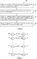
- Figure 4 graphically illustrates the mapping of the bandwidth management problem into the 0-1 Knapsack problem. For sake of clarity, only some possible flows between a service S i and a device D j are shown.
- Vs i vs i 0 , vs i 1 , ⁇ , vs ik , ⁇ , vs iK ⁇ 1 , where the priority vs ik ⁇ ⁇ 0,1,..., 100 ⁇ for example.
- Vs i vs i 0 , vs i 1 , ⁇ , vs ik , ⁇ , vs iK ⁇ 1 , where the priority vs ik ⁇ ⁇ 0,1,..., 100 ⁇ for example.
- other values can be used.
- the set of features of the service to consider can be:
- the set of n priorities ps j corresponding to the n services, can be aggregated into the vector P s of dimension n.
- Vd j vd j 0 , vd j 1 , ⁇ , vd jk , ⁇ , vd jK ⁇ 1 where the priority vd jk ⁇ ⁇ 0,1,..., 100 ⁇ for example.
- the set of features of the devices to consider can be:
- the set of m priorities pd j corresponding to the m services, can be aggregated into a vector P d of dimension m.
- the bandwidth b ij required for a downlink flow between a service S i and a device D j can be obtained from the range of allowable bit-rates [Max (bs.min i , bd.min j ); Min (bs.max i , bd.max j )] based, for instance, on a bandwidth manager policy associated with the LAN 20.
- Some examples of the bandwidth manager policy can be:
- the Multi-Tenancy principle (also known as Slicing) relies on sharing the network control among several administrators, among them an end user with administrator rights at home (so called HNA or Home Network Administrator), an ISP (Internet Service Provider), and other service providers.
- HNA Home Network Administrator
- ISP Internet Service Provider
- SDN Software Defined Networking
- NBI Northbound Application Programming Interfaces
- the local network 20 is considered as a multi-tenant network, wherein at least two tenants are present: the Home Network Administrator (HNA) and the Internet Service Provider (ISP). Additional tenants might be Over the Top (OTT) and Internet of Things (IoT) service providers (two additional tenants Tenant 1 and Tenant 2 are shown in Figure 6 ). The tenants are allowed to have higher and differentiated levels of control over the slices of the available resources.
- the southbound multi-tenancy architecture is implemented, wherein each tenant - except the HNA-owns his own controller and shares the common forwarding elements of the local network 20.
- the HNA Since the HNA has no access to the Southbound API, the HNA communicates his preferences to the other controllers, e.g., the ISP controller, through a dedicated interface. For example, the HNA can use an application on his smart phone (or tablet, computer, etc.) to modify and configure his profile and preferences.
- the HNA tenant has a consultative role about the control of the slices assigned to each service the user has subscribed to but he does not have a direct control of the slices, the control of the slices is the service providers' responsibility.
- FIG 8 depicts an illustrative, but non limitative, example of implementation of the present principles on smart phone device in reference to the schematic diagram shown in Figure 6 .
- a home network 20 is considered which comprises a gateway 100 and four devices 10 (such as a smart TV, a smart phone, a portable PC, a desktop PC).
- devices 10 such as a smart TV, a smart phone, a portable PC, a desktop PC.
- Four users can use the four devices.
- a smart-phone application 501 can be implemented on a smart-phone 500 (belonging to the home network) to display to the HNA an ordered list 502 of icons 510 arranged in column, each icon 510 representing a distinct service as shown in Figure 8 .
- the icon (i.e. the corresponding service) at the top of the column has the highest priority and the icon (i.e. the corresponding service) at the bottom of the column has the lowest priority.
- the HNA has the possibility to modify the proposed order for the services by moving the icons 510 in the column, for instance by interaction with the touch screen of the smart-phone 500, as shown in Figure 8 . Two services having the same priority can be arranged on a same row.
- the smart-phone application can then convert the displayed ordered list of service icons into an Event-Condition-Action (ECA) policy rule, as follows:
- ECA Event-Condition-Action
- This ECA policy rule can be stored into a policy file that can be read by the ISP controller which needs to translate the ECA policy rule into a set of numerical priorities as previously described.
- the ISP controller can be embedded within the gateway 100.
- the smart-phone application 501 can further to display to the HNA an ordered list 503 of icons 510 arranged in column, each icon 510 representing a distinct device 10 of the considered home network.
- the icon (i.e. the corresponding device) at the top of the column has the highest priority and the icon (i.e. the corresponding device) at the bottom of the column has the lowest priority.
- the HNA has also the ability to change the proposed order for the devices by moving the icons 510 in the column.
- the smart-phone application can convert the displayed ordered list of device icons into an ECA policy rule, as follows:
- the right side of Figure 9 shows the update of the ordered list of priorities of the set of devices after, for instance, one HNA's interaction (e.g. thanks to the touch screen by sliding icons to a desired position in the list).
- Figure 10 shows an evolution of active flows from an initial priority status (on the left side) to a final priority status (on the right side) with reference to the conditions of Figure 8 .
- Dad arrives at Home and wishes to watch a film from Netflix on the Smart TV.
- Daughter gives way the Smart TV to Dad and switches the YouTube stream to her smart phone.
- the sequence of events of Figure 10 can be translated by the HNA controller (which can be embedded within the gateway 100) into an ECA policy rule as follows to be handled by the ISP controller:
- the HNA can have the possibility to modify on the fly the flow priorities of the solution produced by the bandwidth manager solving the bandwidth management optimization problem. This would mean that the sets of service and device priorities (Ps, Pd), used as input for solving the bandwidth management optimization problem, do not represent the user wishes in the present context.
- the HNA can be allowed to have direct access to the Southbound API as shown in Figure 7 .
- the HNA is provided by the service provider with a standard profile that the HNA can modify.
- the standard profile corresponds to an average user and it contains the priority settings previously described.
- the ISP controller needs to verify that the HNA settings are valid. Therefore, interaction between the HNA and ISP controllers can be required.
- the HNA can get access to the Southbound API through the ISP controller.
- the difference with the previous variant is that the HNA has access only to the settings of the services provided by the ISP and has no direct access to the settings of the services provided by the other tenants.
- the bandwidth management method 300 can allow to activate the maximum number of flows, taking into account the set of flow priorities (for instance given by a user or by an operator), knowing that the sum of the bandwidths of the active flows needs to be lower than the available downlink bandwidth B.
- modules can correspond to functional modules, which may or may not correspond to distinguishable physical units.
- a plurality of such modules may be associated in a unique component or circuit, or correspond to software functionalities.
- a module may potentially be composed of separate physical entities or software functionalities.
- each block in the flowchart or block diagrams may represent a module, segment, or portion of code, which comprises one or more executable instructions for implementing the specified logical function(s).
- the functions noted in the block may occur out of the order noted in the figures. For example, two blocks shown in succession may, in fact, be executed substantially concurrently, or the blocks may sometimes be executed in the reverse order, or blocks may be executed in an alternative order, depending upon the functionality involved.
Landscapes
- Engineering & Computer Science (AREA)
- Signal Processing (AREA)
- Computer Networks & Wireless Communication (AREA)
- Multimedia (AREA)
- Databases & Information Systems (AREA)
- Computer Security & Cryptography (AREA)
- Data Exchanges In Wide-Area Networks (AREA)
- Telephonic Communication Services (AREA)
Abstract
Network element (100) adapted to be connected to a communication network comprising a set of devices, said devices being configured to receive one set of available services,
wherein the network element is a bandwidth manager (160) configured to:
- obtain, for couples defined by a service of the set of services and a device of the set of devices, a bandwidth for each flow between the service and the device of said couples;
- obtain a priority for the flows to be delivered between the services and the devices of said couples;
- solve a 0-1 Knapsack problem by applying the obtained bandwidths and priorities and by considering an available downlink bandwidth associated with said communication network, to identify one or more allowable flows to be delivered between services of the set of services and devices of the set of devices;
- allow the identified one or more allowable flows to be delivered to the corresponding devices of said communication network.
wherein the network element is a bandwidth manager (160) configured to:
- obtain, for couples defined by a service of the set of services and a device of the set of devices, a bandwidth for each flow between the service and the device of said couples;
- obtain a priority for the flows to be delivered between the services and the devices of said couples;
- solve a 0-1 Knapsack problem by applying the obtained bandwidths and priorities and by considering an available downlink bandwidth associated with said communication network, to identify one or more allowable flows to be delivered between services of the set of services and devices of the set of devices;
- allow the identified one or more allowable flows to be delivered to the corresponding devices of said communication network.
Description
- The present disclosure generally relates to the bandwidth and policy management, for instance in the context of a domestic or business network.
- This section is intended to introduce the reader to various aspects of art, which may be related to various aspects of the present disclosure that are described and/or claimed below. This discussion is believed to be helpful in providing the reader with background information to facilitate a better understanding of the various aspects of the present disclosure. Accordingly, it should be understood that these statements are to be read in this light, and not as admissions of prior art.
- In a home network, multiple users can run diverse applications using different devices to access a given set of services. In one hand, the number of networked devices at home and the bandwidth demand steadily increase, and in the other hand, the bandwidth of the downlink to the home network has remained roughly constant. As a result, application performance in home networks has become highly unpredictable with many home users suffering from poor Quality of Experience.
- There is then a need of a mechanism for managing bandwidth in a communication network, such as a home or business network, to enhance user experience.
- The disclosure concerns a method to be implemented at a network element adapted to be connected to a communication network comprising a set of devices, said devices being configured to receive one set of available services,
wherein said method comprises: - obtaining, for couples defined by a service of the set of services and a device of the set of devices, a bandwidth for each flow between the service and the device of said couples;
- obtaining a priority for the flows to be delivered between the services and the devices of said couples;
- solving a 0-1 Knapsack problem by applying the obtained bandwidths and priorities and by considering an available downlink bandwidth associated with said communication network, to identify one or more allowable flows to be delivered between services of the set of services and devices of the set of devices;
- allowing the identified one or more allowable flows to be delivered to the corresponding devices of said communication network.
- In an embodiment of the present principles, a bandwidth for a flow associated with one of said couples can be obtained from a range of allowable bitrates for said flow between the service and the device of said couple.
- In an embodiment of the present principles, the range of allowable bit-rates for said flow between the service and the device of said couple (Si, Dj) can be defined by the range [Max (bs.mini, bd.minj); Min (bs.maxi, bd.maxj)], wherein:
- [bs.mini, bs.maxi] is the range of bitrates available from the service Si of said couple (Si, Dj)
- [bd.minj, bd.maxj] is the range of bitrates supported by the device Dj of said couple (Si, Dj).
- In an embodiment of the present principles, the bandwidth for a flow associated with one of said couples, obtained from the range [Max (bs.mini, bd.minj); Min (bs.maxi, bd.maxj)], can depend on a bandwidth manager policy associated with said communication network.
- In an embodiment of the present principles, said bandwidth manager policy associated with said communication network can belong to the following group of policies comprising:
- priority to fairness;
- priority to quality;
- priority to user preferences.
- In an embodiment of the present principles, allowing the identified one or more allowable flows can be performed periodically.
- In an embodiment of the present principles, allowing the identified one or more allowable flows can be performed based on a network event.
- In an embodiment of the present principles, said network event can belong to the following group of network events comprising:
- a change in the allowed flows;
- a change in the available downlink bandwidth associated with said communication network;
- a change in one or more priorities of the allowable flows by a user input.
- In an embodiment of the present principles, a priority pij for a flow between the service Si and the device Dj of said couples can be defined by:

- psi is the priority associated with the service Si
- pdj is the priority associated with the device Dj.
- In an embodiment of the present principles, a priority pij for a flow between the service Si and the device Dj of said couples can be defined by:

- psi is the priority associated with the service Si
- pdj is the priority associated with the device Dj
- C1 and C2 are two constants defined by 0 ≤ C1,C2 ≤ 1 and C1+C2 ≤ 1.
- In an embodiment of the present principles, the priority psi associated with the service Si can be defined by:

- K is a number of features associated with the service Si
- vsik is a priority associated with the service Si for a feature k amongst the K features of the service Si.
- In an embodiment of the present principles, the priority pdj associated with the device Dj can be defined by:

- K is a number of attributes associated with the device Dj
- vdjk is a priority associated with the device Dj for an attribute k amongst the K attributes of the device Dj.
- In an embodiment of the present principles, the network element can be arranged in a gateway.
- Besides, the present disclosure further concerns a network element adapted to be connected to a communication network comprising a set of devices, said devices being configured to receive one set of available services,
wherein said network element comprises at least one memory and one or more processors configured to: - obtain, for couples defined by a service of the set of services and a device of the set of devices, a bandwidth for each flow between the service and the device of said couples;
- obtain a priority for the flows to be delivered between the services and the devices of said couples;
- solve a 0-1 Knapsack problem by applying the obtained bandwidths and priorities and by considering an available downlink bandwidth associated with said communication network, to identify one or more allowable flows to be delivered between services of the set of services and devices of the set of devices;
- allow the identified one or more allowable flows to be delivered to the corresponding devices of said communication network.
- Besides, the present disclosure further concerns a network element adapted to be connected to a communication network comprising a set of devices, said devices being configured to receive one set of available services,
wherein the network element is a bandwidth manager configured to: - obtain, for couples defined by a service of the set of services and a device of the set of devices, a bandwidth for each flow between the service and the device of said couples;
- obtain a priority for the flows to be delivered between the services and the devices of said couples;
- solve a 0-1 Knapsack problem by applying the obtained bandwidths and priorities and by considering an available downlink bandwidth associated with said communication network, to identify one or more allowable flows to be delivered between services of the set of services and devices of the set of devices;
- allow the identified one or more allowable flows to be delivered to the corresponding devices of said communication network.
- In an embodiment of the present principles, a bandwidth for a flow associated with one of said couples can be obtained from a range of allowable bitrates for said flow between the service and the device of said couple.
- In an embodiment of the present principles, the range of allowable bit-rates for said flow between the service and the device of said couple (Si, Dj) can be defined by the range [Max (bs.mini, bd.minj); Min (bs.maxi, bd.maxj)], wherein:
- [bs.mini, bs.maxi] is the range of bitrates available from the service Si of said couple (Si, Dj)
- [bd.minj, bd.maxj] is the range of bitrates supported by the device Dj of said couple (Si, Dj).
- In an embodiment of the present principles, the bandwidth for a flow associated with one of said couples, obtained from the range [Max (bs.mini, bd.minj); Min (bs.maxi, bd.maxj)], can depend on a bandwidth manager policy associated with said communication network.
- In an embodiment of the present principles, said bandwidth manager policy associated with said communication network can belong to the following group of policies comprising:
- priority to fairness;
- priority to quality;
- priority to user preferences.
- In an embodiment of the present principles, the network element can be arranged in a gateway.
- Besides, the present disclosure further concerns a non-transitory program storage device, readable by a computer, tangibly embodying a program of instructions executable by the computer to perform a method to be implemented at a network element adapted to be connected to a communication network comprising a set of devices, said devices being configured to receive one set of available services,
wherein said method comprises: - obtaining, for couples defined by a service of the set of services and a device of the set of devices, a bandwidth for each flow between the service and the device of said couples;
- obtaining a priority for the flows to be delivered between the services and the devices of said couples;
- solving a 0-1 Knapsack problem by applying the obtained bandwidths and priorities and by considering an available downlink bandwidth associated with said communication network, to identify one or more allowable flows to be delivered between services of the set of services and devices of the set of devices;
- allowing the identified one or more allowable flows to be delivered to the corresponding devices of said communication network.
- The present disclosure also concerns a computer program product stored on a non-transitory computer readable medium and comprising program code instructions executable by a processor for implementing a method to be implemented at a network element adapted to be connected to a communication network comprising a set of devices, said devices being configured to receive one set of available services,
wherein said method comprises: - obtaining, for couples defined by a service of the set of services and a device of the set of devices, a bandwidth for each flow between the service and the device of said couples;
- obtaining a priority for the flows to be delivered between the services and the devices of said couples;
- solving a 0-1 Knapsack problem by applying the obtained bandwidths and priorities and by considering an available downlink bandwidth associated with said communication network, to identify one or more allowable flows to be delivered between services of the set of services and devices of the set of devices;
- allowing the identified one or more allowable flows to be delivered to the corresponding devices of said communication network.
- The method according to the disclosure may be implemented in software on a programmable device. It may be implemented solely in hardware or in software, or in a combination thereof.
- Some processes implemented by elements of the present disclosure may be computer implemented. Accordingly, such elements may take the form of an entirely hardware embodiment, an entirely software embodiment (including firmware, resident software, micro-code, etc.) or an embodiment combining software and hardware aspects that may all generally be referred to herein as "circuit", "module" or "system". Furthermore, such elements may take the form of a computer program product embodied in any tangible medium of expression having computer usable program code embodied in the medium.
- Since elements of the present disclosure can be implemented in software, the present disclosure can be embodied as computer readable code for provision to a programmable apparatus on any suitable carrier medium. A tangible carrier medium may comprise a storage medium such as a floppy disk, a CD-ROM, a hard disk drive, a magnetic tape device or a solid state memory device and the like.
- The disclosure thus provides a computer-readable program comprising computer-executable instructions to enable a computer to perform the method aforementioned.
- Certain aspects commensurate in scope with the disclosed embodiments are set forth below. It should be understood that these aspects are presented merely to provide the reader with a brief summary of certain forms the disclosure might take and that these aspects are not intended to limit the scope of the disclosure. Indeed, the disclosure may encompass a variety of aspects that may not be set forth below.
- The disclosure will be better understood and illustrated by means of the following embodiment and execution examples, in no way limitative, with reference to the appended figures on which:
-
Figure 1 is a schematic diagram of an example of a network environment adapted to implement some embodiments of the present principles; -
Figure 2 shows an example of a hardware configuration of a network element implementing the present principles; -
Figure 3 is a flow chart of an exemplary method for managing flows compliant with the present principles; -
Figure 4 graphically illustrates an example of mapping of a bandwidth management problem into the 0-1 Knapsack problem according to the present principles; -
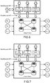
Figure 5 shows a block diagram of a multi-tenant architecture illustrating the concept a Software Defined Multi-Tenant Network; -
Figure 6 shows a block diagram of a multi-tenant architecture of a Software Defined Multi-Tenant Network wherein a home network administrator has no access to a southbound API; -
Figure 7 shows a block diagram of a multi-tenant architecture of a Software Defined Multi-Tenant Network wherein a home network administrator does have access to a southbound API; -
Figures 8 and 9 show an example of implementation of the present principles on smart phone device in reference to the schematic diagram shown inFigure 6 ; -
Figure 10 shows an example of evolution of active flows in a home network from an initial priority status (on the left) to a final priority status (on the right) according to the present principles; - Wherever possible, the same reference numerals will be used throughout the figures to refer to the same or like parts.
- The following description illustrates the principles of the present disclosure. It will thus be appreciated that those skilled in the art will be able to devise various arrangements that, although not explicitly described or shown herein, embody the principles of the disclosure and are included within its scope.
- All examples and conditional language recited herein are intended for educational purposes to aid the reader in understanding the principles of the disclosure, and are to be construed as being without limitation to such specifically recited examples and conditions.
- Moreover, all statements herein reciting principles, aspects, and embodiments of the disclosure, as well as specific examples thereof, are intended to encompass both structural and functional equivalents thereof. Additionally, it is intended that such equivalents include both currently known equivalents as well as equivalents developed in the future, i.e., any elements developed that perform the same function, regardless of structure.
- Thus, for example, it will be appreciated by those skilled in the art that the block diagrams presented herein represent conceptual views of illustrative circuitry embodying the principles of the disclosure. Similarly, it will be appreciated that any flow charts, flow diagrams, state transition diagrams, pseudocode, and the like represent various processes that may be substantially represented in computer readable media and so executed by a computer or processor, whether or not such computer or processor is explicitly shown.
- The functions of the various elements shown in the figures may be provided with dedicated hardware as well as hardware capable of executing software in association with appropriate software. When provided by a processor, the functions may be provided by a single dedicated processor, by a single shared processor, or by a plurality of individual processors, some of which may be shared. Moreover, explicit use of the term "processor" or "controller" should not be construed to refer exclusively to hardware capable of executing software, and may implicitly include, without limitation, digital signal processor (DSP) hardware, read only memory (ROM) for storing software, random access memory (RAM), and nonvolatile storage.
- In the claims hereof, any element expressed as a means and/or module for performing a specified function is intended to encompass any way of performing that function including, for example, a) a combination of circuit elements that performs that function or b) software in any form, including, therefore, firmware, microcode or the like, combined with appropriate circuitry for executing that software to perform the function. It is thus regarded that any means that can provide those functionalities are equivalent to those shown herein.
- In addition, it is to be understood that the figures and descriptions of the present disclosure have been simplified to illustrate elements that are relevant for a clear understanding of the present disclosure, while eliminating, for purposes of clarity, many other elements found in typical digital multimedia content delivery methods, devices and systems. However, because such elements are well known in the art, a detailed discussion of such elements is not provided herein. The disclosure herein is directed to all such variations and modifications known to those skilled in the art.
-
Figure 1 is a schematic diagram of anexemplary network infrastructure 1 wherein the present principles can be implemented. In particular, thenetwork infrastructure 1 can comprise a network element 100 (such as a gateway or a bridge), one ormore devices 10 and one ormore servers 40 delivering one or more services Si, as further shown inFigure 4 . The devices 10 (such as, a portable media device, a mobile phone, a tablet, a Set Top Box, a laptop, a TV set, etc.) are, for instance, in communication with thegateway 100 through a local area network LAN 20 (e.g., via cable or wireless technologies such WiFi). Thegateway 100 can further be in communication with theremote servers 40 via a wide area network WAN 30 (such as Internet) (e.g.; via cable, optic fiber, xDSL, satellite, LTE, 3G/4G/5G technologies, etc.). It should be understood that further apparatuses (not shown) can be arranged betweendevices 10 andgateway 100 and betweengateway 100 andremote servers 40. - As shown in
Figure 2 depicting one non limitative example of a hardware configuration compliant with the present principles, the gateway 100 (which can be any type of broadband gateway such as cable, xDSL, fiber or wireless) comprises: - one or more communication interfaces 110 (wired and/or wireless, as for example Wi-Fi, Ethernet, etc.) allowing one or several connections with
LAN 20 and the WAN 30). Communication interfaces 110 can further comprise user input and/or output elements (e.g., a touch panel, a display screen, a keyboard, a remote control, etc.); - a
communication module 120 comprising the protocol stacks to communicate through the communication interfaces; - a
memory 130 which can represent both a volatile memory such as RAM, and a non-transitory memory such as a ROM, a hard drive or a flash memory, for processing and storing different files and information as necessary, including computer program products and software; - a Central Processing Unit 140 (CPU) comprising one or more processors for executing the applications and/or programs stored in the gateway;
- an
internal bus 150 to connect the various modules and processing means, routing and bridging means and all means well known to the skilled in the art (not shown) for performing the generic gateway functionalities. - The gateway can further comprise a bandwidth manager configured to determine a number of flows between the services Si delivered by the
servers 40 and the devices 10 Dj, from the implementation of the method shown inFigure 3 compliant with the present principles. It should be understood that, in a variant compliant with the present principles, the bandwidth manager can be a standalone network element or can be arranged in another network element (for instance located in the WAN 30) distinct from the gateway. - In particular, as shown in
Figure 3 , themethod 300 can comprise: - obtaining (at step 301), for couples (Si, Dj) defined by a service Si of the set of services and a device Dj of the set of devices, a bandwidth for each flow between the service and the device of said couples;
- obtaining (at step 302) a priority for the flows to be delivered between the services and the devices of said couples;
- solving (at step 303) a 0-1 Knapsack problem by applying the obtained bandwidths and priorities and by considering the available downlink bandwidth of said communication network, to identify one or more allowable flows to be delivered between services of the set of services and devices of the set of devices. The 0-1 Knapsack problem can be formulated as follows:
- Maximize:

- subject to:

- Maximize:
- allowing (at step 304) the identified one or more allowable flows to be delivered to the corresponding devices of said
communication network 20. - Several algorithms are already known to solve the 0-1 Knapsack problem based on greedy, branch-and-bound, dynamic programming, or genetic approached as described, for instance, in the document "Different approaches to solve the 0/1 knapsack problem" from M.Hristakeva and D.Shrestha, in Proc. of 38th Midwest Instruction and Computing Symposium, Apr 2005, incorporated herein by reference.
- In particular, the Dynamic Programming solution to the 0-1 Knapsack problem can be defined as follows:
- {w1, w2 , ..., wn, W} is a set of strictly positive integers,
- for each w ≤ W, let m [i, w] be the maximum value that can be attained, with weight less than or equal to w, using items up to i. m[i,w] can be defined recursively as follows:


- An example of pseudo code for the Dynamic Programming solution to the 0-1 Knapsack Problem is shown herein after:

- Thus, in an embodiment compliant with the present principles, the
bandwidth manager 160, running on thegateway 100, can be configured to activate the maximum number of downlink flows, taking into account the set of flow priorities (for instance given by a user), knowing that the sum of the bandwidths of the activated downlink flows needs to be lower than the available downlink bandwidth B associated with thecommunication network 20. - According to the present principles, the one or more steps of the
method 300 can be performed periodically (such as every 30 seconds) or based on a network event, such as: - a change in the allowed flows (so called active flows). A change in the active flows can happen either because an active flow is finished or because a user in the
LAN 20 requests to start an instance of an available service; - a change in the available downlink bandwidth associated with the
communication network 20; - a change in one or more priorities of the allowable flows by a user input;
- etc.
- It should also be noted that the periodicity of the allocation can, for instance, depend, among other factors, on the processing resources available at the
gateway 100. - In the following, it is considered that:
- S = {S0 ... Sn-1} is a set of n services available in the
LAN 20, at a given time t, - D = {D0 ... Dm-1} is a set of m devices available in the
LAN 20, at a given time t, - bij is the bandwidth required for a downlink flow between a service Si and a device Dj,
- the number of possible flows between the set of services S and the set of devices D, at time t, is n x m,
- pij is the priority of the flow between a service Si and a device Dj which can for instance be assigned by a user having a gateway management role or by an operator,
- xij is a logical variable that is set to 1 when a flow between a service Si and a device Dj is active and is set to 0 otherwise.
- As above mentioned, the goal of the
bandwidth manager 160 of thegateway 100 can be to activate the maximum number of downlink flows, taking into account the set of flow priorities (e.g. given by the user) and knowing that the sum of the bandwidths of the active flows needs to be lower than the available downlink bandwidth B. To that end, thebandwidth manager 160 needs to solve an optimization problem that can be mathematically defined as follows: - Maximize:

- subject to:

- This bandwidth management optimization problem can be considered as the 0-1 Knapsack optimization problem as above described, so that a solution to the 0-1 Knapsack problem can provide a solution to said bandwidth management optimization problem.
-
Figure 4 graphically illustrates the mapping of the bandwidth management problem into the 0-1 Knapsack problem. For sake of clarity, only some possible flows between a service Si and a device Dj are shown. - To determine pij, it can further be considered that:
- PS= {ps0 ... psn-1} is a set of n priorities assigned to the n services, wherein psi ∈ {0,1,...,100} for example. Naturally, psi can belong to another range of values,
- PD = {pd0 ... pdm-1} is a set of m priorities assigned to the m devices, wherein pdj ∈ {0,1,..., 100} in a numerical example. Naturally, pdj can belong to another range of numerical values.
- According to the present principles, a priority pij for a flow between a service Si and a device Dj of a couple (Si, Dj) is defined by the following equation:

- psi is the priority associated with the service Si,
- pdj is the priority associated with the device Dj.
- In a variant compliant with the present principles, a priority pij can be defined by the following equation:

- psi is the priority associated with the service Si,
- pdj is the priority associated with the device Dj,
- C1 and C2 are two constants defined by 0 ≤ C1,C2 ≤ 1 and C1+C2 ≤ 1.
- Besides, to determine psi, it can be further assigned to each service Si of a set of n services, a vector V containing a set of K priorities assigned to a set of K features of said service Si such that:

- As an illustrative but non limitative example, the set of features of the service to consider can be:
- the type of service (e.g., IPTV, VOD, OTT, WEB, etc.),
- the type of stream (e.g., progressive, HAS, backup, etc.),
- the dayparting of the service (e.g.; morning, afternoon, early evening, late evening, etc.),
- the user of the service (e.g. Dad, Mom, Son, Guest, etc.),
- etc.
- The priority psi for the service Si can be obtained from the following equation:

- K is a number of features associated with the service Si
- vsik is a priority associated with the service Si for a feature k amongst the K features of the service Si.
- The set of n priorities psj, corresponding to the n services, can be aggregated into the vector Ps of dimension n.
- In the following numerical example showing the computation of priorities psi compliant with the present principles, it is considered that:
- the available services at the
LAN 20 depend only on two features, such as the type of service (feature f0) and the user of the service (feature f1), - the set of priorities vsi0 assigned to the feature f0 (i.e. the type of service) is IPTV = 100, VOD = 100, OTT = 50, WEB = 10;
- the set of priorities vsi1 assigned to the feature f1 (i.e. the user of the service) is Dad = 100, Mom = 100, Son = 50, Guest = 10.
- In a first moment t1, it is considered that Dad is watching Netflix (VOD service So), whereas Son is playing a game in the TF1 WEB site (WEB service S1). In this case, the vectors of service priorities Vsi are:


- In a second moment t2, it is considered that Dad and Mom are watching together Orange IPTV (IPTV service So), whereas Son is receiving a stream from the TF1 WEB site (OTT service S1). In this case, the vectors of service priorities Vsi are:


- Besides, to determine pdj, it can be further assigned to, each device Dj of the set of m devices, a vector V containing a set of K priorities assigned to a set of K attributes of said device Dj such that:

- As an illustrative but non limitative example, the set of features of the devices to consider can be:
- the type of device (e.g., TV, PC, Tablet, Smartphone, etc.),
- the user of the device (e.g., Dad, Mom, Child, Guest, etc.),
- the location of the device (e.g., living room, bedroom, kitchen, games room, etc.),
- the dayparting (e.g., morning, afternoon, early evening, late evening, etc.),
- etc.
- The priority pdj for the device Dj can be obtained from the following equation:

- K is a number of attributes associated with the device Dj
- vdjk is a priority associated with the device Dj for an attribute k amongst the K attributes of the device Dj.
- The set of m priorities pdj, corresponding to the m services, can be aggregated into a vector Pd of dimension m.
- In the following numerical example showing the computation of priorities pdj compliant with the present principles, it is considered that:
- the available devices in
LAN 20 have only three distinctive attributes, such as the type of device (attribute a0), the user of the device (attribute a1), and the location of the device (attribute a2), - the set of priorities vdj0 assigned to the attribute a0 (i.e. the type of device) is TV = 100, PC = 50, Tablet = 80, Game Console = 100,
- the set of priorities vdj1 assigned to the attribute a1 (i.e. the user of the device) is Dad = 100, Mom = 100, Son = 50, Guest = 50,
- the set of priorities vdj2 assigned to the attribute a2 (i.e. the location of the device) is Office = 80, Living room = 100, Kitchen = 50, Bedroom = 80.
- In a first moment t1, it is considered that Dad is in the Office using his PC (device D0), Mom is in the Kitchen using her Tablet (device D1), and Son is in the living room playing with the Game Console (device D2).). In this case, the vectors of device priorities Vdj are:


- In a second moment t2, it is considered that Dad is in the Office using his PC (device D0), Mom is in the Living room using her Tablet (device D1), and Son is in his bedroom watching TV (device D2). In this case, the vectors of device priorities Vdj are:


- Besides, to determine the bandwidth bij required for a downlink flow between a service Si and a device Dj, it can be considered that:
- bsi = [bs.mini, bs.maxi] is the range of bitrates available from the service Si. Indeed, some services Si might be available with different levels of QoS (Quality of Service). YouTube is an example where the service is available for Standard Definition and High Definition each definition requiring less or more bit-rate. HTTP Adaptive Streaming (such as HTTP Live Streaming or HLS from APPLE) is another example where the service is available for a range of QoS levels, and hence a range of bit-rates (multi bit-rate service),
- bdj = [bd.minj, bd.maxj] is the range of bitrates supported by the device Dj. Some characteristics of the device Dj can make useless to receive a service with a bit-rate higher than a certain value. For example, the screen resolution of a smart-phone can limit the maximum bit-rate that is suitable for a video streaming service. In addition, the CPU processing power of a low cost smart-phone can for example limit the maximum packet throughput,
- [Max (bs.mini, bd.minj); Min (bs.maxi, bd.maxj)] is the range of allowable bit-rates for a flow stream between the service Si and the device Dj.
- Thus, the bandwidth bij required for a downlink flow between a service Si and a device Dj can be obtained from the range of allowable bit-rates [Max (bs.mini, bd.minj); Min (bs.maxi, bd.maxj)] based, for instance, on a bandwidth manager policy associated with the
LAN 20. Some examples of the bandwidth manager policy can be: - priority to fairness by, for instance, selecting the maximum number of flows by allocating the bandwidth Max (bs.mini, bd.minj) to each flow,
- priority to quality by, for instance, selecting the maximum number of flows by allocating the bandwidth Min (bs.maxi, bd.maxj) to each selected flow,
- priority to user preferences by, for instance, pick something in between the two previous policies (fairness, quality) tailored to user preferences. A user acting as a gateway administrator can for example select one or more preferences and/or bandwidth manager policies. For instance, a check box can be presented to such a user (through for instance a bandwidth management application) so that the user can choose one policy from the set of profile policies implemented in the system.
- For the implementation of the present principles, the concept of Software Defined Multi-Tenant Network, as illustrated in
Figure 5 , can be used. The Multi-Tenancy principle (also known as Slicing) relies on sharing the network control among several administrators, among them an end user with administrator rights at home (so called HNA or Home Network Administrator), an ISP (Internet Service Provider), and other service providers. - In addition, Software Defined Networking (SDN) is a paradigm that separates the control and data planes into two specific entities to bring flexibility and programmability to the networks and to ease the management of multi-tenant networks. In a SDN environment, the network applications communicate and send their network service requests to the controller via Northbound Application Programming Interfaces (NBIs). Accordingly, the controller (HNA, ISP, Tenant 1) translates the requests into low-level forwarding rules and installs them in the data plane network apparatuses via Southbound Application Programming Interfaces (SBIs).
- In an example compliant with the present principles shown in
Figure 6 , thelocal network 20 is considered as a multi-tenant network, wherein at least two tenants are present: the Home Network Administrator (HNA) and the Internet Service Provider (ISP). Additional tenants might be Over the Top (OTT) and Internet of Things (IoT) service providers (twoadditional tenants Tenant 1 andTenant 2 are shown inFigure 6 ). The tenants are allowed to have higher and differentiated levels of control over the slices of the available resources. In the example, the southbound multi-tenancy architecture is implemented, wherein each tenant - except the HNA-owns his own controller and shares the common forwarding elements of thelocal network 20. - Since the HNA has no access to the Southbound API, the HNA communicates his preferences to the other controllers, e.g., the ISP controller, through a dedicated interface. For example, the HNA can use an application on his smart phone (or tablet, computer, etc.) to modify and configure his profile and preferences. In other words, the HNA tenant has a consultative role about the control of the slices assigned to each service the user has subscribed to but he does not have a direct control of the slices, the control of the slices is the service providers' responsibility.
-
Figure 8 depicts an illustrative, but non limitative, example of implementation of the present principles on smart phone device in reference to the schematic diagram shown inFigure 6 . In this example, ahome network 20 is considered which comprises agateway 100 and four devices 10 (such as a smart TV, a smart phone, a portable PC, a desktop PC). Four users (Dad, Mom, Son and Daughter) can use the four devices. - In said example, a smart-
phone application 501 can be implemented on a smart-phone 500 (belonging to the home network) to display to the HNA an orderedlist 502 oficons 510 arranged in column, eachicon 510 representing a distinct service as shown inFigure 8 . The icon (i.e. the corresponding service) at the top of the column has the highest priority and the icon (i.e. the corresponding service) at the bottom of the column has the lowest priority. The HNA has the possibility to modify the proposed order for the services by moving theicons 510 in the column, for instance by interaction with the touch screen of the smart-phone 500, as shown inFigure 8 . Two services having the same priority can be arranged on a same row. - The smart-phone application can then convert the displayed ordered list of service icons into an Event-Condition-Action (ECA) policy rule, as follows:
- Event: Initialize default service priorities
- Condition: None
- Action: Netflix > Youtube > Update of Windows OS > Facebook > Update of Ubuntu OS
- In the example shown in
Figure 8 , "Netflix > Youtube > Update of Windows OS" means that Netflix has higher priority than Youtube and Update of Windows OS, and Youtube has higher priority than Update of Windows OS. - This ECA policy rule can be stored into a policy file that can be read by the ISP controller which needs to translate the ECA policy rule into a set of numerical priorities as previously described. The ISP controller can be embedded within the
gateway 100. - Thus, when S0 = Netflix, S1 = Youtube, S2 = Update of Windows OS, S3 = Facebook, and S4 = Update of Ubuntu OS, the set of services S is:

- For simplicity, in this example, it is considered that the priority of each service Si depends only on a single feature of the service. Therefore, the vector Vsi can be Vsi = [vsi0] and psi = vsi0. With an evenly distributed set of priorities Ps to the six available services, the set Ps of priorities assigned to the six available services is:

- As shown in
Figure 9 , the smart-phone application 501 can further to display to the HNA an orderedlist 503 oficons 510 arranged in column, eachicon 510 representing adistinct device 10 of the considered home network. The icon (i.e. the corresponding device) at the top of the column has the highest priority and the icon (i.e. the corresponding device) at the bottom of the column has the lowest priority. The HNA has also the ability to change the proposed order for the devices by moving theicons 510 in the column. - As for the services, the smart-phone application can convert the displayed ordered list of device icons into an ECA policy rule, as follows:
- Event: Initialize default device priorities
- Condition: None
- Action: Smart TV > Smart Phone > Portable PC > Desktop PC.
- Thus, when D0 = Smart TV, D1 = Smart Phone, D2 = Portable PC, and D3 = Desktop PC, the set D of available devices is:

- For simplicity, in this example, it is considered that the priority of each device Di depends only on a single feature of the device. Therefore, the vector Vdj is Vdj = [vdj0] and pdj = vdj0. With an evenly distributed set of priorities Pd to the four available devices, the set Pd of priorities assigned to the four available devices is:

- The right side of
Figure 9 shows the update of the ordered list of priorities of the set of devices after, for instance, one HNA's interaction (e.g. thanks to the touch screen by sliding icons to a desired position in the list). -
Figure 10 shows an evolution of active flows from an initial priority status (on the left side) to a final priority status (on the right side) with reference to the conditions ofFigure 8 . - In the initial priority status of the active flows, only Son and Daughter are at Home. Daughter is watching YouTube on the Smart TV, and at the same time browsing Facebook on her smart phone, and in the meantime, the Son's Desktop PC is receiving an Update of Windows OS.
- Dad arrives at Home and wishes to watch a film from Netflix on the Smart TV. Daughter gives way the Smart TV to Dad and switches the YouTube stream to her smart phone.
- In the final priority status of the active flows, Dad watches a Netflix film on the SmartTV, Daughter is watching YouTube stream on her smartphone and at the same time browsing Facebook on her smart phone, and the Son's Desktop PC is receiving an Update of Windows OS.
- The sequence of events of
Figure 10 can be translated by the HNA controller (which can be embedded within the gateway 100) into an ECA policy rule as follows to be handled by the ISP controller: - Event: Add a new service-to-device flow to the active flows list
- Condition: The total bandwidth required by the new list of active flows should not exceed the available downlink bandwidth B
- Action: Activate the service-to-device flows having the highest priority, i.e. by solving the bandwidth management optimization problem previously described.
- In
Figure 8 to 10 , it is assumed that the total bandwidth consumed by all the new active services is smaller than the available downlink bandwidth B. When this is not the case, thebandwidth manager 160 can drop (or not choose) the flow with the lowest priority (i.e. the Windows OS update in the example). - In another embodiment of the present principles, the HNA can have the possibility to modify on the fly the flow priorities of the solution produced by the bandwidth manager solving the bandwidth management optimization problem. This would mean that the sets of service and device priorities (Ps, Pd), used as input for solving the bandwidth management optimization problem, do not represent the user wishes in the present context.
- In this embodiment, several solutions can be implemented:
- 1st solution: follow the user's wishes and ignore the bandwidth management optimization problem (i.e. the 0-1 Knapsack problem) until an active flow drops. When a new flow arrives, restart and solve the bandwidth management optimization problem with the saved service and device priorities (Ps, Pd);
- 2nd solution: follow the user's wishes and update the policy file (Ps, Pd) as follows:
- ▪ select the top flows selected by the user whose sum of the required bit-rates is less than B,
- ▪ assign to this new set of flows the set of priorities pij of the top flows of the previous set of active flows,
- ▪ reassign the set of psi priorities according to the new order. The reassignment of the psi priorities can incorporate additional features to the vector Vsi such as the location of the device at home, the day and time of the emission, the identification of the user behind a device, etc.,
- ▪ determine the set of pdj priorities from:

- ▪ update the policy file (Ps, Pd) accordingly.
- Besides, in a variant compliant with the present principles, the HNA can be allowed to have direct access to the Southbound API as shown in
Figure 7 . When the end user subscribes to a service, the HNA is provided by the service provider with a standard profile that the HNA can modify. The standard profile corresponds to an average user and it contains the priority settings previously described. Before granting an access to the Southbound API to the HNA controller, the ISP controller needs to verify that the HNA settings are valid. Therefore, interaction between the HNA and ISP controllers can be required. - In a further variant compliant with the present principles, the HNA can get access to the Southbound API through the ISP controller. The difference with the previous variant is that the HNA has access only to the settings of the services provided by the ISP and has no direct access to the settings of the services provided by the other tenants.
- Thus, thanks to the present principles, the
bandwidth management method 300 can allow to activate the maximum number of flows, taking into account the set of flow priorities (for instance given by a user or by an operator), knowing that the sum of the bandwidths of the active flows needs to be lower than the available downlink bandwidth B. - In the Figures, it is to be appreciated that the illustrated blocks or modules can correspond to functional modules, which may or may not correspond to distinguishable physical units. For example, a plurality of such modules may be associated in a unique component or circuit, or correspond to software functionalities. Moreover, a module may potentially be composed of separate physical entities or software functionalities.
- References disclosed in the description, the claims and the drawings might be provided independently or in any appropriate combination. Features may be, where appropriate, implemented in hardware, software, or a combination of the two.
- Reference herein to "one embodiment" or "an embodiment" means that a particular feature, structure, or characteristic described in connection with the embodiment can be included in at least one implementation of the method and device described. The appearances of the phrase "in one embodiment" in various places in the specification are not necessarily all referring to the same embodiment, nor are separate or alternative embodiments necessarily mutually exclusive of other embodiments.
- Reference numerals appearing in the claims are by way of illustration only and shall have no limiting effect on the scope of the claims.
- Although certain embodiments only of the disclosure have been described herein, it will be understood by any person skilled in the art that other modifications, variations, and possibilities of the disclosure are possible. Such modifications, variations and possibilities are therefore to be considered as falling within the spirit and scope of the disclosure and hence forming part of the disclosure as herein described and/or exemplified.
- The flowchart and/or block diagrams in the Figures illustrate the configuration, operation and functionality of possible implementations of systems, methods and computer program products according to various embodiments of the present disclosure. In this regard, each block in the flowchart or block diagrams may represent a module, segment, or portion of code, which comprises one or more executable instructions for implementing the specified logical function(s). It should also be noted that, in some alternative implementations, the functions noted in the block may occur out of the order noted in the figures. For example, two blocks shown in succession may, in fact, be executed substantially concurrently, or the blocks may sometimes be executed in the reverse order, or blocks may be executed in an alternative order, depending upon the functionality involved. It will also be noted that each block of the block diagrams and/or flowchart illustration, and combinations of the blocks in the block diagrams and/or flowchart illustration, can be implemented by special purpose hardware-based systems that perform the specified functions or acts, or combinations of special purpose hardware and computer instructions. While not explicitly described, the present embodiments may be employed in any combination or sub-combination.
Claims (15)
- Method to be implemented at a network element adapted to be connected to a communication network (20) comprising a set of devices (D0, D1, Dj), said devices being configured to receive one set of available services (So, S1, Si), wherein said method comprises:- obtaining (301), for couples defined by a service of the set of services (So, S1, Si) and a device of the set of devices (D0, D1, Dj), a bandwidth (b00, b11, bij) for each flow between the service and the device of said couples;- obtaining (302) a priority (p00, p11, pij) for the flows to be delivered between the services and the devices of said couples;- solving (303) a 0-1 Knapsack problem by applying the obtained bandwidths (b00, b11, bij) and priorities (p00, p11, pij) and by considering an available downlink bandwidth associated with said communication network (20), to identify one or more allowable flows to be delivered between services of the set of services and devices of the set of devices;- allowing (304) the identified one or more allowable flows to be delivered to the corresponding devices of said communication network (20).
- Method according to claim 1, wherein a bandwidth (b00, b11, bij) for a flow associated with one of said couples is obtained from a range of allowable bit-rates for said flow between the service and the device of said couple.
- Method according to claim 2, wherein the range of allowable bit-rates for said flow between the service and the device of said couple is defined by the range [Max (bs.mini, bd.minj); Min (bs.maxi, bd.maxj)], wherein:- [bs.mini, bs.maxi] is the range of bitrates available from the service Si of said couple (Si, Dj)- [bd.minj, bd.maxj] is the range of bitrates supported by the device Dj of said couple (Si, Dj).
- Method according to claim 3, wherein the bandwidth (b00, b11, bij) for a flow associated with one of said couples, obtained from the range [Max (bs.mini, bd.minj); Min (bs.maxi, bd.maxj)], depends on a bandwidth manager policy associated with said communication network (20).
- Method according to claim 4, wherein said bandwidth manager policy associated with said communication network (20) belongs to the following group of policies comprising:- priority to fairness;- priority to quality;- priority to user preferences.
- Method according to claims 1 to 5, wherein allowing the identified one or more allowable flows is performed periodically.
- Method according to claims 1 to 6, wherein allowing the identified one or more allowable flows is performed based on a network event.
- Method according to claims 1 to 8, wherein a priority (p00, p11, pij) for a flow between the service (Si) and the device (Dj) of said couples is defined by:
 - psi is the priority associated with the service Si- pdj is the priority associated with the device Dj- C1 and C2 are two constants defined by 0 ≤ C1,C2 ≤ 1 and C1+C2 ≤ 1.
 - Network element to be connected to a communication network (20) comprising a set of devices (D0, D1, Dj), said devices being configured to receive one set of available services (S0, S1, Si),
wherein said network element (100) comprises at least one memory (130) and one or more processors (140) configured to:- obtain, for couples defined by a service of the set of services (S0, S1, Si) and a device of the set of devices (D0, D1, Dj), a bandwidth (boo, b11, bij) for each flow between the service and the device of said couples;- obtain a priority (p00, p11, pij) for the flows to be delivered between the services and the devices of said couples;- solve a 0-1 Knapsack problem by applying the obtained bandwidths (b00, b11, bij) for and priorities (p00, p11, pij) and by considering an available downlink bandwidth associated with said communication network (20), to identify one or more allowable flows to be delivered between services of the set of services (S0, S1, Si) and devices of the set of devices (D0, D1, Dj);- allow the identified one or more allowable flows to be delivered to the corresponding devices (D0, D1, Dj) of said communication network (20). - Network element adapted to be connected to a communication network (20) comprising a set of devices (D0, D1, Dj), said devices being configured to receive one set of available services (S0, S1, Si),
wherein the network element is a bandwidth manager (160) configured to:- obtain, for couples defined by a service of the set of services (S0, S1, Si) and a device of the set of devices (D0, D1, Dj), a bandwidth (b00, b11, bij) for each flow between the service and the device of said couples;- obtain a priority (p00, p11, pij) for the flows to be delivered between the services and the devices of said couples;- solve a 0-1 Knapsack problem by applying the obtained bandwidths (b00, b11, bij) and priorities (p00, p11, pij) and by considering an available downlink bandwidth associated with said communication network (20), to identify one or more allowable flows to be delivered between services of the set of services (S0, S1, Si) and devices of the set of devices (D0, D1, Dj);- allow the identified one or more allowable flows to be delivered to the corresponding devices of said communication network (20). - Network element according to claim 10, wherein a bandwidth for a flow associated with one of said couples is obtained from a range of allowable bit-rates for said flow between the service and the device of said couple.
- Network element according to claim 11, wherein the range of allowable bit-rates for said flow between the service and the device of said couple (Si, Dj) is defined by the range [Max (bs.mini, bd.minj); Min (bs.maxi, bd.maxj)], wherein:- [bs.mini, bs.maxi] is the range of bitrates available from the service Si of said couple (Si, Dj)- [bd.minj, bd.maxj] is the range of bitrates supported by the device Dj of said couple (Si, Dj).
- Network element according to claim 12, wherein the bandwidth (b00, b11, bij) for a flow associated with one of said couples, obtained from the range [Max (bs.mini, bd.minj); Min (bs.maxi, bd.maxj)], depends on a bandwidth manager policy associated with said communication network.
- Network element according to claim 13, wherein said bandwidth manager policy associated with said communication network belongs to the following group of policies comprising:- priority to fairness;- priority to quality;- priority to user preferences.
- Network element according to claims 10 to 14, arranged in a gateway (100).
Priority Applications (2)
| Application Number | Priority Date | Filing Date | Title |
|---|---|---|---|
| EP17305376.0A EP3382962A1 (en) | 2017-03-30 | 2017-03-30 | Method for managing active flows in a communication network by a network element, and corresponding network element |
| US15/938,309 US20180287888A1 (en) | 2017-03-30 | 2018-03-28 | Method for managing active flows in a communication network by a network element, and corresponding network element |
Applications Claiming Priority (1)
| Application Number | Priority Date | Filing Date | Title |
|---|---|---|---|
| EP17305376.0A EP3382962A1 (en) | 2017-03-30 | 2017-03-30 | Method for managing active flows in a communication network by a network element, and corresponding network element |
Publications (1)
| Publication Number | Publication Date |
|---|---|
| EP3382962A1 true EP3382962A1 (en) | 2018-10-03 |
Family
ID=58548646
Family Applications (1)
| Application Number | Title | Priority Date | Filing Date |
|---|---|---|---|
| EP17305376.0A Withdrawn EP3382962A1 (en) | 2017-03-30 | 2017-03-30 | Method for managing active flows in a communication network by a network element, and corresponding network element |
Country Status (2)
| Country | Link |
|---|---|
| US (1) | US20180287888A1 (en) |
| EP (1) | EP3382962A1 (en) |
Citations (3)
| Publication number | Priority date | Publication date | Assignee | Title |
|---|---|---|---|---|
| WO2002087153A2 (en) * | 2001-04-20 | 2002-10-31 | Newmic Foundation | Revenue-optimal admission controller with hard quality of service guarantees for data networks |
| EP2323314A1 (en) * | 2009-11-17 | 2011-05-18 | Thomson Telecom Belgium | Method of accessing services and corresponding apparatus |
| EP2879339A1 (en) * | 2013-11-27 | 2015-06-03 | Thomson Licensing | Method for distributing available bandwidth of a network amongst ongoing traffic sessions run by devices of the network, corresponding device. |
-
2017
- 2017-03-30 EP EP17305376.0A patent/EP3382962A1/en not_active Withdrawn
-
2018
- 2018-03-28 US US15/938,309 patent/US20180287888A1/en not_active Abandoned
Patent Citations (3)
| Publication number | Priority date | Publication date | Assignee | Title |
|---|---|---|---|---|
| WO2002087153A2 (en) * | 2001-04-20 | 2002-10-31 | Newmic Foundation | Revenue-optimal admission controller with hard quality of service guarantees for data networks |
| EP2323314A1 (en) * | 2009-11-17 | 2011-05-18 | Thomson Telecom Belgium | Method of accessing services and corresponding apparatus |
| EP2879339A1 (en) * | 2013-11-27 | 2015-06-03 | Thomson Licensing | Method for distributing available bandwidth of a network amongst ongoing traffic sessions run by devices of the network, corresponding device. |
Non-Patent Citations (1)
| Title |
|---|
| M.HRISTAKEVA; D.SHRESTHA: "Different approaches to solve the 0/1 knapsack problem", PROC. OF 38TH MIDWEST INSTRUCTION AND COMPUTING SYMPOSIUM, April 2005 (2005-04-01) |
Also Published As
| Publication number | Publication date |
|---|---|
| US20180287888A1 (en) | 2018-10-04 |
Similar Documents
| Publication | Publication Date | Title |
|---|---|---|
| US11902108B2 (en) | Dynamic adaptive network | |
| EP3319322A1 (en) | Bandwidth adjustment method and related device | |
| JP6442507B2 (en) | How to allocate available network bandwidth during ongoing traffic sessions performed by devices on the network, corresponding devices | |
| KR20120053049A (en) | Method and apparatus for managing allocation of resources in a network | |
| US11722430B2 (en) | Technologies for context-aware dynamic bandwidth allocation | |
| CN111769970B (en) | Network slice wireless resource demand management method | |
| WO2018145376A1 (en) | Method and system for controlling wireless devices to share bandwidth | |
| KR102535029B1 (en) | Systems and methods for optimizing simulcast streams in group video calls | |
| WO2015096680A1 (en) | Node distribution method and control center | |
| US20250080619A1 (en) | Operations control of network services | |
| KR101613513B1 (en) | Virtual machine placing method and system for guarantee of network bandwidth | |
| CN114828235A (en) | Bandwidth allocation method, bandwidth allocation device and computer-readable storage medium | |
| CN113347113B (en) | Flow control method, device, equipment and computer storage medium | |
| WO2017185908A1 (en) | Resource scheduling method and device, and data storage medium | |
| EP3220677B1 (en) | Network based control of wireless communications | |
| CN113923206B (en) | Data transmission method, device and system | |
| CN121441753A (en) | Systems and methods for latency optimization of cloud applications | |
| US20180287888A1 (en) | Method for managing active flows in a communication network by a network element, and corresponding network element | |
| CN104901903A (en) | Multi-domain resource processing method and system for software defined network | |
| US11134411B2 (en) | Dynamic uplink resource unit scheduling for UL-OFDMA in 802.11ax networks | |
| Wamser et al. | Modelling and performance analysis of application‐aware resource management | |
| de Oliveira et al. | Slicing Wi‐Fi links based on QoE video streaming fairness | |
| Krithika et al. | A Comprehensive View of State-of-Art of 5G Network Slicing | |
| WO2015089821A1 (en) | Policy rules for network resource | |
| JP2017156791A (en) | User accommodation management system and method |
Legal Events
| Date | Code | Title | Description |
|---|---|---|---|
| PUAI | Public reference made under article 153(3) epc to a published international application that has entered the european phase |
Free format text: ORIGINAL CODE: 0009012 |
|
| AK | Designated contracting states |
Kind code of ref document: A1 Designated state(s): AL AT BE BG CH CY CZ DE DK EE ES FI FR GB GR HR HU IE IS IT LI LT LU LV MC MK MT NL NO PL PT RO RS SE SI SK SM TR |
|
| AX | Request for extension of the european patent |
Extension state: BA ME |
|
| STAA | Information on the status of an ep patent application or granted ep patent |
Free format text: STATUS: THE APPLICATION IS DEEMED TO BE WITHDRAWN |
|
| 18D | Application deemed to be withdrawn |
Effective date: 20190404 |