EP3382954A1 - Traceroute for multi-path routing - Google Patents
Traceroute for multi-path routing Download PDFInfo
- Publication number
- EP3382954A1 EP3382954A1 EP18152156.8A EP18152156A EP3382954A1 EP 3382954 A1 EP3382954 A1 EP 3382954A1 EP 18152156 A EP18152156 A EP 18152156A EP 3382954 A1 EP3382954 A1 EP 3382954A1
- Authority
- EP
- European Patent Office
- Prior art keywords
- network device
- router
- traceroute
- paths
- packet
- Prior art date
- Legal status (The legal status is an assumption and is not a legal conclusion. Google has not performed a legal analysis and makes no representation as to the accuracy of the status listed.)
- Granted
Links
Images



Classifications
-
- H—ELECTRICITY
- H04—ELECTRIC COMMUNICATION TECHNIQUE
- H04L—TRANSMISSION OF DIGITAL INFORMATION, e.g. TELEGRAPHIC COMMUNICATION
- H04L45/00—Routing or path finding of packets in data switching networks
- H04L45/24—Multipath
-
- H—ELECTRICITY
- H04—ELECTRIC COMMUNICATION TECHNIQUE
- H04L—TRANSMISSION OF DIGITAL INFORMATION, e.g. TELEGRAPHIC COMMUNICATION
- H04L43/00—Arrangements for monitoring or testing data switching networks
- H04L43/10—Active monitoring, e.g. heartbeat, ping or trace-route
-
- H—ELECTRICITY
- H04—ELECTRIC COMMUNICATION TECHNIQUE
- H04L—TRANSMISSION OF DIGITAL INFORMATION, e.g. TELEGRAPHIC COMMUNICATION
- H04L45/00—Routing or path finding of packets in data switching networks
- H04L45/20—Hop count for routing purposes, e.g. TTL
-
- H—ELECTRICITY
- H04—ELECTRIC COMMUNICATION TECHNIQUE
- H04L—TRANSMISSION OF DIGITAL INFORMATION, e.g. TELEGRAPHIC COMMUNICATION
- H04L45/00—Routing or path finding of packets in data switching networks
- H04L45/26—Route discovery packet
-
- H—ELECTRICITY
- H04—ELECTRIC COMMUNICATION TECHNIQUE
- H04L—TRANSMISSION OF DIGITAL INFORMATION, e.g. TELEGRAPHIC COMMUNICATION
- H04L45/00—Routing or path finding of packets in data switching networks
- H04L45/74—Address processing for routing
-
- H—ELECTRICITY
- H04—ELECTRIC COMMUNICATION TECHNIQUE
- H04L—TRANSMISSION OF DIGITAL INFORMATION, e.g. TELEGRAPHIC COMMUNICATION
- H04L47/00—Traffic control in data switching networks
- H04L47/10—Flow control; Congestion control
- H04L47/28—Flow control; Congestion control in relation to timing considerations
- H04L47/286—Time to live
-
- H—ELECTRICITY
- H04—ELECTRIC COMMUNICATION TECHNIQUE
- H04L—TRANSMISSION OF DIGITAL INFORMATION, e.g. TELEGRAPHIC COMMUNICATION
- H04L41/00—Arrangements for maintenance, administration or management of data switching networks, e.g. of packet switching networks
- H04L41/12—Discovery or management of network topologies
-
- H—ELECTRICITY
- H04—ELECTRIC COMMUNICATION TECHNIQUE
- H04L—TRANSMISSION OF DIGITAL INFORMATION, e.g. TELEGRAPHIC COMMUNICATION
- H04L41/00—Arrangements for maintenance, administration or management of data switching networks, e.g. of packet switching networks
- H04L41/20—Network management software packages
Definitions
- the present teaching relates to computer networks and, more particularly but not exclusively, to software utilities for determining the status of computer network connections.
- a computer network is a collection of interconnected computing devices that can exchange data and share resources.
- the computing devices communicate data by dividing the data into small blocks called packets, which are individually routed across the network from a source device to a destination device.
- the destination device extracts the data from the packets and assembles the data into its original form.
- routers maintain routing information that describes routes through the network.
- a "route” can generally be defined as a path between two locations on the network.
- the router Upon receiving an incoming packet, the router examines information within the packet to identify the destination for the packet. Based on the destination, the router forwards the packet in accordance with the routing information.
- traceroute allows a source network device to identify a network path from the source network device to a destination network device.
- the traceroute utility determines the network path to a target network device by recording an Internet Control Message Protocol (ICMP) echo request packet's path from the source device to a specified network destination.
- ICMP Internet Control Message Protocol
- the traceroute typically displays how many hops the packet traveled to reach the network destination, identifies each hop along the path by its network address, and shows the round-trip time for reaching each hop.
- this disclosure describes techniques for extending network connectivity software utilities, such as traceroute, to provide complete visibility into a network topology between a source device and a destination device, even when an intermediate network device may be actively utilizing multiple network links when forwarding packets toward the destination.
- a network device in the network path such as an intermediate router, may be configured to actively utilize multiple paths, i.e., links, when forwarding traffic to reach a destination network device.
- the intermediate device may be configured to generally apply equal cost multi-path for forwarding packets on any of a set of active links based on a hashing operation.
- the intermediate network device may utilize respective sessions to track forwarding of a corresponding traceroute packet along each of the active multiple paths. For example, in response to receiving a traceroute packet specifying the network destination, the intermediate network device may configure and output a respective modified traceroute packet on each of the corresponding paths leading from the network device toward the destination.
- the respective modified traceroute packets may each include a respective identifier associated with the corresponding path of the multiple paths. The network device forwards the respective modified traceroute packets along the corresponding paths such that each path may be traced by its respective traceroute packet.
- a subsequent network device along each of the paths receives the modified traceroute packet for a given path and configures a response to include an identifier associated with the corresponding path.
- the network device may associate the response with the particular path along which the modified traceroute packet was forwarded to the network device.
- the source network device updates the results of the traceroute utility to reflect each of the multiple paths within the network and configures a new traceroute packet with an incremented Time-to-Live (TTL) value and sends the traceroute packet towards the destination network device.
- TTL Time-to-Live
- the source network device continues this process until a response is received from the destination network device.
- the traceroute packets and the responses may provide source network device with complete visibility even when a given intermediate device may be actively forwarding packets destined for the destination, even for the same packet flow, along multiple network paths.
- a method may include receiving, by a network device coupled to a plurality of paths for reaching a destination network device and positioned between a source network device and the destination network device, a traceroute packet.
- the method may also include, for each of the plurality of paths, modifying, by the network device, a payload of the traceroute packet to include a respective identifier for a corresponding path of the plurality of paths to construct a respective modified traceroute packet for the corresponding path.
- the method may also include forwarding, by the network device, the respective modified traceroute packets on the corresponding paths.
- a method may include sending, by a source network device, a traceroute packet to an intermediate network device coupled to a plurality of paths for reaching a destination network device, wherein the intermediate network device is positioned between the source network device and the destination network device.
- the method may also include receiving, by the source network device and from the intermediate network device, one or more respective responses, wherein each of the one or more respective responses comprises a payload including a respective identifier for a corresponding path of the plurality of paths.
- a network device may include a plurality of network interfaces, each of the network interfaces coupled to a different one of a plurality of paths for reaching a destination network device, wherein the network device is positioned between a source network device and the destination network device.
- the network device may also include one or more hardware-based processors configured to: receive a traceroute packet destined for the destination device; for each of the plurality of paths, modify a payload of the traceroute packet to include a respective identifier for a corresponding path of the plurality of paths to construct a respective modified traceroute packet for the corresponding path; and forward the respective modified traceroute packets on the corresponding paths.
- a source network device may include one or more hardware-based processors configured to: send a traceroute packet toward a destination network device; and receive one or more respective responses, wherein each of the one or more respective responses comprises a payload including a respective identifier for a corresponding path of a plurality of paths of an intermediate network device, wherein the intermediate network device is positioned between the source network device and the destination network device.
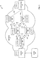
- FIG. 1 is a block diagram illustrating an example network system in which intermediate network devices have been enhanced so as to enable a software utility, such as traceroute, to trace and report on connectivity information from a source destination to a destination device, even when one or more of the intermediate network device utilize multiple, active links when forwarding packets of the utility toward the destination.
- source network device 12 and network device 18A-18E (collectively, “network devices 18" or “routers 18") support use of the extended traceroute that has been extended to facilitate exploration of a network topology of each of the multiple paths when forwarding traffic to reach a destination network device.
- network system 10 includes source network device 12 and destination network device 14 connected across network 8 via intermediate routers, switches, and other network devices, shown for purposes of examples as routers 18.
- Network 8 may comprise a public network such as the Internet, a private network, such as those owned and operated by an enterprise or service provider or a combination of both public and private networks.
- network 8 may be alternatively referred to herein as a Service Provider (SP) network.
- SP Service Provider
- Network 8 may include one or more Wide Area Networks (WANs), Local Area Networks (LANs), Virtual Local Area Networks (VLANs), Virtual Private Networks (VPNs), and/or another type of network.
- WANs Wide Area Networks
- LANs Local Area Networks
- VLANs Virtual Local Area Networks
- VPNs Virtual Private Networks
- network 8 may be an Internet Protocol (IP) network in which routers 18 use IP forwarding for transporting network packets.
- IP Internet Protocol
- network 8 may be a label switching network in which network devices such as routers 18, often referred to as Label Switching Routers or LSRs, use Multi-Protocol Label Switching (MPLS) signaling protocols to establish Label Switched Paths (LSPs) for transporting the network packets received from source devices 12.
- MPLS Multi-Protocol Label Switching
- LSPs Label Switched Paths
- the MPLS data-carrying mechanism of network 8 may be viewed as lying between layer 2 and layer 3 of the Open Systems Interconnection (OSI) model and is often referred to as a layer 2.5 protocol. Reference to layers followed by a numeral may refer to a particular layer of the OSI model.
- OSI Open Systems Interconnection
- network 8 may comprise any number of interconnected networks, either public or private, in which the various networks interconnect to form various virtual networks.
- network 8 may include a variety of other network devices for forwarding network traffic, such as additional routers, switches, or bridges.
- additional routers, switches, or bridges may be included in a single network or within multiple networks.
- routers 18 may reside in a single network or within multiple networks. Although described with respect to routers, aspects of the techniques are applicable to other network devices, such as bridges, switches, gateways, network caches, and network acceleration devices.
- source network device 12 and destination network device 14 may each be a personal computer, a laptop computer, a mobile telephone, a network telephone, a television set-top box, a network device integrated into a vehicle, a video game system, a point-of-sale device, a personal digital assistant, an intermediate network device, a network appliance, a supercomputer, a mainframe computer, or another type of device capable of interfacing with and communicating over network 8.
- Physical links of network 8 may include, for example, Ethernet PHY, Synchronous Optical Networking (SONET)/Synchronous Digital Hierarchy (SDH), Lambda, or other Layer 2 data links that include packet transport capability.
- Logical links of network 8 may include, for example, an Ethernet Virtual LAN, an MPLS LSP, or an MPLS-TE LSP.
- source network device 12 connects to network 8 via access link 15A
- destination network device 14 connects to network 8 via access links 15G and/or 15H
- routers 18 communicate via access links 15B-15F.
- Access links 15 may comprise wired and/or wireless communication links.
- the term "communication link,” as used herein, comprises any form of transport medium, wired or wireless, and can include intermediate nodes such as network devices.
- Each of access links 15 may comprise, for instance, aspects of an asymmetric DSL network, WiMAX, a T-1 line, an Integrated Service Digital Network (ISDN), or wired Ethernet.
- ISDN Integrated Service Digital Network
- Routers 18 maintain routing information that describes available routes through network 8. Upon receiving an incoming packet, the receiving router examines information within the packet and forwards the packet in accordance with the routing information. In order to maintain an accurate representation of network 8, the routers exchange routing information, e.g., bandwidth availability of links, in accordance with a defined routing protocol, such as an Interior Gateway Protocol (IGP), Open Shortest Path First (OSPF), Intermediate System - Intermediate System (IS-IS) or Routing Information Protocol (RIP).
- IGP Interior Gateway Protocol
- OSPF Open Shortest Path First
- IS-IS Intermediate System - Intermediate System
- RIP Routing Information Protocol
- ECMP Equal-Cost Multipath
- a router implementing ECMP may identify, when forwarding a packet, which next-hop (path) of a plurality of next-hops to use, and may output the packet on a given link based on the selection. For example, the router may determine the next-hop using hash-threshold, Modulo-N, and/or Highest random weight (HRW) techniques.
- HRW Highest random weight
- ECMP ECMP
- Request for Comments (RFC) 2991 titled “ Multipath Issues in Unicast and Multicast Next-Hop Selection," prepared by the Network Working Group of the Internet Engineering Task Force (IETF), dated November 2000
- RFC 2992 titled "Analysis of an Equal-Cost Multi-Path Algorithm,” IETF, dated November 2000 .
- FIG. 1 the paths in FIG. 1 are illustrated with respect to Equal-Cost Multi-Path (ECMP) paths, network system 10 may include other types of multipath routing.
- the techniques described herein are not limited to ECMP topologies and may be advantageous in any network where an intermediate device is actively forward packets destined for a destination device, even traceroute packets targeting the destination device, along any of a plurality of paths toward the destination.
- Other examples include weighted ECMP.
- Source network device 12 may typically use traceroute to identify a network path from source network device 12 to destination network device 14. Using traceroute, source network device 12 sends a traceroute packet towards destination network device 14.
- Source network device 12 may implement traceroute and send a traceroute packet toward destination network device 14 with an initial hop count, e.g., a Time-to-Live (TTL) value.
- a receiving router e.g., "intermediary router”
- the router typically sends a response, e.g., TTL expired message, port-unreachable, and Error/TimeOut packets, back to source network device 12 informing the source network device that the packet was received and the hop count has expired.
- Source network device 12 receives the response and configures a traceroute tree based on the response.
- Source network device 12 proceeds to send another traceroute packet with an incremented TTL value such that the traceroute packet reaches the next device in the path, and continues this process until the destination device is reached.
- a router e.g., router 18A
- the traceroute packet may use a different port number from previous traceroute packets.
- router 18 A may forward the traceroute packet toward the destination network device along a different one of 15B, 15C since the port-number is often considered when calculating the next-hop hash, e.g., part of a 5-tuple.
- the 5-tuple within a header of a packet, such as the traceroute packet being forwarded, may include: ⁇ source network address, destination network address, source port, destination port, protocol>, for example.
- the trace of a network path of a network device e.g., router 18A
- ECMP or other technique to actively forward packets destined for the same destination along multiple paths
- the traceroute responses do not provide source network device 12 a complete picture of each path of router 18A's multiple paths, and the conventional traceroute utility provides incomplete or inaccurate results, if any.
- intermediate devices such as routers 18, are configured to enhance the traceroute packets to provide complete visibility of multiple paths of a network device. For example, responsive to receiving a traceroute packet to be forwarded toward the destination, any of routers 18 currently applying ECMP or other technique to actively utilize multiple paths toward the destination may generate, configure and output a respective modified traceroute packet along each of the multiple paths such that each of the paths may be individually identified.
- administrator 16 accesses source network device 12 and invokes a diagnostic software utility, such as traceroute, to initiate a traceroute request.
- the software utility executing on source device 12 may configure a traceroute packet, e.g., protocol data unit (PDU) packet, with an identifier associated with a network path for which the traceroute packet is to be forwarded on.
- source network device 12 may initially configure a traceroute packet with a TTL value of one and may include a "session-stack" in the traceroute payload comprising a network address of source network device 12 and a session identifier representing the path to router 18A. That is, the session-stack may indicate the forwarding network device and the path that the packet was forwarded.
- source network device 12 may configure the session-stack as 10.1.1.1:1, which includes the IP address of source network device 12 (e.g., 10.1.1.1) and a session number of one that is associated with the single next-hop path from source device 12.
- Source network device 12 may send the traceroute packet upstream towards destination network device 14.
- Router 18A may receive the traceroute packet.
- router 18A may process the traceroute packet by decrementing the TTL value and determining whether the TTL value is zero.
- router 18A may determine that the TTL value is zero and may configure a response packet, e.g., a TTL expired packet, to include a payload having a "reverse-session-stack" with values copied from the received session-stack (e.g., 10.1.1.1:1).
- Router 18A sends the response packet back toward source network device 12.
- Source network device 12 receives the response packet and may determine, based on the reverse-session-stack of the response packet, that router 18A is the next-hop for source device 12 along a single path via access link 15A.
- source device 12 may configure and send a new traceroute packet with an incremented TTL value toward destination network device 14 to identify the one or more next-hops in the path.
- source network device 12 may send another traceroute packet as described above (e.g., 10.1.1.1:1) with an incremented TTL value of two.
- router 18A receives the traceroute packet, router 18A decrements the TTL value and determines that the TTL value is greater than one. In response, router 18A may forward the traceroute packet to a next-hop.
- router 18A may output a message to inform source network device 12 as to the number of active forwarding paths (links 15B, 15C) available to router 18A for reaching destination network device 14. Because router 18A is configured to select between any of the active multiple paths for the traceroute packet, router 18A may configure respective modified traceroute packets for each of the multiple paths. In the example of FIG. 1 , router 18A may perform a destination lookup on the received traceroute packet and determine, based on its internal routing information, that it is configured to forward packets destined for the destination along any of two active paths, i.e., the paths leading to routers 18B, 18C, respectively. Router 18A may inform source network device 12 as to the existence of the two viable paths for the traceroute packet.
- router 18A may inform source network device 12 of the number of paths by configuring an indicator 13 such as a new utility PDU packet to include a tally of the next-hop paths and/or network addresses of next-hop routers on the next-hop paths.
- routers 18B, 18C are each a next-hop router to router 18A via links 15B, 15C, respectively.
- router 18B may have an IP address of 10.39.1.1 and router 18C may have an IP address of 10.100.1.1.
- Router 18A may configure a new utility PDU packet as a list of strings, e.g., ⁇ 2, 10.39.1.1, 10.100.1.1 ⁇ , to inform source network device 12 that router 18A has two next-hop paths to routers 18B and 18C, for example. Router 18A may send indicator 13 to source network device 12.
- a new utility PDU packet as a list of strings, e.g., ⁇ 2, 10.39.1.1, 10.100.1.1 ⁇ , to inform source network device 12 that router 18A has two next-hop paths to routers 18B and 18C, for example.
- Router 18A may send indicator 13 to source network device 12.
- Source network device 12 may receive indicator 13 and may delay constructing a new traceroute packet with an incremented TTL value until it determines, based on indicator 13, that it has received a response to the corresponding traceroute packets generated by router 18A and output along each of the multiple paths leading from router 18A toward the destination.
- Router 18A may configure a respective modified traceroute packet to be forwarded to each of the paths to routers 18B and 18C. For example, router 18A may modify the received traceroute packet to include a respective identifier associated with a path to router 18B. In another example, router 18A may modify the received traceroute packet to include a respective identifier associated with a path to router 18C.
- router 18A may configure respective identifiers representing sessions 16, 17 for each path to router 18B and router 18C, respectively.
- router 18A may configure one modified traceroute packet to include an identifier representing the path to router 18B, which is denoted by session 16.
- Router 18A may send the modified traceroute packet to router 18B via access link 15B.
- router 18A may also configure another modified traceroute packet to include an identifier representing the path to router 18C, which is denoted by session 17. Router 18A may send this modified traceroute packet to router 18C via access link 15C. In some examples, router 18A may send the respective modified traceroute packets to the corresponding paths in parallel. In other examples, router 18A may send the respective modified traceroute packets to the corresponding paths sequentially. In any event, router 18A may send a respective modified traceroute packet on the corresponding paths to trace the next-hop along each of the paths to routers 18B and 18C.
- router 18A may, for example, modify a payload of the traceroute packet to include a session-stack that comprises at least its network address (e.g., 192, 168.0.2) and a session identifier (e.g., 1) that associates router 18A with the path to router 18B via link 15B.
- Router 18A may send the modified traceroute packet on access link 15B toward router 18B.
- Router 18B receives the modified traceroute packet, decrements the TTL value, and may determine that the TTL value is zero for which router 18B is to construct response 20A.
- router 18B may configure a TTL expired packet with a reverse-session-stack that may include the session-stack value received from router 18A (e.g., 10.1.1.1:1, 192.168.0.2:1).
- router 18A may, for example, modify a payload of the traceroute packet to include a session-stack that comprises at least its network address (e.g., 192. 168.0.2) and a session number (e.g., 2) that associates router 18A with the path to router 18C via link 15C (e.g., session 17).
- Router 18A may send the modified traceroute packet on access link 15C toward router 18C.
- Router 18C receives the modified traceroute packet, decrements the TTL value, and determines that the TTL value is zero for which router 18C is to construct response 20B.
- router 18C may configure a TTL expired packet with a reverse-session-stack that includes the session-stack value received from router 18A (e.g., 10.1.1.1:1, 192.168.0.2:2).
- Routers 18B and 18C may each send their response (e.g., 20A, 20B) downstream toward router 18A.
- Source network device 12 may receive responses 20A, 20B with their respective reverse-session stacks, and may determine, from the respective identifiers, that router 18B is a next-hop for one path of router 18A, and router 18C is a next-hop for another path of router 18A.
- source network device 12 may receive from router 18B a response including a reverse-session-stack of "10.1.1.1:1, 192.168.0.2:1" for which source network device 12 may determine that router 18B is associated with session identifier "1," which represents the trace for session 16.
- Source network device 12 may also receive from router 18C a response including a reverse-session-stack of "10.1.1.1:1, 192,168.0.2:2" for which source network device 12 may determine that router 18C is associated with session identifier "2," which represents the trace for session 17.
- source network device 12 may determine from indicator 13 that router 18A has two paths. Based on the information from indicator 13, source network device 12 may configure a new traceroute packet with an incremented TTL value when a response is received for all paths of router 18A. For example, when source network device 12 receives a response from router 18B with an identifier of a path from router 18A to router 18B and a response from router 18C with an identifier of a path from router 18A to router 18C, source network device 12 may determine, based on indicator 13, that a response was received for all paths of router 18A. In response, router 18A may configure a traceroute tree of the paths of router 18A and may configure a new traceroute packet with an incremented TTL value. Source network device 12 may send the new traceroute packet towards destination network device 14 to identify the next-hop in the path.
- source network device 12 may increment the TTL value to three and send a new traceroute packet (e.g., 10.1.1.1:1) toward destination network device 14. Since the TTL value is greater than one, router 18A may forward the traceroute packet after modifying the traceroute packet to include its network address and a respective session identifier associated with a corresponding next-hop path connected to the router.
- a new traceroute packet e.g., 10.1.1.1:1
- router 18A may forward the traceroute packet after modifying the traceroute packet to include its network address and a respective session identifier associated with a corresponding next-hop path connected to the router.
- router 18A decrements the TTL value to two and modifies the received traceroute packet having a current session-stack (e.g., 10.1.1.1:1) to include the network address of router 18A (e.g., 192.168.0.2) and a session number (e.g., 1) to construct a modified traceroute packet with an updated session-stack (e.g., 10.1.1.1:1, 192.168.0.2:1) that represents the path from source network device 12 to router 18B.
- a current session-stack e.g., 10.1.1.1:1
- an updated session-stack e.g., 10.1.1.1:1, 192.168.0.2:1
- router 18B When router 18B receives the modified traceroute packet from router 18A, router 18B decrements the TTL value and determines that the TTL value is not zero for which router 18B is to forward the modified traceroute to its next-hop. Router 18B may perform a destination lookup and determine that router 18B has a single path to router 18D. Router 18B configures an indicator (not shown) to inform source network device 12 of the number of paths available to router 18B. For example, router 18B may configure a new utility PDU packet as ⁇ 1, 10.168.1.224 ⁇ , which may include a tally of available next-hop paths (e.g., 1) to router 18B and the network address of router 18D (e.g., 10.168.1.224) that is coupled to the path. Router 18B may send the new utility PDU packet to source network device 12 such that source network device 12 is informed of the number of paths for router 18B.
- a new utility PDU packet may include a tally of available next-hop paths (e.g.
- router 18B may further modify the modified traceroute packet to include an identifier representing the path to router 18D.
- router 18B may further modify the modified traceroute packet that has a current session-stack (e.g., 10.1.1.1:1, 192.168.0.2:1) to include its network address (e.g., 10.39.1.1) and a session identifier (e.g., 1) to construct a modified traceroute packet having an updated session-stack (e.g., 10.1.1.1:1, 192.168.0.2:1, 10.39.1.1:1) to represent a path from source network device 12 to router 18D.
- Router 18B then sends the modified traceroute packet to router 18D.
- Router 18D receives the modified traceroute packet, decrements the TTL value, and may determine that the TTL value is zero for which router 18D is to construct a response.
- router 18D may configure a TTL expired packet with a reverse-session-stack copied from the updated session-stack received from router 18B, and sends the response downstream toward source network device 12.
- Source network device 12 may receive the response with the reverse-session-stack, and may determine, from an identifier in the updated session-stack, that router 18D is a next-next-hop for one path of router 18A.
- source network device 12 may update the traceroute tree to include routers 18B and 18D as the next-hop, and next-next-hop for session 16 of router 18A.
- router 18A decrements the TTL value to two and modifies the received traceroute packet having a current session-stack (e.g., 10.1.1.1:1) to include the network address of router 18A (e.g., 192.168.0.2) and a session identifier (e.g., 2) to construct a modified traceroute packet with an updated session-stack (e.g., 10.1.1.1:1, 192.168.0.2:2) that represents the path from router 18A to router 18C.
- a current session-stack e.g., 10.1.1.1:1
- a session identifier e.g., 2
- an updated session-stack e.g., 10.1.1.1:1, 192.168.0.2:2
- Router 18C may perform a destination lookup and determine that it has two paths to routers 18D, 18E, respectively.
- Router 18C may configure an indicator (not shown) to inform source network device 12 of the number of paths.
- router 18D may configure a new utility PDU packet as ⁇ 2, 10.168.1.224, 100.200.2.2 ⁇ , which may include a tally of the available next-hops (e.g., 2) to routers 18D and 18E, respectively, and include the network addresses of router 18D (e.g., 10.168.1.224) and router 18E (e.g., 100.200.2.2) that is coupled to the paths.
- Router 18D may send the indicator to source network device 12 such that source network device 12 is informed of the number of paths for router 18D.
- router 18C may configure respective identifiers representing sessions 18, 19 for each path to router 18D and router 18E, respectively.
- router 18C may configure one modified traceroute packet to include an identifier representing the path to router 18D, which is denoted by session 18.
- Router 18C may send the modified traceroute packet to router 18D via access link 15E.
- router 18C may also configure another modified traceroute packet to include an identifier representing the path to router 18E, which is denoted by session 19. Router 18C may send this modified traceroute packet to router 18E via access link 15F. In some examples, router 18C may send the respective modified traceroute packets to the corresponding paths in parallel, and in other examples, may send the respective modified traceroute packets to the corresponding paths sequentially. In any event, router 18C may send a respective modified traceroute packet on the corresponding paths to trace the next-hop along each of the paths to routers 18D and 18E.
- router 18C may, for example, further modify the payload of the modified traceroute packet to include a session-stack comprising at least its network address (e.g., 10.100.1.1) and a session identifier (e.g., 1) that associates router 18C with the path to router 18D via link 15E (e.g., session 18). That is, router 18C may modify the current session-stack (e.g., 10.1.1.1:1, 192.168.0.2:2) with the above information to construct an updated session-stack (e.g., 10.1.1.1:1, 192.168.0.2:2, 10.100.1.1:1) to represent the path to router 18D. Router 18C may send the modified traceroute packet on access link 15E toward router 18D.
- a session-stack comprising at least its network address (e.g., 10.100.1.1) and a session identifier (e.g., 1) that associates router 18C with the path to router 18D via link 15E (e.g.,
- Router 18D receives the modified traceroute packet, decrements the TTL value, and may determine that the TTL value is zero for which router 18D is to construct response 21A. In this example, router 18D may configure a TTL expired packet with a reverse-session-stack that includes the session-stack value received from router 18C. Router 18D sends the response with the reverse-session-stack downstream toward source network device 12.
- router 18C may, for example, further modify the payload of the modified traceroute packet to include a session-stack comprising at least its network address (e.g., 10.100.1.1) and a session identifier (e.g., 2) that associates router 18C with the path to router 18E via link 15F (e.g., session 19). That is, router 18 C may modify the current session-stack (e.g., 10.1.1.1:1, 192.168.0.2:2) with the above information to construct an updated session-stack (e.g., 10.1.1.1:1, 192.168.0.2:2, 10.100.1.1:2) to represent the path to router 18E. Router 18C may send the modified traceroute packet on access link 15F toward router 18E.
- a session-stack comprising at least its network address (e.g., 10.100.1.1) and a session identifier (e.g., 2) that associates router 18C with the path to router 18E via link 15F (e.g.,
- Router 18E receives the modified traceroute packet, decrements the TTL value, and may determine that the TTL value is zero for which router 18E is to construct response 21B. In this example, router 18E may configure a TTL expired packet with a reverse-session-stack that includes the session-stack received from router 18C, and send the response downstream toward source network device 12.
- Source network device 12 may receive responses 21A, 21B with their respective reverse-session stacks, and may determine, from the respective identifiers, that router 18D is a next-hop for one path of router 18C and router 18E is a next-hop for another path of router 18C. In accordance with the techniques described herein, source device 12 may determine that one path to reach router 18D includes routers 18A, 18B, and another path to reach router 18D includes routers 18A, 18C. That is, source device 12 may trace the paths for each of the ECMP routes.
- source network device 12 may receive from router 18D a response including a reverse-session-stack of "10.1.1.1:1, 192.168.0.2:2, 10.100.1.1:1" for which source network device 12 may determine that router 18D is associated with session identifier "1,” which represents the trace for session 18.
- Source network device 12 may also receive from router 18E a response including a reverse-session-stack of "10.1.1.1:1, 192,168.0.2:2, 10.100.1.1:2" for which source network device 12 may determine that router 18C is associated with session identifier "2,” which represents the trace for session 19.
- source network device 12 may send a new traceroute packet with an incremented TTL value upstream towards destination network device 14.
- Source network device 12 continues this process until a response from destination network device 14 is received.
- source network device 12 may send a traceroute packet with a TTL value of four towards destination network device 14, such that destination device 14 receives the traceroute packet from either routers 18D or 18E and returns a port-unreachable message to signal the trace is complete.
- source network device 12 may configure a final traceroute tree based on the responses, which is logically represented as:
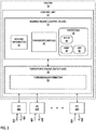
- FIG. 2 is a block diagram illustrating an example of a router, in accordance with the techniques of described in this disclosure.
- router 18 may represent any of routers 18 of FIG. 1 .
- Router 18 includes a control unit 32 that includes a routing engine 34.
- Router 18 includes interface cards 88A-88N (collectively, "IFCs 88") that send and receive packet flows via inbound network links 90A-90N (collectively, "inbound network links 90") and outbound network links 92A-92N (collectively, "outbound network links 92”), respectively.
- IFCs 88 are typically coupled to links 90, 92 via a number of interface ports (not shown).
- Inbound links 90 and outbound links 92 may represent physical interfaces, logical interfaces, or some combination thereof.
- Routing engine 34 provides an operating environment for various protocols 44 that execute at different layers of a network stack. Routing engine 34 is responsible for the maintenance of routing information 40 to reflect the current topology of a network and other network entities to which router 18 is connected. In particular, routing protocols periodically update routing information 40 to accurately reflect the topology of the network and other entities based on routing protocol messages received by router 18.
- the protocols may be software processes executing on one or more processors.
- routing engine 34 includes network protocols that operate at a network layer of the network stack. In the example of FIG. 2 , network protocols include TCP/IP 46.
- Routing engine 34 may also include various messaging protocols, including Internet Control Message Protocol (ICMP) 48 and User Datagram Protocol (UDP) 49 to implement traceroute techniques described in this disclosure.
- ICMP 48 may include ICMP version 4, as illustrated in Request for Comments (RFC) 792, titled “ Internet Control Message Protocol,” prepared by the Network Working Group of the Internet Engineering Task Force (IETF), dated September 1981 , and ICMP version 6, as illustrated in Request for Comments (RFC) 4443, titled "Internet Control Message Protocol (ICMPv6) for the Internet Protocol Version 6 (IPv6).
- Router 18 may use ICMP 48 to convey control information, such as an ICMP traceroute request, to source network device 12.
- UDP 49 may also provide a procedure for which router 18A may send traceroute messages to other network devices, as illustrated in Request for Comments (RFC) 768, titled " User Datagram Protocol,” dated August 28, 1980 .
- Routing engine 34 may include other routing and/or messaging protocols not shown in FIG. 2 .
- Routing engine 34 may also include a traceroute module 42.
- traceroute module 42 may execute in the control plane of router 18. Although the examples of traceroute module 42 are described with respect to the control plane, traceroute module 42 may be configured to execute in either the control plane, the forwarding plane, or both.
- router 18 may receive a traceroute packet including a TTL value from any of inbound links 90.
- forwarding engine 36 may decrement the TTL value and determine that the TTL value is not zero.
- traceroute module 42 may determine a number of paths from router 18 that are reachable to destination network device 14. Traceroute module 42 may configure an indicator to inform source network device 12 of the next-hop paths of the router. For example, traceroute module 42 may configure a new utility PDU packet to include a tally of the network paths available to router 18 that are reachable to the destination network device. In some examples, traceroute module 42 may include in the new utility PDU packet one or more network addresses of next-hop routers on those paths. Traceroute module 42 may forward the indicator to forwarding engine 36 such that the indicator is forwarded on any of outbound links 92 to source network device 12.
- Traceroute module 42 may also modify the traceroute packet to include an identifier of a corresponding path of a plurality of paths of router 18.
- router 18 may construct a new traceroute packet to include the identifier.
- router 18 may modify an existing traceroute packet to include the identifier.
- traceroute module 42 may modify a payload of the received traceroute packet to include a network address of router 18 and/or a session identifier to associate with a corresponding path for which the traceroute packet was forwarded to router 18.
- the traceroute packet may, as described above, include a current session-stack that comprises one or more network addresses of network devices that forwarded the traceroute packet and one or more session identifiers of the path for which the traceroute packet was forwarded. That is, the traceroute packet may identify the path from source network device 12 to router 18. In this way, traceroute module 42 may construct, for a corresponding path, an updated session-stack to include one or more network addresses from source network device 12 to router 18.
- router 18 may receive a traceroute packet including a TTL value from any of inbound links 90.
- Forwarding engine 36 may decrement the TTL value and determine that the TTL value is zero.
- forwarding engine 36 may forward the traceroute packet to routing engine 34 such that traceroute module 42 may configure an extended traceroute response, in accordance with the techniques described herein.
- traceroute module 42 may construct a TTL expired message to include a reverse-session-stack within a payload of the response that comprises an identifier associated with the corresponding path for which the traceroute packet was forwarded to router 18.
- traceroute module 42 may copy the session-stack received from the traceroute packet to the reverse-session-stack of the response. That is, the reverse-session-stack may comprise one or more network addresses leading up to router 18 and/or one or more session identifiers of the path for which the traceroute packet was forwarded to router 18.
- Forwarding engine 36 represents hardware and logic functions that provide high-speed forwarding of network traffic.
- Forwarding engine 36 typically includes a set of one or more forwarding chips programmed with forwarding information that maps network destinations with specific next hops and the corresponding output interface ports.
- forwarding engine 36 includes forwarding information 50.
- forwarding engine 36 maintains forwarding information 50 that associates network destinations with specific next hops and corresponding interface ports.
- routing engine 34 analyzes routing information 40 and generates forwarding information 50 in accordance with routing information 40.
- Forwarding information 50 may be maintained in the form of one or more tables, link lists, radix trees, databases, flat files, or any other data structures.
- router 18 illustrated in FIG. 2 is shown by way of example only. The disclosure is not limited to this architecture. In other examples, router 18 may be configured in a variety of ways. In one example, some of the functionality of routing engine 34 and forwarding engine 36 may be distributed within IFCs 88.
- control unit 32 may be implemented solely in software, or hardware, or may be implemented as combinations of software, hardware, or firmware.
- control unit 32 may include one or more processors, one or more microprocessors, digital signal processors (DSPs), application specific integrated circuits (ASICs), field programmable gate arrays (FPGAs), or any other equivalent integrated or discrete logic circuitry, or any combination thereof, which execute software instructions.
- DSPs digital signal processors
- ASICs application specific integrated circuits
- FPGAs field programmable gate arrays
- the various software modules of control unit 32 may comprise executable instructions stored, embodied, or encoded in a computer-readable medium, such as a computer-readable storage medium, containing instructions.
- Computer-readable storage media may include random access memory (RAM), read only memory (ROM), programmable read only memory (PROM), erasable programmable read only memory (EPROM), electronically erasable programmable read only memory (EEPROM), non-volatile random access memory (NVRAM), flash memory, a hard disk, a CD-ROM, a floppy disk, a cassette, a solid state drive, magnetic media, optical media, or other computer-readable media.
- Computer-readable media may be encoded with instructions corresponding to various aspects of router 18, e.g., protocols. Control unit 32, in some examples, retrieves and executes the instructions from memory for these aspects.
- FIG. 3 is a block diagram illustrating an example of a network device, such as source network device 12 of FIG. 1 , that allows administrator 16 to implement an extended traceroute utility to identify network paths of a network device with a plurality of paths, in accordance with the techniques described herein.
- source network device 12 includes interface cards 324A-324N (collectively, “IFCs 324") that send and receive packet flows via inbound network links 326A-326N (collectively, “inbound network links 326”) and outbound network links 328A-328N (collectively, “outbound network links 328”), respectively.
- IFCs 324 are coupled to control unit 320 by an input / output bus 330.
- control unit 320 provides an operating environment of executing software instructions stored within storage device 333.
- control unit 320 may include one or more programmable processors 334 capable of executing software instructions. Operating system 335, when executed by processor 334, provides an execution environment for software components, including diagnostic protocols such as traceroute 336.
- Traceroute 336 allows source network device 12 to output traceroute request packets, and receive traceroute response packets, as described herein.
- traceroute 336 may construct a traceroute packet comprising an identifier for one or more paths from source network device 12 that are reachable to destination network device 14.
- traceroute 336 may also construct the traceroute packet to include a network address of source network device 12.
- Traceroute 336 may also determine from one or more indicators received from routers 18 the number of paths a router has to reach destination network device 14. Based on the indicator, traceroute 336 may determine whether source network device 12 has received a response from each of the plurality of paths of the router. If source network device 12 has not received a response for each of the paths of the router, traceroute 336 may prevent source network device 12 from configuring a new traceroute packet with an incremented TTL value and may wait until source network device 12 receives a response for all paths of the router. If source network device 12 has received a response for all paths of the router, traceroute 336 may configure a traceroute tree based on the responses, and may also increment the TTL value and configure another traceroute packet.
- the source network device or the target network device may be any form of network device, and either or both of the devices may have one or more unnumbered interfaces.
- Examples of other devices include servers, laptops, desktops, mobile devices, intrusion detection devices, virtual private network (VPN) appliances, routers, hubs, switches, gateways, firewalls, security devices and other network devices and appliances.
- VPN virtual private network
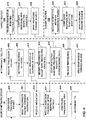
- FIG. 4 is a block diagram illustrating an example format of a traceroute packet 400 for use in tracing multiple paths of a network device, in accordance with the techniques described herein.
- traceroute packet 400 merely illustrated as an example and may include more or fewer data fields.
- Traceroute packet 400 includes a header 401 including at least a source port field 402, a destination port field 404, and a TTL value field 406.
- Source port field 402 may include source information for purposes of routing.
- source port field 402 may contain a source IP address of source network device 12.
- Destination port field 404 contains destination information.
- destination port field 404 may contain a destination IP address of destination network device 14.
- the TTL field 410 may include a value that indicates a maximum number of hops the packet can traverse on the way to the packet's destination prior to expiration.
- Length field 408 may include the length of traceroute packet 400.
- Checksum field 410 may be calculated taking into account the entire traceroute packet 400. Further information regarding UDP and the packet format of UDP can be found in Request for Comments (RFC) 768, titled " User Datagram Protocol," dated August 28, 1980 .
- RRC Request for Comments
- Payload 412 may include a "session-stack" as described in this disclosure.
- payload 412 may comprise a network device identifier ("DEV ID") field 414 and a session identifier ("SESSION ID”) field 416.
- DEV ID network device identifier
- SESSION ID session identifier
- a network device may enter a network device identifier (e.g., an IP address) of the source network device into network device identifier field 412, and may enter a session number into session identifier field 414 to associate a particular path of the source network device that is reachable to the destination network device.
- an intermediate network device e.g., router 18A
- that receives traceroute packet 400 with TTL value field 406 having a TTL value greater than one may modify payload 412 to include its network address in network device identifier field 414 and a session number associated with a particular path of the intermediate network device in session identifier field 416.
- router 18A may add to payload 412 its network address to device identifier field 412 and a respective session identifier associating with one of the paths to routers 18B and 18C in session identifier field 416.
- payload 410 may include a list of network addresses for source network device 12 and router 18A, and a respective session identifier to associate with the path to router 18B, for example.
- FIG. 5 is a block diagram illustrating an example format of a response 500 for use in tracing multiple paths of a network device, in accordance with the techniques described herein.
- Response 500 may, for example, be structured similar to an ICMP time exceeded packet and is configured by traceroute module 42 of FIG. 2 .
- Response 500 may include an IP header 502 that contains destination information for purposes of routing.
- IP header 502 may contain a source IP address, a destination IP address, and a Time to Live (TTL) value that indicates a maximum number of hops the packet can traverse on the way to the packet's destination prior to expiration.
- TTL Time to Live
- response 500 may include a header 503 having a type field 504, a code field 506, and a checksum 508.
- Type field 504 is used to identify the type of message. For example, a type value of "11" indicates that the packet is a time exceeded message. This type of packet is used by a traceroute utility to respond when a TTL value is zero.
- Code field 506 varies depending on the particular type of message, as specified by type field 504. For example, for a traceroute reply packet having type 11 ("time exceeded"), a code value of "0" indicates that the time to live expired while the packet was in transit.
- Checksum 508 may be calculated taking into account the entire packet. Further information regarding ICMP and the various packet formats of ICMP can be found in Request for Comments (RFC) 792, titled " Internet Control Message Protocol,” prepared by the Network Working Group of the Internet Engineering Task Force (IETF), dated September 1981 .
- RRC Request for Comments
- Payload 510 is extended to include a reverse-session-stack" as described in this disclosure.
- payload 510 may comprise a network device identifier ("DEV ID") field 512 and a session identifier ("SESSION ID") field 514.
- DEV ID network device identifier
- SESSION ID session identifier
- a target network device may configure a traceroute response packet 500 with payload 510 copied from the payload of a traceroute packet (as described in FIG. 4 ) received from a previous-hop. That is, the one or more device identifiers and one or more session identifiers included in the received traceroute packet is included in a payload 510 of response 500.
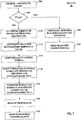
- FIG. 6 is a flowchart illustrating an example operation of network system 10, in accordance with the techniques described in this disclosure. For illustration purposes, FIG. 6 is explained with reference to source network device 12 of FIGS. 1 and 3 , and routers 18A-18C of FIGS. 1 and 2 . Although the examples described below are illustrated with respect to routers 18A-18C of FIGS. 1 and 2 , any of routers 18 may perform the described examples.
- Source network device 12 may configure a traceroute packet including an identifier associated with one or more paths from source network device 12 to destination network device and a TTL value (602). For example, an administrator may invoke the traceroute utility 336 of source network device 12 to configure a traceroute packet to include an identifier having a session-stack comprising a network address of source network device 12 and a session identifier to associate the one or more paths from the source network device to the destination network device. Source network device 12 may send the traceroute packet upstream towards destination network device 14 (604).
- An intermediate network device e.g., router 18A may receive the traceroute packet (606). As further described in FIG. 6 , router 18A may determine, based on the TTL value included with the traceroute packet, whether to forward the traceroute packet or to construct a response to the traceroute packet. In this example, router 18A may be illustrated to forward the traceroute packet.
- router 18A may determine a number of paths of router 18A that may reach the destination (608). In one example, router 18A may configure an indicator that includes the number of the paths for router 18A. In this example, router 18A may include an indicator representing the number of paths to routers 18B and 18C. In some examples, the indicator may further include one or more network addresses of next-hop devices on the paths, such as network addresses of routers 18B and 18C.
- Router 18A may send the indicator to source network device 12 (610).
- Source network device 12 may receive the indicator (612).
- Source network device 12 may determine based on the indicator the number of paths of router 18A.
- Router 18A may modify a payload of the traceroute packet to include a respective identifier associated with a corresponding path of router 18A (614). For example, router 18A may configure one respective modified traceroute packet including a session-stack comprising a network address of router 18A and a respective session identifier to associate a corresponding path to router 18B. Router 18A may also configure another respective modified traceroute packet including a session-stack comprising the network address of router 18A and a respective session identifier to associate a corresponding path to router 18C. That is, router 18A may construct respective modified traceroute packets for corresponding paths of router 18A. Router 18A may send the respective modified traceroute packets to their corresponding paths to target routers 18B and 18C (616).
- Target routers 18B and 18C may each receive a respective modified traceroute packet (618, 620). Each of routers 18B and 18C may, when the TTL value is one, configure a response to the modified traceroute packet (622, 624). As further described in FIG. 6 , the received modified traceroute packet is forwarded to a control plane of the target network device such that the target network device may configure a response.
- the response may include a reverse-session-stack copied from the session-stack received from router 18A. That is, the response for router 18B may include network addresses for source network device 12 and intermediate router 18A, and a session identifier associating the path from intermediate router 18A to target router 18B.
- the response for router 18C may include network addresses for source network device 12 and intermediate router 18A, and a session identifier associating the path from intermediate router 18A to target router 18C.
- Routers 18B and 18C may each send its response toward source network device 12 (626, 628). For example, in response to configuring the response, each of routers 18B and 18C may forward the response to its forwarding engine to forward the response on an outbound interface link to router 18A.
- Intermediate router 18A may receive the responses (630). Router 18A may receive the responses in parallel or sequentially. In any event, router 18A may send the responses from routers 18B and 18C toward source network device 12 (632).
- Source network device 12 may receive the responses on any of inbound interface links 328 and may determine whether source network device 12 has received a response for each of the plurality of network paths of a network device based on the received indicator (634). For example, based on the received indicator, the traceroute utility 336 of source network device 12 may determine that source network device 12 expects to receive a response for the path from router 18A to router 18B and another response for the path from router 18A to router 18C. In response to receiving a response for each of the network paths of router 18A, source network device 12 may then configure a traceroute tree based on the received responses (636), and configure a new traceroute packet with an incremented TTL value for which source network device 12 may send toward destination network device 14 (638). Source network device 12 may continue the process until receiving a response from a destination network device.
- FIG. 7 is a flowchart illustrating an example operation of router 18, in accordance with the techniques described in this disclosure.
- Router 18 of FIG. 7 may represent any of routers 18 of FIGS. 1 and 2 .
- Router 18 may receive a traceroute packet including a TTL value from one of inbound network links 90 (702).
- the forwarding engine 36 of router 18 may decrement the TTL value and determine whether the TTL value is zero (704). If the TTL value is zero, router 18 may forward the traceroute packet to routing engine 34 such that traceroute module 42 may construct a response to the traceroute packet.
- Traceroute module 42 of router 18 may construct a response including a respective identifier received from the traceroute packet (706). For example, router 18 may receive a traceroute packet that includes in its payload a session-stack comprising one or more network addresses of network devices that forwarded the traceroute packet and/or one or more session identifiers associated with paths for which the traceroute packet was forwarded on. In one example, router 18 may construct an extended TTL expired message including in a payload of the message a reverse-session-stack that copies the session-stack of the received traceroute packet. That is, the response may include the one or more network addresses of network devices that forwarded the traceroute packet and the one or more session identifiers associated with paths for which the traceroute packet was forwarded. Router 18 may forward the response to forwarding engine 36 to send the response on any of outbound links 92 toward source network device 12 (708).
- router 18 may determine a number of paths it has for reaching destination network device 14 (710). For example, traceroute module 42 of router 18 may perform a destination lookup to determine the paths reachable to destination network device 14. Traceroute module 42 may configure an indicator comprising the number of paths (712). In one example, router 18 may use traceroute module 42 to configure the indicator as a new utility PDU including the number of paths of router 18. In some examples, the new utility PDU may include one or more network addresses of next-hop network devices on the paths of router 18. Router 18 may send the indicator on any of outbound links 92 toward source network device 12 (714).
- Traceroute module 42 of router 18 may modify a payload of the traceroute packet to include a respective identifier for a corresponding path of router 18 (716).
- traceroute module 42 may modify the payload to include a session-stack comprising at least a network address of router 18 and a session identifier associated with a corresponding path of router 18 that may reach destination network device 14.
- Router 18 may forward the respective modified traceroute packet on the corresponding paths (718).
- traceroute module 42 may forward the respective modified traceroute packets to forwarding engine 36 to forward the respective modified traceroute packets on any of outbound links 92 toward the corresponding paths to the next-hops.
- Forwarding engine 36 of router 18 may receive one or more responses to the modified traceroute packet on any of inbound links 90 (720). Forwarding engine 36 of router 18 may identify from the response packet header that the responses are to be forward to source network device 12 on any of outbound links 92 toward source network device 12 (722).
- FIG. 8 is a flowchart illustrating an example operation of source network device 12, in accordance with the techniques described in this disclosure.
- source network device 12 represents source network device 12 of FIGS. 1 and 3 .
- Source network device 12 may configure a traceroute packet including a network identifier for a path available to source network device 12 to reach the destination network device (804). For example, source network device 12 may configure a payload of a traceroute packet with a "session-stack" comprising the network address of source network device 12 and/or a respective session identifier associated with the next-hop path from source network device 12. Source network device 12 may also configure a TTL value to indicate a maximum number of hops the packet can traverse on the way to the packet's destination prior to expiration.
- Source network device 12 sends the traceroute packet and TTL value via any of outbound links 328 towards destination network device 14 (806).
- source network device 12 may use the UDP protocol to communicate the traceroute packet as described herein to illicit responses from a target network device, e.g., router 18, along the path to the destination network device.
- source network device 12 may receive an indicator from an intermediary router including a number of paths available to the router for reaching the destination network device (808).
- the indicator may also include one or more network addresses of next-hop routers on those paths.
- Source network device 12 may receive one or more responses to the traceroute packet on any of inbound links 326 (810).
- Traceroute 336 of source network device 12 may determine based on the indicator received from the intermediary router whether source network device 12 has received a response from each of the plurality of paths of the intermediary router (812). If source network device 12 has not received a response for each of the paths of the intermediary router, source network device 12 may not configure a new traceroute packet with an incremented TTL value and may wait to receive one or more additional responses to the traceroute packet (810).
- source network device 12 may configure a traceroute tree based on the received one or more responses for each path of the intermediary router (814), and may also increment the TTL value (814) and configure another traceroute packet (804).
- the techniques described herein may be implemented in hardware, software, firmware, or any combination thereof.
- Various features described as modules, units or components may be implemented together in an integrated logic device or separately as discrete but interoperable logic devices or other hardware devices.
- various features of electronic circuitry may be implemented as one or more integrated circuit devices, such as an integrated circuit chip or chipset.
- this disclosure may be directed to an apparatus such a processor or an integrated circuit device, such as an integrated circuit chip or chipset.
- the techniques may be realized at least in part by a computer-readable data storage medium comprising instructions that, when executed, cause a processor to perform one or more of the methods described above.
- the computer-readable data storage medium may store such instructions for execution by a processor.
- a computer-readable medium may form part of a computer program product, which may include packaging materials.
- a computer-readable medium may comprise a computer data storage medium such as random access memory (RAM), read-only memory (ROM), non-volatile random access memory (NVRAM), electrically erasable programmable read-only memory (EEPROM), Flash memory, magnetic or optical data storage media, and the like.
- RAM random access memory
- ROM read-only memory
- NVRAM non-volatile random access memory
- EEPROM electrically erasable programmable read-only memory
- Flash memory magnetic or optical data storage media, and the like.
- an article of manufacture may comprise one or more computer-readable storage media.
- the computer-readable storage media may comprise non-transitory media.
- the term "non-transitory” may indicate that the storage medium is not embodied in a carrier wave or a propagated signal.
- a non-transitory storage medium may store data that can, over time, change (e.g., in RAM or cache).
- the code or instructions may be software and/or firmware executed by processing circuitry including one or more processors, such as one or more digital signal processors (DSPs), general purpose microprocessors, application-specific integrated circuits (ASICs), field-programmable gate arrays (FPGAs), or other equivalent integrated or discrete logic circuitry.
- DSPs digital signal processors
- ASICs application-specific integrated circuits
- FPGAs field-programmable gate arrays
- processors may refer to any of the foregoing structure or any other structure suitable for implementation of the techniques described herein.
- functionality described in this disclosure may be provided within software modules or hardware modules.
- a network device coupled to a plurality of paths and positioned between a source network device and destination network device may receive a traceroute packet.
- the network device may also, for each of the plurality of paths, modify a payload of the traceroute packet to include a respective identifier for a corresponding path of the plurality of paths to construct a respective modified traceroute packet for the corresponding path.
- the network device may also forward the respective modified traceroute packets on the corresponding paths.
Landscapes
- Engineering & Computer Science (AREA)
- Computer Networks & Wireless Communication (AREA)
- Signal Processing (AREA)
- Health & Medical Sciences (AREA)
- Cardiology (AREA)
- General Health & Medical Sciences (AREA)
- Data Exchanges In Wide-Area Networks (AREA)
Abstract
Description
- The present teaching relates to computer networks and, more particularly but not exclusively, to software utilities for determining the status of computer network connections.
- A computer network is a collection of interconnected computing devices that can exchange data and share resources. In a packet-based network, such as the Internet, the computing devices communicate data by dividing the data into small blocks called packets, which are individually routed across the network from a source device to a destination device. The destination device extracts the data from the packets and assembles the data into its original form.
- Certain devices, referred to as routers, maintain routing information that describes routes through the network. A "route" can generally be defined as a path between two locations on the network. Upon receiving an incoming packet, the router examines information within the packet to identify the destination for the packet. Based on the destination, the router forwards the packet in accordance with the routing information.
- Various software utilities exist for identifying failed connectivity between two nodes of a network and for exploring network topology. One such utility, referred to as traceroute, allows a source network device to identify a network path from the source network device to a destination network device. The traceroute utility determines the network path to a target network device by recording an Internet Control Message Protocol (ICMP) echo request packet's path from the source device to a specified network destination. As output, the traceroute typically displays how many hops the packet traveled to reach the network destination, identifies each hop along the path by its network address, and shows the round-trip time for reaching each hop.
- In general, this disclosure describes techniques for extending network connectivity software utilities, such as traceroute, to provide complete visibility into a network topology between a source device and a destination device, even when an intermediate network device may be actively utilizing multiple network links when forwarding packets toward the destination. For example, a network device in the network path, such as an intermediate router, may be configured to actively utilize multiple paths, i.e., links, when forwarding traffic to reach a destination network device. As one example, the intermediate device may be configured to generally apply equal cost multi-path for forwarding packets on any of a set of active links based on a hashing operation. As described herein, to facilitate exploration of the network topology of each of the multiple paths, the intermediate network device may utilize respective sessions to track forwarding of a corresponding traceroute packet along each of the active multiple paths. For example, in response to receiving a traceroute packet specifying the network destination, the intermediate network device may configure and output a respective modified traceroute packet on each of the corresponding paths leading from the network device toward the destination. The respective modified traceroute packets may each include a respective identifier associated with the corresponding path of the multiple paths. The network device forwards the respective modified traceroute packets along the corresponding paths such that each path may be traced by its respective traceroute packet. A subsequent network device along each of the paths, such as a next hop router or the destination device, receives the modified traceroute packet for a given path and configures a response to include an identifier associated with the corresponding path. In this way, the network device may associate the response with the particular path along which the modified traceroute packet was forwarded to the network device. When the source network device has received a response for each of the multiple active paths, the source network device updates the results of the traceroute utility to reflect each of the multiple paths within the network and configures a new traceroute packet with an incremented Time-to-Live (TTL) value and sends the traceroute packet towards the destination network device. The source network device continues this process until a response is received from the destination network device. In this way, the traceroute packets and the responses may provide source network device with complete visibility even when a given intermediate device may be actively forwarding packets destined for the destination, even for the same packet flow, along multiple network paths.
- In one example, a method may include receiving, by a network device coupled to a plurality of paths for reaching a destination network device and positioned between a source network device and the destination network device, a traceroute packet. The method may also include, for each of the plurality of paths, modifying, by the network device, a payload of the traceroute packet to include a respective identifier for a corresponding path of the plurality of paths to construct a respective modified traceroute packet for the corresponding path. The method may also include forwarding, by the network device, the respective modified traceroute packets on the corresponding paths.
- In another example, a method may include sending, by a source network device, a traceroute packet to an intermediate network device coupled to a plurality of paths for reaching a destination network device, wherein the intermediate network device is positioned between the source network device and the destination network device. The method may also include receiving, by the source network device and from the intermediate network device, one or more respective responses, wherein each of the one or more respective responses comprises a payload including a respective identifier for a corresponding path of the plurality of paths.
- In another example, a network device may include a plurality of network interfaces, each of the network interfaces coupled to a different one of a plurality of paths for reaching a destination network device, wherein the network device is positioned between a source network device and the destination network device. The network device may also include one or more hardware-based processors configured to: receive a traceroute packet destined for the destination device; for each of the plurality of paths, modify a payload of the traceroute packet to include a respective identifier for a corresponding path of the plurality of paths to construct a respective modified traceroute packet for the corresponding path; and forward the respective modified traceroute packets on the corresponding paths.
- In another example, a source network device may include one or more hardware-based processors configured to: send a traceroute packet toward a destination network device; and receive one or more respective responses, wherein each of the one or more respective responses comprises a payload including a respective identifier for a corresponding path of a plurality of paths of an intermediate network device, wherein the intermediate network device is positioned between the source network device and the destination network device.
- The details of one or more examples are set forth in the accompanying drawings and the description below. Other features, objects, and advantages will be apparent from the description and drawings, and from the claims.
-
-
FIG. 1 is a block diagram illustrating an example network system in which intermediate network devices have been enhanced so as to enable a software utility, such as traceroute, to trace and report on connectivity information from a source destination to a destination device, even when one or more of the intermediate network device utilize multiple, active links when forwarding packets of the utility toward the destination. -
FIG. 2 is a block diagram illustrating an example of a router, in accordance with the techniques of described in this disclosure. -
FIG. 3 is a block diagram illustrating an example of a network device, such as source network device ofFIG. 1 , that allows administrator to implement traceroute of a plurality of paths, in accordance with the techniques described herein. -
FIG. 4 is a block diagram illustrating an example format of a traceroute packet for use in tracing multiple paths, in accordance with the techniques described herein. -
FIG. 5 is a block diagram illustrating an example format of a response packet for use in tracing multiple paths, in accordance with the techniques described herein. -
FIG. 6 is a flowchart illustrating an example operation of network system, in accordance with the techniques described in this disclosure. -
FIG. 7 is a flowchart illustrating an example operation of network device, in accordance with the techniques described in this disclosure. -
FIG. 8 is a flowchart illustrating an example operation of source network device, in accordance with the techniques described in this disclosure. -
FIG. 1 is a block diagram illustrating an example network system in which intermediate network devices have been enhanced so as to enable a software utility, such as traceroute, to trace and report on connectivity information from a source destination to a destination device, even when one or more of the intermediate network device utilize multiple, active links when forwarding packets of the utility toward the destination. In the example ofFIG. 1 ,source network device 12 andnetwork device 18A-18E (collectively, "network devices 18" or "routers 18") support use of the extended traceroute that has been extended to facilitate exploration of a network topology of each of the multiple paths when forwarding traffic to reach a destination network device. - In this example,
network system 10 includessource network device 12 anddestination network device 14 connected acrossnetwork 8 via intermediate routers, switches, and other network devices, shown for purposes of examples asrouters 18. Network 8 may comprise a public network such as the Internet, a private network, such as those owned and operated by an enterprise or service provider or a combination of both public and private networks. As a result,network 8 may be alternatively referred to herein as a Service Provider (SP) network.Network 8 may include one or more Wide Area Networks (WANs), Local Area Networks (LANs), Virtual Local Area Networks (VLANs), Virtual Private Networks (VPNs), and/or another type of network. - In some examples,
network 8 may be an Internet Protocol (IP) network in whichrouters 18 use IP forwarding for transporting network packets. In other instances,network 8 may be a label switching network in which network devices such asrouters 18, often referred to as Label Switching Routers or LSRs, use Multi-Protocol Label Switching (MPLS) signaling protocols to establish Label Switched Paths (LSPs) for transporting the network packets received fromsource devices 12. The MPLS data-carrying mechanism ofnetwork 8 may be viewed as lying between layer 2 and layer 3 of the Open Systems Interconnection (OSI) model and is often referred to as a layer 2.5 protocol. Reference to layers followed by a numeral may refer to a particular layer of the OSI model. More information concerning the
OSI model can be found in a IEEE publication entitled "OSI Reference Model - the ISO Model of Architecture for Open Systems Interconnection," by Hubert Zimmermann, published in IEEE Transactions on Communications, vol. 28, no. 4, dated April 1980. Further information regarding
MPLS and the various features of MPLS, as well as, general architectural information regarding MPLS can be found in Request for Comments (RFC) 3031, titled "Multiprotocol Label Switching Architecture," prepared by the Network Working Group of the Internet Engineering Task Force (IETF), dated January 2001. - Although shown as a single network in
FIG. 1 ,network 8 may comprise any number of interconnected networks, either public or private, in which the various networks interconnect to form various virtual networks. In addition,network 8 may include a variety of other network devices for forwarding network traffic, such as additional routers, switches, or bridges. The particular configuration ofnetwork system 10 is merely an example, androuters 18 may reside in a single network or within multiple networks. Although described with respect to routers, aspects of the techniques are applicable to other network devices, such as bridges, switches, gateways, network caches, and network acceleration devices. - In the example of
FIG. 1 ,source network device 12 anddestination network device 14 may each be a personal computer, a laptop computer, a mobile telephone, a network telephone, a television set-top box, a network device integrated into a vehicle, a video game system, a point-of-sale device, a personal digital assistant, an intermediate network device, a network appliance, a supercomputer, a mainframe computer, or another type of device capable of interfacing with and communicating overnetwork 8. - A number of physical and/or
virtual communication links 15A-15H (collectively, "links 15") ofnetwork 8interconnect routers 18 to facilitate control and data communication between the routers. Physical links ofnetwork 8 may include, for example, Ethernet PHY, Synchronous Optical Networking (SONET)/Synchronous Digital Hierarchy (SDH), Lambda, or other Layer 2 data links that include packet transport capability. Logical links ofnetwork 8 may include, for example, an Ethernet Virtual LAN, an MPLS LSP, or an MPLS-TE LSP. - In this example,
source network device 12 connects to network 8 viaaccess link 15A,destination network device 14 connects to network 8 viaaccess links 15G and/or 15H, androuters 18 communicate via access links 15B-15F. Access links 15 may comprise wired and/or wireless communication links. The term "communication link," as used herein, comprises any form of transport medium, wired or wireless, and can include intermediate nodes such as network devices. Each of access links 15 may comprise, for instance, aspects of an asymmetric DSL network, WiMAX, a T-1 line, an Integrated Service Digital Network (ISDN), or wired Ethernet. -
Routers 18 maintain routing information that describes available routes throughnetwork 8. Upon receiving an incoming packet, the receiving router examines information within the packet and forwards the packet in accordance with the routing information. In order to maintain an accurate representation ofnetwork 8, the routers exchange routing information, e.g., bandwidth availability of links, in accordance with a defined routing protocol, such as an Interior Gateway Protocol (IGP), Open Shortest Path First (OSPF), Intermediate System - Intermediate System (IS-IS) or Routing Information Protocol (RIP). - Various routing protocols allow for "Equal-Cost Multipath" (ECMP) routing. ECMP provides a routing technique by which a router may forward packets destined for a particular destination device along any of a plurality of paths (links) of equal cost, in this example. A router implementing ECMP may identify, when forwarding a packet, which next-hop (path) of a plurality of next-hops to use, and may output the packet on a given link based on the selection. For example, the router may determine the next-hop using hash-threshold, Modulo-N, and/or Highest random weight (HRW) techniques. Further information regarding ECMP can be found in Request for Comments (RFC) 2991, titled "Multipath Issues in Unicast and Multicast Next-Hop Selection," prepared by the Network Working Group of the Internet Engineering Task Force (IETF), dated November 2000, and RFC 2992, titled "Analysis of an Equal-Cost Multi-Path Algorithm," IETF, dated November 2000. Although the paths in
FIG. 1 are illustrated with respect to Equal-Cost Multi-Path (ECMP) paths,network system 10 may include other types of multipath routing. The techniques described herein are not limited to ECMP topologies and may be advantageous in any network where an intermediate device is actively forward packets destined for a destination device, even traceroute packets targeting the destination device, along any of a plurality of paths toward the destination. Other examples include weighted ECMP. - For example, various software utilities, such as traceroute, are useful tools for identifying failed connectivity and for exploring network topology between two nodes of a network.
Source network device 12 may typically use traceroute to identify a network path fromsource network device 12 todestination network device 14. Using traceroute,source network device 12 sends a traceroute packet towardsdestination network device 14. -
Source network device 12 may implement traceroute and send a traceroute packet towarddestination network device 14 with an initial hop count, e.g., a Time-to-Live (TTL) value. At each hop, a receiving router (e.g., "intermediary router") processes the traceroute packet and decrements the hop count. When the hop count is zero, the router typically sends a response, e.g., TTL expired message, port-unreachable, and Error/TimeOut packets, back tosource network device 12 informing the source network device that the packet was received and the hop count has expired.Source network device 12 receives the response and configures a traceroute tree based on the response.Source network device 12 proceeds to send another traceroute packet with an incremented TTL value such that the traceroute packet reaches the next device in the path, and continues this process until the destination device is reached. - However, when a router, e.g.,
router 18A, is configured to forward packets toward a destination network using any of a plurality of active paths , each time a traceroute packet is sent with an incremented TTL value, the traceroute packet may use a different port number from previous traceroute packets. As such,router 18 A may forward the traceroute packet toward the destination network device along a different one of 15B, 15C since the port-number is often considered when calculating the next-hop hash, e.g., part of a 5-tuple. The 5-tuple within a header of a packet, such as the traceroute packet being forwarded, may include: <source network address, destination network address, source port, destination port, protocol>, for example. As such, the trace of a network path of a network device (e.g.,router 18A) applying ECMP or other technique to actively forward packets destined for the same destination along multiple paths often results in tracing different branches of the multiple paths. As a result, the traceroute responses do not provide source network device 12 a complete picture of each path ofrouter 18A's multiple paths, and the conventional traceroute utility provides incomplete or inaccurate results, if any. - In accordance with the techniques of this disclosure, intermediate devices, such as
routers 18, are configured to enhance the traceroute packets to provide complete visibility of multiple paths of a network device. For example, responsive to receiving a traceroute packet to be forwarded toward the destination, any ofrouters 18 currently applying ECMP or other technique to actively utilize multiple paths toward the destination may generate, configure and output a respective modified traceroute packet along each of the multiple paths such that each of the paths may be individually identified. - In operation,
administrator 16 accessessource network device 12 and invokes a diagnostic software utility, such as traceroute, to initiate a traceroute request. In response, the software utility executing onsource device 12 may configure a traceroute packet, e.g., protocol data unit (PDU) packet, with an identifier associated with a network path for which the traceroute packet is to be forwarded on. For example,source network device 12 may initially configure a traceroute packet with a TTL value of one and may include a "session-stack" in the traceroute payload comprising a network address ofsource network device 12 and a session identifier representing the path torouter 18A. That is, the session-stack may indicate the forwarding network device and the path that the packet was forwarded. For illustration purposes,source network device 12 may configure the session-stack as 10.1.1.1:1, which includes the IP address of source network device 12 (e.g., 10.1.1.1) and a session number of one that is associated with the single next-hop path fromsource device 12. -
Source network device 12 may send the traceroute packet upstream towardsdestination network device 14.Router 18A may receive the traceroute packet. In this example,router 18A may process the traceroute packet by decrementing the TTL value and determining whether the TTL value is zero. In this example,router 18A may determine that the TTL value is zero and may configure a response packet, e.g., a TTL expired packet, to include a payload having a "reverse-session-stack" with values copied from the received session-stack (e.g., 10.1.1.1:1).Router 18A sends the response packet back towardsource network device 12.Source network device 12 receives the response packet and may determine, based on the reverse-session-stack of the response packet, thatrouter 18A is the next-hop forsource device 12 along a single path viaaccess link 15A. - Continuing the traceroute process,
source device 12 may configure and send a new traceroute packet with an incremented TTL value towarddestination network device 14 to identify the one or more next-hops in the path. For example,source network device 12 may send another traceroute packet as described above (e.g., 10.1.1.1:1) with an incremented TTL value of two. Whenrouter 18A receives the traceroute packet,router 18A decrements the TTL value and determines that the TTL value is greater than one. In response,router 18A may forward the traceroute packet to a next-hop. - Prior to forwarding the traceroute packet,
router 18A may output a message to informsource network device 12 as to the number of active forwarding paths (links router 18A for reachingdestination network device 14. Becauserouter 18A is configured to select between any of the active multiple paths for the traceroute packet,router 18A may configure respective modified traceroute packets for each of the multiple paths. In the example ofFIG. 1 ,router 18A may perform a destination lookup on the received traceroute packet and determine, based on its internal routing information, that it is configured to forward packets destined for the destination along any of two active paths, i.e., the paths leading torouters Router 18A may informsource network device 12 as to the existence of the two viable paths for the traceroute packet. In some examples,router 18A may informsource network device 12 of the number of paths by configuring anindicator 13 such as a new utility PDU packet to include a tally of the next-hop paths and/or network addresses of next-hop routers on the next-hop paths. In the example ofFIG. 1 ,routers router 18A vialinks router 18B may have an IP address of 10.39.1.1 androuter 18C may have an IP address of 10.100.1.1.Router 18A may configure a new utility PDU packet as a list of strings, e.g., {2, 10.39.1.1, 10.100.1.1}, to informsource network device 12 thatrouter 18A has two next-hop paths torouters Router 18A may sendindicator 13 to sourcenetwork device 12. -
Source network device 12 may receiveindicator 13 and may delay constructing a new traceroute packet with an incremented TTL value until it determines, based onindicator 13, that it has received a response to the corresponding traceroute packets generated byrouter 18A and output along each of the multiple paths leading fromrouter 18A toward the destination. -
Router 18A may configure a respective modified traceroute packet to be forwarded to each of the paths torouters router 18A may modify the received traceroute packet to include a respective identifier associated with a path torouter 18B. In another example,router 18A may modify the received traceroute packet to include a respective identifier associated with a path torouter 18C. - In particular,
router 18A may configure respectiveidentifiers representing sessions router 18B androuter 18C, respectively. For example,router 18A may configure one modified traceroute packet to include an identifier representing the path torouter 18B, which is denoted bysession 16.Router 18A may send the modified traceroute packet torouter 18B viaaccess link 15B. - In another example,
router 18A may also configure another modified traceroute packet to include an identifier representing the path torouter 18C, which is denoted bysession 17.Router 18A may send this modified traceroute packet torouter 18C viaaccess link 15C. In some examples,router 18A may send the respective modified traceroute packets to the corresponding paths in parallel. In other examples,router 18A may send the respective modified traceroute packets to the corresponding paths sequentially. In any event,router 18A may send a respective modified traceroute packet on the corresponding paths to trace the next-hop along each of the paths torouters - For
session 16,router 18A may, for example, modify a payload of the traceroute packet to include a session-stack that comprises at least its network address (e.g., 192, 168.0.2) and a session identifier (e.g., 1) that associatesrouter 18A with the path torouter 18B vialink 15B.Router 18A may send the modified traceroute packet onaccess link 15B towardrouter 18B.Router 18B receives the modified traceroute packet, decrements the TTL value, and may determine that the TTL value is zero for whichrouter 18B is to constructresponse 20A. In this example,router 18B may configure a TTL expired packet with a reverse-session-stack that may include the session-stack value received fromrouter 18A (e.g., 10.1.1.1:1, 192.168.0.2:1). - For
session 17,router 18A may, for example, modify a payload of the traceroute packet to include a session-stack that comprises at least its network address (e.g., 192. 168.0.2) and a session number (e.g., 2) that associatesrouter 18A with the path torouter 18C vialink 15C (e.g., session 17).Router 18A may send the modified traceroute packet onaccess link 15C towardrouter 18C.Router 18C receives the modified traceroute packet, decrements the TTL value, and determines that the TTL value is zero for whichrouter 18C is to construct response 20B. In this example,router 18C may configure a TTL expired packet with a reverse-session-stack that includes the session-stack value received fromrouter 18A (e.g., 10.1.1.1:1, 192.168.0.2:2). -
Routers router 18A.Source network device 12 may receiveresponses 20A, 20B with their respective reverse-session stacks, and may determine, from the respective identifiers, thatrouter 18B is a next-hop for one path ofrouter 18A, androuter 18C is a next-hop for another path ofrouter 18A. For example,source network device 12 may receive fromrouter 18B a response including a reverse-session-stack of "10.1.1.1:1, 192.168.0.2:1" for whichsource network device 12 may determine thatrouter 18B is associated with session identifier "1," which represents the trace forsession 16.Source network device 12 may also receive fromrouter 18C a response including a reverse-session-stack of "10.1.1.1:1, 192,168.0.2:2" for whichsource network device 12 may determine thatrouter 18C is associated with session identifier "2," which represents the trace forsession 17. - As described above,
source network device 12 may determine fromindicator 13 thatrouter 18A has two paths. Based on the information fromindicator 13,source network device 12 may configure a new traceroute packet with an incremented TTL value when a response is received for all paths ofrouter 18A. For example, whensource network device 12 receives a response fromrouter 18B with an identifier of a path fromrouter 18A torouter 18B and a response fromrouter 18C with an identifier of a path fromrouter 18A torouter 18C,source network device 12 may determine, based onindicator 13, that a response was received for all paths ofrouter 18A. In response,router 18A may configure a traceroute tree of the paths ofrouter 18A and may configure a new traceroute packet with an incremented TTL value.Source network device 12 may send the new traceroute packet towardsdestination network device 14 to identify the next-hop in the path. - Continuing the above example,
source network device 12 may increment the TTL value to three and send a new traceroute packet (e.g., 10.1.1.1:1) towarddestination network device 14. Since the TTL value is greater than one,router 18A may forward the traceroute packet after modifying the traceroute packet to include its network address and a respective session identifier associated with a corresponding next-hop path connected to the router. - For
session 16,router 18A decrements the TTL value to two and modifies the received traceroute packet having a current session-stack (e.g., 10.1.1.1:1) to include the network address ofrouter 18A (e.g., 192.168.0.2) and a session number (e.g., 1) to construct a modified traceroute packet with an updated session-stack (e.g., 10.1.1.1:1, 192.168.0.2:1) that represents the path fromsource network device 12 torouter 18B. - When
router 18B receives the modified traceroute packet fromrouter 18A,router 18B decrements the TTL value and determines that the TTL value is not zero for whichrouter 18B is to forward the modified traceroute to its next-hop.Router 18B may perform a destination lookup and determine thatrouter 18B has a single path torouter 18D.Router 18B configures an indicator (not shown) to informsource network device 12 of the number of paths available torouter 18B. For example,router 18B may configure a new utility PDU packet as {1, 10.168.1.224}, which may include a tally of available next-hop paths (e.g., 1) torouter 18B and the network address ofrouter 18D (e.g., 10.168.1.224) that is coupled to the path.Router 18B may send the new utility PDU packet to sourcenetwork device 12 such thatsource network device 12 is informed of the number of paths forrouter 18B. - Prior to forwarding the modified traceroute packet,
router 18B may further modify the modified traceroute packet to include an identifier representing the path torouter 18D. In the example ofFIG. 1 ,router 18B may further modify the modified traceroute packet that has a current session-stack (e.g., 10.1.1.1:1, 192.168.0.2:1) to include its network address (e.g., 10.39.1.1) and a session identifier (e.g., 1) to construct a modified traceroute packet having an updated session-stack (e.g., 10.1.1.1:1, 192.168.0.2:1, 10.39.1.1:1) to represent a path fromsource network device 12 torouter 18D.Router 18B then sends the modified traceroute packet torouter 18D. -
Router 18D receives the modified traceroute packet, decrements the TTL value, and may determine that the TTL value is zero for whichrouter 18D is to construct a response. In this example,router 18D may configure a TTL expired packet with a reverse-session-stack copied from the updated session-stack received fromrouter 18B, and sends the response downstream towardsource network device 12.Source network device 12 may receive the response with the reverse-session-stack, and may determine, from an identifier in the updated session-stack, thatrouter 18D is a next-next-hop for one path ofrouter 18A. As a response was received from all paths ofrouter 18B,source network device 12 may update the traceroute tree to includerouters session 16 ofrouter 18A. - Similarly, for
session 17,router 18A decrements the TTL value to two and modifies the received traceroute packet having a current session-stack (e.g., 10.1.1.1:1) to include the network address ofrouter 18A (e.g., 192.168.0.2) and a session identifier (e.g., 2) to construct a modified traceroute packet with an updated session-stack (e.g., 10.1.1.1:1, 192.168.0.2:2) that represents the path fromrouter 18A torouter 18C. Whenrouter 18C receives the modified traceroute packet fromrouter 18A,router 18C decrements the TTL value and determines that the TTL value not zero for whichrouter 18C is to forward the modified traceroute packet to its next-hop.Router 18C may perform a destination lookup and determine that it has two paths torouters Router 18C may configure an indicator (not shown) to informsource network device 12 of the number of paths. For example,router 18D may configure a new utility PDU packet as {2, 10.168.1.224, 100.200.2.2}, which may include a tally of the available next-hops (e.g., 2) torouters router 18D (e.g., 10.168.1.224) androuter 18E (e.g., 100.200.2.2) that is coupled to the paths.Router 18D may send the indicator to sourcenetwork device 12 such thatsource network device 12 is informed of the number of paths forrouter 18D. - In one example,
router 18C may configure respectiveidentifiers representing sessions router 18D androuter 18E, respectively. For example,router 18C may configure one modified traceroute packet to include an identifier representing the path torouter 18D, which is denoted bysession 18.Router 18C may send the modified traceroute packet torouter 18D viaaccess link 15E. - In another example,
router 18C may also configure another modified traceroute packet to include an identifier representing the path torouter 18E, which is denoted bysession 19.Router 18C may send this modified traceroute packet torouter 18E viaaccess link 15F. In some examples,router 18C may send the respective modified traceroute packets to the corresponding paths in parallel, and in other examples, may send the respective modified traceroute packets to the corresponding paths sequentially. In any event,router 18C may send a respective modified traceroute packet on the corresponding paths to trace the next-hop along each of the paths torouters - For
session 18,router 18C may, for example, further modify the payload of the modified traceroute packet to include a session-stack comprising at least its network address (e.g., 10.100.1.1) and a session identifier (e.g., 1) that associatesrouter 18C with the path torouter 18D vialink 15E (e.g., session 18). That is,router 18C may modify the current session-stack (e.g., 10.1.1.1:1, 192.168.0.2:2) with the above information to construct an updated session-stack (e.g., 10.1.1.1:1, 192.168.0.2:2, 10.100.1.1:1) to represent the path torouter 18D.Router 18C may send the modified traceroute packet onaccess link 15E towardrouter 18D. -
Router 18D receives the modified traceroute packet, decrements the TTL value, and may determine that the TTL value is zero for whichrouter 18D is to constructresponse 21A. In this example,router 18D may configure a TTL expired packet with a reverse-session-stack that includes the session-stack value received fromrouter 18C.Router 18D sends the response with the reverse-session-stack downstream towardsource network device 12. - For
session 19,router 18C may, for example, further modify the payload of the modified traceroute packet to include a session-stack comprising at least its network address (e.g., 10.100.1.1) and a session identifier (e.g., 2) that associatesrouter 18C with the path torouter 18E vialink 15F (e.g., session 19). That is,router 18 C may modify the current session-stack (e.g., 10.1.1.1:1, 192.168.0.2:2) with the above information to construct an updated session-stack (e.g., 10.1.1.1:1, 192.168.0.2:2, 10.100.1.1:2) to represent the path torouter 18E.Router 18C may send the modified traceroute packet onaccess link 15F towardrouter 18E. -
Router 18E receives the modified traceroute packet, decrements the TTL value, and may determine that the TTL value is zero for whichrouter 18E is to constructresponse 21B. In this example,router 18E may configure a TTL expired packet with a reverse-session-stack that includes the session-stack received fromrouter 18C, and send the response downstream towardsource network device 12. -
Source network device 12 may receiveresponses router 18D is a next-hop for one path ofrouter 18C androuter 18E is a next-hop for another path ofrouter 18C. In accordance with the techniques described herein,source device 12 may determine that one path to reachrouter 18D includesrouters router 18D includesrouters source device 12 may trace the paths for each of the ECMP routes. For example,source network device 12 may receive fromrouter 18D a response including a reverse-session-stack of "10.1.1.1:1, 192.168.0.2:2, 10.100.1.1:1" for whichsource network device 12 may determine thatrouter 18D is associated with session identifier "1," which represents the trace forsession 18.Source network device 12 may also receive fromrouter 18E a response including a reverse-session-stack of "10.1.1.1:1, 192,168.0.2:2, 10.100.1.1:2" for whichsource network device 12 may determine thatrouter 18C is associated with session identifier "2," which represents the trace forsession 19. - When
source network device 12 receives all responses forsessions router 18C,source network device 12 may send a new traceroute packet with an incremented TTL value upstream towardsdestination network device 14.Source network device 12 continues this process until a response fromdestination network device 14 is received. As one example,source network device 12 may send a traceroute packet with a TTL value of four towardsdestination network device 14, such thatdestination device 14 receives the traceroute packet from eitherrouters source network device 12 may configure a final traceroute tree based on the responses, which is logically represented as: - 1.
Router 18A -Router 18B -Router 18D - Destination - 2.
Router 18A -Router 18C:- a.
Router 18A -Router 18C -Router 18D - Destination - b.
Router 18A -Router 18C -Router 18E - Destination
- a.
-
FIG. 2 is a block diagram illustrating an example of a router, in accordance with the techniques of described in this disclosure. In the example ofFIG. 2 ,router 18 may represent any ofrouters 18 ofFIG. 1 .Router 18 includes acontrol unit 32 that includes arouting engine 34.Router 18 includesinterface cards 88A-88N (collectively, "IFCs 88") that send and receive packet flows viainbound network links 90A-90N (collectively, "inbound network links 90") andoutbound network links 92A-92N (collectively, "outbound network links 92"), respectively. IFCs 88 are typically coupled to links 90, 92 via a number of interface ports (not shown). Inbound links 90 and outbound links 92 may represent physical interfaces, logical interfaces, or some combination thereof. - Routing
engine 34 provides an operating environment forvarious protocols 44 that execute at different layers of a network stack. Routingengine 34 is responsible for the maintenance of routinginformation 40 to reflect the current topology of a network and other network entities to whichrouter 18 is connected. In particular, routing protocols periodically update routinginformation 40 to accurately reflect the topology of the network and other entities based on routing protocol messages received byrouter 18. The protocols may be software processes executing on one or more processors. For example, routingengine 34 includes network protocols that operate at a network layer of the network stack. In the example ofFIG. 2 , network protocols include TCP/IP 46. - Routing
engine 34 may also include various messaging protocols, including Internet Control Message Protocol (ICMP) 48 and User Datagram Protocol (UDP) 49 to implement traceroute techniques described in this disclosure.ICMP 48 may include ICMP version 4, as illustrated in Request for Comments (RFC) 792, titled "Internet Control Message Protocol," prepared by the Network Working Group of the Internet Engineering Task Force (IETF), dated September 1981, and ICMP version 6, as illustrated in Request for Comments (RFC) 4443, titled "Internet Control Message Protocol (ICMPv6) for the Internet Protocol Version 6 (IPv6).Router 18 may useICMP 48 to convey control information, such as an ICMP traceroute request, to sourcenetwork device 12.UDP 49 may also provide a procedure for whichrouter 18A may send traceroute messages to other network devices, as illustrated in Request for Comments (RFC) 768, titled "User Datagram Protocol," dated August 28, 1980. Routingengine 34 may include other routing and/or messaging protocols not shown inFIG. 2 . - Routing
engine 34 may also include atraceroute module 42. In one example,traceroute module 42 may execute in the control plane ofrouter 18. Although the examples oftraceroute module 42 are described with respect to the control plane,traceroute module 42 may be configured to execute in either the control plane, the forwarding plane, or both. - In one example,
router 18 may receive a traceroute packet including a TTL value from any of inbound links 90. In one example, forwardingengine 36 may decrement the TTL value and determine that the TTL value is not zero. In this example,traceroute module 42 may determine a number of paths fromrouter 18 that are reachable todestination network device 14.Traceroute module 42 may configure an indicator to informsource network device 12 of the next-hop paths of the router. For example,traceroute module 42 may configure a new utility PDU packet to include a tally of the network paths available torouter 18 that are reachable to the destination network device. In some examples,traceroute module 42 may include in the new utility PDU packet one or more network addresses of next-hop routers on those paths.Traceroute module 42 may forward the indicator to forwardingengine 36 such that the indicator is forwarded on any of outbound links 92 to sourcenetwork device 12. -
Traceroute module 42 may also modify the traceroute packet to include an identifier of a corresponding path of a plurality of paths ofrouter 18. In some examples,router 18 may construct a new traceroute packet to include the identifier. In other examples,router 18 may modify an existing traceroute packet to include the identifier. - In any event,
traceroute module 42 may modify a payload of the received traceroute packet to include a network address ofrouter 18 and/or a session identifier to associate with a corresponding path for which the traceroute packet was forwarded torouter 18. In some examples, the traceroute packet may, as described above, include a current session-stack that comprises one or more network addresses of network devices that forwarded the traceroute packet and one or more session identifiers of the path for which the traceroute packet was forwarded. That is, the traceroute packet may identify the path fromsource network device 12 torouter 18. In this way,traceroute module 42 may construct, for a corresponding path, an updated session-stack to include one or more network addresses fromsource network device 12 torouter 18. - In another example,
router 18 may receive a traceroute packet including a TTL value from any of inbound links 90. Forwardingengine 36 may decrement the TTL value and determine that the TTL value is zero. In response, forwardingengine 36 may forward the traceroute packet torouting engine 34 such thattraceroute module 42 may configure an extended traceroute response, in accordance with the techniques described herein. For example,traceroute module 42 may construct a TTL expired message to include a reverse-session-stack within a payload of the response that comprises an identifier associated with the corresponding path for which the traceroute packet was forwarded torouter 18. In one example,traceroute module 42 may copy the session-stack received from the traceroute packet to the reverse-session-stack of the response. That is, the reverse-session-stack may comprise one or more network addresses leading up torouter 18 and/or one or more session identifiers of the path for which the traceroute packet was forwarded torouter 18. - Forwarding
engine 36 represents hardware and logic functions that provide high-speed forwarding of network traffic. Forwardingengine 36 typically includes a set of one or more forwarding chips programmed with forwarding information that maps network destinations with specific next hops and the corresponding output interface ports. In the example ofFIG. 2 , forwardingengine 36 includes forwardinginformation 50. In accordance with routinginformation 40, forwardingengine 36 maintains forwardinginformation 50 that associates network destinations with specific next hops and corresponding interface ports. For example, routingengine 34 analyzes routinginformation 40 and generates forwardinginformation 50 in accordance with routinginformation 40. Forwardinginformation 50 may be maintained in the form of one or more tables, link lists, radix trees, databases, flat files, or any other data structures. - The architecture of
router 18 illustrated inFIG. 2 is shown by way of example only. The disclosure is not limited to this architecture. In other examples,router 18 may be configured in a variety of ways. In one example, some of the functionality ofrouting engine 34 and forwardingengine 36 may be distributed within IFCs 88. - Elements of
control unit 32 may be implemented solely in software, or hardware, or may be implemented as combinations of software, hardware, or firmware. For example,control unit 32 may include one or more processors, one or more microprocessors, digital signal processors (DSPs), application specific integrated circuits (ASICs), field programmable gate arrays (FPGAs), or any other equivalent integrated or discrete logic circuitry, or any combination thereof, which execute software instructions. In that case, the various software modules ofcontrol unit 32 may comprise executable instructions stored, embodied, or encoded in a computer-readable medium, such as a computer-readable storage medium, containing instructions. Instructions embedded or encoded in a computer-readable medium may cause a programmable processor, or other processor, to perform the method, e.g., when the instructions are executed. Computer-readable storage media may include random access memory (RAM), read only memory (ROM), programmable read only memory (PROM), erasable programmable read only memory (EPROM), electronically erasable programmable read only memory (EEPROM), non-volatile random access memory (NVRAM), flash memory, a hard disk, a CD-ROM, a floppy disk, a cassette, a solid state drive, magnetic media, optical media, or other computer-readable media. Computer-readable media may be encoded with instructions corresponding to various aspects ofrouter 18, e.g., protocols.Control unit 32, in some examples, retrieves and executes the instructions from memory for these aspects. -
FIG. 3 is a block diagram illustrating an example of a network device, such assource network device 12 ofFIG. 1 , that allowsadministrator 16 to implement an extended traceroute utility to identify network paths of a network device with a plurality of paths, in accordance with the techniques described herein. - In this example,
source network device 12 includesinterface cards 324A-324N (collectively, "IFCs 324") that send and receive packet flows viainbound network links 326A-326N (collectively, "inbound network links 326") andoutbound network links 328A-328N (collectively, "outbound network links 328"), respectively. IFCs 324 are coupled to controlunit 320 by an input /output bus 330. In general,control unit 320 provides an operating environment of executing software instructions stored withinstorage device 333. - For example,
control unit 320 may include one or moreprogrammable processors 334 capable of executing software instructions.Operating system 335, when executed byprocessor 334, provides an execution environment for software components, including diagnostic protocols such astraceroute 336.Traceroute 336 allowssource network device 12 to output traceroute request packets, and receive traceroute response packets, as described herein. For example,traceroute 336 may construct a traceroute packet comprising an identifier for one or more paths fromsource network device 12 that are reachable todestination network device 14. In some examples,traceroute 336 may also construct the traceroute packet to include a network address ofsource network device 12. -
Traceroute 336 may also determine from one or more indicators received fromrouters 18 the number of paths a router has to reachdestination network device 14. Based on the indicator,traceroute 336 may determine whethersource network device 12 has received a response from each of the plurality of paths of the router. Ifsource network device 12 has not received a response for each of the paths of the router,traceroute 336 may preventsource network device 12 from configuring a new traceroute packet with an incremented TTL value and may wait untilsource network device 12 receives a response for all paths of the router. Ifsource network device 12 has received a response for all paths of the router,traceroute 336 may configure a traceroute tree based on the responses, and may also increment the TTL value and configure another traceroute packet. - Although described with respect to a computer, the source network device or the target network device may be any form of network device, and either or both of the devices may have one or more unnumbered interfaces. Examples of other devices include servers, laptops, desktops, mobile devices, intrusion detection devices, virtual private network (VPN) appliances, routers, hubs, switches, gateways, firewalls, security devices and other network devices and appliances.
-
FIG. 4 is a block diagram illustrating an example format of atraceroute packet 400 for use in tracing multiple paths of a network device, in accordance with the techniques described herein. In the example ofFIG. 4 ,traceroute packet 400 merely illustrated as an example and may include more or fewer data fields. -
Traceroute packet 400 includes aheader 401 including at least asource port field 402, adestination port field 404, and aTTL value field 406.Source port field 402 may include source information for purposes of routing. For example,source port field 402 may contain a source IP address ofsource network device 12.Destination port field 404 contains destination information. For example,destination port field 404 may contain a destination IP address ofdestination network device 14. TheTTL field 410 may include a value that indicates a maximum number of hops the packet can traverse on the way to the packet's destination prior to expiration.Length field 408 may include the length oftraceroute packet 400.Checksum field 410 may be calculated taking into account theentire traceroute packet 400. Further information regarding UDP and the packet format of UDP can be found in Request for Comments (RFC) 768, titled "User Datagram Protocol," dated August 28, 1980. -
Payload 412 may include a "session-stack" as described in this disclosure. For example,payload 412 may comprise a network device identifier ("DEV ID")field 414 and a session identifier ("SESSION ID")field 416. For example, when traceroute is initiated at a source network device, a network device may enter a network device identifier (e.g., an IP address) of the source network device into networkdevice identifier field 412, and may enter a session number intosession identifier field 414 to associate a particular path of the source network device that is reachable to the destination network device. As the packet traverses the network, an intermediate network device, e.g.,router 18A, that receivestraceroute packet 400 withTTL value field 406 having a TTL value greater than one may modifypayload 412 to include its network address in networkdevice identifier field 414 and a session number associated with a particular path of the intermediate network device insession identifier field 416. For example,router 18A may add topayload 412 its network address todevice identifier field 412 and a respective session identifier associating with one of the paths torouters session identifier field 416. In this way,payload 410 may include a list of network addresses forsource network device 12 androuter 18A, and a respective session identifier to associate with the path torouter 18B, for example. -
FIG. 5 is a block diagram illustrating an example format of aresponse 500 for use in tracing multiple paths of a network device, in accordance with the techniques described herein.Response 500 may, for example, be structured similar to an ICMP time exceeded packet and is configured bytraceroute module 42 ofFIG. 2 .Response 500 may include anIP header 502 that contains destination information for purposes of routing. For example,IP header 502 may contain a source IP address, a destination IP address, and a Time to Live (TTL) value that indicates a maximum number of hops the packet can traverse on the way to the packet's destination prior to expiration. - In addition,
response 500 may include aheader 503 having atype field 504, acode field 506, and achecksum 508.Type field 504 is used to identify the type of message. For example, a type value of "11" indicates that the packet is a time exceeded message. This type of packet is used by a traceroute utility to respond when a TTL value is zero.Code field 506 varies depending on the particular type of message, as specified bytype field 504. For example, for a traceroute reply packet having type 11 ("time exceeded"), a code value of "0" indicates that the time to live expired while the packet was in transit.Checksum 508 may be calculated taking into account the entire packet. Further information regarding ICMP and the various packet formats of ICMP can be found in Request for Comments (RFC) 792, titled "Internet Control Message Protocol," prepared by the Network Working Group of the Internet Engineering Task Force (IETF), dated September 1981. -
Payload 510 is extended to include a reverse-session-stack" as described in this disclosure. For example,payload 510 may comprise a network device identifier ("DEV ID")field 512 and a session identifier ("SESSION ID")field 514. When a target network device receives a traceroute packet with an IP header having a TTL value of one, the target network device may configure atraceroute response packet 500 withpayload 510 copied from the payload of a traceroute packet (as described inFIG. 4 ) received from a previous-hop. That is, the one or more device identifiers and one or more session identifiers included in the received traceroute packet is included in apayload 510 ofresponse 500. -
FIG. 6 is a flowchart illustrating an example operation ofnetwork system 10, in accordance with the techniques described in this disclosure. For illustration purposes,FIG. 6 is explained with reference tosource network device 12 ofFIGS. 1 and3 , androuters 18A-18C ofFIGS. 1 and2 . Although the examples described below are illustrated with respect torouters 18A-18C ofFIGS. 1 and2 , any ofrouters 18 may perform the described examples. -
Source network device 12 may configure a traceroute packet including an identifier associated with one or more paths fromsource network device 12 to destination network device and a TTL value (602). For example, an administrator may invoke thetraceroute utility 336 ofsource network device 12 to configure a traceroute packet to include an identifier having a session-stack comprising a network address ofsource network device 12 and a session identifier to associate the one or more paths from the source network device to the destination network device.Source network device 12 may send the traceroute packet upstream towards destination network device 14 (604). - An intermediate network device, e.g.,
router 18A, may receive the traceroute packet (606). As further described inFIG. 6 ,router 18A may determine, based on the TTL value included with the traceroute packet, whether to forward the traceroute packet or to construct a response to the traceroute packet. In this example,router 18A may be illustrated to forward the traceroute packet. - Prior to forwarding the traceroute packet,
router 18A may determine a number of paths ofrouter 18A that may reach the destination (608). In one example,router 18A may configure an indicator that includes the number of the paths forrouter 18A. In this example,router 18A may include an indicator representing the number of paths torouters routers -
Router 18A may send the indicator to source network device 12 (610).Source network device 12 may receive the indicator (612).Source network device 12 may determine based on the indicator the number of paths ofrouter 18A. -
Router 18A may modify a payload of the traceroute packet to include a respective identifier associated with a corresponding path ofrouter 18A (614). For example,router 18A may configure one respective modified traceroute packet including a session-stack comprising a network address ofrouter 18A and a respective session identifier to associate a corresponding path torouter 18B.Router 18A may also configure another respective modified traceroute packet including a session-stack comprising the network address ofrouter 18A and a respective session identifier to associate a corresponding path torouter 18C. That is,router 18A may construct respective modified traceroute packets for corresponding paths ofrouter 18A.Router 18A may send the respective modified traceroute packets to their corresponding paths to targetrouters -
Target routers routers FIG. 6 , the received modified traceroute packet is forwarded to a control plane of the target network device such that the target network device may configure a response. In one example, the response may include a reverse-session-stack copied from the session-stack received fromrouter 18A. That is, the response forrouter 18B may include network addresses forsource network device 12 andintermediate router 18A, and a session identifier associating the path fromintermediate router 18A to targetrouter 18B. Similarly, the response forrouter 18C may include network addresses forsource network device 12 andintermediate router 18A, and a session identifier associating the path fromintermediate router 18A to targetrouter 18C. -
Routers routers router 18A. -
Intermediate router 18A may receive the responses (630).Router 18A may receive the responses in parallel or sequentially. In any event,router 18A may send the responses fromrouters -
Source network device 12 may receive the responses on any of inbound interface links 328 and may determine whethersource network device 12 has received a response for each of the plurality of network paths of a network device based on the received indicator (634). For example, based on the received indicator, thetraceroute utility 336 ofsource network device 12 may determine thatsource network device 12 expects to receive a response for the path fromrouter 18A torouter 18B and another response for the path fromrouter 18A torouter 18C. In response to receiving a response for each of the network paths ofrouter 18A,source network device 12 may then configure a traceroute tree based on the received responses (636), and configure a new traceroute packet with an incremented TTL value for whichsource network device 12 may send toward destination network device 14 (638).Source network device 12 may continue the process until receiving a response from a destination network device. -
FIG. 7 is a flowchart illustrating an example operation ofrouter 18, in accordance with the techniques described in this disclosure.Router 18 ofFIG. 7 may represent any ofrouters 18 ofFIGS. 1 and2 . -
Router 18 may receive a traceroute packet including a TTL value from one of inbound network links 90 (702). The forwardingengine 36 ofrouter 18 may decrement the TTL value and determine whether the TTL value is zero (704). If the TTL value is zero,router 18 may forward the traceroute packet torouting engine 34 such thattraceroute module 42 may construct a response to the traceroute packet. -
Traceroute module 42 ofrouter 18 may construct a response including a respective identifier received from the traceroute packet (706). For example,router 18 may receive a traceroute packet that includes in its payload a session-stack comprising one or more network addresses of network devices that forwarded the traceroute packet and/or one or more session identifiers associated with paths for which the traceroute packet was forwarded on. In one example,router 18 may construct an extended TTL expired message including in a payload of the message a reverse-session-stack that copies the session-stack of the received traceroute packet. That is, the response may include the one or more network addresses of network devices that forwarded the traceroute packet and the one or more session identifiers associated with paths for which the traceroute packet was forwarded.Router 18 may forward the response to forwardingengine 36 to send the response on any of outbound links 92 toward source network device 12 (708). - If the TTL value is not zero, then
router 18 may determine a number of paths it has for reaching destination network device 14 (710). For example,traceroute module 42 ofrouter 18 may perform a destination lookup to determine the paths reachable todestination network device 14.Traceroute module 42 may configure an indicator comprising the number of paths (712). In one example,router 18 may usetraceroute module 42 to configure the indicator as a new utility PDU including the number of paths ofrouter 18. In some examples, the new utility PDU may include one or more network addresses of next-hop network devices on the paths ofrouter 18.Router 18 may send the indicator on any of outbound links 92 toward source network device 12 (714). -
Traceroute module 42 ofrouter 18 may modify a payload of the traceroute packet to include a respective identifier for a corresponding path of router 18 (716). In one example,traceroute module 42 may modify the payload to include a session-stack comprising at least a network address ofrouter 18 and a session identifier associated with a corresponding path ofrouter 18 that may reachdestination network device 14. -
Router 18 may forward the respective modified traceroute packet on the corresponding paths (718). For example,traceroute module 42 may forward the respective modified traceroute packets to forwardingengine 36 to forward the respective modified traceroute packets on any of outbound links 92 toward the corresponding paths to the next-hops. - Forwarding
engine 36 ofrouter 18 may receive one or more responses to the modified traceroute packet on any of inbound links 90 (720). Forwardingengine 36 ofrouter 18 may identify from the response packet header that the responses are to be forward to sourcenetwork device 12 on any of outbound links 92 toward source network device 12 (722). -
FIG. 8 is a flowchart illustrating an example operation ofsource network device 12, in accordance with the techniques described in this disclosure. In the example ofFIG. 8 ,source network device 12 representssource network device 12 ofFIGS. 1 and3 . - An administrator may use
source network device 12 to initiate a traceroute utility 336 (802).Source network device 12 may configure a traceroute packet including a network identifier for a path available to sourcenetwork device 12 to reach the destination network device (804). For example,source network device 12 may configure a payload of a traceroute packet with a "session-stack" comprising the network address ofsource network device 12 and/or a respective session identifier associated with the next-hop path fromsource network device 12.Source network device 12 may also configure a TTL value to indicate a maximum number of hops the packet can traverse on the way to the packet's destination prior to expiration. -
Source network device 12 sends the traceroute packet and TTL value via any of outbound links 328 towards destination network device 14 (806). For example,source network device 12 may use the UDP protocol to communicate the traceroute packet as described herein to illicit responses from a target network device, e.g.,router 18, along the path to the destination network device. - As the traceroute packet traverses through the network,
source network device 12 may receive an indicator from an intermediary router including a number of paths available to the router for reaching the destination network device (808). In some examples, the indicator may also include one or more network addresses of next-hop routers on those paths. -
Source network device 12 may receive one or more responses to the traceroute packet on any of inbound links 326 (810).Traceroute 336 ofsource network device 12 may determine based on the indicator received from the intermediary router whethersource network device 12 has received a response from each of the plurality of paths of the intermediary router (812). Ifsource network device 12 has not received a response for each of the paths of the intermediary router,source network device 12 may not configure a new traceroute packet with an incremented TTL value and may wait to receive one or more additional responses to the traceroute packet (810). Ifsource network device 12 has received a response for each of the plurality of paths of the intermediary router,source network device 12 may configure a traceroute tree based on the received one or more responses for each path of the intermediary router (814), and may also increment the TTL value (814) and configure another traceroute packet (804). - The techniques described herein may be implemented in hardware, software, firmware, or any combination thereof. Various features described as modules, units or components may be implemented together in an integrated logic device or separately as discrete but interoperable logic devices or other hardware devices. In some cases, various features of electronic circuitry may be implemented as one or more integrated circuit devices, such as an integrated circuit chip or chipset.
- If implemented in hardware, this disclosure may be directed to an apparatus such a processor or an integrated circuit device, such as an integrated circuit chip or chipset. Alternatively or additionally, if implemented in software or firmware, the techniques may be realized at least in part by a computer-readable data storage medium comprising instructions that, when executed, cause a processor to perform one or more of the methods described above. For example, the computer-readable data storage medium may store such instructions for execution by a processor.
- A computer-readable medium may form part of a computer program product, which may include packaging materials. A computer-readable medium may comprise a computer data storage medium such as random access memory (RAM), read-only memory (ROM), non-volatile random access memory (NVRAM), electrically erasable programmable read-only memory (EEPROM), Flash memory, magnetic or optical data storage media, and the like. In some examples, an article of manufacture may comprise one or more computer-readable storage media.
- In some examples, the computer-readable storage media may comprise non-transitory media. The term "non-transitory" may indicate that the storage medium is not embodied in a carrier wave or a propagated signal. In certain examples, a non-transitory storage medium may store data that can, over time, change (e.g., in RAM or cache).
- The code or instructions may be software and/or firmware executed by processing circuitry including one or more processors, such as one or more digital signal processors (DSPs), general purpose microprocessors, application-specific integrated circuits (ASICs), field-programmable gate arrays (FPGAs), or other equivalent integrated or discrete logic circuitry. Accordingly, the term "processor," as used herein may refer to any of the foregoing structure or any other structure suitable for implementation of the techniques described herein. In addition, in some aspects, functionality described in this disclosure may be provided within software modules or hardware modules.
- Therefore, from one perspective there have been described, techniques for extending network connectivity software utilities, such as traceroute, to provide complete visibility into a network topology between a source device and a destination device, even when an intermediate network device may be actively utilizing multiple network links when forwarding packets toward the destination. In one example, a network device coupled to a plurality of paths and positioned between a source network device and destination network device may receive a traceroute packet. The network device may also, for each of the plurality of paths, modify a payload of the traceroute packet to include a respective identifier for a corresponding path of the plurality of paths to construct a respective modified traceroute packet for the corresponding path. The network device may also forward the respective modified traceroute packets on the corresponding paths.
- In addition to or as an alternative to the above, the following examples are described. The features described in any of the following examples may be utilized with any of the other examples described herein.
- Example 1. A method comprising: receiving, by a network device coupled to a plurality of paths for reaching a destination network device and positioned between a source network device and the destination network device, a traceroute packet; for each of the plurality of paths, modifying, by the network device, a payload of the traceroute packet to include a respective identifier for a corresponding path of the plurality of paths to construct a respective modified traceroute packet for the corresponding path; forwarding, by the network device, the respective modified traceroute packets on the corresponding paths.
- Example 2. The method of example 1, wherein receiving the traceroute packet comprises: receiving one or more network addresses of one or more intermediate network devices that forwarded the traceroute packet on a path to the network device, wherein the one or more intermediate network devices are positioned between the network device and the source network device; and receiving one or more session identifiers associated with the path to the network device for which the one or more intermediate network devices forwarded the traceroute packet.
- Example 3. The method of example 1 or 2, wherein modifying the payload of the traceroute packet to include the respective identifier further comprises modifying the payload of the traceroute packet to include a network address of the network device.
- Example 4. The method of example 1, 2 or 3, further comprising: configuring, by the network device, an indicator representing a number of the plurality of paths of the network device; and sending, by the network device, the indicator to the source network device.
- Example 5. The method of example 4, wherein configuring the indicator further comprises configuring the indicator to include one or more network addresses of one or more next-hops on the plurality of paths of the network device.
- Example 6. The method of any of examples 1 to 5, further comprising: determining, by the network device, whether the traceroute packet includes a TTL value of zero; and in response to determining the TTL value is zero, constructing, by the network device, a response comprising a respective identifier included with traceroute packet.
- Example 7. The method of example 6, wherein constructing the response comprising the respective identifier further comprises: constructing the response to include one or more network addresses of one or more intermediate network devices that forwarded the traceroute packet to the network device, wherein the one or more intermediate network devices are positioned between the network device and the source network device; and sending, by the network device, the response towards the source network device.
- Example 8. The method of example 6 or 7, wherein configuring the response to the traceroute packet comprises configuring an Internet Control Message Protocol (ICMP) packet.
- Example 9. The method of any of examples 1 to 8, wherein the plurality of paths comprises a plurality of Equal Cost Multi-Path (ECMP) paths.
- Example 10. A method comprising: sending, by a source network device, a traceroute packet to an intermediate network device coupled to a plurality of paths for reaching a destination network device, wherein the intermediate network device is positioned between the source network device and the destination network device; and receiving, by the source network device and from the intermediate network device, one or more respective responses, wherein each of the one or more respective responses comprises a payload including a respective identifier for a corresponding path of the plurality of paths.
- Example 11. The method of example 10, wherein receiving the one or more respective responses comprises: receiving one or more network addresses of one or more network devices that forwarded the traceroute packet on the corresponding path.
- Example 12. The method of example 10 or 11, further comprising: receiving, by the source network device and from the intermediate network device, an indicator representing a number of the plurality of paths of the intermediate network device; determining, by the source network device and based on the indicator, whether the source network device has received a respective response for each of a plurality of traceroute packets generated by the intermediate network device and output on respective ones of the plurality of paths toward the destination network device; and in response to determining the source network device has received the respective response for each of the plurality of paths, configuring, by the source network device, another traceroute packet with an incremented TTL value.
- Example 13. The method of example 12, further comprising: in response to determining the source network device has received the respective response for each of the plurality of paths, constructing, by the source network device and based on the responses, a traceroute tree for each of the plurality of paths.
- Example 14. The method of any of examples 10 to 13, wherein sending the traceroute packet comprises sending an identifier for one or more paths from the source network device to the destination network device.
- Example 15. The method of example 14, wherein sending the traceroute packet further comprises sending a network address of the source network device.
- Example 16. The method of any of examples 10 to 15, wherein the respective identifier of the corresponding path further comprises: one or more network addresses of the one or more network devices that forwarded the traceroute packet on the corresponding path.
- Example 17. A network device comprising: a plurality of network interfaces, each of the network interfaces coupled to a different one of a plurality of paths for reaching a destination network device, wherein the network device is positioned between a source network device and the destination network device; one or more hardware-based processors configured to: receive a traceroute packet destined for the destination device; for each of the plurality of paths, modify a payload of the traceroute packet to include a respective identifier for a corresponding path of the plurality of paths to construct a respective modified traceroute packet for the corresponding path; and forward the respective modified traceroute packets on the corresponding paths.
- Example 18. The network device of example 17, wherein the one or more hardware-based processors are further configured to: determine whether the traceroute packet includes a TTL value of zero; and in response to determining the TTL value is zero, construct a response comprising a respective identifier included with traceroute packet.
- Example 19. The network device of example 17 or 18, wherein the one or more hardware-based processors are further configured to: configure an indicator representing a number of the plurality of paths; and send the indicator to the source network device.
- Example 20. A source network device comprising: one or more hardware-based processors configured to: send a traceroute packet toward a destination network device; and receive one or more respective responses, wherein each of the one or more respective responses comprises a payload including a respective identifier for a corresponding path of a plurality of paths of an intermediate network device, wherein the intermediate network device is positioned between the source network device and the destination network device.
- Example 21. The source network device of example 20, wherein the one or more hardware-based processors are further configured to: receive, from the intermediate network device, an indicator representing a number of the plurality of paths of the intermediate network device; determine, based on the indicator, whether the source network device has received a respective response for each of the plurality of paths; and in response to determining the source network device has received the respective response for each of the plurality of paths, configure another traceroute packet with an incremented TTL value.
- Moreover, any of the specific features set forth in any of the examples described above may be combined into beneficial examples of the described techniques. That is, any of the specific features are generally applicable to all examples of the disclosure. Various examples have been described. These and other examples are within the scope of the following claims.
Claims (15)
- A method comprising:receiving, by a network device coupled to a plurality of paths for reaching a destination network device and positioned between a source network device and the destination network device, a traceroute packet;for each of the plurality of paths, modifying, by the network device, a payload of the traceroute packet to include a respective identifier for a corresponding path of the plurality of paths to construct a respective modified traceroute packet for the corresponding path;forwarding, by the network device, the respective modified traceroute packets on the corresponding paths.
- The method of claim 1, wherein receiving the traceroute packet comprises:receiving one or more network addresses of one or more intermediate network devices that forwarded the traceroute packet on a path to the network device, wherein the one or more intermediate network devices are positioned between the network device and the source network device; andreceiving one or more session identifiers associated with the path to the network device for which the one or more intermediate network devices forwarded the traceroute packet.
- The method of any of claims 1-2, wherein modifying the payload of the traceroute packet to include the respective identifier further comprises modifying the payload of the traceroute packet to include a network address of the network device.
- The method of any of claims 1-3, further comprising:configuring, by the network device, an indicator representing a number of the plurality of paths of the network device; andsending, by the network device, the indicator to the source network device.
- The method of claim 4, wherein configuring the indicator further comprises configuring the indicator to include one or more network addresses of one or more next-hops on the plurality of paths of the network device.
- The method of any of claims 1-5, further comprising:determining, by the network device, whether the traceroute packet includes a TTL value of zero; andin response to determining the TTL value is zero, constructing, by the network device, a response comprising a respective identifier included with traceroute packet.
- The method of claim 6, wherein constructing the response comprising the respective identifier further comprises:constructing the response to include one or more network addresses of one or more intermediate network devices that forwarded the traceroute packet to the network device, wherein the one or more intermediate network devices are positioned between the network device and the source network device; andsending, by the network device, the response towards the source network device.
- The method of claim 6 or 7, wherein constructing the response to the traceroute packet comprises configuring an Internet Control Message Protocol (ICMP) packet.
- The method of any of claims 1-8, wherein the plurality of paths comprises a plurality of Equal Cost Multi-Path (ECMP) paths.
- A method comprising:sending, by a source network device, a traceroute packet to an intermediate network device coupled to a plurality of paths for reaching a destination network device, wherein the intermediate network device is positioned between the source network device and the destination network device; andreceiving, by the source network device and from the intermediate network device, one or more respective responses, wherein each of the one or more respective responses comprises a payload including a respective identifier for a corresponding path of the plurality of paths.
- The method of claim 10, wherein receiving the one or more respective responses comprises:receiving one or more network addresses of one or more network devices that forwarded the traceroute packet on the corresponding path.
- The method of any of claims 10-11, further comprising:receiving, by the source network device and from the intermediate network device, an indicator representing a number of the plurality of paths of the intermediate network device;determining, by the source network device and based on the indicator, whether the source network device has received a respective response for each of a plurality of traceroute packets generated by the intermediate network device and output on respective ones of the plurality of paths toward the destination network device; andin response to determining the source network device has received the respective response for each of the plurality of paths, configuring, by the source network device, another traceroute packet with an incremented TTL value.
- The method of claim 12, further comprising:in response to determining the source network device has received the respective response for each of the plurality of paths, constructing, by the source network device and based on the responses, a traceroute tree for each of the plurality of paths.
- A network device comprising means for performing the method recited by any of claims 1-13.
- A computer-readable medium encoded with instructions for causing one or more programmable processors to perform the method recited by any of claims 1-13.
Applications Claiming Priority (1)
| Application Number | Priority Date | Filing Date | Title |
|---|---|---|---|
| US15/470,427 US20180278514A1 (en) | 2017-03-27 | 2017-03-27 | Traceroute for multi-path routing |
Publications (2)
| Publication Number | Publication Date |
|---|---|
| EP3382954A1 true EP3382954A1 (en) | 2018-10-03 |
| EP3382954B1 EP3382954B1 (en) | 2021-09-01 |
Family
ID=61002917
Family Applications (1)
| Application Number | Title | Priority Date | Filing Date |
|---|---|---|---|
| EP18152156.8A Active EP3382954B1 (en) | 2017-03-27 | 2018-01-17 | Traceroute for multi-path routing |
Country Status (3)
| Country | Link |
|---|---|
| US (3) | US20180278514A1 (en) |
| EP (1) | EP3382954B1 (en) |
| CN (1) | CN108667681B (en) |
Cited By (2)
| Publication number | Priority date | Publication date | Assignee | Title |
|---|---|---|---|---|
| WO2021021290A1 (en) * | 2019-07-31 | 2021-02-04 | Microsoft Technology Licensing, Llc | Optimizing how test packets are sent during continuous network monitoring |
| WO2022119843A1 (en) * | 2020-12-04 | 2022-06-09 | Cisco Technology, Inc. | Systems and methods for scalable validation of multiple paths in a network using segment routing |
Families Citing this family (30)
| Publication number | Priority date | Publication date | Assignee | Title |
|---|---|---|---|---|
| JP6801409B2 (en) * | 2016-12-02 | 2020-12-16 | 富士通株式会社 | Route search system, route search method and route search program |
| US10601644B2 (en) * | 2017-11-10 | 2020-03-24 | Twitter, Inc. | Detecting sources of computer network failures |
| US11882202B2 (en) * | 2018-11-16 | 2024-01-23 | Cisco Technology, Inc. | Intent based network data path tracing and instant diagnostics |
| US10999173B2 (en) * | 2018-11-19 | 2021-05-04 | Cisco Technology, Inc. | Active targeted data plane traffic monitoring for wired networks |
| US10904123B2 (en) * | 2019-05-31 | 2021-01-26 | Microsoft Technology Licensing, Llc | Trace routing in virtual networks |
| CN110336716B (en) * | 2019-07-15 | 2022-05-06 | 哈尔滨工业大学 | An efficient method for detecting last-hop routers of target hosts |
| CN110677319B (en) * | 2019-08-23 | 2021-03-23 | 北京邮电大学 | End-to-end time delay measuring method and device |
| US11170776B1 (en) * | 2019-09-16 | 2021-11-09 | Amazon Technologies, Inc. | Speech-processing system |
| US11165681B2 (en) * | 2019-09-27 | 2021-11-02 | Juniper Networks, Inc. | Inter-autonomous system trace route message |
| CN111869246B (en) * | 2020-01-21 | 2022-05-17 | 深圳市汇顶科技股份有限公司 | Method of message transmission, BLE device and BLE chip |
| CN111614557B (en) * | 2020-04-02 | 2021-09-24 | 深圳创维-Rgb电子有限公司 | Mesh network data transmission method, device, gateway and storage medium |
| US11296982B2 (en) * | 2020-04-20 | 2022-04-05 | Cisco Technology, Inc. | Initiator-based data-plane validation for segment routed, multiprotocol label switched (MPLS) networks |
| WO2021263045A1 (en) * | 2020-06-24 | 2021-12-30 | Juniper Networks, Inc. | Point-to-multipoint layer-2 network extension over layer-3 network |
| CN113973066A (en) | 2020-07-24 | 2022-01-25 | 华为技术有限公司 | Method, device and system for detecting connectivity of P2MP tree |
| US11418428B2 (en) * | 2020-09-30 | 2022-08-16 | Juniper Networks, Inc. | Recomputation of multipaths in a segment routing-enabled network |
| CN115604369A (en) * | 2021-07-09 | 2023-01-13 | 华为技术有限公司(Cn) | Message transmission method, device and system, network equipment and storage medium |
| US11922938B1 (en) | 2021-11-22 | 2024-03-05 | Amazon Technologies, Inc. | Access to multiple virtual assistants |
| US11991070B2 (en) * | 2022-01-04 | 2024-05-21 | Hewlett Packard Enterprise Development Lp | Layer-2 path tracing |
| CN114978942B (en) * | 2022-05-13 | 2024-05-24 | 深信服科技股份有限公司 | Router detection method and device, electronic equipment and storage medium |
| US12355663B2 (en) | 2022-06-24 | 2025-07-08 | Cisco Technology, Inc. | Enhanced multicast traceroute to receive inline failure reply |
| US20240098006A1 (en) * | 2022-09-15 | 2024-03-21 | Charter Communications Operating, Llc | Determination of round trip times between devices in a path of devices |
| CN115914070A (en) * | 2022-10-19 | 2023-04-04 | 中国人民解放军63921部队 | Method, device and electronic equipment for real-time tracking of reverse reduction flow path |
| CN115865796B (en) * | 2023-03-03 | 2023-04-21 | 深圳市欣博跃电子有限公司 | Path planning method for router label switching |
| US12513072B2 (en) | 2023-03-03 | 2025-12-30 | Cisco Technology, Inc. | Hardware accelerated path tracing analytics |
| US12192096B2 (en) | 2023-05-24 | 2025-01-07 | Cisco Technology, Inc. | Performance tracing for mobile network environments |
| US12289210B2 (en) | 2023-07-25 | 2025-04-29 | Cisco Technology, Inc. | Synthetic path tracing of segment routed networks |
| US20250088452A1 (en) * | 2023-09-11 | 2025-03-13 | Juniper Networks, Inc. | Energy aware weighted ecmp |
| EP4521704A1 (en) * | 2023-09-11 | 2025-03-12 | Juniper Networks, Inc. | Energy aware weighted ecmp |
| US20250193102A1 (en) * | 2023-12-07 | 2025-06-12 | Cisco Technology, Inc. | Accelerated traceroute using header field and metadata |
| CN117544828A (en) * | 2023-12-28 | 2024-02-09 | 成都网丁科技有限公司 | IPTV network fault positioning method |
Citations (5)
| Publication number | Priority date | Publication date | Assignee | Title |
|---|---|---|---|---|
| US20110317696A1 (en) * | 2010-06-29 | 2011-12-29 | Cisco Technology | In-band multicast trace in ip and mpls networks |
| US20120207161A1 (en) * | 2009-10-07 | 2012-08-16 | Raghavendra Uppalli | Network multi-path discovery |
| US20130332602A1 (en) * | 2012-06-06 | 2013-12-12 | Juniper Networks, Inc. | Physical path determination for virtual network packet flows |
| US8670326B1 (en) * | 2011-03-31 | 2014-03-11 | Cisco Technology, Inc. | System and method for probing multiple paths in a network environment |
| US20150124629A1 (en) * | 2013-11-05 | 2015-05-07 | Cisco Technology, Inc. | Traceroute in a dense vxlan network |
Family Cites Families (52)
| Publication number | Priority date | Publication date | Assignee | Title |
|---|---|---|---|---|
| US5675741A (en) * | 1994-10-25 | 1997-10-07 | Cabletron Systems, Inc. | Method and apparatus for determining a communications path between two nodes in an Internet Protocol (IP) network |
| US6173411B1 (en) | 1997-10-21 | 2001-01-09 | The Foxboro Company | Method and system for fault-tolerant network connection switchover |
| US6507869B1 (en) | 1999-04-28 | 2003-01-14 | International Business Machines Corporation | Method and apparatus for asset tracking of network attached devices |
| US6618360B1 (en) | 1999-06-15 | 2003-09-09 | Hewlett-Packard Development Company, L.P. | Method for testing data path of peripheral server devices |
| DE19937753A1 (en) | 1999-08-10 | 2001-02-15 | Deutsche Telekom Ag | System and method for testing the load of at least one IP-based device |
| US6982953B1 (en) | 2000-07-11 | 2006-01-03 | Scorpion Controls, Inc. | Automatic determination of correct IP address for network-connected devices |
| US6850253B1 (en) | 2000-12-26 | 2005-02-01 | Nortel Networks Limited | Representing network link and connection information in a graphical user interface suitable for network management |
| US7120693B2 (en) | 2001-05-08 | 2006-10-10 | International Business Machines Corporation | Method using two different programs to determine state of a network node to eliminate message response delays in system processing |
| EP1367750A1 (en) | 2002-05-30 | 2003-12-03 | Agilent Technologies, Inc. - a Delaware corporation - | Testing network communications |
| US7391719B2 (en) | 2002-07-15 | 2008-06-24 | Sixnet, Llc | Redundant network interface for ethernet devices |
| US8176154B2 (en) * | 2002-09-30 | 2012-05-08 | Avaya Inc. | Instantaneous user initiation voice quality feedback |
| EP1570604A4 (en) * | 2002-12-13 | 2008-05-07 | Internap Network Services Corp | ROUTE CONTROL IN ACCORDANCE WITH TOPOLOGY |
| US7219030B2 (en) | 2003-03-03 | 2007-05-15 | Ricoh Company, Ltd. | Connection test method and information processing apparatus performing same |
| US7523185B1 (en) | 2004-01-13 | 2009-04-21 | Cisco Technology, Inc. | Method and apparatus for providing automatic frame relay and ATM provisioning of network devices |
| WO2005114960A1 (en) | 2004-05-19 | 2005-12-01 | Computer Associates Think, Inc. | Method and apparatus for low-overhead service availability and performance moniroring |
| US7639624B2 (en) | 2004-07-23 | 2009-12-29 | Hewlett-Packard Development Company, L.P. | Method and system for monitoring network connectivity |
| US7925729B2 (en) | 2004-12-07 | 2011-04-12 | Cisco Technology, Inc. | Network management |
| US7471638B2 (en) | 2004-10-08 | 2008-12-30 | Hewlett-Packard Development Company, L.P. | Testing for a misconnection between first and second networks |
| US8127024B2 (en) | 2004-10-29 | 2012-02-28 | Oracle International Corporation | Parameter passing in web based systems |
| JP2006127201A (en) | 2004-10-29 | 2006-05-18 | Hitachi Ltd | Storage system and continuity check method |
| US20070220252A1 (en) | 2005-06-06 | 2007-09-20 | Sinko Michael J | Interactive network access controller |
| US20070041554A1 (en) | 2005-08-12 | 2007-02-22 | Sbc Knowledge Ventures L.P. | Method and system for comprehensive testing of network connections |
| CN101674633B (en) | 2005-11-09 | 2013-06-12 | 汤姆森特许公司 | Route selection in wireless network |
| US8117301B2 (en) * | 2006-01-30 | 2012-02-14 | Juniper Networks, Inc. | Determining connectivity status for unnumbered interfaces of a target network device |
| US7596097B1 (en) * | 2006-03-09 | 2009-09-29 | Cisco Technology, Inc. | Methods and apparatus to prevent network mapping |
| TWI462530B (en) * | 2006-05-01 | 2014-11-21 | Koninkl Philips Electronics Nv | Method of discovering an ad-hoc on-demand distance vector route having at least a minimum set of available resources in a distributed wireless communications network |
| US7706278B2 (en) * | 2007-01-24 | 2010-04-27 | Cisco Technology, Inc. | Triggering flow analysis at intermediary devices |
| CN101335689B (en) * | 2007-06-26 | 2011-11-02 | 华为技术有限公司 | Traceroute implementing method and equipment |
| US8130663B2 (en) * | 2007-09-14 | 2012-03-06 | At&T Intellectual Property I, L.P. | Methods and apparatus to route emergency communication sessions |
| US8880724B2 (en) * | 2008-01-31 | 2014-11-04 | Cisco Technology, Inc. | Event triggered traceroute for optimized routing in a computer network |
| US8959245B2 (en) * | 2008-11-25 | 2015-02-17 | Broadcom Corporation | Multiple pathway session setup to support QoS services |
| US8483069B1 (en) * | 2010-01-13 | 2013-07-09 | Juniper Networks, Inc. | Tracing Ethernet frame delay between network devices |
| EP2540037B1 (en) * | 2010-02-23 | 2023-08-02 | LG Electronics Inc. | A method and an apparatus for session routing in home network system |
| US8634308B2 (en) * | 2010-06-02 | 2014-01-21 | Brocade Communications Systems, Inc. | Path detection in trill networks |
| US8339973B1 (en) * | 2010-09-07 | 2012-12-25 | Juniper Networks, Inc. | Multicast traceroute over MPLS/BGP IP multicast VPN |
| US20120066165A1 (en) * | 2010-09-14 | 2012-03-15 | Verizon Patent And Licensing Inc. | Traceroute diagnosis |
| US9185018B2 (en) * | 2010-10-22 | 2015-11-10 | Brocade Communications Systems, Inc. | Path diagnosis in communication networks |
| US9049140B2 (en) * | 2010-11-18 | 2015-06-02 | Microsoft Technology Licensing, Llc | Backbone network with policy driven routing |
| US8625448B2 (en) * | 2011-02-16 | 2014-01-07 | Oracle International Corporation | Method and system for validating network traffic classification in a blade server |
| WO2011110118A2 (en) * | 2011-04-21 | 2011-09-15 | 华为技术有限公司 | Fault detection method and system |
| US9444887B2 (en) * | 2011-05-26 | 2016-09-13 | Qualcomm Incorporated | Multipath overlay network and its multipath management protocol |
| US9148359B2 (en) * | 2011-12-22 | 2015-09-29 | Voipfuture Gmbh | Correlation of media plane and signaling plane of media services in a packet-switched network |
| US9647921B2 (en) * | 2012-08-07 | 2017-05-09 | Qualcomm Incorporated | Statistics and failure detection in a network on a chip (NoC) network |
| US9124529B1 (en) * | 2012-12-20 | 2015-09-01 | Juniper Networks, Inc. | Methods and apparatus for assessing the quality of a data path including both layer-2 and layer-3 devices |
| US8953460B1 (en) * | 2012-12-31 | 2015-02-10 | Juniper Networks, Inc. | Network liveliness detection using session-external communications |
| US9729433B2 (en) * | 2013-05-01 | 2017-08-08 | Commscope Technologies Llc | Enhanced route tracing |
| US9282019B2 (en) * | 2013-07-12 | 2016-03-08 | Nicira, Inc. | Tracing logical network packets through physical network |
| US9985861B2 (en) * | 2014-10-13 | 2018-05-29 | Cisco Technology, Inc. | SGT feature trace using netflow |
| CN105634776B (en) * | 2014-10-31 | 2020-01-31 | 华为技术有限公司 | method and device for determining message forwarding interface |
| US10263861B2 (en) * | 2014-11-07 | 2019-04-16 | Cisco Technology, Inc. | Multi-path aware tracing and probing functionality at service topology layer |
| US20170117978A1 (en) * | 2015-10-27 | 2017-04-27 | Mediatek Inc. | Method for selecting ttl for a mesh network |
| US10158556B2 (en) * | 2017-03-24 | 2018-12-18 | Cisco Technology, Inc. | Application-aware equal cost multipath discovery mechanism |
-
2017
- 2017-03-27 US US15/470,427 patent/US20180278514A1/en not_active Abandoned
- 2017-12-28 CN CN201711465522.9A patent/CN108667681B/en active Active
-
2018
- 2018-01-17 EP EP18152156.8A patent/EP3382954B1/en active Active
-
2022
- 2022-08-24 US US17/821,998 patent/US12160362B2/en active Active
-
2024
- 2024-12-02 US US18/965,462 patent/US20250097143A1/en active Pending
Patent Citations (5)
| Publication number | Priority date | Publication date | Assignee | Title |
|---|---|---|---|---|
| US20120207161A1 (en) * | 2009-10-07 | 2012-08-16 | Raghavendra Uppalli | Network multi-path discovery |
| US20110317696A1 (en) * | 2010-06-29 | 2011-12-29 | Cisco Technology | In-band multicast trace in ip and mpls networks |
| US8670326B1 (en) * | 2011-03-31 | 2014-03-11 | Cisco Technology, Inc. | System and method for probing multiple paths in a network environment |
| US20130332602A1 (en) * | 2012-06-06 | 2013-12-12 | Juniper Networks, Inc. | Physical path determination for virtual network packet flows |
| US20150124629A1 (en) * | 2013-11-05 | 2015-05-07 | Cisco Technology, Inc. | Traceroute in a dense vxlan network |
Non-Patent Citations (6)
| Title |
|---|
| "Analysis of an Equal-Cost Multi-Path Algorithm", IETF, November 2000 (2000-11-01) |
| "Internet Control Message Protocol", NETWORK WORKING GROUP OF THE INTERNET ENGINEERING TASK FORCE (IETF, vol. 792, September 1981 (1981-09-01) |
| "Multipath Issues in Unicast and Multicast Next-Hop Selection", NETWORK WORKING GROUP OF THE INTERNET ENGINEERING TASK FORCE (IETF, November 2000 (2000-11-01) |
| "Multiprotocol Label Switching Architecture", NETWORK WORKING GROUP OF THE INTERNET ENGINEERING TASK FORCE (IETF, January 2001 (2001-01-01) |
| "User Datagram Protocol", REQUEST FOR COMMENTS (RFC, vol. 768, 28 August 1980 (1980-08-28) |
| HUBERT ZIMMERMANN: "IEEE Transactions on Communications", vol. 28, April 1980, IEEE, article "OSI Reference Model - the ISO Model of Architecture for Open Systems Interconnection" |
Cited By (3)
| Publication number | Priority date | Publication date | Assignee | Title |
|---|---|---|---|---|
| WO2021021290A1 (en) * | 2019-07-31 | 2021-02-04 | Microsoft Technology Licensing, Llc | Optimizing how test packets are sent during continuous network monitoring |
| US11290365B2 (en) | 2019-07-31 | 2022-03-29 | Microsoft Technology Licensing, Llc | Optimizing how test packets are sent during continuous network monitoring |
| WO2022119843A1 (en) * | 2020-12-04 | 2022-06-09 | Cisco Technology, Inc. | Systems and methods for scalable validation of multiple paths in a network using segment routing |
Also Published As
| Publication number | Publication date |
|---|---|
| US12160362B2 (en) | 2024-12-03 |
| US20220407800A1 (en) | 2022-12-22 |
| CN108667681A (en) | 2018-10-16 |
| US20250097143A1 (en) | 2025-03-20 |
| US20180278514A1 (en) | 2018-09-27 |
| EP3382954B1 (en) | 2021-09-01 |
| CN108667681B (en) | 2022-03-18 |
Similar Documents
| Publication | Publication Date | Title |
|---|---|---|
| US12160362B2 (en) | Traceroute for multi-path routing | |
| US11438254B2 (en) | Apparatus and method to trace packets in a packet processing pipeline of a software defined networking switch | |
| US10116559B2 (en) | Operations, administration and management (OAM) in overlay data center environments | |
| EP3879759B1 (en) | Optimized datapath troubleshooting with trace policy engine | |
| US11115328B2 (en) | Efficient troubleshooting in openflow switches | |
| US11296972B2 (en) | Scalable network path tracing | |
| EP3809641B1 (en) | Improved port mirroring over evpn vxlan | |
| EP3437269B1 (en) | Efficient method to aggregate changes and to produce border gateway protocol link-state (bgp-ls) content from intermediate system to intermediate system (is-is) link-state database | |
| WO2017009755A1 (en) | Mtu discovery over multicast path using bit indexed explicit replication | |
| US9397913B1 (en) | Packet loss measurement in a distributed data plane | |
| US12244495B2 (en) | Method and apparatus for layer 2 route calculation in a route reflector network device | |
| US11323371B1 (en) | Micro SID packet processing with operations, administration, and management | |
| EP3808031A1 (en) | Robust node failure detection mechanism for sdn controller cluster | |
| EP3632064A1 (en) | Routing table selection in a policy based routing system | |
| CN103475578B (en) | A kind of routing resource and device | |
| WO2020100150A1 (en) | Routing protocol blobs for efficient route computations and route downloads | |
| EP3701686B1 (en) | Optimized datapath troubleshooting |
Legal Events
| Date | Code | Title | Description |
|---|---|---|---|
| PUAI | Public reference made under article 153(3) epc to a published international application that has entered the european phase |
Free format text: ORIGINAL CODE: 0009012 |
|
| STAA | Information on the status of an ep patent application or granted ep patent |
Free format text: STATUS: THE APPLICATION HAS BEEN PUBLISHED |
|
| AK | Designated contracting states |
Kind code of ref document: A1 Designated state(s): AL AT BE BG CH CY CZ DE DK EE ES FI FR GB GR HR HU IE IS IT LI LT LU LV MC MK MT NL NO PL PT RO RS SE SI SK SM TR |
|
| AX | Request for extension of the european patent |
Extension state: BA ME |
|
| STAA | Information on the status of an ep patent application or granted ep patent |
Free format text: STATUS: REQUEST FOR EXAMINATION WAS MADE |
|
| 17P | Request for examination filed |
Effective date: 20190401 |
|
| RBV | Designated contracting states (corrected) |
Designated state(s): AL AT BE BG CH CY CZ DE DK EE ES FI FR GB GR HR HU IE IS IT LI LT LU LV MC MK MT NL NO PL PT RO RS SE SI SK SM TR |
|
| STAA | Information on the status of an ep patent application or granted ep patent |
Free format text: STATUS: EXAMINATION IS IN PROGRESS |
|
| 17Q | First examination report despatched |
Effective date: 20191002 |
|
| RIC1 | Information provided on ipc code assigned before grant |
Ipc: H04L 12/24 20060101ALN20200710BHEP Ipc: H04L 12/721 20130101AFI20200710BHEP Ipc: H04L 12/707 20130101ALI20200710BHEP Ipc: H04L 12/26 20060101ALI20200710BHEP |
|
| GRAJ | Information related to disapproval of communication of intention to grant by the applicant or resumption of examination proceedings by the epo deleted |
Free format text: ORIGINAL CODE: EPIDOSDIGR1 |
|
| GRAP | Despatch of communication of intention to grant a patent |
Free format text: ORIGINAL CODE: EPIDOSNIGR1 |
|
| GRAP | Despatch of communication of intention to grant a patent |
Free format text: ORIGINAL CODE: EPIDOSNIGR1 |
|
| STAA | Information on the status of an ep patent application or granted ep patent |
Free format text: STATUS: GRANT OF PATENT IS INTENDED |
|
| INTG | Intention to grant announced |
Effective date: 20201002 |
|
| INTC | Intention to grant announced (deleted) | ||
| RIC1 | Information provided on ipc code assigned before grant |
Ipc: H04L 12/721 20130101AFI20200930BHEP Ipc: H04L 12/707 20130101ALI20200930BHEP Ipc: H04L 12/24 20060101ALN20200930BHEP Ipc: H04L 12/26 20060101ALI20200930BHEP |
|
| INTG | Intention to grant announced |
Effective date: 20201022 |
|
| GRAJ | Information related to disapproval of communication of intention to grant by the applicant or resumption of examination proceedings by the epo deleted |
Free format text: ORIGINAL CODE: EPIDOSDIGR1 |
|
| REG | Reference to a national code |
Ref country code: DE Ref legal event code: R079 Ref document number: 602018022628 Country of ref document: DE Free format text: PREVIOUS MAIN CLASS: H04L0012707000 Ipc: H04L0012721000 |
|
| STAA | Information on the status of an ep patent application or granted ep patent |
Free format text: STATUS: EXAMINATION IS IN PROGRESS |
|
| GRAP | Despatch of communication of intention to grant a patent |
Free format text: ORIGINAL CODE: EPIDOSNIGR1 |
|
| STAA | Information on the status of an ep patent application or granted ep patent |
Free format text: STATUS: GRANT OF PATENT IS INTENDED |
|
| INTC | Intention to grant announced (deleted) | ||
| RIC1 | Information provided on ipc code assigned before grant |
Ipc: H04L 12/24 20060101ALN20210224BHEP Ipc: H04L 12/721 20130101AFI20210224BHEP Ipc: H04L 12/707 20130101ALI20210224BHEP Ipc: H04L 12/26 20060101ALI20210224BHEP |
|
| INTG | Intention to grant announced |
Effective date: 20210331 |
|
| GRAS | Grant fee paid |
Free format text: ORIGINAL CODE: EPIDOSNIGR3 |
|
| GRAA | (expected) grant |
Free format text: ORIGINAL CODE: 0009210 |
|
| STAA | Information on the status of an ep patent application or granted ep patent |
Free format text: STATUS: THE PATENT HAS BEEN GRANTED |
|
| AK | Designated contracting states |
Kind code of ref document: B1 Designated state(s): AL AT BE BG CH CY CZ DE DK EE ES FI FR GB GR HR HU IE IS IT LI LT LU LV MC MK MT NL NO PL PT RO RS SE SI SK SM TR |
|
| REG | Reference to a national code |
Ref country code: GB Ref legal event code: FG4D |
|
| REG | Reference to a national code |
Ref country code: CH Ref legal event code: EP Ref country code: AT Ref legal event code: REF Ref document number: 1427411 Country of ref document: AT Kind code of ref document: T Effective date: 20210915 |
|
| REG | Reference to a national code |
Ref country code: DE Ref legal event code: R096 Ref document number: 602018022628 Country of ref document: DE |
|
| REG | Reference to a national code |
Ref country code: IE Ref legal event code: FG4D |
|
| REG | Reference to a national code |
Ref country code: DE Ref legal event code: R079 Ref document number: 602018022628 Country of ref document: DE Free format text: PREVIOUS MAIN CLASS: H04L0012721000 Ipc: H04L0045000000 |
|
| REG | Reference to a national code |
Ref country code: LT Ref legal event code: MG9D |
|
| REG | Reference to a national code |
Ref country code: NL Ref legal event code: MP Effective date: 20210901 |
|
| PG25 | Lapsed in a contracting state [announced via postgrant information from national office to epo] |
Ref country code: NO Free format text: LAPSE BECAUSE OF FAILURE TO SUBMIT A TRANSLATION OF THE DESCRIPTION OR TO PAY THE FEE WITHIN THE PRESCRIBED TIME-LIMIT Effective date: 20211201 Ref country code: LT Free format text: LAPSE BECAUSE OF FAILURE TO SUBMIT A TRANSLATION OF THE DESCRIPTION OR TO PAY THE FEE WITHIN THE PRESCRIBED TIME-LIMIT Effective date: 20210901 Ref country code: BG Free format text: LAPSE BECAUSE OF FAILURE TO SUBMIT A TRANSLATION OF THE DESCRIPTION OR TO PAY THE FEE WITHIN THE PRESCRIBED TIME-LIMIT Effective date: 20211201 Ref country code: ES Free format text: LAPSE BECAUSE OF FAILURE TO SUBMIT A TRANSLATION OF THE DESCRIPTION OR TO PAY THE FEE WITHIN THE PRESCRIBED TIME-LIMIT Effective date: 20210901 Ref country code: FI Free format text: LAPSE BECAUSE OF FAILURE TO SUBMIT A TRANSLATION OF THE DESCRIPTION OR TO PAY THE FEE WITHIN THE PRESCRIBED TIME-LIMIT Effective date: 20210901 Ref country code: HR Free format text: LAPSE BECAUSE OF FAILURE TO SUBMIT A TRANSLATION OF THE DESCRIPTION OR TO PAY THE FEE WITHIN THE PRESCRIBED TIME-LIMIT Effective date: 20210901 Ref country code: RS Free format text: LAPSE BECAUSE OF FAILURE TO SUBMIT A TRANSLATION OF THE DESCRIPTION OR TO PAY THE FEE WITHIN THE PRESCRIBED TIME-LIMIT Effective date: 20210901 Ref country code: SE Free format text: LAPSE BECAUSE OF FAILURE TO SUBMIT A TRANSLATION OF THE DESCRIPTION OR TO PAY THE FEE WITHIN THE PRESCRIBED TIME-LIMIT Effective date: 20210901 |
|
| REG | Reference to a national code |
Ref country code: AT Ref legal event code: MK05 Ref document number: 1427411 Country of ref document: AT Kind code of ref document: T Effective date: 20210901 |
|
| PG25 | Lapsed in a contracting state [announced via postgrant information from national office to epo] |
Ref country code: PL Free format text: LAPSE BECAUSE OF FAILURE TO SUBMIT A TRANSLATION OF THE DESCRIPTION OR TO PAY THE FEE WITHIN THE PRESCRIBED TIME-LIMIT Effective date: 20210901 Ref country code: LV Free format text: LAPSE BECAUSE OF FAILURE TO SUBMIT A TRANSLATION OF THE DESCRIPTION OR TO PAY THE FEE WITHIN THE PRESCRIBED TIME-LIMIT Effective date: 20210901 Ref country code: GR Free format text: LAPSE BECAUSE OF FAILURE TO SUBMIT A TRANSLATION OF THE DESCRIPTION OR TO PAY THE FEE WITHIN THE PRESCRIBED TIME-LIMIT Effective date: 20211202 |
|
| PG25 | Lapsed in a contracting state [announced via postgrant information from national office to epo] |
Ref country code: AT Free format text: LAPSE BECAUSE OF FAILURE TO SUBMIT A TRANSLATION OF THE DESCRIPTION OR TO PAY THE FEE WITHIN THE PRESCRIBED TIME-LIMIT Effective date: 20210901 |
|
| PG25 | Lapsed in a contracting state [announced via postgrant information from national office to epo] |
Ref country code: IS Free format text: LAPSE BECAUSE OF FAILURE TO SUBMIT A TRANSLATION OF THE DESCRIPTION OR TO PAY THE FEE WITHIN THE PRESCRIBED TIME-LIMIT Effective date: 20220101 Ref country code: SM Free format text: LAPSE BECAUSE OF FAILURE TO SUBMIT A TRANSLATION OF THE DESCRIPTION OR TO PAY THE FEE WITHIN THE PRESCRIBED TIME-LIMIT Effective date: 20210901 Ref country code: SK Free format text: LAPSE BECAUSE OF FAILURE TO SUBMIT A TRANSLATION OF THE DESCRIPTION OR TO PAY THE FEE WITHIN THE PRESCRIBED TIME-LIMIT Effective date: 20210901 Ref country code: RO Free format text: LAPSE BECAUSE OF FAILURE TO SUBMIT A TRANSLATION OF THE DESCRIPTION OR TO PAY THE FEE WITHIN THE PRESCRIBED TIME-LIMIT Effective date: 20210901 Ref country code: PT Free format text: LAPSE BECAUSE OF FAILURE TO SUBMIT A TRANSLATION OF THE DESCRIPTION OR TO PAY THE FEE WITHIN THE PRESCRIBED TIME-LIMIT Effective date: 20220103 Ref country code: NL Free format text: LAPSE BECAUSE OF FAILURE TO SUBMIT A TRANSLATION OF THE DESCRIPTION OR TO PAY THE FEE WITHIN THE PRESCRIBED TIME-LIMIT Effective date: 20210901 Ref country code: EE Free format text: LAPSE BECAUSE OF FAILURE TO SUBMIT A TRANSLATION OF THE DESCRIPTION OR TO PAY THE FEE WITHIN THE PRESCRIBED TIME-LIMIT Effective date: 20210901 Ref country code: CZ Free format text: LAPSE BECAUSE OF FAILURE TO SUBMIT A TRANSLATION OF THE DESCRIPTION OR TO PAY THE FEE WITHIN THE PRESCRIBED TIME-LIMIT Effective date: 20210901 Ref country code: AL Free format text: LAPSE BECAUSE OF FAILURE TO SUBMIT A TRANSLATION OF THE DESCRIPTION OR TO PAY THE FEE WITHIN THE PRESCRIBED TIME-LIMIT Effective date: 20210901 |
|
| REG | Reference to a national code |
Ref country code: DE Ref legal event code: R097 Ref document number: 602018022628 Country of ref document: DE |
|
| PLBE | No opposition filed within time limit |
Free format text: ORIGINAL CODE: 0009261 |
|
| STAA | Information on the status of an ep patent application or granted ep patent |
Free format text: STATUS: NO OPPOSITION FILED WITHIN TIME LIMIT |
|
| PG25 | Lapsed in a contracting state [announced via postgrant information from national office to epo] |
Ref country code: IT Free format text: LAPSE BECAUSE OF FAILURE TO SUBMIT A TRANSLATION OF THE DESCRIPTION OR TO PAY THE FEE WITHIN THE PRESCRIBED TIME-LIMIT Effective date: 20210901 Ref country code: DK Free format text: LAPSE BECAUSE OF FAILURE TO SUBMIT A TRANSLATION OF THE DESCRIPTION OR TO PAY THE FEE WITHIN THE PRESCRIBED TIME-LIMIT Effective date: 20210901 |
|
| 26N | No opposition filed |
Effective date: 20220602 |
|
| PG25 | Lapsed in a contracting state [announced via postgrant information from national office to epo] |
Ref country code: SI Free format text: LAPSE BECAUSE OF FAILURE TO SUBMIT A TRANSLATION OF THE DESCRIPTION OR TO PAY THE FEE WITHIN THE PRESCRIBED TIME-LIMIT Effective date: 20210901 Ref country code: MC Free format text: LAPSE BECAUSE OF FAILURE TO SUBMIT A TRANSLATION OF THE DESCRIPTION OR TO PAY THE FEE WITHIN THE PRESCRIBED TIME-LIMIT Effective date: 20210901 |
|
| REG | Reference to a national code |
Ref country code: CH Ref legal event code: PL |
|
| REG | Reference to a national code |
Ref country code: BE Ref legal event code: MM Effective date: 20220131 |
|
| PG25 | Lapsed in a contracting state [announced via postgrant information from national office to epo] |
Ref country code: LU Free format text: LAPSE BECAUSE OF NON-PAYMENT OF DUE FEES Effective date: 20220117 |
|
| PG25 | Lapsed in a contracting state [announced via postgrant information from national office to epo] |
Ref country code: BE Free format text: LAPSE BECAUSE OF NON-PAYMENT OF DUE FEES Effective date: 20220131 |
|
| PG25 | Lapsed in a contracting state [announced via postgrant information from national office to epo] |
Ref country code: LI Free format text: LAPSE BECAUSE OF NON-PAYMENT OF DUE FEES Effective date: 20220131 Ref country code: CH Free format text: LAPSE BECAUSE OF NON-PAYMENT OF DUE FEES Effective date: 20220131 |
|
| PG25 | Lapsed in a contracting state [announced via postgrant information from national office to epo] |
Ref country code: IE Free format text: LAPSE BECAUSE OF NON-PAYMENT OF DUE FEES Effective date: 20220117 |
|
| P01 | Opt-out of the competence of the unified patent court (upc) registered |
Effective date: 20230520 |
|
| PG25 | Lapsed in a contracting state [announced via postgrant information from national office to epo] |
Ref country code: HU Free format text: LAPSE BECAUSE OF FAILURE TO SUBMIT A TRANSLATION OF THE DESCRIPTION OR TO PAY THE FEE WITHIN THE PRESCRIBED TIME-LIMIT; INVALID AB INITIO Effective date: 20180117 |
|
| PG25 | Lapsed in a contracting state [announced via postgrant information from national office to epo] |
Ref country code: MK Free format text: LAPSE BECAUSE OF FAILURE TO SUBMIT A TRANSLATION OF THE DESCRIPTION OR TO PAY THE FEE WITHIN THE PRESCRIBED TIME-LIMIT Effective date: 20210901 Ref country code: CY Free format text: LAPSE BECAUSE OF FAILURE TO SUBMIT A TRANSLATION OF THE DESCRIPTION OR TO PAY THE FEE WITHIN THE PRESCRIBED TIME-LIMIT Effective date: 20210901 |
|
| PG25 | Lapsed in a contracting state [announced via postgrant information from national office to epo] |
Ref country code: MT Free format text: LAPSE BECAUSE OF FAILURE TO SUBMIT A TRANSLATION OF THE DESCRIPTION OR TO PAY THE FEE WITHIN THE PRESCRIBED TIME-LIMIT Effective date: 20210901 |
|
| PG25 | Lapsed in a contracting state [announced via postgrant information from national office to epo] |
Ref country code: TR Free format text: LAPSE BECAUSE OF FAILURE TO SUBMIT A TRANSLATION OF THE DESCRIPTION OR TO PAY THE FEE WITHIN THE PRESCRIBED TIME-LIMIT Effective date: 20210901 |
|
| PGFP | Annual fee paid to national office [announced via postgrant information from national office to epo] |
Ref country code: GB Payment date: 20251219 Year of fee payment: 9 |
|
| PGFP | Annual fee paid to national office [announced via postgrant information from national office to epo] |
Ref country code: FR Payment date: 20251217 Year of fee payment: 9 |
|
| PGFP | Annual fee paid to national office [announced via postgrant information from national office to epo] |
Ref country code: DE Payment date: 20251217 Year of fee payment: 9 |