EP3382911A1 - Methods and apparatus for transmitting and receiving burst data - Google Patents
Methods and apparatus for transmitting and receiving burst data Download PDFInfo
- Publication number
- EP3382911A1 EP3382911A1 EP17164387.7A EP17164387A EP3382911A1 EP 3382911 A1 EP3382911 A1 EP 3382911A1 EP 17164387 A EP17164387 A EP 17164387A EP 3382911 A1 EP3382911 A1 EP 3382911A1
- Authority
- EP
- European Patent Office
- Prior art keywords
- preamble signal
- logical
- time
- signal
- beginning
- Prior art date
- Legal status (The legal status is an assumption and is not a legal conclusion. Google has not performed a legal analysis and makes no representation as to the accuracy of the status listed.)
- Withdrawn
Links
- 238000000034 method Methods 0.000 title claims abstract description 22
- 230000003287 optical effect Effects 0.000 claims abstract description 50
- 108091081062 Repeated sequence (DNA) Proteins 0.000 claims abstract description 21
- 238000005070 sampling Methods 0.000 claims description 4
- 238000010586 diagram Methods 0.000 description 14
- 230000000694 effects Effects 0.000 description 11
- 238000005259 measurement Methods 0.000 description 9
- 238000010438 heat treatment Methods 0.000 description 5
- LHYQAEFVHIZFLR-UHFFFAOYSA-L 4-(4-diazonio-3-methoxyphenyl)-2-methoxybenzenediazonium;dichloride Chemical compound [Cl-].[Cl-].C1=C([N+]#N)C(OC)=CC(C=2C=C(OC)C([N+]#N)=CC=2)=C1 LHYQAEFVHIZFLR-UHFFFAOYSA-L 0.000 description 4
- 230000005540 biological transmission Effects 0.000 description 3
- 238000004891 communication Methods 0.000 description 2
- 230000001419 dependent effect Effects 0.000 description 2
- 238000005516 engineering process Methods 0.000 description 2
- 230000000116 mitigating effect Effects 0.000 description 2
- 230000003595 spectral effect Effects 0.000 description 2
- 238000001816 cooling Methods 0.000 description 1
- 230000007423 decrease Effects 0.000 description 1
- 230000003247 decreasing effect Effects 0.000 description 1
- 239000000835 fiber Substances 0.000 description 1
- 230000017525 heat dissipation Effects 0.000 description 1
- 238000011084 recovery Methods 0.000 description 1
- 230000036962 time dependent Effects 0.000 description 1
Images



Classifications
-
- H—ELECTRICITY
- H04—ELECTRIC COMMUNICATION TECHNIQUE
- H04B—TRANSMISSION
- H04B10/00—Transmission systems employing electromagnetic waves other than radio-waves, e.g. infrared, visible or ultraviolet light, or employing corpuscular radiation, e.g. quantum communication
- H04B10/50—Transmitters
- H04B10/501—Structural aspects
- H04B10/503—Laser transmitters
- H04B10/504—Laser transmitters using direct modulation
-
- H—ELECTRICITY
- H04—ELECTRIC COMMUNICATION TECHNIQUE
- H04B—TRANSMISSION
- H04B10/00—Transmission systems employing electromagnetic waves other than radio-waves, e.g. infrared, visible or ultraviolet light, or employing corpuscular radiation, e.g. quantum communication
- H04B10/50—Transmitters
- H04B10/501—Structural aspects
- H04B10/506—Multiwavelength transmitters
-
- H—ELECTRICITY
- H04—ELECTRIC COMMUNICATION TECHNIQUE
- H04B—TRANSMISSION
- H04B10/00—Transmission systems employing electromagnetic waves other than radio-waves, e.g. infrared, visible or ultraviolet light, or employing corpuscular radiation, e.g. quantum communication
- H04B10/50—Transmitters
- H04B10/516—Details of coding or modulation
- H04B10/54—Intensity modulation
-
- H—ELECTRICITY
- H04—ELECTRIC COMMUNICATION TECHNIQUE
- H04B—TRANSMISSION
- H04B10/00—Transmission systems employing electromagnetic waves other than radio-waves, e.g. infrared, visible or ultraviolet light, or employing corpuscular radiation, e.g. quantum communication
- H04B10/50—Transmitters
- H04B10/572—Wavelength control
Definitions
- the invention relates to communication technology, in particular to burst data transmission in an optical communication system.
- Time- and wavelength-division multiplexed passive optical network is the solution of choice for the next-generation passive optical network stage 2 (NG-PON2) systems.
- TWDM-PON is based on two multiplexing aspects: a) time-domain multiplexing of optical bursts from multiple transmitters, and b) wavelength division multiplexing allowing stacking multiple time division multiplexed sub- passive optical networks (PON) in wavelength domain.
- the transmitter in a TWDM-PON system is only active for the duration of the burst transmission. Due to b) the system requires optical filters (e.g., 40 GHz passband filter for 100 GHz grid spacing) to separate the traffic arriving at different wavelength from multiple optical network units (ONU) over the feeder fiber section to individual optical line terminal (OLT) receivers.
- optical filters e.g., 40 GHz passband filter for 100 GHz grid spacing
- a typical ONU transmitter employs a distributed feedback (DFB) laser as the optical transmitter.
- DFB distributed feedback
- One of the fundamental properties of the DFB laser is that the optical emission frequency of such laser depends on the device temperature. Due to aforementioned time-multiplexing aspect, the data transmission is performed in bursts.
- the drive current with non-zero mean is applied to the transmitter laser, which in turn leads to heat dissipation on the internal resistance of the device. This results in heating of the laser chip by its own drive current, so-called self-heating, which continuously alters the optical emission frequency of the laser during the burst emission, until thermal equilibrium is achieved.
- self-heating which continuously alters the optical emission frequency of the laser during the burst emission, until thermal equilibrium is achieved.
- the laser is switched off, the extra heat is dissipated and the laser is cooling again. Therefore, a typical burst mode operation consists of a repetition of the laser operating in on and off state, leading to a repeated frequency drift behaviour.
- the frequency drift has two domains.
- the first domain is the fast blue shift, starting from the beginning of the burst with an increasing optical frequency.
- the second domain is the slow red shift, with a decreasing frequency to the end of the burst.
- the laser self-heating-induced slow red shift can be mitigated by use of an on-chip resistor to quickly heat up the laser diode if no burst is emitted in order to keep the chip temperature constant.
- One possible implementation of this mitigation is the so-called counter-heating. This means that the heater is switched on when the laser is not emitting a burst and switched off when the laser emits a burst. In this way the laser temperature is intended to be kept constant all the time and thus no significant wavelength drift is observed.
- thermal drift compensation using an on-chip resistor acts on timescales comparable to the repetition time of the burst and therefore are unable to compensate rapid drift effects, in particular the fast blue shift effect. Therefore, up to now, no mitigation strategy was proposed.
- An object of the invention is to mitigate the blue shift effect and thereby reduce the total frequency excursion.
- a method of transmitting burst data in an optical network unit comprising steps of: transmitting a preamble signal with a duration of a first time t 1 to an optical line terminal; transmitting a payload signal comprising user data after the preamble signal to the optical line terminal; wherein, logical "1"s in the payload signal have a current amplitude of a first value A 1 , and logical "0"s in the payload signal have a current amplitude of a second value A 2 , A 2 ⁇ A 1 ; wherein, an electrical energy delivered by the preamble signal from a beginning of the preamble signal to a second time t 2 is less than an electrical energy delivered by a normal preamble signal from a beginning of the predetermined preamble signal to the second time t 2 , 0 ⁇ t 2 ⁇ t 1 ; the normal preamble signal having a duration of the first time t 1 , comprising a repeated sequence composed of logical
- the electrical energy delivered by the preamble signal from a beginning of the preamble signal to the second time t 2 is corresponding to an electrical energy delivered by a predetermined preamble signal from a beginning of the predetermined preamble signal to the second time t 2 , the predetermined preamble signal having a duration of the first time t 1 , comprising a repeated sequence composed of logical "1 "(s) and logical "0"(s); a current amplitude of the logical "0" in the predetermined preamble signal increasing from a third value A 3 at the beginning of the predetermined preamble signal to the second value A 2 at a third time t 3 and being constant at the second value A 2 after the third time t 3 , and a current amplitude of the logical "1" in the predetermined preamble signal increasing from a fourth value A 4 at the beginning of the predetermined preamble signal to the first value A 1 at a fourth time t 4 and being constant at the first value A 1 after the fourth
- the current amplitude of the logical "1" in the predetermined preamble signal increases according to a function;
- a t l 1 A 4 + A 1 ⁇ A 4 1 + p 1 ⁇ p 1 + p t l 1 / t 4 , where t l 1 is a time of occurrence of a logical "1" from the beginning of the predetermined preamble and p is an arbitrary constant p ⁇ 0.
- the repeated sequence comprised in the predetermined preamble signal is "10".
- the preamble signal is same as the predetermined preamble signal.
- the preamble signal comprises less logical "1"s than logical "0"s, where the logical "1"s in the preamble signal have a current amplitude of the first value A 1 and the logical "0"s in the preamble signal have a current amplitude of the second value A 2 .
- a method of receiving burst data in an optical line terminal comprising steps of: receiving a preamble signal with a duration of a first time t 1 from an optical network unit; receiving a payload signal comprising user data after the preamble signal from the optical network unit; wherein, an electrical energy delivered by the preamble signal from a beginning of the preamble signal to a second time t 2 is less than an electrical energy delivered by a normal preamble signal from a beginning of the predetermined preamble signal to the second time t 2 , 0 ⁇ t 2 ⁇ t 1 , the normal preamble signal comprising a repeated sequence composed of logical "1 "(s) and logical "0"(s); wherein, the logical "1" and logical "0" in the normal preamble signal have same current amplitude as those in the payload signal.
- the electrical energy delivered by the preamble signal from a beginning of the preamble signal to a second time t 2 is corresponding to an electrical energy delivered by a predetermined preamble signal from a beginning of the predetermined preamble signal to the second time t 2 , 0 ⁇ t 2 ⁇ t 1 , the predetermined preamble signal having a duration of the first time t 1 , comprising a repeated sequence composed of logical "1"(s) and logical "0"(s); a current amplitude of the logical "0" in the predetermined preamble signal increasing from a third value A 3 at the beginning of the predetermined preamble signal to the second value A 2 at a third time t 3 and being constant at the second value A 2 after the third time and a current amplitude of the logical "1" in the predetermined preamble signal increasing from a fourth value A 4 at the beginning of the predetermined preamble signal to the first value A 1 at a fourth time t 4 and being constant at
- the method further comprising a step of: determining a threshold for sampling the payload signal based on the current amplitude of the logical "1"s in the preamble signal no earlier than t 4 and the current amplitude of logical "0"s in the preamble signal no earlier than t 3 .
- the method further comprising a step of: determining a clock phase for the payload signal according to the logical "1"s comprised in the preamble signal.
- an optical network unit configured to: transmit a preamble signal with a duration of a first time t 1 to an optical line terminal; transmit a payload signal comprising user data after the preamble signal to the optical line terminal; wherein, logical "1"s in the payload signal have a current amplitude of a first value A 1 , and logical "0"s in the payload signal have a current amplitude of a second value A 2 , A 2 ⁇ A 1 ; wherein, an electrical energy delivered by the preamble signal from a beginning of the preamble signal to a second time t 2 is less than an electrical energy delivered by a normal preamble signal from a beginning of the predetermined preamble signal to the second time t 2 , 0 ⁇ t 2 ⁇ t 1 ; the normal preamble signal having a duration of the first time t 1 , comprising a repeated sequence composed of logical "1"(s) and logical "0"(s);
- an optical line terminal configured to: receive a preamble signal with a duration of a first time t 1 from an optical network unit; receive a payload signal comprising user data after the preamble signal from the optical network unit; wherein, an electrical energy delivered by the preamble signal from a beginning of the preamble signal to a second time t 2 is less than an electrical energy delivered by a normal preamble signal from a beginning of the predetermined preamble signal to the second time t 2 , 0 ⁇ t 2 ⁇ t 1 , the normal preamble signal comprising a repeated sequence composed of logical "1"(s) and logical "0"(s); wherein, the logical "1" and logical "0" in the normal preamble signal have same current amplitude as those in the payload signal.
- the fast blue shift is mitigated, and the frequency drift is reduced. Therefore, there is no need to increase channel spacing or pad before preamble to reduce the impact of the frequency drift on the system.
- the resource in the system may be used more efficiently.
- the traffic that can be transmitted in a TWDM-PON system may be increased.
- an ONU in the TWDM-PON architecture is configured to transmit a preamble signal with a duration of a first time t 1 to an OLT; and transmit a payload signal comprising user data after the preamble signal to the OLT.
- Fig. 1 depicts a schematic amplitude diagram of a data burst using a normal preamble.
- a normal preamble signal consists of a repeated sequence composed of logical "1"(s) and logical "0"(s); wherein, the logical "1" and logical “0" in the normal preamble signal have same current amplitude as those in the payload signal.
- the logical "1"s in the normal preamble signal and the payload signal have a current amplitude of a first value A 1
- logical "0"s in the normal preamble signal and the payload signal have a current amplitude of a second value A 2 , A 2 ⁇ A 1 .
- the normal preamble starts with a nominal and constant amplitude of "1"s and keeps this amplitude constant during the entire burst (rectangular shape).
- the voltage amplitude is shown in the figures, a skilled person shall understand, the voltage amplitude in this measurement is linearly proportional to current amplitude. In the following of the description, the voltage amplitude in the figures may be described as current amplitude.
- the preamble signal does not contain any user data. Its purpose is to assist locking of the burst-mode clock recovery to the received clock and to allow a measurement of the burst amplitude to set the data decision threshold at the OLT side.
- the normal preamble of the signal has a duration of 1 ⁇ s.
- the payload signal begins after 1 ⁇ s.
- the normal preamble comprises a long repeated sequence of "1010".
- the duration and the composition of the normal preamble shall not be limited to the given example.
- the normal preamble may comprise a long repeated sequence of "1100" or "1000".
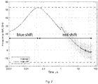
- Fig. 2 depicts a schematic frequency diagram of an optical frequency measurement result for a data burst using a normal preamble according to Fig.1 .
- the time shown on horizontal axis is logarithmic to emphasize fast effects at the beginning of the burst.
- the vertical axis represents the frequency drift from the median optical frequency.
- the dashed line in Fig. 2 depicts frequency excursion as measured at the optimum sampling point from "1" bits ("1 bit raw”) and its low-pass-filtered version ("1 bit LPF").
- the frequency drift has two domains, which are specific to the laser design.
- the first domain blue shift, starts from the beginning of the burst up to about 50 ns, with an increasing optical frequency. After this, the sign of frequency drift changes and the frequency decreases from 50 ns to the end of the burst. This is the red shift, caused by the thermal self-heating of the laser by the drive current. It can be seen from Fig. 2 , after the payload starts after 1 ⁇ s, there is a user data - dependent drift.
- the total burst length is 62.5 ⁇ s long.
- the repetition time is 125 ⁇ s.
- the excursion from the median optical frequency (corresponding to 0 on the vertical axis) to the point at which blue and red shift effects equalize (corresponding local maximum excursion at about 50 ns), is 53 GHz.
- the peak-to-peak spectral excursion with the normal preamble is -15 to +53 GHz, therefore 68 GHz in total.
- This frequency drift can, in the worst case, cause the optical signal to tune out of the optical receiver filter passband (40 GHz passband filter for 100 GHz grid spacing) leading to a degraded bit error rate, or even unrecoverable burst errors. Large frequency drifts can also result in leaking of the optical power to the neighbouring channels, resulting in interference and increased bit error rate in this neighbouring channel.
- Fig. 3 depicts a schematic amplitude envelope diagram of a predetermined preamble according to an embodiment of the invention.
- the predetermined preamble signal in Fig. 3 also has a duration of the first time t 1 , and comprises a repeated sequence composed of logical "1"(s) and logical "0"(s).
- the predetermined preamble may comprise a long repeated sequence of "1010".
- the composition of the predetermined preamble signal shall not be limited to the given example.
- the predetermined preamble may comprise a long repeated sequence of "1100" or "1000".
- the amplitude of the logical "1"s and logical "0"s in the predetermined preamble increases with the time.
- the current amplitude of the logical "1" in the predetermined preamble signal may increase linearly, logarithmically, or exponentially.
- the increasing manner of the current amplitude is not limited to the given examples.
- Other functions that are enabling a monotonic increase from A 4 to A 1 in a time interval of [0, t 4 ] are also possible.
- the current amplitude of the logical "0" in the predetermined preamble signal may also increase linearly, logarithmically, or exponentially.
- the increasing manner of the current amplitude is not limited to the given examples.
- Other functions that are enabling a monotonic increase from A 3 to A 2 in a time interval of [0, t 3 ] are also possible.
- the current amplitude of logical "1"s and logical "0"s in the predetermined preamble increases logarithmically.
- the current amplitude of logical "1"s and logical "0"s in the predetermined preamble increases exponentially.
- a t l 0 A 3 + A 2 ⁇ A 3 1 + q 1 ⁇ q 1 + q t l 0 / t 3 , where t l 0 is a time of occurrence of a logical "0" from the beginning of the predetermined preamble and q is an arbitrary constant and q ⁇ 0.
- the current amplitude of the logical "1" and the current amplitude of the logical “0” do not have to increase in the same manner.
- the current amplitude of the logical "1” may increase logarithmically, and the current amplitude of the logical "0” may increase exponentially.
- Other combinations of functions that are enabling a monotonic increase of the amplitude are also possible.
- Fig. 4 depicts a schematic amplitude diagram of a data burst using a preamble signal according to an embodiment of the invention.
- the preamble signal that is to be transmitted by the ONU is same as the predetermined preamble signal.
- the current amplitude of logical "1"s and logical "0"s in the predetermined preamble increases logarithmically to the nominal value.
- the preamble signal that is to be transmitted by the ONU may be different from the predetermined preamble signal.
- the fast blue shift can be mitigated.
- the current amplitude of logical "1" and the current amplitude of logical "0" increase from the same value.
- the current amplitude of logical "1” may be higher than the current amplitude of logical "0", i.e. A 4 >A 3 in Fig. 3 .
- the OLT is configured to receive the preamble signal with a duration of a first time t 1 from the ONU and receive a payload signal comprising user data after the preamble signal from the ONU.
- the OLT is further configured to determine a threshold for sampling the payload signal based on the current amplitude of the logical "1"s in the preamble signal no earlier than t 4 , and the current amplitude of logical "0"s in the preamble signal no earlier than t 3 .
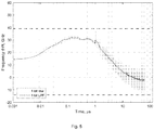
- Fig. 5 depicts a schematic frequency diagram of an optical frequency measurement result for a data burst using the preamble signal according to Fig.4 .
- the excursion is within the range from to -15 to +38 GHz, therefore 53 GHz. Comparing to Fig. 2 , this yields a reduction of 16 GHz in the peak-to-peak excursion. The maximum excursion does not happen at the point at which blue and red shift effects equalize, but at the beginning of the payload. The excursion from the median optical frequency to the point at which blue and red shift effects equalize is 31 GHz. Comparing to Fig. 2 , it is reduced by 22 GHZ.
- Fig. 5 the blue shift effect is mitigated and is no longer a dominant factor in the peak-to-peak excursion for the preamble signal specified in Fig. 4 . Instead, the user data-dependent drift is limiting peak-to-peak excursion reduction.
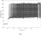
- Fig. 6 depicts a schematic amplitude diagram of a preamble signal according to another embodiment of the invention.
- Fig.6 there is provided another embodiment of the present invention that is easier to implement.
- the current amplitude of logical "1"s and logical "0"s in the predetermined preamble also increases logarithmically.
- the preamble signal that is to be transmitted by the ONU is different from the predetermined preamble signal.
- the preamble signal that is to be transmitted by the ONU comprises less logical "1"s than logical "0"s.
- the logical "1"s and the logical "0"s in the preamble signal have same current amplitude as those in the payload signal.
- the logical "1"s in the preamble signal have a current amplitude of the first value A 1 and the logical "0"s in the preamble signal have a current amplitude of the second value A 2 .
- some of the logical "1"s in the preamble signal that is to be transmitted by the ONU are replaced with "0"s in order to match the electrical energy delivered by the preamble signal from the beginning of the burst until the second time t 2 to the electrical energy delivered by the predetermined preamble from the beginning of the predetermined preamble signal to the second time t 2 , 0 ⁇ t 2 ⁇ t 1 .
- the OLT is further configured to determine a clock phase for the payload signal according to the logical "1"s comprised in the preamble signal.
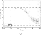
- Fig. 7 depicts a schematic frequency diagram of an optical frequency measurement result for a data burst using the preamble signal according to Fig. 6 .
- the result of the frequency drift measurement is very close to the result shown in Fig.5 for a data burst using the preamble signal according to Fig.4 .
- the excursion is within the range from to -15 to +38 GHz.
- the peak-to-peak excursion in Fig. 7 is 53 GHz. Comparing to Fig. 2 , this yields a reduction of 16 GHz in the peak-to-peak excursion.
- the possible embodiments of the present invention are not limited to the given examples. As long as the electrical energy delivered by the preamble signal that is to be transmitted by the ONU from a beginning of the preamble signal to the second time t 2 is less than an electrical energy delivered by the normal preamble signal from a beginning of the normal preamble signal to the second time t 2 , 0 ⁇ t 2 ⁇ t 1 , the blue shift effect can be mitigated.
Landscapes
- Physics & Mathematics (AREA)
- Electromagnetism (AREA)
- Engineering & Computer Science (AREA)
- Computer Networks & Wireless Communication (AREA)
- Signal Processing (AREA)
- Optics & Photonics (AREA)
- Optical Communication System (AREA)
Abstract
Description
- The invention relates to communication technology, in particular to burst data transmission in an optical communication system.
- Time- and wavelength-division multiplexed passive optical network (TWDM-PON) is the solution of choice for the next-generation passive optical network stage 2 (NG-PON2) systems. TWDM-PON is based on two multiplexing aspects: a) time-domain multiplexing of optical bursts from multiple transmitters, and b) wavelength division multiplexing allowing stacking multiple time division multiplexed sub- passive optical networks (PON) in wavelength domain.
- Due to aspect a), the transmitter in a TWDM-PON system is only active for the duration of the burst transmission. Due to b) the system requires optical filters (e.g., 40 GHz passband filter for 100 GHz grid spacing) to separate the traffic arriving at different wavelength from multiple optical network units (ONU) over the feeder fiber section to individual optical line terminal (OLT) receivers.
- A typical ONU transmitter employs a distributed feedback (DFB) laser as the optical transmitter. One of the fundamental properties of the DFB laser is that the optical emission frequency of such laser depends on the device temperature. Due to aforementioned time-multiplexing aspect, the data transmission is performed in bursts. When the transmitter becomes active, the drive current with non-zero mean is applied to the transmitter laser, which in turn leads to heat dissipation on the internal resistance of the device. This results in heating of the laser chip by its own drive current, so-called self-heating, which continuously alters the optical emission frequency of the laser during the burst emission, until thermal equilibrium is achieved. When no burst is being transmitted, the laser is switched off, the extra heat is dissipated and the laser is cooling again. Therefore, a typical burst mode operation consists of a repetition of the laser operating in on and off state, leading to a repeated frequency drift behaviour.
- The frequency drift has two domains. The first domain is the fast blue shift, starting from the beginning of the burst with an increasing optical frequency. The second domain is the slow red shift, with a decreasing frequency to the end of the burst.
- It is known that the laser self-heating-induced slow red shift can be mitigated by use of an on-chip resistor to quickly heat up the laser diode if no burst is emitted in order to keep the chip temperature constant. One possible implementation of this mitigation is the so-called counter-heating. This means that the heater is switched on when the laser is not emitting a burst and switched off when the laser emits a burst. In this way the laser temperature is intended to be kept constant all the time and thus no significant wavelength drift is observed. However thermal drift compensation using an on-chip resistor (or similar techniques relying on thermal effects) acts on timescales comparable to the repetition time of the burst and therefore are unable to compensate rapid drift effects, in particular the fast blue shift effect. Therefore, up to now, no mitigation strategy was proposed.
- G. Simon et al., "Focus on Time-Dependent Wavelength Drift of DMLs Under Burst-Mode Operation for NG-PON2," in Journal of Lightwave Technology, vol. 34, no. 13, pp. 3148-3154, 2016 discusses instead two drift avoidance strategies, whose aim is to reduce the system impact of the frequency drift, however this does not mitigate the actual effect. One proposal is to increase the channel spacing from 100 GHz to 200 GHz, which has the drawback of reduced spectral efficiency and would reduce the number of usable WDM channels from 8 to 4. The other proposal is to send padding data ahead of the preamble to warm up the laser and reach the in-band frequency during the padding, which limits the usable traffic drastically, especially for short bursts.
- An object of the invention is to mitigate the blue shift effect and thereby reduce the total frequency excursion.
- The object of the invention is achieved by the methods and apparatus in the claims.
- According to one aspect of the invention, there is provided a method of transmitting burst data in an optical network unit, comprising steps of: transmitting a preamble signal with a duration of a first time t1 to an optical line terminal; transmitting a payload signal comprising user data after the preamble signal to the optical line terminal; wherein, logical "1"s in the payload signal have a current amplitude of a first value A1, and logical "0"s in the payload signal have a current amplitude of a second value A2, A2 < A1; wherein, an electrical energy delivered by the preamble signal from a beginning of the preamble signal to a second time t2 is less than an electrical energy delivered by a normal preamble signal from a beginning of the predetermined preamble signal to the second time t2, 0<t2 ≤ t1; the normal preamble signal having a duration of the first time t1, comprising a repeated sequence composed of logical "1 "(s) and logical "0"(s); wherein, the logical "1" and logical "0" in the normal preamble signal have same current amplitude as those in the payload signal.
- In a preferred embodiment, the electrical energy delivered by the preamble signal from a beginning of the preamble signal to the second time t2 is corresponding to an electrical energy delivered by a predetermined preamble signal from a beginning of the predetermined preamble signal to the second time t2, the predetermined preamble signal having a duration of the first time t1, comprising a repeated sequence composed of logical "1 "(s) and logical "0"(s); a current amplitude of the logical "0" in the predetermined preamble signal increasing from a third value A3 at the beginning of the predetermined preamble signal to the second value A2 at a third time t3 and being constant at the second value A2 after the third time t3, and a current amplitude of the logical "1" in the predetermined preamble signal increasing from a fourth value A4 at the beginning of the predetermined preamble signal to the first value A1 at a fourth time t4 and being constant at the first value A1 after the fourth time t4, wherein, t3≤t4≤ t1, A3≤ A2, for A4< A1, and A3< A2, for A4= A1.
- In a preferred embodiment, the current amplitude of the logical "1" in the predetermined preamble signal increases according to a function:

- In a preferred embodiment, the current amplitude of the logical "0" in the predetermined preamble signal increases according to a function:

- In a preferred embodiment, the current amplitude of the logical "1" in the predetermined preamble signal increases according to a function;

- In a preferred embodiment, the current amplitude of the logical "0" in the predetermined preamble signal increases according to the function:

- In a preferred embodiment, wherein, A3= A4.
- In a preferred embodiment, the repeated sequence comprised in the predetermined preamble signal is "10".
- In a preferred embodiment, the preamble signal is same as the predetermined preamble signal.
- In a preferred embodiment, the preamble signal comprises less logical "1"s than logical "0"s, where the logical "1"s in the preamble signal have a current amplitude of the first value A1 and the logical "0"s in the preamble signal have a current amplitude of the second value A2.
- According another aspect of the invention, there is provided a method of receiving burst data in an optical line terminal, comprising steps of: receiving a preamble signal with a duration of a first time t1 from an optical network unit; receiving a payload signal comprising user data after the preamble signal from the optical network unit; wherein, an electrical energy delivered by the preamble signal from a beginning of the preamble signal to a second time t2 is less than an electrical energy delivered by a normal preamble signal from a beginning of the predetermined preamble signal to the second time t2, 0<t2 ≤ t1, the normal preamble signal comprising a repeated sequence composed of logical "1 "(s) and logical "0"(s); wherein, the logical "1" and logical "0" in the normal preamble signal have same current amplitude as those in the payload signal.
- In a preferred embodiment, the electrical energy delivered by the preamble signal from a beginning of the preamble signal to a second time t2 is corresponding to an electrical energy delivered by a predetermined preamble signal from a beginning of the predetermined preamble signal to the second time t2, 0<t2 ≤ t1, the predetermined preamble signal having a duration of the first time t1, comprising a repeated sequence composed of logical "1"(s) and logical "0"(s); a current amplitude of the logical "0" in the predetermined preamble signal increasing from a third value A3 at the beginning of the predetermined preamble signal to the second value A2 at a third time t3 and being constant at the second value A2 after the third time and a current amplitude of the logical "1" in the predetermined preamble signal increasing from a fourth value A4 at the beginning of the predetermined preamble signal to the first value A1 at a fourth time t4 and being constant at the first value A1 after the fourth time t4, wherein, t3<t4≤ t1, A3≤ A2, for A4< A1 and A3< A2, for A4= A1. the method further comprising a step of: determining a threshold for sampling the payload signal based on the current amplitude of the logical "1"s in the preamble signal no earlier than t4 and the current amplitude of logical "0"s in the preamble signal no earlier than t3.
- In a preferred embodiment, the method further comprising a step of: determining a clock phase for the payload signal according to the logical "1"s comprised in the preamble signal.
- According another aspect of the invention, there is provided an optical network unit, configured to: transmit a preamble signal with a duration of a first time t1 to an optical line terminal; transmit a payload signal comprising user data after the preamble signal to the optical line terminal; wherein, logical "1"s in the payload signal have a current amplitude of a first value A1, and logical "0"s in the payload signal have a current amplitude of a second value A2, A2 < A1; wherein, an electrical energy delivered by the preamble signal from a beginning of the preamble signal to a second time t2 is less than an electrical energy delivered by a normal preamble signal from a beginning of the predetermined preamble signal to the second time t2, 0<t2 ≤ t1; the normal preamble signal having a duration of the first time t1, comprising a repeated sequence composed of logical "1"(s) and logical "0"(s); wherein, the logical "1" and logical "0" in the normal preamble signal have same current amplitude as those in the payload signal.
- According another aspect of the invention, there is provided an optical line terminal, configured to: receive a preamble signal with a duration of a first time t1 from an optical network unit; receive a payload signal comprising user data after the preamble signal from the optical network unit; wherein, an electrical energy delivered by the preamble signal from a beginning of the preamble signal to a second time t2 is less than an electrical energy delivered by a normal preamble signal from a beginning of the predetermined preamble signal to the second time t2, 0<t2 ≤ t1, the normal preamble signal comprising a repeated sequence composed of logical "1"(s) and logical "0"(s); wherein, the logical "1" and logical "0" in the normal preamble signal have same current amplitude as those in the payload signal.
- According to the present invention, the fast blue shift is mitigated, and the frequency drift is reduced. Therefore, there is no need to increase channel spacing or pad before preamble to reduce the impact of the frequency drift on the system. The resource in the system may be used more efficiently. The traffic that can be transmitted in a TWDM-PON system may be increased.
- The features and advantages of the invention will be more completely understood by appreciating the following detailed description of preferred embodiments with reference to the figures, wherein
-
Fig. 1 depicts a schematic amplitude diagram of a data burst using a normal preamble; -
Fig. 2 depicts a schematic frequency diagram of an optical frequency measurement result for a data burst using a normal preamble according toFig.1 ; -
Fig. 3 depicts a schematic envelope amplitude diagram of a data burst using a predetermined preamble according to an embodiment of the invention; -
Fig. 4 depicts a schematic amplitude diagram of a data burst using a preamble signal according to an embodiment of the invention; -
Fig. 5 depicts a schematic frequency diagram of an optical frequency measurement result for a data burst using the preamble signal according toFig.4 ; -
Fig. 6 depicts a schematic amplitude diagram of a preamble signal according to another embodiment of the invention; -
Fig. 7 depicts a schematic frequency diagram of an optical frequency measurement result for a data burst using the preamble signal according toFig. 6 . - Exemplary embodiments of the present application are described herein in detail and shown by way of example in the drawings. It should be understood that, although specific exemplary embodiments are discussed herein there is no intent to limit the scope of the invention to such embodiments. To the contrary, it should be understood that the exemplary embodiments discussed herein are for illustrative purposes, and that modified and alternative embodiments may be implemented without departing from the scope of the invention. Similarly, specific structural and functional details disclosed herein are merely representative for purposes of describing the exemplary embodiments. The invention described herein, however, may be embodied in many alternate forms and should not be construed as limited to only the embodiments set forth herein.
- Normally, an ONU in the TWDM-PON architecture is configured to transmit a preamble signal with a duration of a first time t1 to an OLT; and transmit a payload signal comprising user data after the preamble signal to the OLT.
-
Fig. 1 depicts a schematic amplitude diagram of a data burst using a normal preamble. - Typically a normal preamble signal consists of a repeated sequence composed of logical "1"(s) and logical "0"(s); wherein, the logical "1" and logical "0" in the normal preamble signal have same current amplitude as those in the payload signal. In the example shown in
Fig. 1 , the logical "1"s in the normal preamble signal and the payload signal have a current amplitude of a first value A1, and logical "0"s in the normal preamble signal and the payload signal have a current amplitude of a second value A2, A2 < A1. The normal preamble starts with a nominal and constant amplitude of "1"s and keeps this amplitude constant during the entire burst (rectangular shape). Although the voltage amplitude is shown in the figures, a skilled person shall understand, the voltage amplitude in this measurement is linearly proportional to current amplitude. In the following of the description, the voltage amplitude in the figures may be described as current amplitude. - The preamble signal does not contain any user data. Its purpose is to assist locking of the burst-mode clock recovery to the received clock and to allow a measurement of the burst amplitude to set the data decision threshold at the OLT side.
- In
Fig. 1 , the normal preamble of the signal has a duration of 1 µs. The payload signal begins after 1 µs. The normal preamble comprises a long repeated sequence of "1010". A skilled person shall understand, the duration and the composition of the normal preamble shall not be limited to the given example. In another embodiment, the normal preamble may comprise a long repeated sequence of "1100" or "1000".Fig. 2 depicts a schematic frequency diagram of an optical frequency measurement result for a data burst using a normal preamble according toFig.1 . - As shown in
Fig.2 , the time shown on horizontal axis is logarithmic to emphasize fast effects at the beginning of the burst. The vertical axis represents the frequency drift from the median optical frequency. The dashed line inFig. 2 depicts frequency excursion as measured at the optimum sampling point from "1" bits ("1 bit raw") and its low-pass-filtered version ("1 bit LPF"). - As shown in
Fig. 2 , the frequency drift has two domains, which are specific to the laser design. The first domain, blue shift, starts from the beginning of the burst up to about 50 ns, with an increasing optical frequency. After this, the sign of frequency drift changes and the frequency decreases from 50 ns to the end of the burst. This is the red shift, caused by the thermal self-heating of the laser by the drive current. It can be seen fromFig. 2 , after the payload starts after 1 µs, there is a user data - dependent drift. - In the example shown in
Fig.2 , the total burst length is 62.5 µs long. The repetition time is 125 µs. The excursion from the median optical frequency (corresponding to 0 on the vertical axis) to the point at which blue and red shift effects equalize (corresponding local maximum excursion at about 50 ns), is 53 GHz. The peak-to-peak spectral excursion with the normal preamble is -15 to +53 GHz, therefore 68 GHz in total. - This frequency drift can, in the worst case, cause the optical signal to tune out of the optical receiver filter passband (40 GHz passband filter for 100 GHz grid spacing) leading to a degraded bit error rate, or even unrecoverable burst errors. Large frequency drifts can also result in leaking of the optical power to the neighbouring channels, resulting in interference and increased bit error rate in this neighbouring channel.
-
Fig. 3 depicts a schematic amplitude envelope diagram of a predetermined preamble according to an embodiment of the invention. - Similar to the normal preamble shown in
Fig 1 , the predetermined preamble signal inFig. 3 also has a duration of the first time t1, and comprises a repeated sequence composed of logical "1"(s) and logical "0"(s). The predetermined preamble may comprise a long repeated sequence of "1010". A skilled person shall understand, the composition of the predetermined preamble signal shall not be limited to the given example. In another embodiment, the predetermined preamble may comprise a long repeated sequence of "1100" or "1000". - However, the amplitude of the logical "1"s and logical "0"s in the predetermined preamble increases with the time.
- As shown in
Fig. 3 , the current amplitude of the logical "0" in the predetermined preamble signal increases from a third value A3 at the beginning of the predetermined preamble signal to the second value A2 at a third time t3 and being constant at the second value A2 after the third time and the current amplitude of the logical "1" in the predetermined preamble signal increases from a fourth value A4 at the beginning of the predetermined preamble signal to the first value A1 at a fourth time t4 and being constant at the first value A1 after the fourth time t4, wherein, t3≤t4≤ t1, A3≤ A2, for A4< A1, and A3< A2, for A4= A1. - In an embodiment of the invention, the current amplitude of the logical "1" in the predetermined preamble signal may increase linearly, logarithmically, or exponentially. The skilled person shall understand, the increasing manner of the current amplitude is not limited to the given examples. Other functions that are enabling a monotonic increase from A4 to A1 in a time interval of [0, t4] are also possible.
- Similarly, the current amplitude of the logical "0" in the predetermined preamble signal may also increase linearly, logarithmically, or exponentially. The skilled person shall understand, the increasing manner of the current amplitude is not limited to the given examples. Other functions that are enabling a monotonic increase from A3 to A2 in a time interval of [0, t3] are also possible.
- In one embodiment, the current amplitude of logical "1"s and logical "0"s in the predetermined preamble increases logarithmically.
- Specifically, the current amplitude of the logical "1" in the predetermined preamble signal increases according to a function:

- The current amplitude of the logical "0" in the predetermined preamble signal increases according to a function:

- In another embodiment of the present invention, the current amplitude of logical "1"s and logical "0"s in the predetermined preamble increases exponentially.
- Specifically, the current amplitude of the logical "1" in the predetermined preamble signal may increase according to a function:

- The current amplitude of the logical "0" in the predetermined preamble signal increases according to the function:

- The skilled person shall understand, the current amplitude of the logical "1" and the current amplitude of the logical "0" do not have to increase in the same manner. In one embodiment, the current amplitude of the logical "1" may increase logarithmically, and the current amplitude of the logical "0" may increase exponentially. Other combinations of functions that are enabling a monotonic increase of the amplitude are also possible.
-
Fig. 4 depicts a schematic amplitude diagram of a data burst using a preamble signal according to an embodiment of the invention. - In the embodiment shown in
Fig. 4 , the preamble signal that is to be transmitted by the ONU is same as the predetermined preamble signal. The current amplitude of logical "1"s and logical "0"s in the predetermined preamble increases logarithmically to the nominal value. In another embodiment, the preamble signal that is to be transmitted by the ONU may be different from the predetermined preamble signal. As long as the electrical energy delivered by the preamble signal that is transmitted by the ONU from a beginning of the preamble signal to a second time t2 is corresponding to an electrical energy delivered by the predetermined preamble signal from a beginning of the predetermined preamble signal to the second time t2, 0<t2 ≤ t1, the fast blue shift can be mitigated. - In the embodiment shown in
Fig, 4 , the current amplitude of logical "1" and the current amplitude of logical "0" increase from the same value. At the beginning of the preamble signal, the current amplitude of logical "1" and the current amplitude of logical "0" are the same, i.e. A3 = A4 inFig. 3 . The skilled person should understand, in another embodiment of the invention, at the beginning of the preamble signal, the current amplitude of logical "1" may be higher than the current amplitude of logical "0", i.e. A4>A3 inFig. 3 . - The OLT is configured to receive the preamble signal with a duration of a first time t1 from the ONU and receive a payload signal comprising user data after the preamble signal from the ONU.
- According to an embodiment of the invention, the OLT is further configured to determine a threshold for sampling the payload signal based on the current amplitude of the logical "1"s in the preamble signal no earlier than t4, and the current amplitude of logical "0"s in the preamble signal no earlier than t3.
-
Fig. 5 depicts a schematic frequency diagram of an optical frequency measurement result for a data burst using the preamble signal according toFig.4 . - The excursion is within the range from to -15 to +38 GHz, therefore 53 GHz. Comparing to
Fig. 2 , this yields a reduction of 16 GHz in the peak-to-peak excursion. The maximum excursion does not happen at the point at which blue and red shift effects equalize, but at the beginning of the payload. The excursion from the median optical frequency to the point at which blue and red shift effects equalize is 31 GHz. Comparing toFig. 2 , it is reduced by 22 GHZ. - According to
Fig. 5 , the blue shift effect is mitigated and is no longer a dominant factor in the peak-to-peak excursion for the preamble signal specified inFig. 4 . Instead, the user data-dependent drift is limiting peak-to-peak excursion reduction. -
Fig. 6 depicts a schematic amplitude diagram of a preamble signal according to another embodiment of the invention. - According to
Fig.6 , there is provided another embodiment of the present invention that is easier to implement. - Similar to the embodiment shown in
Fig.4 , in the embodiment shown inFig.6 , the current amplitude of logical "1"s and logical "0"s in the predetermined preamble also increases logarithmically. However, according to the embodiment shown inFig. 6 , the preamble signal that is to be transmitted by the ONU is different from the predetermined preamble signal. - In the embodiment shown in
Fig. 6 , the preamble signal that is to be transmitted by the ONU comprises less logical "1"s than logical "0"s. Throughout the whole duration of the preamble signal that is to be transmitted by the ONU, the logical "1"s and the logical "0"s in the preamble signal have same current amplitude as those in the payload signal. Specifically, the logical "1"s in the preamble signal have a current amplitude of the first value A1 and the logical "0"s in the preamble signal have a current amplitude of the second value A2. - Specifically, some of the logical "1"s in the preamble signal that is to be transmitted by the ONU are replaced with "0"s in order to match the electrical energy delivered by the preamble signal from the beginning of the burst until the second time t2 to the electrical energy delivered by the predetermined preamble from the beginning of the predetermined preamble signal to the second time t2, 0<t2 ≤ t1.
- According to the embodiment shown in
Fig. 6 , the OLT is further configured to determine a clock phase for the payload signal according to the logical "1"s comprised in the preamble signal. -
Fig. 7 depicts a schematic frequency diagram of an optical frequency measurement result for a data burst using the preamble signal according toFig. 6 . - As shown in
Fig. 7 , the result of the frequency drift measurement is very close to the result shown inFig.5 for a data burst using the preamble signal according toFig.4 . The excursion is within the range from to -15 to +38 GHz. The peak-to-peak excursion inFig. 7 is 53 GHz. Comparing toFig. 2 , this yields a reduction of 16 GHz in the peak-to-peak excursion. - A skilled person should understand, the possible embodiments of the present invention are not limited to the given examples. As long as the electrical energy delivered by the preamble signal that is to be transmitted by the ONU from a beginning of the preamble signal to the second time t2 is less than an electrical energy delivered by the normal preamble signal from a beginning of the normal preamble signal to the second time t2, 0<t2 ≤ t1, the blue shift effect can be mitigated.
Claims (15)
- A method of transmitting burst data in an optical network unit, comprising steps of:transmitting a preamble signal with a duration of a first time t1 to an optical line terminal;transmitting a payload signal comprising user data after the preamble signal to the optical line terminal; wherein, logical "1"s in the payload signal have a current amplitude of a first value A1, and logical "0"s in the payload signal have a current amplitude of a second value A2, A2 < A1;wherein, an electrical energy delivered by the preamble signal from a beginning of the preamble signal to a second time t2 is less than an electrical energy delivered by a normal preamble signal from a beginning of the predetermined preamble signal to the second time t2, 0<t2 ≤ t1;the normal preamble signal having a duration of the first time t1, comprising a repeated sequence composed of logical "1"(s) and logical "0"(s); wherein, the logical "1" and logical "0" in the normal preamble signal have same current amplitude as those in the payload signal.
- A method according to claim 1, wherein, the electrical energy delivered by the preamble signal from a beginning of the preamble signal to the second time t2 is corresponding to an electrical energy delivered by a predetermined preamble signal from a beginning of the predetermined preamble signal to the second time t2,
the predetermined preamble signal having a duration of the first time t1, comprising a repeated sequence composed of logical "1"(s) and logical "0"(s); a current amplitude of the logical "0" in the predetermined preamble signal increasing from a third value A3 at the beginning of the predetermined preamble signal to the second value A2 at a third time t3 and being constant at the second value A2 after the third time and a current amplitude of the logical "1" in the predetermined preamble signal increasing from a fourth value A4 at the beginning of the predetermined preamble signal to the first value A1 at a fourth time t4 and being constant at the first value A1 after the fourth time t4, wherein, t3≤t4≤ t1, A3≤ A2, for A4< A1, and A3< A2, for A4= A1. - A method according to claim 2, wherein, the current amplitude of the logical "1" in the predetermined preamble signal increases according to a function:

- A method according to claim 2, the current amplitude of the logical "0" in the predetermined preamble signal increases according to a function:

- A method according to claim 2, the current amplitude of the logical "1" in the predetermined preamble signal increases according to a function:

- A method according to claim 2, the current amplitude of the logical "0" in the predetermined preamble signal increases according to the function:

- A method according to claim 2, wherein, A3 = A4.
- A method according to claim 1, wherein, the repeated sequence comprised in the predetermined preamble signal is "10".
- A method according to any one of the claims 1-8, wherein, the preamble signal is same as the predetermined preamble signal.
- A method according to any one of the claims 1-8, wherein, the preamble signal comprises less logical "1"s than logical "0"s, where the logical "1"s in the preamble signal have a current amplitude of the first value A1 and the logical "0"s in the preamble signal have a current amplitude of the second value A2.
- A method of receiving burst data in an optical line terminal, comprising steps of:receiving a preamble signal with a duration of a first time t1 from an optical network unit;receiving a payload signal comprising user data after the preamble signal from the optical network unit;wherein, an electrical energy delivered by the preamble signal from a beginning of the preamble signal to a second time t2 is less than an electrical energy delivered by a normal preamble signal from a beginning of the predetermined preamble signal to the second time t2, 0<t2 ≤ t1,the normal preamble signal comprising a repeated sequence composed of logical "1"(s) and logical "0"(s); wherein, the logical "1" and logical "0" in the normal preamble signal have same current amplitude as those in the payload signal.
- A method according to claim 11, wherein, the electrical energy delivered by the preamble signal from a beginning of the preamble signal to a second time t2 is corresponding to an electrical energy delivered by a predetermined preamble signal from a beginning of the predetermined preamble signal to the second time t2, 0<t2 ≤ t1,
the predetermined preamble signal having a duration of the first time t1, comprising a repeated sequence composed of logical "1"(s) and logical "0"(s); a current amplitude of the logical "0" in the predetermined preamble signal increasing from a third value A3 at the beginning of the predetermined preamble signal to the second value A2 at a third time t3 and being constant at the second value A2 after the third time t3, and a current amplitude of the logical "1" in the predetermined preamble signal increasing from a fourth value A4 at the beginning of the predetermined preamble signal to the first value A1 at a fourth time t4 and being constant at the first value A1 after the fourth time t4, wherein, t3<t4≤ t1, A3≤ A2, for A4< A1 and A3< A2, for A4=A1,
the method further comprising a step of:determining a threshold for sampling the payload signal based on the current amplitude of the logical "1"s in the preamble signal no earlier than t4 and the current amplitude of logical "0"s in the preamble signal no earlier than t3. - A method according to claim 11, further comprising a step of:determining a clock phase for the payload signal according to the logical "1"s comprised in the preamble signal.
- An optical network unit, configured to:transmit a preamble signal with a duration of a first time t1 to an optical line terminal;transmit a payload signal comprising user data after the preamble signal to the optical line terminal; wherein, logical "1"s in the payload signal have a current amplitude of a first value A1, and logical "0"s in the payload signal have a current amplitude of a second value A2, A2 < A1;wherein, an electrical energy delivered by the preamble signal from a beginning of the preamble signal to a second time t2 is less than an electrical energy delivered by a normal preamble signal from a beginning of the predetermined preamble signal to the second time t2, 0<t2 ≤ t1;the normal preamble signal having a duration of the first time t1, comprising a repeated sequence composed of logical "1"(s) and logical "0"(s); wherein, the logical "1" and logical "0" in the normal preamble signal have same current amplitude as those in the payload signal.
- An optical line terminal, configured to:receive a preamble signal with a duration of a first time t1 from an optical network unit;receive a payload signal comprising user data after the preamble signal from the optical network unit;wherein, an electrical energy delivered by the preamble signal from a beginning of the preamble signal to a second time t2 is less than an electrical energy delivered by a normal preamble signal from a beginning of the predetermined preamble signal to the second time t2, 0<t2 ≤ t1;the normal preamble signal comprising a repeated sequence composed of logical "1"(s) and logical "0"(s); wherein, the logical "1" and logical "0" in the normal preamble signal have same current amplitude as those in the payload signal.
Priority Applications (2)
| Application Number | Priority Date | Filing Date | Title |
|---|---|---|---|
| EP17164387.7A EP3382911A1 (en) | 2017-03-31 | 2017-03-31 | Methods and apparatus for transmitting and receiving burst data |
| PCT/EP2018/056549 WO2018177763A1 (en) | 2017-03-31 | 2018-03-15 | Methods and apparatus for transmitting and receiving burst data |
Applications Claiming Priority (1)
| Application Number | Priority Date | Filing Date | Title |
|---|---|---|---|
| EP17164387.7A EP3382911A1 (en) | 2017-03-31 | 2017-03-31 | Methods and apparatus for transmitting and receiving burst data |
Publications (1)
| Publication Number | Publication Date |
|---|---|
| EP3382911A1 true EP3382911A1 (en) | 2018-10-03 |
Family
ID=58548976
Family Applications (1)
| Application Number | Title | Priority Date | Filing Date |
|---|---|---|---|
| EP17164387.7A Withdrawn EP3382911A1 (en) | 2017-03-31 | 2017-03-31 | Methods and apparatus for transmitting and receiving burst data |
Country Status (2)
| Country | Link |
|---|---|
| EP (1) | EP3382911A1 (en) |
| WO (1) | WO2018177763A1 (en) |
Cited By (1)
| Publication number | Priority date | Publication date | Assignee | Title |
|---|---|---|---|---|
| CN109586791A (en) * | 2018-12-21 | 2019-04-05 | 西北工业大学 | A kind of visible light communication method and device |
Citations (2)
| Publication number | Priority date | Publication date | Assignee | Title |
|---|---|---|---|---|
| US20150063812A1 (en) * | 2013-08-27 | 2015-03-05 | Calix, Inc. | Compensator for wavelength drift due to variable laser injection current and temperature in a directly modulated burst mode laser |
| US20150381300A1 (en) * | 2014-06-30 | 2015-12-31 | Calix, Inc. | System and method of compensating for spectral excursion |
-
2017
- 2017-03-31 EP EP17164387.7A patent/EP3382911A1/en not_active Withdrawn
-
2018
- 2018-03-15 WO PCT/EP2018/056549 patent/WO2018177763A1/en not_active Ceased
Patent Citations (2)
| Publication number | Priority date | Publication date | Assignee | Title |
|---|---|---|---|---|
| US20150063812A1 (en) * | 2013-08-27 | 2015-03-05 | Calix, Inc. | Compensator for wavelength drift due to variable laser injection current and temperature in a directly modulated burst mode laser |
| US20150381300A1 (en) * | 2014-06-30 | 2015-12-31 | Calix, Inc. | System and method of compensating for spectral excursion |
Non-Patent Citations (2)
| Title |
|---|
| G. SIMON ET AL.: "Focus on Time-Dependent Wavelength Drift of DMLs Under Burst-Mode Operation for NG-PON2", JOURNAL OF LIGHTWAVE TECHNOLOGY, vol. 34, no. 13, 2016, pages 3148 - 3154, XP011615671, DOI: doi:10.1109/JLT.2016.2552719 |
| POEHLMANN WOLFGANG ET AL: "Wavelength drift of burst-mode DML for TWDM-PON [invited]", JOURNAL OF OPTICAL COMMUNICATIONS AND NETWORKING, INSTITUTE OF ELECTRICAL AND ELECTRONICS ENGINEERS, US, vol. 7, no. 1, 1 January 2015 (2015-01-01), XP011571352, ISSN: 1943-0620, [retrieved on 20150126], DOI: 10.1364/JOCN.7.000A44 * |
Cited By (2)
| Publication number | Priority date | Publication date | Assignee | Title |
|---|---|---|---|---|
| CN109586791A (en) * | 2018-12-21 | 2019-04-05 | 西北工业大学 | A kind of visible light communication method and device |
| CN109586791B (en) * | 2018-12-21 | 2021-08-17 | 国网吉林省电力有限公司信息通信公司 | Method and device for visible light communication |
Also Published As
| Publication number | Publication date |
|---|---|
| WO2018177763A1 (en) | 2018-10-04 |
Similar Documents
| Publication | Publication Date | Title |
|---|---|---|
| EP2283592B1 (en) | Method and apparatus for controlling the optical output power from a burst mode laser | |
| KR101310455B1 (en) | Wavelength division multiplexing passive optical network(wdm-pon) | |
| US8335428B2 (en) | Method and system for protection switching | |
| KR101532967B1 (en) | Wdm pon with non tunable legacy onus | |
| CN102577428B (en) | Method and apparatus for conditioning lasers in an optical network | |
| US9523867B2 (en) | Off quadrature biasing of Mach Zehnder modulator for improved OSNR performance | |
| US12526058B2 (en) | Optical power supply system, optical power supply method and power receiving optical communication apparatus | |
| CN112448758B (en) | Wavelength adjusting method and related equipment | |
| US20140233945A1 (en) | Wavelength division multiplexing optical transmitting apparatus and operating method of the same | |
| WO2019149993A1 (en) | Optical burst monitoring | |
| EP2999151B1 (en) | Method and communication control device for establishing a communication channel in a communication network | |
| US10644801B2 (en) | Proactive channel probing for wavelength switching in optical transmission systems | |
| Gatto et al. | Integration of QKD technologies in advanced optical networks | |
| Kowalczyk et al. | VLC link with LEDs used as both transmitters and photo-detectors | |
| WO2018177763A1 (en) | Methods and apparatus for transmitting and receiving burst data | |
| US20170187463A1 (en) | Delay-based nonlinear equalizer | |
| EP3662595B1 (en) | Optical transmitter operating burst mode and control method of optical transmitter operating burst mode | |
| US10419153B2 (en) | Optical transmitter and optical transmitting method | |
| Fabrega et al. | Experimental demonstration of elastic optical networking utilizing time-sliceable bitrate variable OFDM transceiver | |
| CN112602331B (en) | Transmitting and receiving method and device with preset frequency interval | |
| CN203554454U (en) | Passive optical network, optical link terminal (OLT) and optical module thereof | |
| Porto et al. | 10Gb/s low-cost directly modulated multi-electrode laser with suppressed thermal wavelength drift for burst-mode upstream transmission in TWDM-PONs | |
| Cano et al. | An OFDMA-PON with non-preselected independent ONU sources and centralized feedback wavelength control: Dimensioning and experimental results | |
| JPH0669884A (en) | Optical parallel transmitter | |
| Krehlik et al. | Laser driver with subthreshold laser bias and turn-on-delay compensation by prejittering of the modulating current |
Legal Events
| Date | Code | Title | Description |
|---|---|---|---|
| PUAI | Public reference made under article 153(3) epc to a published international application that has entered the european phase |
Free format text: ORIGINAL CODE: 0009012 |
|
| STAA | Information on the status of an ep patent application or granted ep patent |
Free format text: STATUS: THE APPLICATION HAS BEEN PUBLISHED |
|
| AK | Designated contracting states |
Kind code of ref document: A1 Designated state(s): AL AT BE BG CH CY CZ DE DK EE ES FI FR GB GR HR HU IE IS IT LI LT LU LV MC MK MT NL NO PL PT RO RS SE SI SK SM TR |
|
| AX | Request for extension of the european patent |
Extension state: BA ME |
|
| STAA | Information on the status of an ep patent application or granted ep patent |
Free format text: STATUS: REQUEST FOR EXAMINATION WAS MADE |
|
| 17P | Request for examination filed |
Effective date: 20190403 |
|
| RBV | Designated contracting states (corrected) |
Designated state(s): AL AT BE BG CH CY CZ DE DK EE ES FI FR GB GR HR HU IE IS IT LI LT LU LV MC MK MT NL NO PL PT RO RS SE SI SK SM TR |
|
| RAP1 | Party data changed (applicant data changed or rights of an application transferred) |
Owner name: NOKIA SOLUTIONS AND NETWORKS OY |
|
| STAA | Information on the status of an ep patent application or granted ep patent |
Free format text: STATUS: EXAMINATION IS IN PROGRESS |
|
| 17Q | First examination report despatched |
Effective date: 20210222 |
|
| STAA | Information on the status of an ep patent application or granted ep patent |
Free format text: STATUS: THE APPLICATION IS DEEMED TO BE WITHDRAWN |
|
| 18D | Application deemed to be withdrawn |
Effective date: 20210706 |