EP3382910A1 - Optical transceiver and method of operating an optical transceiver - Google Patents
Optical transceiver and method of operating an optical transceiver Download PDFInfo
- Publication number
- EP3382910A1 EP3382910A1 EP17164195.4A EP17164195A EP3382910A1 EP 3382910 A1 EP3382910 A1 EP 3382910A1 EP 17164195 A EP17164195 A EP 17164195A EP 3382910 A1 EP3382910 A1 EP 3382910A1
- Authority
- EP
- European Patent Office
- Prior art keywords
- optical
- signal
- frequency
- transceiver
- modulated
- Prior art date
- Legal status (The legal status is an assumption and is not a legal conclusion. Google has not performed a legal analysis and makes no representation as to the accuracy of the status listed.)
- Granted
Links
Images



Classifications
-
- H—ELECTRICITY
- H04—ELECTRIC COMMUNICATION TECHNIQUE
- H04B—TRANSMISSION
- H04B10/00—Transmission systems employing electromagnetic waves other than radio-waves, e.g. infrared, visible or ultraviolet light, or employing corpuscular radiation, e.g. quantum communication
- H04B10/40—Transceivers
-
- H—ELECTRICITY
- H04—ELECTRIC COMMUNICATION TECHNIQUE
- H04B—TRANSMISSION
- H04B10/00—Transmission systems employing electromagnetic waves other than radio-waves, e.g. infrared, visible or ultraviolet light, or employing corpuscular radiation, e.g. quantum communication
- H04B10/60—Receivers
- H04B10/61—Coherent receivers
- H04B10/614—Coherent receivers comprising one or more polarization beam splitters, e.g. polarization multiplexed [PolMux] X-PSK coherent receivers, polarization diversity heterodyne coherent receivers
-
- H—ELECTRICITY
- H04—ELECTRIC COMMUNICATION TECHNIQUE
- H04B—TRANSMISSION
- H04B10/00—Transmission systems employing electromagnetic waves other than radio-waves, e.g. infrared, visible or ultraviolet light, or employing corpuscular radiation, e.g. quantum communication
- H04B10/60—Receivers
- H04B10/61—Coherent receivers
- H04B10/64—Heterodyne, i.e. coherent receivers where, after the opto-electronic conversion, an electrical signal at an intermediate frequency [IF] is obtained
Definitions
- the disclosure relates to an optical transceiver and to a method of operating an optical transceiver.
- the disclosure further relates to an optical transmission system and to a method of operating an optical transmission system.
- Various embodiments provide an improved optical transceiver and an improved method of operating an optical transceiver, which do not suffer from one or more of the above-mentioned limitations and which enable to implement efficient optical transmission schemes.
- Some embodiments feature an optical transceiver comprising an optical transmitter having an optical modulator for modulating an optical carrier signal, a coherent optical receiver for demodulating data from a received data-modulated optical signal, and a laser source being connected to provide, at a first frequency, the optical carrier signal and an optical local oscillator signal, the coherent optical receiver being configured to demodulate data from said received data-modulated optical signal at a second carrier frequency, the second carrier frequency being shifted from said first frequency by a first frequency shift.
- this configuration requires only one laser source.
- said coherent receiver is configured to process modulated optical signals having a carrier frequency which is shifted with respect to said first frequency of said optical signal of said laser source by a first frequency shift, i.e. said modulated optical signals have been generated using said shifted carrier frequency.
- a coherent receiver configured to process modulated optical signals having a carrier frequency which is shifted with respect to said first frequency of said optical signal of said laser source (and of said local oscillator signal) by said frequency shift may also be denoted as " Kramers-Kronig coherent receiver” as proposed by Antonio Mecozzi, Cristian Antonelli , and Mark Shtaif, "Kramers-Kronig coherent receiver.”, Optica 3.11 (2016): 1220-1227 , which is incorporated by reference in its entirety as [reference 1]. This document is also available on the Internet, cf. http://dx.doi.org/10.1364/OPTICA.3.001220.
- a Kramers-Kronig (KK) processing scheme which may form part of one or more embodiments of the disclosure, is disclosed in chapter 3. and Fig. 2 of [reference 1].
- the subject-matter of [reference 1] and especially chapter 3. and Fig. 2 of [reference 1] are included in the present disclosure.
- Fig. 2b of [reference 1] discloses a KK scheme according to which a local oscillator signal ("LO") is added to a received information carrying signal (e.g., modulated signal) at the receiver using a frequency-selective coupler to avoid signal and LO loss. More specifically, said LO is added at a left edge of the modulated signal.
- LO local oscillator signal
- This implementation eliminates the need for an optical hybrid at the receiver, and requires the use of (only) a single photodiode.
- the KK scheme with the LO added at the receiver eliminates the need for balanced detection, whose implementation, especially at high baud rates, may become nontrivial.
- an optical power splitter may be provided which is connected to receive light from said laser source and to produce said optical carrier signal on one optical output thereof and to produce said optical local oscillator signal on another output thereof.
- both said optical carrier signal and said local oscillator signal for said coherent optical receiver may be derived from said optical signal of said laser source using the optical power splitter.
- said optical power splitter enables to divide the signal of the laser source into e.g. two portions with a predetermined optical power ratio.
- said coherent optical receiver is configured to process modulated optical signals having a carrier frequency which is shifted with respect to said first frequency of said optical signal of said laser source (and thus also with respect to the frequency of its local oscillator signal, which is derived from said optical signal of the laser source) by a first frequency shift.
- said coherent receiver comprises an input stage which is configured to receive said modulated optical signal and said local oscillator signal, and to add said local oscillator signalto said modulated optical signal.
- further processing such as e.g. a frequency downconversion in the optical domain and further demodulation processing, e.g. by applying an ASSB (asynchronous single side band) converter scheme as explained further below.
- ASSB asynchronous single side band
- said coherent receiver is configured to convert two output signals of said input stage from the optical domain to the electrical domain, wherein two electrical output signals are obtained, and to perform an analog-to-digital conversion of said two electrical output signals to obtain two digital signals.
- one photodiode and one ADC per output signal of said input stage may be provided for said conversion of said two electrical output signals to obtain said two digital signals.
- said coherent receiver comprises a signal reconstruction stage configured to transform said two digital signals into output signals characterizing a phase and an amplitude of two polarizations of said modulated optical signal.
- a signal reconstruction stage configured to transform said two digital signals into output signals characterizing a phase and an amplitude of two polarizations of said modulated optical signal.
- said optical modulator is a polarisation division multiplexing, PDM, I/Q modulator configured to provide a first and a second polarization, i.e. two orthogonal polarizations, of said optical carrier signal and to modulate phase and amplitude (or I/Q components, respectively) of said two orthogonal polarizations, whereby DP-QPSK modulated signals may be provided.
- PDM polarisation division multiplexing
- I/Q modulator configured to provide a first and a second polarization, i.e. two orthogonal polarizations, of said optical carrier signal and to modulate phase and amplitude (or I/Q components, respectively) of said two orthogonal polarizations, whereby DP-QPSK modulated signals may be provided.
- such PDM I/Q modulator may comprise at its input an optical splitter to provide two optical input signals, two IQ Mach-Zehnder-modulators for effecting IQ modulation to said two optical input signals, a polarization rotator to effect a change of polarization of an output signal of one of said two IQ Mach-Zehnder-modulators, e.g. from TE (transversal electric) state to TM (transversal magnetic) state, and a polarization beam combiner to combine the optical signals of different (TE, TM) polarization states, thus delivering e.g. a PDM I/Q modulated signal or DP-QPSK modulated signal, respectively.
- TE transversal electric
- TM transversal magnetic
- said first frequency is shifted from said second frequency by, at least, about half of a baud rate of said optical receiver.
- the first frequency shift corresponds to about half of a baud rate of said optical receiver.
- said first frequency is shifted from said second frequency by, at least, about half of a baud rate of said optical modulator.
- a symbol rate or baud rate, respectively, at the optical transmitter may be different from a symbol rate or baud rate, respectively, at the optical receiver.
- said optical transceiver may use a first frequency which is shifted from said second frequency by, at least, about half of a baud rate of said optical receiver.
- said optical transceiver may use a first frequency which is shifted from said second frequency by, at least, about half of a baud rate of said optical modulator.
- said optical transceiver uses an optical power splitter which is connected to receive light from said laser source and to produce said optical carrier signal on one optical output thereof and to produce said optical local oscillator signal on another output thereof.
- said first transceiver is configured to provide said modulated optical output signal with a first symbol rate, wherein said second frequency shift ranges between about 40 percent of a symbol rate of said first modulated optical output signal and about 65 percent of said symbol rate of said first modulated optical output signal.
- said second transceiver is configured to provide said modulated optical output signal with a second symbol rate.
- said second symbol rate is equal to the first symbol rate.
- Other embodiments may also provide for different first and second symbol rates.
- a WDM (wavelength division multiplexed) system e.g. a point-to-point WDM system, wherein e.g. n many transmission signals of a same transmission direction may be transmitted within a same optical fiber.
- each WDM carrier may be used to transmit e.g. a DP-QPSK modulated signal.
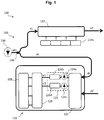
- FIG. 1 schematically depicts a block diagram of an optical transceiver 100 according to an embodiment.
- the optical transceiver 100 comprises an optical transmitter 110 with an optical modulator 112, preferably optical data modulator, for modulating an optical carrier signal s1 to obtain a data-modulated optical output signal s2, which may be transmitted via an optical transmission channel, e.g. including a series of one or more optical fibers (not shown in Fig. 1 ), to an optical receiver.
- an optical transmission channel e.g. including a series of one or more optical fibers (not shown in Fig. 1 .
- the optical transceiver 100 further comprises a coherent optical receiver 120, also denoted as "Kramers-Kronig coherent receiver” in the following, for demodulating data from a received data-modulated optical signal s5', which has a carrier frequency and/or bandwidth that may be close to the carrier frequency and/or bandwidth of the modulated optical output signal s2.
- the optical transceiver 100 further comprises a laser source 130, e.g. a conventional semiconductor laser, with or without an external cavity, that provides a continuous optical signal s01 at a first frequency.
- said first frequency may correspond with a wavelength within the optical C-band (1530 nm to 1565 nm) or optical L-band (1565 nm to 1625 nm).
- other frequencies are also possible for the continuous optical signal s01.
- the optical transceiver 100 is configured to produce said optical carrier signal s1 for the optical modulator 112 and an optical local oscillator signal s6 for said Kramers-Kronig coherent receiver 120 from said optical signal s01 of said laser source 130.
- an optical power splitter 140 splits the signal s01 from the laser source 130, e.g. power splits the signal s01, to produce the signal s1 for the optical modulator 112 of the transmitter 110 and the signal s6 for the optical interface of the coherent receiver 120.
- the optical transceiver 100 comprises a single laser source 130, which is shared between the transmitter 110 and the receiver 120.
- the coherent receiver 120 is configured to process modulated optical signals s5' having a carrier frequency which is shifted with respect to said first frequency of said optical signal s01 of said laser source 130 (and thus also with respect to the frequency of its local oscillator signal s6) by a first frequency shift.
- such coherent receiver may also be denoted as “Kramers-Kronig coherent receiver”.
- the modulator 112 provides polarisation division multiplexing, PDM, an includes, e.g., in-phase (I) and quadrature-phase (Q) modulators configured to provide separate I and Q modulations of each of the two orthogonal polarizations (i.e., TE and TM state) of said optical carrier signal s1.
- Such modulation can be phase modulation or phase and amplitude modulation of said two orthogonal polarizations, whereby DP-QPSK or DP-quadrature amplitude modulation (QAM) modulated signals may be provided.
- the respectively polarized signals may be combined by a polarization beam combiner (not shown) to combine the optical signals of said different modulated (TE, TM) polarization states, thus delivering e.g. said PDM and I/Q modulated signal, e.g., as a specific example a DP-QPSK modulated signal, respectively, which is denoted by reference sign s2 in Figure 1 .
- electrical input signals to the PDM I/Q modulator 112 may be provided by DAC (digital-to-analog converter) or driver stages, only one of which is denoted in Fig. 1 with the reference sign 114a.
- a symbol rate used for said modulation may be denoted as "R".
- the Kramers-Kronig coherent receiver 120 of said optical transceiver 100 may be configured to receive and to process such PDM I/Q modulated signals, e.g., DP-QPSK or DP-QAM modulated signals, respectively, cf. reference sign s5'.
- PDM I/Q modulated signals e.g., DP-QPSK or DP-QAM modulated signals, respectively, cf. reference sign s5'.
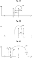
- Figure 3A schematically depicts a spectrum SS1 of an optical signal having a bandwidth BW1 according to an embodiment.
- said optical signal may comprise a bandwidth BW1 of about 32 GHz (gigahertz), and said optical signal may comprise a symbol rate of about 32 Gbaud (gigabaud).
- Reference sign f1 indicates the spectral representation of the optical signal s01 ( Fig. 1 ) of said laser source 130 or the optical carrier signal s1, whereas said spectrum SS1 ( Fig. 3A ) represents the modulated optical output signal s2 ( Fig. 1 ).
- Reference sign f2 indicates the frequency-shifted carrier signal of said modulated optical signals s5' the Kramers-Kronig coherent receiver 120 according to the embodiments is configured to process, and said first frequency shift between said carrier signals f1, f2 is indicated by reference sign ⁇ f1.
- said first frequency shift ⁇ f1 may be greater than about 40 percent of a symbol rate of said modulated optical signals s5' which ensures proper processing based on a Kramers-Kronig scheme. In the above example with a symbol rate of about 32 Gbaud, said first frequency shift ⁇ f1 may be greater than about 12.6 GHz.
- said first frequency shift ⁇ f1 may be greater than about 45 percent of a symbol rate of said modulated optical signals s5'.
- said first frequency shift ⁇ f1 may be greater than about 49 percent of a symbol rate of said modulated optical signals s5'.
- said first frequency shift ⁇ f1 may range between about 40 percent of a symbol rate of said modulated optical signals s5' and about 65 percent of said symbol rate of said modulated optical signals s5'.
- said first frequency shift ⁇ f1 may range between about 45 percent of a symbol rate of said modulated optical signals s5' and about 60 percent of said symbol rate of said modulated optical signals s5'.
- said first frequency shift ⁇ f1 may range between about 50 percent of a symbol rate of said modulated optical signals s5' and about 55 percent of said symbol rate of said modulated optical signals s5'. While this range enables an even improved signal reconstruction within the coherent receiver 120, it may only require comparatively moderate processing bandwidths for components of the coherent receiver 120.
- Figure 3C schematically depicts exemplary frequency shifts according to some embodiments and associated ranges. Note that a different scale of the frequency axis f' is used in Fig. 3C , as compared to Fig. 3A , for the sake of clarity. Fig. 3C also depicts the spectrum SS1 and its carrier frequency f1.
- Reference sign r1 exemplarily depicts a first frequency range associated with said first frequency shift ⁇ f1 as explained above with reference to Fig. 3A .
- said first frequency shift ⁇ f1 may range between about 40 percent of a symbol rate of said modulated optical signals s5' and about 65 percent of said symbol rate of said modulated optical signals s5', which corresponds with said first frequency range r1 of Fig. 3C .
- said first frequency shift ⁇ f1 may be chosen such that the frequency-shifted carrier signal f21 of said modulated optical signals s5' lies within the first frequency range r1.
- Exemplary first carrier signal c21 depicts an embodiment wherein the first frequency shift ⁇ f1 is chosen such that said carrier signal c21 is arranged substantially directly outside the bandwidth BW1 ( Fig. 3A ), i.e. in Fig. 3C outside a left (i.e. lower, on a frequency axis f') band edge of spectrum SS1.
- Exemplary second carrier signal c22 depicts an embodiment wherein the first frequency shift ⁇ f1 is chosen such that said second carrier signal c22 is arranged inside the bandwidth BW1 ( Fig. 3A ). While signal reconstruction may be inferior as compared to using said first carrier signal c21, the principle according to the embodiments may still be applied for this exemplary configuration.
- Exemplary third carrier signal c23 depicts an embodiment wherein the first frequency shift ⁇ f1 is chosen such that said third carrier signal c23 is arranged further outside the bandwidth BW1 ( Fig. 3A ) as compared to first carrier signal c21. This may account for non-zero roll-off factors of spectrum SS1, frequency uncertainties of the involved laser sources, and the like.
- Reference sign r2 exemplarily depicts a second frequency range associated with said first frequency shift ⁇ f1 as explained above with reference to Fig. 3A according to further embodiments.
- said second frequency range r2 is smaller than said first frequency range r1, but e.g. comprises said first carrier signal c21.
- the values of the carrier frequencies and the first frequency shift ⁇ f1 may also be chosen such that corresponding ranges r1', r2' for the first frequency shift ⁇ f1 are provided at a right (i.e., upper) band edge of spectrum SS1.
- the signal reconstruction stage 126 may perform the ASSB scheme as depicted by Fig. 3 of [reference 2], wherein for the term m MP t c , the second digital signal d2 (or a signal derived therefrom) is used.
- a first intermediate signal 1 + s 1 t c 1 is obtained.
- a spectrum of said first intermediate signal is1 is exemplarily depicted by Fig. 9C . As can be seen, it comprises an upper sideband RSB around frequency f int , a lower sideband LSB, and a constant component DC at frequency 0. Note that the spectrum of said first intermediate signal is1 as depicted by Fig. 9C corresponds with an electrical baseband range, as an example below e.g. 50 GHz, as opposed to the optical signal spectrum around e.g. about 194 THz as depicted by Fig. 9A, 9B . This is i.a. due to the envelope detection using the photodiode 124a as explained above.
- a filtering process is applied to the (spectrum of said) first intermediate signal is1, cf. Fig. 9C , which removes the lower sideband LSB and the constant component DC, and which leads to a filtered signal the spectrum of which is depicted by Fig. 9D .
- the upper sideband RSB around intermediate frequency f int is obtained.
- DSP digital signal processor
- the above-explained application of the ASSB scheme as depicted by Fig. 3 of [reference 2] may also be performed by said DSP 128, or by another calculating unit.
- Figure 10 schematically depicts a flow-chart of a method of operating the signal reconstruction stage 126 ( Fig. 8 ) according to a preferred embodiment.
- block 400 of Fig. 10 implements an ASSB converter as depicted by Fig. 3 of [reference 2], wherein the input signal u1 corresponds to term m MP t c , and wherein the output signal u2 corresponds to term 1 + s t c of Fig. 3 of [reference 2].
- An exemplary spectrum of the output signal u2 is depicted by Fig. 9C and has already been explained above.
- Subsequent block 402 applies a filtering process to output signal u2, wherein the lower sideband LSB ( Fig. 9C ) and the constant component DC is removed, which leads to signal u3, having a spectrum as depicted by Fig. 9D .
- signal u4 may be downsampled (decimation) in step 406, wherein a decimated signal u5 is obtained.
- the above-explained process illustrated by Fig. 10 may be performed by said DSP 128.
- an input stage 122 of the Kramers-Kronig coherent receiver 120 receives a modulated optical signal s5', and in step 252 said local oscillator signal s6 is added to said received modulated optical signal s5' to enable further processing of the so obtained sum signal.
- said digital signals d1, d2 as explained above with reference to figure 1 are obtained from said sum signal (step not shown in figure 6B ), and in subsequent step 254, said digital signals d1, d2 are transformed by said signal reconstruction stage 126 ( Fig. 1 ) into output signals characterising a phase and an amplitude of two polarisations of said modulated optical signal s5'.
- a demodulation based on said output signals of the signal reconstruction stage 126 may be done.
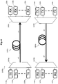
- FIG. 2 schematically depicts a block diagram of an optical transmission system 1000 according to an embodiment.
- the optical transmission system 1000 comprises two optical transceivers 100a, 100b, each of which may comprise a configuration and/or functionality at least similar to the one as explained above with reference to the optical transceiver 100 of Fig. 1 .
- the optical transmitters 110 with the optical modulators 112 and the Kramers-Kronig coherent receivers 120 may be identical regarding their configuration and/or functionality for both optical transceivers 100a, 100b.
- An optical output of the transmitter 110 of the first optical transceiver 100a is connected with an optical input of a Kramers-Kronig coherent receiver 120 of said second optical transceiver 100b via a first optical fiber link 1002a
- an optical output of the transmitter 110 of the second optical transceiver 100b is connected with an optical input of a Kramers-Kronig coherent receiver 120 of said first optical transceiver 100a via a second optical fiber link 1002b.
- the transceivers 100a, 100b may exchange optical signals such as the modulated optical output signals s2, s5 with each other.
- the correspondingly received optical signals are denoted with reference signs s2', s5'.
- Figure 7A schematically depicts a simplified flow-chart of a method of operating the optical transmission system 1000 of figure 4 according to an embodiment.
- the laser source 131 of said first optical transceiver 100a provides said first continuous optical signal s01.
- the laser source 132 of said second optical transceiver 100b provides said second continuous optical signal s02, a center frequency of which being different from the center frequency of said first continuous optical signal s01, the frequency difference being expressed by said second frequency shift ⁇ f2.
- the transceivers 100a, 100b may use the signals s01, s02 for transmitting optical signals and/or processing received optical signal of.
- steps 300, 310, 320 above may also be performed simultaneously to each other or in another sequence as explained above.
- step 324a the modulator 112 of said first optical transceiver 100a modulates said first optical carrier signal s1 with a first symbol rate, to obtain a first modulated optical output signal s2.
- step 324b the modulator 112 of said second optical transceiver 100b modulates said second optical carrier signal s4 with a second symbol rate, to obtain a second modulated optical output signal s5.
- said second symbol rate is equal to said first symbol rate.
- step 326a the first optical transceiver 100a transmits said first modulated optical output signal s2 via the first optical fiber link 1002a to the second optical transceiver 100b.
- step 326b the second optical transceiver 100b transmits said second modulated optical output signal s5 via the second optical fiber link 1002b to the first optical transceiver 100a
- one or more amplifiers may be provided within said optical fiber link 1002a and/or said optical fiber link 1002b.
- FIG. 4 schematically depicts a block diagram of an optical transmission system 1000a according to a further embodiment.
- the system 1000a may be considered as a point-to-point wavelength division multiplexed (WDM) system, as a plurality of wavelength channels (or frequency channels, respectively) are transmitted in the same fiber.
- WDM wavelength division multiplexed
- n many optical transceivers are provided at a first location, wherein the transmitters of said n many optical transceivers are denoted in Fig. 4 with reference signs 110a, 110b, ..., 110m, and wherein the optical receivers of said n many optical transceivers are denoted in Fig. 4 with reference signs 120a, 120b, ..., 120m.
- n many further transmitters 110n, 110o, ..., 110z and n many further receivers 120n, 120o, ..., 120z of Fig. 4 may be provided in the form of n many further optical transceivers of the type 100 as explained with reference to Fig. 1 .
- the transmitters 110a, 110b, ..., 110m are coupled to a first transmitter multiplexer 1004a, and the receivers 120n, 120o, ..., 120z are coupled to a first receiver multiplexer 1006a, wherein said multiplexers 1004a, 1006a are coupled by means of an optical fiber 1002c.
- This configuration e.g. enables the transmitter 110a to transmit (modulated) optical output signals s2 ( Fig. 2 ) to the receiver 120n, the transmitter 110b to transmit (modulated) optical output signals to the receiver 120o, and so on.
- the transmitters 110n, 110o, ..., 110z are coupled to a second transmitter multiplexer 1004b, and the receivers 120a, 120b, ..., 120m are coupled to a second receiver multiplexer 1006b, wherein said multiplexers 1004b, 1006b are coupled by means of an optical fiber 1002d.
- This configuration e.g. enables the transmitter 110n to transmit (modulated) optical output signals s5 ( Fig. 2 ) to the receiver 120a, the transmitter 110o to transmit (modulated) optical output signals to the receiver 120b, and so on.
- a resulting first WDM transmission signal in a first transmission direction is denoted with reference sign s7 in Fig. 4 .
- said first WDM transmission signal s7 is provided as signal s7' to the first receiver multiplexer 1006a.
- a resulting second WDM transmission signal in a second transmission direction is denoted with reference sign s8 in Fig. 4 .
- said second WDM transmission signal s8 is provided as signal s8' to the second receiver multiplexer 1006b.
- a first transceiver which comprises the transmitter 110a and the receiver 120a of Fig. 4 , comprises a laser source (not shown) providing a continuous optical signal at frequency f11
- a second transceiver which comprises the transmitter 110b and the receiver 120b, comprises a laser source (not shown) providing a continuous optical signal at frequency f12
- the channel spacing CS ( Fig. 5 ) characterizes a difference of neighbouring carrier frequencies f11, f12.
- said channel spacing CS is substantially constant for all transceivers.
- each of said n many further optical transceivers comprising the components 120n to 120z and 110n to 110z of Fig. 4 comprises a laser source a signal frequency of which is shifted with respect to the signal frequency of the other further optical transceivers by said predetermined channel spacing CS to enable said WDM transmission scheme.
- This is exemplarily depicted for six carrier frequencies f21 to f26 as illustrated by Fig. 5 .
- a first further transceiver which comprises the transmitter 110n and the receiver 120n of Fig. 4 , comprises a laser source (not shown) providing a continuous optical signal at frequency f21
- a second further transceiver which comprises the transmitter 110o and the receiver 120o of Fig. 4
- the channel spacing CS characterizes a difference of neighbouring carrier frequencies f21, f22.
- said channel spacing CS is substantially constant for all further transceivers, too.
- the respective center frequencies f21, f22, ... of the further optical transceivers of the present embodiment are frequency-shifted with respect to the center frequencies f11, f12, ... by a predetermined second frequency shift ⁇ f2' ( Fig. 5 ).
- a first transceiver pair of this type may comprise transmitter 110a and receiver 120a constituting a first transceiver of said transceiver pair, and transmitter 110n and receiver 120n as a second transceiver of said transceiver pair.
- their local laser sources provide continuous optical signals with respectively shifted (center) frequencies of f11 and f21
- an efficient signal reception, optical downconversion and further processing by means of their respective Kramers-Kronig coherent receivers is enabled.
- the same advantages are obtained for further transceiver pairs of the configuration of Fig. 4 , that operate within other WDM channels, i.e. different center frequencies, e.g. f12 and f22, while the relative frequency shift of their respective local laser sources is also characterized by said second frequency shift ⁇ f2'.
- the channel spacing for the WDM scheme is at least slightly greater than a symbol rate R used for modulating said optical carrier signals.
- program storage devices e.g., digital data storage media, which are machine or computer readable and encode machine-executable or computer-executable programs of instructions, wherein said instructions perform some or all of the steps of said above-described methods.
- the program storage devices may be, e.g., digital memories, magnetic storage media such as a magnetic disks and magnetic tapes, hard drives, or optically readable digital data storage media.
- the embodiments are also intended to cover computers programmed to perform said steps of the above-described methods.
- processors may be provided through the use of dedicated hardware as well as hardware capable of executing software in association with appropriate software.
- the functions may be provided by a single dedicated processor, by a single shared processor, or by a plurality of individual processors, some of which may be shared.
- processor or “controller” should not be construed to refer exclusively to hardware capable of executing software, and may implicitly include, without limitation, digital signal processor (DSP) hardware, network processor, application specific integrated circuit (ASIC), field programmable gate array (FPGA), read only memory (ROM) for storing software, random access memory (RAM), and non-volatile storage. Other hardware, conventional and/or custom, may also be included.
- DSP digital signal processor
- ASIC application specific integrated circuit
- FPGA field programmable gate array
- ROM read only memory
- RAM random access memory
- non-volatile storage non-volatile storage.
- Other hardware conventional and/or custom, may also be included.
- any switches shown in the FIGS. are conceptual only. Their function may be carried out through the operation of program logic, through dedicated logic, through the interaction of program control and dedicated logic, or even manually, the particular technique being selectable by the implementer as more specifically understood from the context.
- any block diagrams herein represent conceptual views of illustrative circuitry embodying the principles of the invention.
- any flow charts, flow diagrams, state transition diagrams, pseudo code, and the like represent various processes which may be substantially represented in computer readable medium and so executed by a computer or processor, whether or not such computer or processor is explicitly shown.
Landscapes
- Physics & Mathematics (AREA)
- Electromagnetism (AREA)
- Engineering & Computer Science (AREA)
- Computer Networks & Wireless Communication (AREA)
- Signal Processing (AREA)
- Optical Communication System (AREA)
Abstract
Description
- The disclosure relates to an optical transceiver and to a method of operating an optical transceiver.
- The disclosure further relates to an optical transmission system and to a method of operating an optical transmission system.
- Conventional coherent optical communications systems provide for detecting a four-dimensional (4D) optical field thus enabling e.g. an electronic compensation of transmission impairments using signal processing. However, receivers in these conventional systems have a comparatively large number of complex and costly components such as photodiodes, high-bandwidth analog-to-digital converters (ADC), and dedicated lasers for providing a local oscillator signal.
- Various embodiments provide an improved optical transceiver and an improved method of operating an optical transceiver, which do not suffer from one or more of the above-mentioned limitations and which enable to implement efficient optical transmission schemes.
- Some embodiments feature an optical transceiver comprising an optical transmitter having an optical modulator for modulating an optical carrier signal, a coherent optical receiver for demodulating data from a received data-modulated optical signal, and a laser source being connected to provide, at a first frequency, the optical carrier signal and an optical local oscillator signal, the coherent optical receiver being configured to demodulate data from said received data-modulated optical signal at a second carrier frequency, the second carrier frequency being shifted from said first frequency by a first frequency shift. Advantageously, this configuration requires only one laser source. I.e., according to some embodiments, it is sufficient to provide one single laser source within said transceiver, which may be shared between the transmitter portion (i.e., for an optical carrier) and the receiver portion (i.e., for a local oscillator) of said transceiver. Moreover, by using a coherent receiver being configured to demodulate data from said received data-modulated optical signal at a second carrier frequency, the second carrier frequency being shifted from said first frequency by a first frequency shift, at the same time, only a comparatively low number of other complex components is required, as compared to conventional coherent receivers, and efficient optical transmission schemes using two or more transceivers according to the embodiments may be provided.
- In other words, according to some embodiments, said coherent receiver is configured to process modulated optical signals having a carrier frequency which is shifted with respect to said first frequency of said optical signal of said laser source by a first frequency shift, i.e. said modulated optical signals have been generated using said shifted carrier frequency.
- A coherent receiver configured to process modulated optical signals having a carrier frequency which is shifted with respect to said first frequency of said optical signal of said laser source (and of said local oscillator signal) by said frequency shift may also be denoted as "Kramers-Kronig coherent receiver" as proposed by Antonio Mecozzi, Cristian Antonelli, and Mark Shtaif, "Kramers-Kronig coherent receiver.", Optica 3.11 (2016): 1220-1227, which is incorporated by reference in its entirety as [reference 1]. This document is also available on the Internet, cf. http://dx.doi.org/10.1364/OPTICA.3.001220.
- Particularly, a Kramers-Kronig (KK) processing scheme, which may form part of one or more embodiments of the disclosure, is disclosed in chapter 3. and
Fig. 2 of [reference 1]. For this purpose, the subject-matter of [reference 1] and especially chapter 3. andFig. 2 of [reference 1] are included in the present disclosure. Especially, Fig. 2b of [reference 1] discloses a KK scheme according to which a local oscillator signal ("LO") is added to a received information carrying signal (e.g., modulated signal) at the receiver using a frequency-selective coupler to avoid signal and LO loss. More specifically, said LO is added at a left edge of the modulated signal. This implementation eliminates the need for an optical hybrid at the receiver, and requires the use of (only) a single photodiode. When compared to conventional balanced heterodyne, the KK scheme with the LO added at the receiver eliminates the need for balanced detection, whose implementation, especially at high baud rates, may become nontrivial. - According to an embodiment, an optical power splitter may be provided which is connected to receive light from said laser source and to produce said optical carrier signal on one optical output thereof and to produce said optical local oscillator signal on another output thereof. In other words, both said optical carrier signal and said local oscillator signal for said coherent optical receiver may be derived from said optical signal of said laser source using the optical power splitter. As an example, said optical power splitter enables to divide the signal of the laser source into e.g. two portions with a predetermined optical power ratio.
- As mentioned above, said coherent optical receiver is configured to process modulated optical signals having a carrier frequency which is shifted with respect to said first frequency of said optical signal of said laser source (and thus also with respect to the frequency of its local oscillator signal, which is derived from said optical signal of the laser source) by a first frequency shift.
- According to some embodiments, said first frequency shift may be greater than about 40 percent of a symbol rate of said modulated optical signals. This enables application of the Kramers-Kronig receiving scheme while only using one laser source within said transceiver.
- According to further particularly preferred embodiments, said first frequency shift may range between about 50 percent of a symbol rate of said modulated optical signals and about 55 percent of said symbol rate of said modulated optical signals. This enables a particularly precise signal reconstruction while reducing the bandwidth of the components involved in processing the modulated optical signals within the coherent receiver.
- According to a further embodiment, said coherent receiver comprises an input stage which is configured to receive said modulated optical signal and said local oscillator signal, and to add said local oscillator signalto said modulated optical signal. This enables further processing such as e.g. a frequency downconversion in the optical domain and further demodulation processing, e.g. by applying an ASSB (asynchronous single side band) converter scheme as explained further below.
- According to a further embodiment, said coherent receiver is configured to convert two output signals of said input stage from the optical domain to the electrical domain, wherein two electrical output signals are obtained, and to perform an analog-to-digital conversion of said two electrical output signals to obtain two digital signals. According to a preferred embodiment, one photodiode and one ADC per output signal of said input stage may be provided for said conversion of said two electrical output signals to obtain said two digital signals. Thus, in contrast to conventional coherent optical receivers, a reduced number of complex components is required.
- According to a further embodiment, said coherent receiver comprises a signal reconstruction stage configured to transform said two digital signals into output signals characterizing a phase and an amplitude of two polarizations of said modulated optical signal. This enables an efficient demodulation of e.g. DP (dual polarization)-QPSK (quadrature phase shift keying) signals characterized by said two digital signals.
- According to a further embodiment, said optical modulator is a polarisation division multiplexing, PDM, I/Q modulator configured to provide a first and a second polarization, i.e. two orthogonal polarizations, of said optical carrier signal and to modulate phase and amplitude (or I/Q components, respectively) of said two orthogonal polarizations, whereby DP-QPSK modulated signals may be provided.
- As an example, such PDM I/Q modulator may comprise at its input an optical splitter to provide two optical input signals, two IQ Mach-Zehnder-modulators for effecting IQ modulation to said two optical input signals, a polarization rotator to effect a change of polarization of an output signal of one of said two IQ Mach-Zehnder-modulators, e.g. from TE (transversal electric) state to TM (transversal magnetic) state, and a polarization beam combiner to combine the optical signals of different (TE, TM) polarization states, thus delivering e.g. a PDM I/Q modulated signal or DP-QPSK modulated signal, respectively.
- According to a further embodiment, said first frequency is shifted from said second frequency by, at least, about half of a baud rate of said optical receiver. In other words, the first frequency shift corresponds to about half of a baud rate of said optical receiver.
- According to a further embodiment, said first frequency is shifted from said second frequency by, at least, about half of a baud rate of said optical modulator.
- Particularly, according to some embodiments, a symbol rate or baud rate, respectively, at the optical transmitter may be different from a symbol rate or baud rate, respectively, at the optical receiver.
- Further embodiments feature a method of operating an optical transceiver according to claim 10.
- According to an embodiment, said optical transceiver may use a first frequency which is shifted from said second frequency by, at least, about half of a baud rate of said optical receiver.
- According to a further embodiment, said optical transceiver may use a first frequency which is shifted from said second frequency by, at least, about half of a baud rate of said optical modulator.
- According to a further embodiment, said optical transceiver uses an optical power splitter which is connected to receive light from said laser source and to produce said optical carrier signal on one optical output thereof and to produce said optical local oscillator signal on another output thereof.
- Further embodiments feature an optical transmission system comprising at least two optical transceivers according to the embodiments, wherein a laser source of a first one of said at least two transceivers is configured to provide a first, preferably continuous, optical signal at said first frequency, wherein a laser source of a second one of said at least two transceivers is configured to provide a second, preferably continuous, optical signal at a second frequency, which is shifted with respect to (e.g., different from) said first frequency by a non-vanishing second frequency shift. This enables to efficiently use Kramers-Kronig type coherent optical receivers with their advantages (reduced number of complex parts) in combination with respective transmitters that share a laser source, especially one single laser source, for generation of an optical carrier signal and a local oscillator signal.
- As an example, the transmitter of the first transceiver may provide a first modulated (e.g., DP-QPSK modulated) optical output signal, which is transmitted to the receiver of the second transceiver via a first optical transmission channel such as e.g. an optical fiber. The receiver of the second transceiver may process said received signal according to the embodiments. Similarly, the transmitter of the second transceiver may provide a second modulated (e.g., DP-QPSK modulated) optical output signal, which is transmitted to the receiver of the first transceiver via a second optical transmission channel such as e.g. an optical fiber, and the receiver of the second transceiver may process said received signal according to the embodiments. This way, both transceivers use a single (shared) local laser source and provide for efficient processing of said modulated optical signals. This transmission scheme may also be denoted as "Kramers-Kronig receiver with shared carrier/local oscillator and duplex interleaving", as the carrier frequencies for both transmission directions are shifted by said second frequency shift. This principle may also be applied to WDM systems having a plurality of wavelength channels in each transmission direction.
- According to an embodiment, said first transceiver is configured to provide said modulated optical output signal with a first symbol rate, wherein said second frequency shift ranges between about 40 percent of a symbol rate of said first modulated optical output signal and about 65 percent of said symbol rate of said first modulated optical output signal.
- According to a further embodiment, said second transceiver is configured to provide said modulated optical output signal with a second symbol rate. According to an embodiment, said second symbol rate is equal to the first symbol rate. Other embodiments may also provide for different first and second symbol rates.
- According to further embodiments, more than two transceivers may also be provided, wherein n many, n > 1, transceivers are provided at a first location, and n many further transceivers are provided at e.g. a second location which is remote from said first location, wherein optical transmission channels between respective transmitters and receivers are provided in form of one or more optical fibers. In these embodiments, the individual optical carrier signals provided by the laser source(s) of the transmitters may comprise a defined, preferably constant, carrier spacing or channel spacing, wherein the carriers for the first transmission direction are frequency-shifted with respect to the carriers of the second transmission direction by e.g. said above-explained second frequency shift each. This way, a WDM (wavelength division multiplexed) system, e.g. a point-to-point WDM system, may be provided, wherein e.g. n many transmission signals of a same transmission direction may be transmitted within a same optical fiber. Advantageously, each WDM carrier may be used to transmit e.g. a DP-QPSK modulated signal.
- Further embodiments feature a method of operating an optical transmission system as defined by claim 13. Further advantageous embodiments of said method are provided by the dependent claims.
- Further features, aspects and advantages of the illustrative embodiments are given in the following detailed description with reference to the drawings in which:
- Figure 1
- schematically depicts a block diagram of an optical transceiver according to an embodiment,
- Figure 2
- schematically depicts a block diagram of an optical transmission system according to an embodiment,
- Figure 3A
- schematically depicts a spectrum of an optical signal according to an embodiment,
- Figure 3B
- schematically depicts a spectrum of an optical signal according to a further embodiment,
- Figure 3C
- schematically depicts frequency shifts according to some embodiments,
- Figure 4
- schematically depicts a block diagram of an optical transmission system according to a further embodiment,
- Figure 5
- schematically depicts spectra of optical signals of the optical transmission system according to
Figure 4 , - Figure 6A
- schematically depicts a simplified flow-chart of a method of operating an optical transceiver according to an embodiment,
- Figure 6B
- schematically depicts a simplified flow-chart of a method of operating an optical transceiver according to a further embodiment,
- Figure 7A
- schematically depicts a simplified flow-chart of a method of operating an optical transmission system according to an embodiment,
- Figure 7B
- schematically depicts a simplified flow-chart of a method of operating an optical transmission system according to a further embodiment,
- Figure 8
- schematically depicts details of a Kramers-Kronig coherent receiver according to an embodiment,
- Figure 9A to 9E
- schematically depict signal spectra according to further embodiments, and
- Figure 10
- schematically depicts a simplified flow-chart according to a further embodiment.
-
Figure 1 schematically depicts a block diagram of anoptical transceiver 100 according to an embodiment. Theoptical transceiver 100 comprises anoptical transmitter 110 with anoptical modulator 112, preferably optical data modulator, for modulating an optical carrier signal s1 to obtain a data-modulated optical output signal s2, which may be transmitted via an optical transmission channel, e.g. including a series of one or more optical fibers (not shown inFig. 1 ), to an optical receiver. - The
optical transceiver 100 further comprises a coherentoptical receiver 120, also denoted as "Kramers-Kronig coherent receiver" in the following, for demodulating data from a received data-modulated optical signal s5', which has a carrier frequency and/or bandwidth that may be close to the carrier frequency and/or bandwidth of the modulated optical output signal s2. Theoptical transceiver 100 further comprises alaser source 130, e.g. a conventional semiconductor laser, with or without an external cavity, that provides a continuous optical signal s01 at a first frequency. As an example, said first frequency may correspond with a wavelength within the optical C-band (1530 nm to 1565 nm) or optical L-band (1565 nm to 1625 nm). According to further embodiments, other frequencies (or wavelengths) are also possible for the continuous optical signal s01. - Advantageously, the
optical transceiver 100 is configured to produce said optical carrier signal s1 for theoptical modulator 112 and an optical local oscillator signal s6 for said Kramers-Kronigcoherent receiver 120 from said optical signal s01 of saidlaser source 130. In particular, anoptical power splitter 140 splits the signal s01 from thelaser source 130, e.g. power splits the signal s01, to produce the signal s1 for theoptical modulator 112 of thetransmitter 110 and the signal s6 for the optical interface of thecoherent receiver 120. In other words, theoptical transceiver 100 comprises asingle laser source 130, which is shared between thetransmitter 110 and thereceiver 120. - Further advantageously, the
coherent receiver 120 is configured to process modulated optical signals s5' having a carrier frequency which is shifted with respect to said first frequency of said optical signal s01 of said laser source 130 (and thus also with respect to the frequency of its local oscillator signal s6) by a first frequency shift. - As already mentioned above, such coherent receiver may also be denoted as "Kramers-Kronig coherent receiver".
- According to an embodiment, the
modulator 112 provides polarisation division multiplexing, PDM, an includes, e.g., in-phase (I) and quadrature-phase (Q) modulators configured to provide separate I and Q modulations of each of the two orthogonal polarizations (i.e., TE and TM state) of said optical carrier signal s1. Such modulation can be phase modulation or phase and amplitude modulation of said two orthogonal polarizations, whereby DP-QPSK or DP-quadrature amplitude modulation (QAM) modulated signals may be provided. The respectively polarized signals may be combined by a polarization beam combiner (not shown) to combine the optical signals of said different modulated (TE, TM) polarization states, thus delivering e.g. said PDM and I/Q modulated signal, e.g., as a specific example a DP-QPSK modulated signal, respectively, which is denoted by reference sign s2 inFigure 1 . According to an embodiment, electrical input signals to the PDM I/Q modulator 112 may be provided by DAC (digital-to-analog converter) or driver stages, only one of which is denoted inFig. 1 with thereference sign 114a. A symbol rate used for said modulation may be denoted as "R". - According to a further embodiment, the Kramers-Kronig
coherent receiver 120 of saidoptical transceiver 100 may be configured to receive and to process such PDM I/Q modulated signals, e.g., DP-QPSK or DP-QAM modulated signals, respectively, cf. reference sign s5'. -
Figure 3A schematically depicts a spectrum SS1 of an optical signal having a bandwidth BW1 according to an embodiment. As an example, said optical signal may comprise a bandwidth BW1 of about 32 GHz (gigahertz), and said optical signal may comprise a symbol rate of about 32 Gbaud (gigabaud). Reference sign f1 indicates the spectral representation of the optical signal s01 (Fig. 1 ) of saidlaser source 130 or the optical carrier signal s1, whereas said spectrum SS1 (Fig. 3A ) represents the modulated optical output signal s2 (Fig. 1 ). Reference sign f2 indicates the frequency-shifted carrier signal of said modulated optical signals s5' the Kramers-Kronigcoherent receiver 120 according to the embodiments is configured to process, and said first frequency shift between said carrier signals f1, f2 is indicated by reference sign Δf1. - According to some embodiments, said first frequency shift Δf1 may be greater than about 40 percent of a symbol rate of said modulated optical signals s5' which ensures proper processing based on a Kramers-Kronig scheme. In the above example with a symbol rate of about 32 Gbaud, said first frequency shift Δf1 may be greater than about 12.6 GHz.
- According to further embodiments, said first frequency shift Δf1 may be greater than about 45 percent of a symbol rate of said modulated optical signals s5'.
- According to further embodiments, said first frequency shift Δf1 may be greater than about 49 percent of a symbol rate of said modulated optical signals s5'.
- According to further embodiments, said first frequency shift Δf1 may range between about 40 percent of a symbol rate of said modulated optical signals s5' and about 65 percent of said symbol rate of said modulated optical signals s5'.
- According to further embodiments, said first frequency shift Δf1 may range between about 45 percent of a symbol rate of said modulated optical signals s5' and about 60 percent of said symbol rate of said modulated optical signals s5'.
- According to further preferred embodiments, said first frequency shift Δf1 may range between about 49 percent of a symbol rate of said modulated optical signals s5' and about 60 percent of said symbol rate of said modulated optical signals s5'. While this range enables almost perfect signal reconstruction within the
coherent receiver 120, it may only require comparatively moderate processing bandwidths for components of thecoherent receiver 120. - According to further particularly preferred embodiments, said first frequency shift Δf1 may range between about 50 percent of a symbol rate of said modulated optical signals s5' and about 55 percent of said symbol rate of said modulated optical signals s5'. While this range enables an even improved signal reconstruction within the
coherent receiver 120, it may only require comparatively moderate processing bandwidths for components of thecoherent receiver 120. -
Figure 3C schematically depicts exemplary frequency shifts according to some embodiments and associated ranges. Note that a different scale of the frequency axis f' is used inFig. 3C , as compared toFig. 3A , for the sake of clarity.Fig. 3C also depicts the spectrum SS1 and its carrier frequency f1. - Reference sign r1 exemplarily depicts a first frequency range associated with said first frequency shift Δf1 as explained above with reference to
Fig. 3A . - As already mentioned above, according to some embodiments, said first frequency shift Δf1 may range between about 40 percent of a symbol rate of said modulated optical signals s5' and about 65 percent of said symbol rate of said modulated optical signals s5', which corresponds with said first frequency range r1 of
Fig. 3C . In other words, according to the present embodiments, said first frequency shift Δf1 may be chosen such that the frequency-shifted carrier signal f21 of said modulated optical signals s5' lies within the first frequency range r1. - Exemplary first carrier signal c21 depicts an embodiment wherein the first frequency shift Δf1 is chosen such that said carrier signal c21 is arranged substantially directly outside the bandwidth BW1 (
Fig. 3A ), i.e. inFig. 3C outside a left (i.e. lower, on a frequency axis f') band edge of spectrum SS1. - Exemplary second carrier signal c22 depicts an embodiment wherein the first frequency shift Δf1 is chosen such that said second carrier signal c22 is arranged inside the bandwidth BW1 (
Fig. 3A ). While signal reconstruction may be inferior as compared to using said first carrier signal c21, the principle according to the embodiments may still be applied for this exemplary configuration. - Exemplary third carrier signal c23 depicts an embodiment wherein the first frequency shift Δf1 is chosen such that said third carrier signal c23 is arranged further outside the bandwidth BW1 (
Fig. 3A ) as compared to first carrier signal c21. This may account for non-zero roll-off factors of spectrum SS1, frequency uncertainties of the involved laser sources, and the like. - Reference sign r2 exemplarily depicts a second frequency range associated with said first frequency shift Δf1 as explained above with reference to
Fig. 3A according to further embodiments. As can be seen, said second frequency range r2 is smaller than said first frequency range r1, but e.g. comprises said first carrier signal c21. - According to further embodiments, the values of the carrier frequencies and the first frequency shift Δf1 may also be chosen such that corresponding ranges r1', r2' for the first frequency shift Δf1 are provided at a right (i.e., upper) band edge of spectrum SS1.
- According to a further embodiment, said Kramers-Kronig coherent receiver 120 (
Fig. 1 ) comprises aninput stage 122 which is configured to receive said modulated optical signal s5' and said local oscillator signal s6, and to add said local oscillator signal s6 to the received modulated optical signal s5'. This enables a frequency downconversion and further processing of the modulated optical signal s5' within subsequent function blocks 124, 126 of the Kramers-Kronigcoherent receiver 120, e.g. by applying an ASSB (asynchronous single side band) converter scheme as explained further below. Details of theinput stage 122 and the further function blocks 124, 126 according to some embodiments are provided below with reference toFig. 8 to 10 . -
Figure 8 schematically depicts details of a Kramers-Kronig coherent receiver according to an embodiment. Theinput stage 122 is configured to receive an optical input signal IS and an optical local oscillator signal LO. The optical input signal IS may e.g. comprise or represent a PDM I/Q modulated signal, e.g., a DP-QPSK or DP-QAM modulated signal, cf. reference sign s5' already mentioned above. The local oscillator signal LO may e.g. comprise said local oscillator signal s6 as also already mentioned above. - An exemplary spectrum of the input signal IS is depicted by
Fig. 9A , wherein reference sign M(f-fTX) denotes said spectrum of said modulated signal s5', and wherein fTX denotes a carrier frequency of said modulated signal s5'. As an example, said carrier frequency fTX may be in the range of about 194 THz (terahertz), which corresponds to a wavelength of about 1546 nm (nanometer). - According to a preferred embodiment, the input stage 122 (
Fig. 8 ) comprises a polarisation beam splitter S, which is configured to receive said optical input signal IS, to split said optical input signal IS into its first and second orthogonal polarisation components c1, c2, and to provide at respective first and second outputs said first and second orthogonal polarisation components c1, c2. As an example, the first polarisation component c1 corresponds with a TE polarisation state of the input signal IS, while the second polarisation component c2 corresponds with a TM polarisation state. - The first polarisation component c1 is fed to a first adder a1, which adds the local oscillator signal LO to said first polarisation component c1. As an example, said first adder a1 may comprise an optical coupler configured for adding said signals c1, LO with each other. As a result, the first adder a1 provides at its output a first output signal o1, which is forwarded to a
subsequent block 124 that is explained further below. - The second polarisation component c2 is fed to a second adder a2, which adds the local oscillator signal LO to said second polarisation component c2. As an example, said second adder a2 may comprise an optical coupler configured for adding said signals c2, LO with each other. As a result, the second adder a2 provides at its output a second output signal o2, which is forwarded to said
subsequent block 124. - Preferably, for said step of adding the local oscillator signal LO to the respective polarisation component c1, c2, a corresponding polarisation component of the local oscillator signal LO is provided. I.e., a first local oscillator signal LO1 comprising e.g. TE polarisation is provided to said first adder a1, whereas a second local oscillator signal LO2 comprising e.g. TM polarisation is provided to said second adder a2.
- The suitable polarisation components LO1, LO2 can be provided based on said local oscillator signal LO in a per se known manner, i.e. by an arrangement A of corresponding polarisation filters and/or polarisation rotators or a polarization splitter, details of which are not depicted in
figure 8 for the sake of clarity. According to some embodiments, the arrangement A may be included in theinput stage 122. - According to further embodiments, the arrangement A providing the suitable polarisation components LO1, LO2 for the adders a1, a2 depending on the local oscillator signal LO may also be provided at some other place within the Kramers-Kronig
coherent receiver 120. In this case, the respective suitable polarisation components LO1, LO2 are fed to theinput stage 122 in addition to the input signal IS. - An exemplary spectrum of the first output signal o1 is depicted by
Fig. 9B , wherein reference sign M1(f-fTX) denotes the spectrum of the first polarisation component c1, and wherein LORX denotes a spectral component representing said added first local oscillator signal LO1. Note that a frequency difference between said carrier frequency fTX and the frequency fRX of said added first local oscillator signal LO1 represents said first frequency shift Δf1 already explained above. Said frequency difference is in the following also denoted as fint: fint = fTX - fRX. For the second output signal o2, a similar spectrum is obtained, which is however not depicted for the sake of clarity. - Said Kramers-Kronig coherent receiver 120 (
Fig. 8 ) is configured to convert said two output signals o1, o2 of saidinput stage 122 from the optical domain to the electrical domain, wherein two electrical output signals are obtained, and to perform an analog-to-digital conversion of said two electrical output signals to obtain two digital signals d1, d2. - One
photodiode ADC input stage 122 may be provided for said conversion of said two electrical output signals to obtain said two digital signals d1, d2, cf. block 124. Thus, in contrast to conventional coherent optical receivers, a reduced number of complex components is required. - According to a preferred embodiment, the bandwidth of said
photodiodes ADCs block 124. - Said Kramers-Kronig
coherent receiver 120 comprises asignal reconstruction stage 126 configured to transform said two digital signals d1, d2 into presently four output signals characterizing a phase and an amplitude of two polarizations of said modulated optical signal s5'. This enables a demodulation of e.g. DP (dual polarization)-QPSK (quadrature phase shift keying) or DP-QAM signals characterized by said two digital signals d1, d2. - According to an embodiment, said
signal reconstruction stage 126 may utilize signal reconstruction techniques based on demodulation of single sideband (SSB) signals via envelope detection. - According to a preferred embodiment, a so-called direct ASSB (asynchronous single side band) converter as proposed by Voelcker, H., "Demodulation of Single-Sideband Signals via Envelope Detection,", IEEE Transactions on Communication Technology, vol. COM-14, pp. 22-30, February 1966, may be used for said signal reconstruction based on demodulation of single sideband (SSB) signals. This publication is incorporated by reference in its entirety as [reference 2], and it is also available on the Internet, cf. http://ieeexplore.ieee.org/document/1089285/.
- More specifically, an ASSB scheme as depicted by
Fig. 3 and explained in detail in the chapters "Envelope Detection of "Full Carrier" SSB" to "Implementation of ASSB" on pp. 24-27 of [reference 2], may form part of one or more embodiments of the disclosure. For this purpose, the subject-matter of [reference 2] and especially the chapters "Full Carrier" SSB" to "Implementation of ASSB" andFig. 1 to Fig. 6 of [reference 2] are included in the present disclosure. - According to an embodiment, an envelope detection as depicted by
Fig. 2 of [reference 2] may be performed by, e.g., photodiode 124a ofblock 124 of the Kramers-Kronigcoherent receiver 120 ofFig. 1 for said first output signal o1, so that the first digital signal d1 is an electrical digital representation of an envelope of said first optical output signal o1. Similarly, a (further) envelope detection as depicted byFig. 2 of [reference 2] may also be performed by, e.g.,photodiode 124c ofblock 124 of the Kramers-Kronigcoherent receiver 120 ofFig. 1 for said second optical output signal o2, so that the second digital signal d2 is an electrical digital representation of an envelope of said second optical output signal o2. - According to a further embodiment, the signal reconstruction stage 126 (
Fig. 8 ) may perform, preferably for each of said digital signals d1, d2, the ASSB scheme as depicted byFig. 3 of [reference 2], wherein the term
Fig. 3 of [reference 2], represents the respective first or second digital signal d1, d2, or is derived from said first or second digital signal. In other words, according to an embodiment, the signal reconstruction stage 126 (Fig. 8 ) may perform the ASSB scheme as depicted byFig. 3 of [reference 2], wherein for the term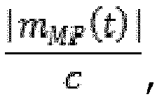
Fig. 8 ) may perform the ASSB scheme as depicted byFig. 3 of [reference 2], wherein for the term
- At an output of the ASSB scheme of
Fig. 3 of [reference 2], e.g. based on an input of the first digital signal d1 to the ASSB scheme as depicted byFig. 3 of [reference 2], a first intermediate signal
Fig. 9C . As can be seen, it comprises an upper sideband RSB around frequency fint, a lower sideband LSB, and a constant component DC atfrequency 0. Note that the spectrum of said first intermediate signal is1 as depicted byFig. 9C corresponds with an electrical baseband range, as an example below e.g. 50 GHz, as opposed to the optical signal spectrum around e.g. about 194 THz as depicted byFig. 9A, 9B . This is i.a. due to the envelope detection using thephotodiode 124a as explained above. - According to a further embodiment, a filtering process is applied to the (spectrum of said) first intermediate signal is1, cf.
Fig. 9C , which removes the lower sideband LSB and the constant component DC, and which leads to a filtered signal the spectrum of which is depicted byFig. 9D . As can be seen, the upper sideband RSB around intermediate frequency fint is obtained. - According to a further embodiment, the upper sideband RSB is frequency-shifted by said intermediate frequency fint to place it preferably symmetrically around the frequency f=0, whereby a shifted upper sideband RSB' in a low-pass frequency range is obtained, cf.
Fig. 9E , which corresponds e.g. to I/Q signals that may be further processed by a digital signal processor (DSP) 128, e.g. for applying conventional signal processing. - According to a further embodiment, the above-explained application of the ASSB scheme as depicted by
Fig. 3 of [reference 2] may also be performed by saidDSP 128, or by another calculating unit. -
Figure 10 schematically depicts a flow-chart of a method of operating the signal reconstruction stage 126 (Fig. 8 ) according to a preferred embodiment. Initially, the first digital signal d1 as obtained at an output ofblock 124 ofFig. 8 is input as an input signal u1 to block 400 ofFig. 10 , which processes said input signal u1 according to the equation u2=u1·cos{H[ln(u1)]}, wherein cos () is the cosine function, wherein H[] is the Hilbert transformation, wherein ln() is the natural logarithm, wherein an output signal u2 is obtained. - In other words, block 400 of
Fig. 10 implements an ASSB converter as depicted byFig. 3 of [reference 2], wherein the input signal u1 corresponds to term
term 
Fig. 3 of [reference 2]. An exemplary spectrum of the output signal u2 is depicted byFig. 9C and has already been explained above. - Subsequent block 402 (
Fig. 10 ) applies a filtering process to output signal u2, wherein the lower sideband LSB (Fig. 9C ) and the constant component DC is removed, which leads to signal u3, having a spectrum as depicted byFig. 9D . - Subsequent block 404 (
Fig. 10 ) applies frequency shifting to said signal u3 by said intermediate frequency fint (Fig. 9D ) to place it preferably symmetrically around the frequency of zero, f=0, whereby a signal spectrum of resulting signal u4 (Fig. 10 ) in a low-pass frequency range is obtained, cf.Fig. 9E . Signal u4 is a complex-valued signal having I and Q components. - Optionally, signal u4 may be downsampled (decimation) in
step 406, wherein a decimated signal u5 is obtained. - The above-explained process illustrated by
Fig. 10 effects a transformation of said first digital signal d1 into two output signals characterizing a phase and an amplitude or I and Q components (characterising complex signal values) of a first polarization of said modulated optical signal s5'. - According to a further embodiment, the above-explained process illustrated by
Fig. 10 may be performed by saidDSP 128. - According to a further embodiment, the above-explained process illustrated by
Fig. 10 may also be performed for said second digital signal d2. In this case, a transformation of said second digital signal d2 into two further output signals characterizing a phase and an amplitude or I, Q values of the second polarization of said modulated optical signal s5' is effected. -
Figure 6A schematically depicts a flowchart of a method of operating the optical transceiver 100 (Fig. 1 ) according to an embodiment. In afirst step 200, said continuous optical signal s01 is provided at said first frequency f1. In asubsequent step 210, said continuous optical signal s01 is power split to produce the optical carrier signal s1 and said local oscillator signal s6 for said Kramers-Kronigcoherent receiver 120. In an optional further step 220, saidtransceiver 100a modulates said optical carrier signal s1 to generate a modulated optical output signal s2, e.g. for transmission via an optical transmission channel to a remote optical receiver. Saidtransceiver 100a may also receive a modulated optical signal s5' and may add said local oscillator signal s6 with said received optical signal s5' to enable demodulation of a data stream from said received modulated optical signal s5'. -
Figure 6B schematically depicts a simplified flowchart of a method of operating the optical transceiver 100 (Fig. 1 ) according to a further embodiment. - In
step 250, aninput stage 122 of the Kramers-Kronig coherent receiver 120 (Fig. 1 ) receives a modulated optical signal s5', and instep 252 said local oscillator signal s6 is added to said received modulated optical signal s5' to enable further processing of the so obtained sum signal. After this digital signals d1, d2 as explained above with reference tofigure 1 are obtained from said sum signal (step not shown infigure 6B ), and insubsequent step 254, said digital signals d1, d2 are transformed by said signal reconstruction stage 126 (Fig. 1 ) into output signals characterising a phase and an amplitude of two polarisations of said modulated optical signal s5'. In the further,optional step 256, a demodulation based on said output signals of thesignal reconstruction stage 126 may be done. -
Figure 2 schematically depicts a block diagram of anoptical transmission system 1000 according to an embodiment. Theoptical transmission system 1000 comprises twooptical transceivers optical transceiver 100 ofFig. 1 . For example, theoptical transmitters 110 with theoptical modulators 112 and the Kramers-Kronigcoherent receivers 120 may be identical regarding their configuration and/or functionality for bothoptical transceivers - The first
optical transceiver 100a comprises afirst laser source 131 which is configured to provide a first, preferably continuous, optical signal s01 at a first frequency f1, cf.Fig. 3A . - The second
optical transceiver 100b comprises asecond laser source 132 which is configured to provide a second, preferably continuous, optical signal s02 at a second frequency f2, cf.Fig. 3A . The second frequency f2 is shifted with respect to said first frequency f1 by a non-vanishing second frequency shift Δf2. Preferably, absolute values of said first and second frequency shifts Δf1, Δf2 are equal. - An optical output of the
transmitter 110 of the firstoptical transceiver 100a is connected with an optical input of a Kramers-Kronigcoherent receiver 120 of said secondoptical transceiver 100b via a firstoptical fiber link 1002a, and an optical output of thetransmitter 110 of the secondoptical transceiver 100b is connected with an optical input of a Kramers-Kronigcoherent receiver 120 of said firstoptical transceiver 100a via a secondoptical fiber link 1002b. This way, thetransceivers -
Figure 7A schematically depicts a simplified flow-chart of a method of operating theoptical transmission system 1000 offigure 4 according to an embodiment. In afirst step 300, thelaser source 131 of said firstoptical transceiver 100a provides said first continuous optical signal s01.In afurther step 310, thelaser source 132 of said secondoptical transceiver 100b provides said second continuous optical signal s02, a center frequency of which being different from the center frequency of said first continuous optical signal s01, the frequency difference being expressed by said second frequency shift Δf2. In a further optional step, 320 thetransceivers - According to some embodiments, at least some of the
steps -
Figure 7B schematically depicts a simplified flow-chart of a method of operating theoptical transmission system 1000 offigure 4 according to a further embodiment. - In
step 322a, the firstoptical transceiver 100a (Fig. 2 ) derives a first optical carrier signal s1 and a first local oscillator signal s6 from said first optical signal s01. Instep 322b, the secondoptical transceiver 100b (Fig. 2 ) derives a second optical carrier signal s4 and a second local oscillator signal s3 from said second optical signal s02. In view of the second frequency shift Δf2 between the signals s01, s02, the same second frequency shift Δf2 is also present between the first and second optical carrier signals s1, s2 and the first and second local oscillator signals s6, s3. - In
step 324a, themodulator 112 of said firstoptical transceiver 100a modulates said first optical carrier signal s1 with a first symbol rate, to obtain a first modulated optical output signal s2. Instep 324b, themodulator 112 of said secondoptical transceiver 100b modulates said second optical carrier signal s4 with a second symbol rate, to obtain a second modulated optical output signal s5. According to an embodiment, said second symbol rate is equal to said first symbol rate. - In
step 326a, the firstoptical transceiver 100a transmits said first modulated optical output signal s2 via the firstoptical fiber link 1002a to the secondoptical transceiver 100b. Instep 326b, the secondoptical transceiver 100b transmits said second modulated optical output signal s5 via the secondoptical fiber link 1002b to the firstoptical transceiver 100a - In
step 328a, said first modulated optical output signal s2 is received as signal s2', which is an attenuated version of signal s2. As is well-known, other linear and/or nonlinear effects may also influence the transmitted signal s2 resulting in the received signal s2', which, however is not relevant for the further explanations of the embodiments. Similarly, instep 328b, said second modulated optical output signal s5 is received as signal s5'. - According to some embodiments, one or more amplifiers (not shown), e.g. optical fiber amplifiers (for example, of the EDFA type) and the like, may be provided within said
optical fiber link 1002a and/or saidoptical fiber link 1002b. - Optionally, in
steps Fig. 6B . - According to some embodiments, at least some of the
steps 322a to 328b above may also be performed simultaneously to each other or in another sequence as explained above. -
Fig. 3B depicts a signal spectrum SS2 associated with said modulated optical output signal s5 of the secondoptical transceiver 100b (Fig. 2 ). As the firstoptical transceiver 100a provides a local oscillator signal s6 with the first frequency f1 (Fig. 3B ), an efficient signal processing by means of the Kramers-Kronigcoherent receiver 120 is enabled. The same applies to the first signal transmission direction from the firstoptical transceiver 100a, cf. said modulated optical output signal s2, and its processing within the Kramers-Kronigcoherent receiver 120 of the secondoptical transceiver 100b. For the second frequency shift Δf2 and potential associated frequency ranges, similar observations apply as explained above for the first frequency shift Δf1 and its potential ranges r1, r2 with respect toFig. 3A, 3C . -
Figure 4 schematically depicts a block diagram of anoptical transmission system 1000a according to a further embodiment. Thesystem 1000a may be considered as a point-to-point wavelength division multiplexed (WDM) system, as a plurality of wavelength channels (or frequency channels, respectively) are transmitted in the same fiber. - According to the present embodiment, n many optical transceivers are provided at a first location, wherein the transmitters of said n many optical transceivers are denoted in
Fig. 4 withreference signs Fig. 4 withreference signs Fig. 4 may form oneoptical transceiver 100 as explained above with reference toFig. 1 and may comprise at least a similar configuration and/or functionality as saidtransceiver 100. In other words, the nmany transmitters many receivers Fig. 4 may be provided in the form of n many optical transceivers of thetype 100 as explained with reference toFig. 1 . - Also, n many further optical transceivers are provided at a second location, wherein the transmitters of said n many further optical transceivers are denoted in
Fig. 4 withreference signs 110n, 110o, ..., 110z, and wherein the receivers of said n many further optical transceivers are denoted inFig. 4 withreference signs 120n, 120o, ..., 120z. According to a preferred embodiment, each 2-tuple of transmitter and receiver (110i, 120i), i= n..z, ofFig. 4 may form one furtheroptical transceiver 100 as explained above with reference toFig. 1 and may comprise at least a similar configuration and/or functionality as saidtransceiver 100. In other words, the n manyfurther transmitters 110n, 110o, ..., 110z and n manyfurther receivers 120n, 120o, ..., 120z ofFig. 4 may be provided in the form of n many further optical transceivers of thetype 100 as explained with reference toFig. 1 . - As can be seen from
Fig. 4 , thetransmitters first transmitter multiplexer 1004a, and thereceivers 120n, 120o, ..., 120z are coupled to afirst receiver multiplexer 1006a, wherein saidmultiplexers optical fiber 1002c. This configuration e.g. enables thetransmitter 110a to transmit (modulated) optical output signals s2 (Fig. 2 ) to thereceiver 120n, thetransmitter 110b to transmit (modulated) optical output signals to the receiver 120o, and so on. - Similarly, the
transmitters 110n, 110o, ..., 110z are coupled to asecond transmitter multiplexer 1004b, and thereceivers second receiver multiplexer 1006b, wherein saidmultiplexers optical fiber 1002d. This configuration e.g. enables thetransmitter 110n to transmit (modulated) optical output signals s5 (Fig. 2 ) to thereceiver 120a, the transmitter 110o to transmit (modulated) optical output signals to thereceiver 120b, and so on. - A resulting first WDM transmission signal in a first transmission direction is denoted with reference sign s7 in
Fig. 4 . At an output of theoptical fiber 1002c, said first WDM transmission signal s7 is provided as signal s7' to thefirst receiver multiplexer 1006a. A resulting second WDM transmission signal in a second transmission direction is denoted with reference sign s8 inFig. 4 . At an output of theoptical fiber 1002d, said second WDM transmission signal s8 is provided as signal s8' to thesecond receiver multiplexer 1006b. - According to a preferred embodiment, each of said n many optical transceivers of
Fig. 4 comprises a laser source a signal frequency of which is shifted with respect to the signal frequency of the other optical transceivers by a predetermined channel spacing to enable a proper WDM transmission scheme. This is exemplarily depicted for six carrier frequencies f11 to f16 as illustrated byFig. 5 . - As an example, a first transceiver, which comprises the
transmitter 110a and thereceiver 120a ofFig. 4 , comprises a laser source (not shown) providing a continuous optical signal at frequency f11, a second transceiver, which comprises thetransmitter 110b and thereceiver 120b, comprises a laser source (not shown) providing a continuous optical signal at frequency f12, and so on, wherein the channel spacing CS (Fig. 5 ) characterizes a difference of neighbouring carrier frequencies f11, f12. Preferably, said channel spacing CS is substantially constant for all transceivers. - Similarly, each of said n many further optical transceivers comprising the
components 120n to 120z and 110n to 110z ofFig. 4 comprises a laser source a signal frequency of which is shifted with respect to the signal frequency of the other further optical transceivers by said predetermined channel spacing CS to enable said WDM transmission scheme. This is exemplarily depicted for six carrier frequencies f21 to f26 as illustrated byFig. 5 . - As an example, a first further transceiver, which comprises the
transmitter 110n and thereceiver 120n ofFig. 4 , comprises a laser source (not shown) providing a continuous optical signal at frequency f21, a second further transceiver, which comprises the transmitter 110o and the receiver 120o ofFig. 4 , comprises a laser source (not shown) providing a continuous optical signal at frequency f22, and so on, wherein the channel spacing CS characterizes a difference of neighbouring carrier frequencies f21, f22. Preferably, said channel spacing CS is substantially constant for all further transceivers, too. - Advantageously, the respective center frequencies f21, f22, ... of the further optical transceivers of the present embodiment (or of their laser sources, respectively) are frequency-shifted with respect to the center frequencies f11, f12, ... by a predetermined second frequency shift Δf2' (
Fig. 5 ). - This enables n many transceiver pairs according to
Fig. 4 to each operate in the way explained above in detail with reference to thetransceiver pair Fig. 2 ,3A, 3B . - As an example, a first transceiver pair of this type may comprise
transmitter 110a andreceiver 120a constituting a first transceiver of said transceiver pair, andtransmitter 110n andreceiver 120n as a second transceiver of said transceiver pair. As their local laser sources provide continuous optical signals with respectively shifted (center) frequencies of f11 and f21, an efficient signal reception, optical downconversion and further processing by means of their respective Kramers-Kronig coherent receivers is enabled. The same advantages are obtained for further transceiver pairs of the configuration ofFig. 4 , that operate within other WDM channels, i.e. different center frequencies, e.g. f12 and f22, while the relative frequency shift of their respective local laser sources is also characterized by said second frequency shift Δf2'. - According to a further embodiment, the channel spacing for the WDM scheme is at least slightly greater than a symbol rate R used for modulating said optical carrier signals.
- According to a further embodiment, the second frequency shift Δf2' may be greater than about 40 percent of a said symbol rate. According to further embodiments, other values and/or ranges may be employed for said second frequency shift Δf2', similar to those values and/or ranges explained above with respect to
Fig. 3A, 3B, 3C . - The description and drawings merely illustrate the principles of the invention. It will thus be appreciated that those skilled in the art will be able to devise various arrangements that, although not explicitly described or shown herein, embody the principles of the invention and are included within its spirit and scope. Furthermore, all examples recited herein are principally intended expressly to be only for pedagogical purposes to aid the reader in understanding the principles of the invention and the concepts contributed by the inventor(s) to furthering the art, and are to be construed as being without limitation to such specifically recited examples and conditions. Moreover, all statements herein reciting principles, aspects, and embodiments of the invention, as well as specific examples thereof, are intended to encompass equivalents thereof.
- It should be appreciated by those skilled in the art that any block diagrams herein represent conceptual views of illustrative circuitry embodying the principles of the invention. Similarly, it will be appreciated that any flow charts, flow diagrams, state transition diagrams, pseudo code, and the like represent various processes which may be substantially represented in computer readable medium and so executed by a computer or processor, whether or not such computer or processor is explicitly shown.
- A person of skill in the art would readily recognize that steps of various above-described methods can be performed by programmed computers. Herein, some embodiments are also intended to cover program storage devices, e.g., digital data storage media, which are machine or computer readable and encode machine-executable or computer-executable programs of instructions, wherein said instructions perform some or all of the steps of said above-described methods. The program storage devices may be, e.g., digital memories, magnetic storage media such as a magnetic disks and magnetic tapes, hard drives, or optically readable digital data storage media. The embodiments are also intended to cover computers programmed to perform said steps of the above-described methods.
- The functions of the various elements shown in the FIGs., including any functional blocks labeled as "processors", may be provided through the use of dedicated hardware as well as hardware capable of executing software in association with appropriate software. When provided by a processor, the functions may be provided by a single dedicated processor, by a single shared processor, or by a plurality of individual processors, some of which may be shared. Moreover, explicit use of the term "processor" or "controller" should not be construed to refer exclusively to hardware capable of executing software, and may implicitly include, without limitation, digital signal processor (DSP) hardware, network processor, application specific integrated circuit (ASIC), field programmable gate array (FPGA), read only memory (ROM) for storing software, random access memory (RAM), and non-volatile storage. Other hardware, conventional and/or custom, may also be included. Similarly, any switches shown in the FIGS. are conceptual only. Their function may be carried out through the operation of program logic, through dedicated logic, through the interaction of program control and dedicated logic, or even manually, the particular technique being selectable by the implementer as more specifically understood from the context.
- It should be appreciated by those skilled in the art that any block diagrams herein represent conceptual views of illustrative circuitry embodying the principles of the invention. Similarly, it will be appreciated that any flow charts, flow diagrams, state transition diagrams, pseudo code, and the like represent various processes which may be substantially represented in computer readable medium and so executed by a computer or processor, whether or not such computer or processor is explicitly shown.
Claims (17)
- Optical transceiver (100; 100a, 100b) comprising an optical transmitter (110) having an optical modulator (112) for modulating (222) an optical carrier signal (s1), a coherent optical receiver (120) for demodulating data from a received data-modulated optical signal (s5, s5'), and a laser source (130; 131, 132) being connected to provide (200), at a first frequency (f1), the optical carrier signal (s1) and an optical local oscillator signal (s6), the coherent optical receiver (120) being configured to demodulate data from said received data-modulated optical signal (s5, s5') at a second carrier frequency (f2), the second carrier frequency (f2) being shifted from said first frequency (f1) by a first frequency shift (Δf1).
- Optical transceiver (100; 100a, 100b) according to claim 1, wherein said first frequency shift (Δf1) ranges between about 40 percent of a symbol rate of said modulated optical signals (s5') and about 65 percent of said symbol rate of said modulated optical signals (s5').
- Optical transceiver (100; 100a, 100b) according to one of the preceding claims, wherein said coherent optical receiver (120) comprises an input stage (122) which is configured to receive (250) said modulated optical signal (s5, s5') and said local oscillator signal (s6), and to add (252) said local oscillator signal (s6) to said modulated optical signal (s5, s5') .
- Optical transceiver (100; 100a, 100b) according to claim 3, wherein said coherent optical receiver (120) is configured to convert two output signals of said input stage (122) from the optical domain to the electrical domain, wherein two electrical output signals are obtained, and to perform an analog-to-digital conversion of said two electrical output signals to obtain two digital signals (d1, d2).
- Optical transceiver (100; 100a, 100b) according to claim 4, wherein said coherent optical receiver (120) comprises a signal reconstruction stage (126) configured to transform (254) said two digital signals (d1, d2) into output signals characterizing a phase and an amplitude of two polarizations of said modulated optical signal (s5, s5').
- Optical transceiver (100; 100a, 100b) according to one of the preceding claims, wherein said optical modulator (112) is a polarisation division multiplexing, PDM, I/Q modulator configured to provide two orthogonal polarizations of said optical carrier signal (s1) and to modulate (222) phase and amplitude of said two orthogonal polarizations.
- Optical transceiver (100; 100a, 100b) according to one of the preceding claims, wherein said first frequency (f1) is shifted from said second frequency (f2) by, at least, about half of a baud rate of said optical receiver (120).
- Optical transceiver (100; 100a, 100b) according to one of the preceding claims, wherein said first frequency (f1) is shifted from said second frequency (f2) by, at least, about half of a baud rate of said optical modulator (112).
- Optical transceiver (100; 100a, 100b) according to one of the preceding claims, further comprising an optical power splitter (140) connected to receive light from said laser source (130) and to produce said optical carrier signal (s1) on one optical output thereof and to produce said optical local oscillator signal (s6) on another output thereof.
- Method of operating an optical transceiver (100; 100a, 100b) comprising an optical transmitter (110) having an optical modulator (112) for modulating an optical carrier signal (s1), a coherent optical receiver (120) for demodulating data from a received data-modulated optical signal (s5, s5'), and a laser source (130; 131, 132), wherein said method comprises: providing (200), by means of a laser source (130), at a first frequency (f1), the optical carrier signal (s1) and an optical local oscillator signal (s6), said coherent optical receiver (120) demodulating data from said received data-modulated optical signal (s5, s5') at a second carrier frequency (f2), the second carrier frequency (f2) being shifted from said first frequency (f1) by a first frequency shift (Δf1).
- Optical transmission system (1000; 1000a) comprising at least two optical transceivers (100a, 100b) according to one of the claims 1 to 9, wherein a laser source (131) of a first one (100a) of said at least two transceivers (100a, 100b) is configured to provide a first optical signal (s01) at said first frequency (f1; f11), wherein a laser source (132) of a second one (100b) of said at least two transceivers (100a, 100b) is configured to provide a second optical signal (s02) at a second frequency (f2; f21), which is shifted with respect to said first frequency (f1) by a non-vanishing second frequency shift (Δf2; Δf2').
- Optical transmission system (1000; 1000a) according to claim 11, wherein said first optical transceiver (100a) is configured to provide a first modulated optical output signal (s2) with a first symbol rate, and wherein said second frequency shift (Δf2) ranges between about 40 percent of a symbol rate of said first modulated optical output signal (s2) and about 65 percent of said symbol rate of said first modulated optical output signal (s2).
- Method of operating an optical transmission system (1000; 1000a) comprising at least two optical transceivers (100a, 100b) according to one of the claims 1 to 9, said method comprising: providing (300), by means of a laser source (131) of a first one (100a) of said at least two transceivers (100a, 100b), a first optical signal (s01) at said first frequency (f1; f11), providing (310), by means of a laser source (132) of a second one (100b) of said at least two transceivers (100a, 100b), a second optical signal (s02) at a second frequency (f2; f21), which is shifted with respect to said first frequency (f1) by a non-vanishing second frequency shift (Δf2; Δf2').
- Method according to claim 13, said method further comprising: providing (322a), by means of a laser source (131) of said first optical transceiver (100a), a first optical carrier signal (s1) and a first local oscillator signal (s6), providing (322b), by means of a laser source (132) of said second optical transceiver (100b), a second optical carrier signal (s4) and a second local oscillator signal (s3).
- Method according to one of the claims 13 to 14, said method further comprising: modulating (324a), by means of an optical modulator (112) of said first optical transceiver (100a), said first optical carrier signal (s1) with a first symbol rate, to obtain a first modulated optical output signal (s2), and modulating (324b), by means of an optical modulator (112) of said second optical transceiver (100b), said second optical carrier signal (s4) with a second symbol rate, to obtain a second modulated optical output signal (s5).
- Method according to claim 15, said method further comprising: transmitting (326a) said first modulated optical output signal (s2) to an optical receiver (120) of said second transceiver (100b), and transmitting (326b) said second modulated optical output signal (s5) to an optical receiver (120) of said first transceiver (100a).
- Method according to claim 14, said method further comprising: receiving and processing (328a) said first modulated optical output signal (s2) at the receiver (120) of said second transceiver (100b), and receiving and processing (328b) said second modulated optical output signal (s5) at the receiver (120) of said first transceiver (100a).
Priority Applications (1)
| Application Number | Priority Date | Filing Date | Title |
|---|---|---|---|
| EP17164195.4A EP3382910B1 (en) | 2017-03-31 | 2017-03-31 | Optical transceiver and method of operating an optical transceiver |
Applications Claiming Priority (1)
| Application Number | Priority Date | Filing Date | Title |
|---|---|---|---|
| EP17164195.4A EP3382910B1 (en) | 2017-03-31 | 2017-03-31 | Optical transceiver and method of operating an optical transceiver |
Publications (2)
| Publication Number | Publication Date |
|---|---|
| EP3382910A1 true EP3382910A1 (en) | 2018-10-03 |
| EP3382910B1 EP3382910B1 (en) | 2020-09-09 |
Family
ID=58548515
Family Applications (1)
| Application Number | Title | Priority Date | Filing Date |
|---|---|---|---|
| EP17164195.4A Active EP3382910B1 (en) | 2017-03-31 | 2017-03-31 | Optical transceiver and method of operating an optical transceiver |
Country Status (1)
| Country | Link |
|---|---|
| EP (1) | EP3382910B1 (en) |
Cited By (3)
| Publication number | Priority date | Publication date | Assignee | Title |
|---|---|---|---|---|
| CN115296749A (en) * | 2022-09-29 | 2022-11-04 | 网络通信与安全紫金山实验室 | Envelope detection photon millimeter wave terahertz communication system and method |
| CN117675033A (en) * | 2024-02-02 | 2024-03-08 | 网络通信与安全紫金山实验室 | A photonic terahertz distributed antenna system and terahertz signal transmission method |
| WO2024123683A3 (en) * | 2022-12-05 | 2024-10-10 | Lucidean, Inc. | Homodyne bidirectional optical transceiver |
Citations (1)
| Publication number | Priority date | Publication date | Assignee | Title |
|---|---|---|---|---|
| US7209664B1 (en) * | 2003-06-10 | 2007-04-24 | Nortel Networks Limited | Frequency agile transmitter and receiver architecture for DWDM systems |
-
2017
- 2017-03-31 EP EP17164195.4A patent/EP3382910B1/en active Active
Patent Citations (1)
| Publication number | Priority date | Publication date | Assignee | Title |
|---|---|---|---|---|
| US7209664B1 (en) * | 2003-06-10 | 2007-04-24 | Nortel Networks Limited | Frequency agile transmitter and receiver architecture for DWDM systems |
Non-Patent Citations (3)
| Title |
|---|
| "Envelope Detection of ''Full Carrier'' SSB'' to ''Implementation of ASSB", pages: 24 - 27 |
| ANTONIO MECOZZI; CRISTIAN ANTONELLI; MARK SHTAIF: "Kramers-Kronig coherent receiver", OPTICA, vol. 3.11, 2016, pages 1220 - 1227, XP002773963 |
| VOELCKER, H.: "Demodulation of Single-Sideband Signals via Envelope Detection", IEEE TRANSACTIONS ON COMMUNICATION TECHNOLOGY, vol. COM-14, February 1966 (1966-02-01), pages 22 - 30, XP011217789 |
Cited By (4)
| Publication number | Priority date | Publication date | Assignee | Title |
|---|---|---|---|---|
| CN115296749A (en) * | 2022-09-29 | 2022-11-04 | 网络通信与安全紫金山实验室 | Envelope detection photon millimeter wave terahertz communication system and method |
| CN115296749B (en) * | 2022-09-29 | 2023-02-03 | 网络通信与安全紫金山实验室 | Envelope detection photon millimeter wave terahertz communication system and method |
| WO2024123683A3 (en) * | 2022-12-05 | 2024-10-10 | Lucidean, Inc. | Homodyne bidirectional optical transceiver |
| CN117675033A (en) * | 2024-02-02 | 2024-03-08 | 网络通信与安全紫金山实验室 | A photonic terahertz distributed antenna system and terahertz signal transmission method |
Also Published As
| Publication number | Publication date |
|---|---|
| EP3382910B1 (en) | 2020-09-09 |
Similar Documents
| Publication | Publication Date | Title |
|---|---|---|
| US8582979B2 (en) | Method and arrangement for transmitting an optical OFDM-signal | |
| US8437638B2 (en) | Optical modulation circuit and optical transmission system | |
| US11652553B2 (en) | Optical signal transmission system and optical signal transmission method | |
| EP3039800B1 (en) | Optical transmitters with unbalanced optical sidebands separated by gaps | |
| US10003409B2 (en) | Imaging cancellation in high-speed intensity modulation and direct detection system with dual single sideband modulation | |
| US8831439B2 (en) | Upsampling optical transmitter | |
| JP5059155B2 (en) | Optical communication improvements or improvements related to optical communications | |
| US5543952A (en) | Optical transmission system | |
| US9374260B2 (en) | Method and apparatus for directly detected optical transmission systems based on carrierless amplitude-phase modulation | |
| Bo et al. | Optical single-sideband transmitters | |
| US20050286908A1 (en) | Optical communication using duobinary modulation | |
| US9584223B2 (en) | Digital generation of multi-carrier optical signals | |
| EP2197165A1 (en) | Quadrature amplitude modulation signal generating device | |
| US8768174B2 (en) | Modulation device and modulation method, and demodulation device and demodulation method | |
| US10014954B2 (en) | Imaging cancellation in high-speed intensity modulation and direct detection system with dual single sideband modulation | |
| EP3382910B1 (en) | Optical transceiver and method of operating an optical transceiver | |
| Misra et al. | Optical channel aggregation based on modulation format conversion by coherent spectral superposition with electro-optic modulators | |
| EP3648377B1 (en) | Optical transmitter, optical receiver and communication system | |
| US20150244467A1 (en) | Optical transmission device and optical reception device | |
| CN106877934A (en) | Carrier Suppression Mode Optical Carrier Vector Wave System Based on Phase Factor Optimization | |
| CN117527074A (en) | Full duplex RoF forward method with same-frequency self-interference optical domain elimination function | |
| CN113965443A (en) | Transmitting device, receiving device, terahertz wireless communication system and method | |
| JP6363933B2 (en) | Optical transmitter / receiver, optical receiver, and optical transmitter / receiver method | |
| JP5202650B2 (en) | Optical modulation / demodulation system, optical transmission system, and optical modulation / demodulation method | |
| Misra et al. | Reconfigurable and Real-Time Nyquist OTDM Demultiplexing in Silicon Photonics |
Legal Events
| Date | Code | Title | Description |
|---|---|---|---|
| PUAI | Public reference made under article 153(3) epc to a published international application that has entered the european phase |
Free format text: ORIGINAL CODE: 0009012 |
|
| STAA | Information on the status of an ep patent application or granted ep patent |
Free format text: STATUS: THE APPLICATION HAS BEEN PUBLISHED |
|
| AK | Designated contracting states |
Kind code of ref document: A1 Designated state(s): AL AT BE BG CH CY CZ DE DK EE ES FI FR GB GR HR HU IE IS IT LI LT LU LV MC MK MT NL NO PL PT RO RS SE SI SK SM TR |
|
| AX | Request for extension of the european patent |
Extension state: BA ME |
|
| STAA | Information on the status of an ep patent application or granted ep patent |
Free format text: STATUS: REQUEST FOR EXAMINATION WAS MADE |
|
| 17P | Request for examination filed |
Effective date: 20190403 |
|
| RBV | Designated contracting states (corrected) |
Designated state(s): AL AT BE BG CH CY CZ DE DK EE ES FI FR GB GR HR HU IE IS IT LI LT LU LV MC MK MT NL NO PL PT RO RS SE SI SK SM TR |
|
| STAA | Information on the status of an ep patent application or granted ep patent |
Free format text: STATUS: EXAMINATION IS IN PROGRESS |
|
| RAP1 | Party data changed (applicant data changed or rights of an application transferred) |
Owner name: NOKIA SOLUTIONS AND NETWORKS OY |
|
| 17Q | First examination report despatched |
Effective date: 20190813 |
|
| GRAP | Despatch of communication of intention to grant a patent |
Free format text: ORIGINAL CODE: EPIDOSNIGR1 |
|
| STAA | Information on the status of an ep patent application or granted ep patent |
Free format text: STATUS: GRANT OF PATENT IS INTENDED |
|
| INTG | Intention to grant announced |
Effective date: 20200409 |
|
| GRAS | Grant fee paid |
Free format text: ORIGINAL CODE: EPIDOSNIGR3 |
|
| GRAA | (expected) grant |
Free format text: ORIGINAL CODE: 0009210 |
|
| STAA | Information on the status of an ep patent application or granted ep patent |
Free format text: STATUS: THE PATENT HAS BEEN GRANTED |
|
| AK | Designated contracting states |
Kind code of ref document: B1 Designated state(s): AL AT BE BG CH CY CZ DE DK EE ES FI FR GB GR HR HU IE IS IT LI LT LU LV MC MK MT NL NO PL PT RO RS SE SI SK SM TR |
|
| REG | Reference to a national code |
Ref country code: GB Ref legal event code: FG4D |
|
| REG | Reference to a national code |
Ref country code: AT Ref legal event code: REF Ref document number: 1312866 Country of ref document: AT Kind code of ref document: T Effective date: 20200915 Ref country code: CH Ref legal event code: EP |
|
| REG | Reference to a national code |
Ref country code: DE Ref legal event code: R096 Ref document number: 602017023106 Country of ref document: DE |
|
| REG | Reference to a national code |
Ref country code: IE Ref legal event code: FG4D |
|
| REG | Reference to a national code |
Ref country code: LT Ref legal event code: MG4D |
|
| PG25 | Lapsed in a contracting state [announced via postgrant information from national office to epo] |
Ref country code: NO Free format text: LAPSE BECAUSE OF FAILURE TO SUBMIT A TRANSLATION OF THE DESCRIPTION OR TO PAY THE FEE WITHIN THE PRESCRIBED TIME-LIMIT Effective date: 20201209 Ref country code: BG Free format text: LAPSE BECAUSE OF FAILURE TO SUBMIT A TRANSLATION OF THE DESCRIPTION OR TO PAY THE FEE WITHIN THE PRESCRIBED TIME-LIMIT Effective date: 20201209 Ref country code: SE Free format text: LAPSE BECAUSE OF FAILURE TO SUBMIT A TRANSLATION OF THE DESCRIPTION OR TO PAY THE FEE WITHIN THE PRESCRIBED TIME-LIMIT Effective date: 20200909 Ref country code: LT Free format text: LAPSE BECAUSE OF FAILURE TO SUBMIT A TRANSLATION OF THE DESCRIPTION OR TO PAY THE FEE WITHIN THE PRESCRIBED TIME-LIMIT Effective date: 20200909 Ref country code: HR Free format text: LAPSE BECAUSE OF FAILURE TO SUBMIT A TRANSLATION OF THE DESCRIPTION OR TO PAY THE FEE WITHIN THE PRESCRIBED TIME-LIMIT Effective date: 20200909 Ref country code: GR Free format text: LAPSE BECAUSE OF FAILURE TO SUBMIT A TRANSLATION OF THE DESCRIPTION OR TO PAY THE FEE WITHIN THE PRESCRIBED TIME-LIMIT Effective date: 20201210 Ref country code: FI Free format text: LAPSE BECAUSE OF FAILURE TO SUBMIT A TRANSLATION OF THE DESCRIPTION OR TO PAY THE FEE WITHIN THE PRESCRIBED TIME-LIMIT Effective date: 20200909 |
|
| REG | Reference to a national code |
Ref country code: AT Ref legal event code: MK05 Ref document number: 1312866 Country of ref document: AT Kind code of ref document: T Effective date: 20200909 |
|
| REG | Reference to a national code |
Ref country code: NL Ref legal event code: MP Effective date: 20200909 |
|
| PG25 | Lapsed in a contracting state [announced via postgrant information from national office to epo] |
Ref country code: LV Free format text: LAPSE BECAUSE OF FAILURE TO SUBMIT A TRANSLATION OF THE DESCRIPTION OR TO PAY THE FEE WITHIN THE PRESCRIBED TIME-LIMIT Effective date: 20200909 Ref country code: RS Free format text: LAPSE BECAUSE OF FAILURE TO SUBMIT A TRANSLATION OF THE DESCRIPTION OR TO PAY THE FEE WITHIN THE PRESCRIBED TIME-LIMIT Effective date: 20200909 Ref country code: PL Free format text: LAPSE BECAUSE OF FAILURE TO SUBMIT A TRANSLATION OF THE DESCRIPTION OR TO PAY THE FEE WITHIN THE PRESCRIBED TIME-LIMIT Effective date: 20200909 |
|
| PG25 | Lapsed in a contracting state [announced via postgrant information from national office to epo] |
Ref country code: SM Free format text: LAPSE BECAUSE OF FAILURE TO SUBMIT A TRANSLATION OF THE DESCRIPTION OR TO PAY THE FEE WITHIN THE PRESCRIBED TIME-LIMIT Effective date: 20200909 Ref country code: EE Free format text: LAPSE BECAUSE OF FAILURE TO SUBMIT A TRANSLATION OF THE DESCRIPTION OR TO PAY THE FEE WITHIN THE PRESCRIBED TIME-LIMIT Effective date: 20200909 Ref country code: CZ Free format text: LAPSE BECAUSE OF FAILURE TO SUBMIT A TRANSLATION OF THE DESCRIPTION OR TO PAY THE FEE WITHIN THE PRESCRIBED TIME-LIMIT Effective date: 20200909 Ref country code: PT Free format text: LAPSE BECAUSE OF FAILURE TO SUBMIT A TRANSLATION OF THE DESCRIPTION OR TO PAY THE FEE WITHIN THE PRESCRIBED TIME-LIMIT Effective date: 20210111 Ref country code: RO Free format text: LAPSE BECAUSE OF FAILURE TO SUBMIT A TRANSLATION OF THE DESCRIPTION OR TO PAY THE FEE WITHIN THE PRESCRIBED TIME-LIMIT Effective date: 20200909 |
|
| PG25 | Lapsed in a contracting state [announced via postgrant information from national office to epo] |
Ref country code: IS Free format text: LAPSE BECAUSE OF FAILURE TO SUBMIT A TRANSLATION OF THE DESCRIPTION OR TO PAY THE FEE WITHIN THE PRESCRIBED TIME-LIMIT Effective date: 20210109 Ref country code: ES Free format text: LAPSE BECAUSE OF FAILURE TO SUBMIT A TRANSLATION OF THE DESCRIPTION OR TO PAY THE FEE WITHIN THE PRESCRIBED TIME-LIMIT Effective date: 20200909 Ref country code: AL Free format text: LAPSE BECAUSE OF FAILURE TO SUBMIT A TRANSLATION OF THE DESCRIPTION OR TO PAY THE FEE WITHIN THE PRESCRIBED TIME-LIMIT Effective date: 20200909 Ref country code: AT Free format text: LAPSE BECAUSE OF FAILURE TO SUBMIT A TRANSLATION OF THE DESCRIPTION OR TO PAY THE FEE WITHIN THE PRESCRIBED TIME-LIMIT Effective date: 20200909 |
|
| REG | Reference to a national code |
Ref country code: DE Ref legal event code: R097 Ref document number: 602017023106 Country of ref document: DE |
|
| PG25 | Lapsed in a contracting state [announced via postgrant information from national office to epo] |
Ref country code: SK Free format text: LAPSE BECAUSE OF FAILURE TO SUBMIT A TRANSLATION OF THE DESCRIPTION OR TO PAY THE FEE WITHIN THE PRESCRIBED TIME-LIMIT Effective date: 20200909 |
|
| PLBE | No opposition filed within time limit |
Free format text: ORIGINAL CODE: 0009261 |
|
| STAA | Information on the status of an ep patent application or granted ep patent |
Free format text: STATUS: NO OPPOSITION FILED WITHIN TIME LIMIT |
|
| 26N | No opposition filed |
Effective date: 20210610 |
|
| PG25 | Lapsed in a contracting state [announced via postgrant information from national office to epo] |
Ref country code: SI Free format text: LAPSE BECAUSE OF FAILURE TO SUBMIT A TRANSLATION OF THE DESCRIPTION OR TO PAY THE FEE WITHIN THE PRESCRIBED TIME-LIMIT Effective date: 20200909 Ref country code: DK Free format text: LAPSE BECAUSE OF FAILURE TO SUBMIT A TRANSLATION OF THE DESCRIPTION OR TO PAY THE FEE WITHIN THE PRESCRIBED TIME-LIMIT Effective date: 20200909 |
|
| PG25 | Lapsed in a contracting state [announced via postgrant information from national office to epo] |
Ref country code: MC Free format text: LAPSE BECAUSE OF FAILURE TO SUBMIT A TRANSLATION OF THE DESCRIPTION OR TO PAY THE FEE WITHIN THE PRESCRIBED TIME-LIMIT Effective date: 20200909 Ref country code: IT Free format text: LAPSE BECAUSE OF FAILURE TO SUBMIT A TRANSLATION OF THE DESCRIPTION OR TO PAY THE FEE WITHIN THE PRESCRIBED TIME-LIMIT Effective date: 20200909 |
|
| REG | Reference to a national code |
Ref country code: CH Ref legal event code: PL |
|
| REG | Reference to a national code |
Ref country code: BE Ref legal event code: MM Effective date: 20210331 |
|
| PG25 | Lapsed in a contracting state [announced via postgrant information from national office to epo] |
Ref country code: CH Free format text: LAPSE BECAUSE OF NON-PAYMENT OF DUE FEES Effective date: 20210331 Ref country code: LI Free format text: LAPSE BECAUSE OF NON-PAYMENT OF DUE FEES Effective date: 20210331 Ref country code: LU Free format text: LAPSE BECAUSE OF NON-PAYMENT OF DUE FEES Effective date: 20210331 Ref country code: FR Free format text: LAPSE BECAUSE OF NON-PAYMENT OF DUE FEES Effective date: 20210331 Ref country code: IE Free format text: LAPSE BECAUSE OF NON-PAYMENT OF DUE FEES Effective date: 20210331 |
|
| PG25 | Lapsed in a contracting state [announced via postgrant information from national office to epo] |
Ref country code: BE Free format text: LAPSE BECAUSE OF NON-PAYMENT OF DUE FEES Effective date: 20210331 |
|
| PG25 | Lapsed in a contracting state [announced via postgrant information from national office to epo] |
Ref country code: NL Free format text: LAPSE BECAUSE OF NON-PAYMENT OF DUE FEES Effective date: 20200923 Ref country code: CY Free format text: LAPSE BECAUSE OF FAILURE TO SUBMIT A TRANSLATION OF THE DESCRIPTION OR TO PAY THE FEE WITHIN THE PRESCRIBED TIME-LIMIT Effective date: 20200909 |
|
| PG25 | Lapsed in a contracting state [announced via postgrant information from national office to epo] |
Ref country code: HU Free format text: LAPSE BECAUSE OF FAILURE TO SUBMIT A TRANSLATION OF THE DESCRIPTION OR TO PAY THE FEE WITHIN THE PRESCRIBED TIME-LIMIT; INVALID AB INITIO Effective date: 20170331 |
|
| PG25 | Lapsed in a contracting state [announced via postgrant information from national office to epo] |
Ref country code: MK Free format text: LAPSE BECAUSE OF FAILURE TO SUBMIT A TRANSLATION OF THE DESCRIPTION OR TO PAY THE FEE WITHIN THE PRESCRIBED TIME-LIMIT Effective date: 20200909 |
|
| PG25 | Lapsed in a contracting state [announced via postgrant information from national office to epo] |
Ref country code: MT Free format text: LAPSE BECAUSE OF FAILURE TO SUBMIT A TRANSLATION OF THE DESCRIPTION OR TO PAY THE FEE WITHIN THE PRESCRIBED TIME-LIMIT Effective date: 20200909 |
|
| PG25 | Lapsed in a contracting state [announced via postgrant information from national office to epo] |
Ref country code: TR Free format text: LAPSE BECAUSE OF FAILURE TO SUBMIT A TRANSLATION OF THE DESCRIPTION OR TO PAY THE FEE WITHIN THE PRESCRIBED TIME-LIMIT Effective date: 20200909 |
|
| PGFP | Annual fee paid to national office [announced via postgrant information from national office to epo] |
Ref country code: GB Payment date: 20260209 Year of fee payment: 10 |
|
| PGFP | Annual fee paid to national office [announced via postgrant information from national office to epo] |
Ref country code: DE Payment date: 20260204 Year of fee payment: 10 |