EP3382878A1 - Apparatus and method for controlling current - Google Patents
Apparatus and method for controlling current Download PDFInfo
- Publication number
- EP3382878A1 EP3382878A1 EP17203049.6A EP17203049A EP3382878A1 EP 3382878 A1 EP3382878 A1 EP 3382878A1 EP 17203049 A EP17203049 A EP 17203049A EP 3382878 A1 EP3382878 A1 EP 3382878A1
- Authority
- EP
- European Patent Office
- Prior art keywords
- output
- current
- transfer function
- plant
- applying
- Prior art date
- Legal status (The legal status is an assumption and is not a legal conclusion. Google has not performed a legal analysis and makes no representation as to the accuracy of the status listed.)
- Withdrawn
Links
Images



Classifications
-
- H—ELECTRICITY
- H02—GENERATION; CONVERSION OR DISTRIBUTION OF ELECTRIC POWER
- H02M—APPARATUS FOR CONVERSION BETWEEN AC AND AC, BETWEEN AC AND DC, OR BETWEEN DC AND DC, AND FOR USE WITH MAINS OR SIMILAR POWER SUPPLY SYSTEMS; CONVERSION OF DC OR AC INPUT POWER INTO SURGE OUTPUT POWER; CONTROL OR REGULATION THEREOF
- H02M1/00—Details of apparatus for conversion
- H02M1/12—Arrangements for reducing harmonics from AC input or output
- H02M1/126—Arrangements for reducing harmonics from AC input or output using passive filters
-
- H—ELECTRICITY
- H02—GENERATION; CONVERSION OR DISTRIBUTION OF ELECTRIC POWER
- H02M—APPARATUS FOR CONVERSION BETWEEN AC AND AC, BETWEEN AC AND DC, OR BETWEEN DC AND DC, AND FOR USE WITH MAINS OR SIMILAR POWER SUPPLY SYSTEMS; CONVERSION OF DC OR AC INPUT POWER INTO SURGE OUTPUT POWER; CONTROL OR REGULATION THEREOF
- H02M7/00—Conversion of AC power input into DC power output; Conversion of DC power input into AC power output
- H02M7/42—Conversion of DC power input into AC power output without possibility of reversal
- H02M7/44—Conversion of DC power input into AC power output without possibility of reversal by static converters
- H02M7/48—Conversion of DC power input into AC power output without possibility of reversal by static converters using discharge tubes with control electrode or semiconductor devices with control electrode
-
- H—ELECTRICITY
- H01—ELECTRIC ELEMENTS
- H01H—ELECTRIC SWITCHES; RELAYS; SELECTORS; EMERGENCY PROTECTIVE DEVICES
- H01H71/00—Details of the protective switches or relays covered by groups H01H73/00 - H01H83/00
- H01H71/10—Operating or release mechanisms
- H01H71/12—Automatic release mechanisms with or without manual release
- H01H71/24—Electromagnetic mechanisms
- H01H71/2472—Electromagnetic mechanisms with rotatable armatures
-
- G—PHYSICS
- G05—CONTROLLING; REGULATING
- G05F—SYSTEMS FOR REGULATING ELECTRIC OR MAGNETIC VARIABLES
- G05F1/00—Automatic systems in which deviations of an electric quantity from one or more predetermined values are detected at the output of the system and fed back to a device within the system to restore the detected quantity to its predetermined value or values, i.e. retroactive systems
- G05F1/10—Regulating voltage or current
- G05F1/12—Regulating voltage or current wherein the variable actually regulated by the final control device is AC
-
- G—PHYSICS
- G05—CONTROLLING; REGULATING
- G05F—SYSTEMS FOR REGULATING ELECTRIC OR MAGNETIC VARIABLES
- G05F1/00—Automatic systems in which deviations of an electric quantity from one or more predetermined values are detected at the output of the system and fed back to a device within the system to restore the detected quantity to its predetermined value or values, i.e. retroactive systems
- G05F1/10—Regulating voltage or current
- G05F1/46—Regulating voltage or current wherein the variable actually regulated by the final control device is DC
- G05F1/56—Regulating voltage or current wherein the variable actually regulated by the final control device is DC using semiconductor devices in series with the load as final control devices
- G05F1/565—Regulating voltage or current wherein the variable actually regulated by the final control device is DC using semiconductor devices in series with the load as final control devices sensing a condition of the system or its load in addition to means responsive to deviations in the output of the system, e.g. current, voltage, power factor
-
- H—ELECTRICITY
- H02—GENERATION; CONVERSION OR DISTRIBUTION OF ELECTRIC POWER
- H02J—ELECTRIC POWER NETWORKS; CIRCUIT ARRANGEMENTS OR SYSTEMS FOR SUPPLYING OR DISTRIBUTING ELECTRIC POWER; SYSTEMS FOR STORING ELECTRIC ENERGY
- H02J3/00—Circuit arrangements for AC mains or AC distribution networks
- H02J3/01—Arrangements for reducing harmonics or ripples
-
- H—ELECTRICITY
- H02—GENERATION; CONVERSION OR DISTRIBUTION OF ELECTRIC POWER
- H02M—APPARATUS FOR CONVERSION BETWEEN AC AND AC, BETWEEN AC AND DC, OR BETWEEN DC AND DC, AND FOR USE WITH MAINS OR SIMILAR POWER SUPPLY SYSTEMS; CONVERSION OF DC OR AC INPUT POWER INTO SURGE OUTPUT POWER; CONTROL OR REGULATION THEREOF
- H02M1/00—Details of apparatus for conversion
- H02M1/12—Arrangements for reducing harmonics from AC input or output
-
- Y—GENERAL TAGGING OF NEW TECHNOLOGICAL DEVELOPMENTS; GENERAL TAGGING OF CROSS-SECTIONAL TECHNOLOGIES SPANNING OVER SEVERAL SECTIONS OF THE IPC; TECHNICAL SUBJECTS COVERED BY FORMER USPC CROSS-REFERENCE ART COLLECTIONS [XRACs] AND DIGESTS
- Y02—TECHNOLOGIES OR APPLICATIONS FOR MITIGATION OR ADAPTATION AGAINST CLIMATE CHANGE
- Y02E—REDUCTION OF GREENHOUSE GAS [GHG] EMISSIONS, RELATED TO ENERGY GENERATION, TRANSMISSION OR DISTRIBUTION
- Y02E40/00—Technologies for an efficient electrical power generation, transmission or distribution
- Y02E40/40—Arrangements for reducing harmonics
Definitions
- Various embodiments relate to an apparatus and method for controlling current, and more particularly a proportional resonance (PR) control apparatus and an operating method thereof.
- PR proportional resonance
- a proportional and resonant (PR) control apparatus for controlling current is implemented on a stationary coordinate system of a single-phase or three-phase system to control alternating current, and is widely used in industry.
- the PR control apparatus theoretically has an infinite gain for a specific frequency, it has similar characteristics to those of a primary low-pass filter, in which a transfer function of a closed loop control system is a cut-off frequency. Therefore, if the cut-off frequency is designed to be sufficiently larger than a frequency of an AC signal to be controlled, a steady-state error is eliminated.
- the cut-off frequency of the closed loop control system cannot be infinitely increased because it is limited by a switching frequency of an inverter. Therefore, in an inverter with a low switching frequency, the steady-state error is caused with respect to a high frequency component upon a harmonic current compensation.
- the PR control apparatus is typically configured to compensate only for limited harmonic current, components over a specific frequency is uncontrollable.
- Various embodiments may provide an apparatus and method for controlling an output current provided from an inverter to a plant according to a current command.
- the apparatus may include a comparison unit to decide a current error between the current command and the output current, a transfer function application unit to output an output voltage by applying a gain including a control frequency of the current command to the current error, and a calculation unit to output the output current from the output voltage.
- the method may include deciding a current error between the current command and the output current, outputting an output voltage by applying a gain including a control frequency of the current command to the current error, and outputting the output current from the output voltage.
- the apparatus since the apparatus is implemented as a secondary band-pass filter, an effect that a steady-state error is eliminated at the control frequency regardless of a control variable can be obtained. Therefore, an inverter system having a low switching frequency can effectively achieve a harmonic current control performance. Also, the inverter system can have an improved harmonic control performance such as harmonic compensation or dead time compensation.
- first, second, etc. may be used herein to describe various elements, these elements should not be limited by these terms. These terms are generally only used to distinguish one element from another.
- 'first component' may be referred to as 'second component', and similarly, the 'second component' may also be referred to as the 'first component', without departing from the scope of the present invention.
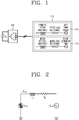
- FIG. 1 is a block diagram of a typical inverter system.
- an inverter system includes an inverter 100 and a plant 110.
- a current is generated in the inverter 100 and flows into the plant 110.
- the inverter 100 is configured as a power semiconductor switch such as an insulated gate bipolar mode transistor (IGBT) or a metal oxide silicon field effect transistor (MOSFET).
- the plant 110 may be configured as a grid-connected load 111 or a motor load 112.
- Both the grid-connected load 111 and the motor load 112 may be electrically configured in a form including an inductor component, a loss resistance component, and a voltage. That is, the grid-connected load 111 is electrically configured in the form including harmonic filter inductance, filter loss resistance, and a grid power source, and the motor load 112 is configured in the form including motor winding inductance, motor loss resistance, and counter electromotive force.
- FIG. 2 is an electric single-phase equivalent circuit diagram of FIG. 1 .
- an output current i s flows on the plant 110.
- the inductance component L s , the loss resistance component R s , and the voltage component V plant configure an equivalent circuit of the plant 110.
- FIGS. 3 and 4 are block diagrams of a current control apparatus according to various embodiments.
- a current control apparatus includes a first comparison unit 301, a transfer function application unit 302, an adding unit 303, a second comparison unit 304, and a calculation unit 305.
- the first comparison unit 301 outputs a current error i error between a current command i s * to be controlled and an output current i s actually applied to the plant 110.
- the transfer function application unit 302 outputs an output voltage V c by applying a first transfer function of a feedback component to the current error i error .
- the adding unit 303 outputs an inverter voltage V conv applied to the plant 110 by adding a feed-forward component V ff to the output voltage V c . At this time, the feed-forward component V ff is obtained by subtracting a measurement value from a voltage of a load. However, in the motor load 112, estimation other than the measurement is used.
- the second comparison unit 304 outputs a voltage error between the inverter voltage V conv and a plant voltage V plant .
- the calculation unit 305 outputs an output current i s applied to the plant 110 by applying a second transfer function, in which the inductance component L s and the loss resistance component R s of the plant 110 are expressed as a frequency domain, to an output of the second comparison unit 304.
- FIG. 3 shows a form without the feed-forward component V ff and the voltage component V plant of the plant 110.
- [Equation 1] is obtained.
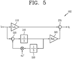
- FIG. 5 is a detailed configuration view of a transfer function application unit according to a first embodiment.
- a current control apparatus includes a transfer function application unit 502.
- the current control apparatus operates similar to a primary low-pass filter having a cut-off frequency ⁇ c .
- the transfer function application unit 502 applies a gain including the cut-off frequency ⁇ c to a current error i error .
- the transfer function application unit 502 includes a first applying portion 510, a first calculating portion 520, a second calculating portion 530, a first integrating portion 540, a second integrating portion 550, a second calculating portion 560 and a third calculating portion 570.
- the first applying portion 510 applies a first gain L s ⁇ c to a current error i error .
- the first gain L s ⁇ c is decided according to an inductance component L s of the plant 110 and a cut-off frequency ⁇ c .
- the first calculating portion 520 performs subtraction with respect to the current error i error .
- the first calculating portion 520 performs subtraction with respect to the current error i error by using an output of the second calculating portion 530.
- the first integrating portion 540 integrates the output of the first calculating portion 520.
- the second integrating portion 550 integrates an output of the first integrating portion 540.
- the second calculating portion 530 performs subtraction with respect to an output of the second integrating portion 550 by using a control frequency ⁇ ac of a current command.
- the second applying portion 560 applies a second gain R s ⁇ c to the output of the first integrating portion 540.
- the second gain R s ⁇ c is decided according to the loss resistance component R s of the plant 110 and the cut-off frequency ⁇ c .
- the third calculating portion 570 performs subtraction with respect to the output of the first applying portion 510 using the output of the second applying portion 560.
- the transfer function application unit 502 outputs an output voltage V c by applying a first transfer function C(s) as shown in the following [Equation 2] to the current error i error .
- a first gain corresponds to a first term of the first transfer function C(s)
- a second gain corresponds to a second term of the first transfer function C(s).
- Equation 4 expresses a characteristic of a primary low-pass filter having a cut-off frequency ⁇ c . According to [Equation 4], the current control apparatus operates like the primary low-pass filter having the cut-off frequency ⁇ c .
- the current control apparatus operates normally when the cut-off frequency ⁇ c can be designed to be sufficiently greater than the control frequency ⁇ ac .
- the cut-off frequency should be set to several kHz.
- the cut-off frequency ⁇ c is generally limited to a value smaller than a switching frequency of the inverter 100, there are a lot of limitations in such a harmonic control performance in a system operating at a switching frequency of 5 kHz or less.
- FIG. 6 is a configuration view of a current control apparatus in accordance with a second embodiment.
- a current control apparatus 600 includes a comparison unit 601, a transfer function application unit 602, and a calculation unit 603.
- the comparison unit 601 outputs a current error i error between a current command i s * and an output current i s of the plant 110.
- the transfer function application unit 602 outputs an output voltage V c by applying a first transfer function of a feedback component into the current error i error .
- the calculation unit 603 outputs an output current i s by applying a second transfer function to the output voltage V c .
- the second transfer function is decided based on an inductance component L s of the plant 110 and a loss resistance component R s of the plant 110.
- the current control apparatus 600 operates like a secondary band-pass filter, which uses a control frequency ⁇ ac of the current command as a center frequency, and a variable k represents a quality factor of the band-pass filter.
- the transfer function application unit 602 may apply the variable k and a gain, which includes the control frequency ⁇ ac of the current command to the current error i error .
- the transfer function application unit 602 includes a first applying portion 610, a first calculating portion 620, a second calculating portion 630, a first integrating portion 640, a second integrating portion 650, a second applying portion 660, a third calculating portion 670, a third applying portion 680, and a fourth calculating portion 690.
- the first applying portion 610 applies a first gain kL s ⁇ ac to the current error i error .
- the first gain kL s ⁇ ac is decided according to a variable k, the inductance component L s of the plant 110, and the control frequency ⁇ ac of the current command.
- the first calculating portion 620 performs subtraction with respect to the current error i error .
- the first calculating portion 620 performs subtraction with respect to the current error i error by using an output of the second calculating portion 630.
- the first integrating portion 640 integrates the output of the first calculating portion 620.
- the second integrating portion 650 integrates an output of the first integrating portion 640.
- the second calculating portion 630 performs multiplication with respect to an output of the second integrating portion 650 by using the control frequency ⁇ ac of the current command.
- the second applying portion 660 applies a second gain kR s ⁇ ac to the output of the first integrating portion 640.
- the second gain kR s ⁇ ac is decided according to the variable k, the loss resistance component R s of the plant 110, and the control frequency ⁇ ac of the current command.
- the third calculating portion 670 performs subtraction with respect to an output of the first applying portion 610 using an output of the second applying portion 660.
- the third applying portion 680 applies a third gain kL s ⁇ ac to the output of the second calculating portion 630.
- the third gain kL s ⁇ ac is decided based on the variable k, the inductance component L s of the plant 110 and the control frequency ⁇ ac of the current command.
- the fourth calculating portion 690 performs subtraction with respect to the output of the third calculating portion 670 using the output of the third applying portion 680. In this way, the fourth calculating portion 690 outputs an output voltage V c .
- the transfer function application unit 602 outputs the output voltage V c by applying the first transfer function C(s) as shown in the following [Equation 6] to the current error i error .
- the first gain corresponds to a first term of the first transfer function C(s)
- the second gain corresponds to a second term of the first transfer function C(s)
- the third gain corresponds to a third term of the first transfer function C(s).
- Equation 7 represents a characteristic of a secondary band-pass filter having the control frequency of the current command as the center frequency ⁇ ac and the variable k represents a quality factor of the band-pass filter.
- the current control apparatus 600 operates like the secondary band-pass filter having the control frequency ⁇ ac of the current command as the center frequency.
- the steady-state value becomes equal to A sin ⁇ ac t corresponding to the magnitude of the current command when a condition of ⁇ c ⁇ ac is satisfied.
- a feed-forward state value becomes equal to the current command without any condition.
- FIG. 7A is an exemplary view illustrating a response characteristic of the current control apparatus according to the first embodiment
- FIG. 7B is an exemplary view illustrating a response characteristic of the current control apparatus according to the second embodiment.
- FIG. 7A illustrates a bode diagram for [Equation 4], where an arrow direction indicates a direction in which the cut-off frequency ⁇ c is lowered. Due to the characteristic of the primary low-pass filter, the cut-off frequency ⁇ c cannot be designed sufficiently large. As a result, a controllable harmonic region decreases as the cut-off frequency ⁇ c is lowered (i.e., toward the arrow direction).
- FIG. 7B illustrates a bode diagram for [Equation 7], where an arrow direction indicates a direction in which the variable k decreases. Due to the characteristic of the secondary band-pass filter, the gain is 1 at the control frequency ⁇ c , irrespective of the variable k, and thus a steady-state performance is improved.
- the current control apparatus operates like the secondary band-pass filter
- the steady-state error is eliminated at the control frequency irrespective of the control variable. Therefore, even in a system having a low switching frequency, the harmonic current control performance can be effectively secured. Therefore, the harmonic control performance such as harmonic compensation or dead time compensation can be improved in an inverter system.
- an apparatus 600 for controlling an output current provided from an inverter 100 to a plant 110 according to a current command and a method thereof are provided.
- a current control apparatus 600 may include a comparison unit 601 for deciding a current error between a current command and an output current, a transfer function application unit 602 for outputting an output voltage by applying a gain including a control frequency of the current command to the current error, and a calculation unit 603 for outputting an output current from the output voltage.
- the current control apparatus 600 may operate like a secondary band-pass filter having a control frequency as a center frequency, so as to output the output current with the same magnitude as that of the current command in a steady state.
- the transfer function application unit 602 may output the output voltage by applying a first transfer function, which is decided based on a variable indicating a quality factor of the band-pass filter, a control frequency, an inductance component of the plant 110 and a loss resistance component of the plant 110, to the current error.
- the first transfer function may be decided by the following [Equation 9].
- C s k ⁇ ac L s + k ⁇ ac R s s 2 + ⁇ ac 2 s ⁇ kL s ⁇ ac 3 s 3 + ⁇ ac 2 (where k is the variable, ⁇ ac is the control frequency, L s is the inductance component, and R s is the loss resistance component.)
- the transfer function application unit 602 may include a first applying portion 610 that applies a first gain to the current error, which is decided based on the variable, the control frequency, and the inductance component of the plant 110.
- the transfer function application unit 602 may further include a first calculating portion 620 for performing subtraction with respect to the current error, a first integrating portion 640 for integrating an output of the first calculating portion 620, and a second integrating portion 660 for applying a second gain, which is decided based on the variable, the control frequency and the loss resistance component of the plant 110, to an output of the first integrating portion 640.
- the transfer function application unit 602 may further include a second integrating portion 650 for integrating the output of the first integrating portion 640, a second calculating portion 630 for performing multiplication with respect to an output of the second integrating portion 650, and a third applying portion 680 for applying a third gain, which is decided based on the variable, the control frequency, and the inductance component of the plant 110, to an output of the second calculating portion 630.
- the first calculating portion 620 may perform subtraction with respect to the current error using the output of the second integrating portion 650.
- the transfer function application unit 602 may further include a third calculating portion 670 for performing subtraction with respect to the output of the first applying portion 610 using the output of the second applying portion 660, and a fourth calculating portion 690 for performing subtraction with respect to an output of the third calculating portion 670 using the output of the third calculating portion 680 so as to output an output voltage.
- the calculation unit 603 may output an output current by applying a second transfer function, which is decided based on an inductance component and a loss resistance component of the plant 110, to the output voltage.
- a method of operating the current control apparatus 600 may include deciding a current error between a current command and an output current, outputting an output voltage by applying a gain including a control frequency of the current command to the current error, and outputting an output current from the output voltage.
Landscapes
- Engineering & Computer Science (AREA)
- Power Engineering (AREA)
- Physics & Mathematics (AREA)
- Electromagnetism (AREA)
- General Physics & Mathematics (AREA)
- Radar, Positioning & Navigation (AREA)
- Automation & Control Theory (AREA)
- Inverter Devices (AREA)
Abstract
Description
- Various embodiments relate to an apparatus and method for controlling current, and more particularly a proportional resonance (PR) control apparatus and an operating method thereof.
- Generally, a proportional and resonant (PR) control apparatus for controlling current is implemented on a stationary coordinate system of a single-phase or three-phase system to control alternating current, and is widely used in industry.
- Since the PR control apparatus theoretically has an infinite gain for a specific frequency, it has similar characteristics to those of a primary low-pass filter, in which a transfer function of a closed loop control system is a cut-off frequency. Therefore, if the cut-off frequency is designed to be sufficiently larger than a frequency of an AC signal to be controlled, a steady-state error is eliminated.
- However, the cut-off frequency of the closed loop control system cannot be infinitely increased because it is limited by a switching frequency of an inverter. Therefore, in an inverter with a low switching frequency, the steady-state error is caused with respect to a high frequency component upon a harmonic current compensation.
- Therefore, since the PR control apparatus is typically configured to compensate only for limited harmonic current, components over a specific frequency is uncontrollable.
- Various embodiments may provide an apparatus and method for controlling an output current provided from an inverter to a plant according to a current command.
- According to various embodiments, the apparatus may include a comparison unit to decide a current error between the current command and the output current, a transfer function application unit to output an output voltage by applying a gain including a control frequency of the current command to the current error, and a calculation unit to output the output current from the output voltage.
- According to various embodiments, the method may include deciding a current error between the current command and the output current, outputting an output voltage by applying a gain including a control frequency of the current command to the current error, and outputting the output current from the output voltage.
- According to various embodiments, since the apparatus is implemented as a secondary band-pass filter, an effect that a steady-state error is eliminated at the control frequency regardless of a control variable can be obtained. Therefore, an inverter system having a low switching frequency can effectively achieve a harmonic current control performance. Also, the inverter system can have an improved harmonic control performance such as harmonic compensation or dead time compensation.
-
-
FIG. 1 is a block diagram of a typical inverter system. -
FIG. 2 is an electric single-phase equivalent circuit diagram ofFIG. 1 . -
FIGS. 3 and 4 are block diagrams of a current control apparatus in accordance with various embodiments. -
FIG. 5 is a detailed configuration view of a transfer function application unit according to a first embodiment. -
FIG. 6 is a configuration view of a current control apparatus in accordance with a second embodiment. -
FIG. 7A is an exemplary view illustrating a response characteristic of the current control apparatus in accordance with the first embodiment, andFIG. 7B is an exemplary view illustrating a response characteristic of the current control apparatus in accordance with the second embodiment. - In order to fully understand the structure and effects of the present invention, the preferred embodiments of the present invention will be described with reference to the accompanying drawings. However, the present invention is not limited to the embodiments described below, but may be implemented in various forms modifications. The embodiments disclosed herein are merely illustrative to help understanding the present invention and fully inform of the scope of the present invention to those skilled in the art that the present invention pertains. In the accompanying drawings, constituent elements are enlarged in size for the convenience of explanation, and the proportions of the constituent elements may be exaggerated or reduced.
- It will be understood that when an element is referred to as being "on" or "in contact with" another element, the element is directly in contact with or is connected to the another element, or there are no intervening elements therebetween. It will be understood that when an element is referred to as being "directly on" or "directly in contact with" another element, there are no intervening elements present. Other expressions that describe the relationship among elements, for example, 'between' and 'directly between' may be similarly interpreted.
- It will be understood that although the terms first, second, etc. may be used herein to describe various elements, these elements should not be limited by these terms. These terms are generally only used to distinguish one element from another. For example, 'first component' may be referred to as 'second component', and similarly, the 'second component' may also be referred to as the 'first component', without departing from the scope of the present invention.
- A singular representation may include a plural representation unless it represents a definitely different meaning from the context. Terms such as "include" or "has" are used herein and should be understood that they are intended to indicate an existence of features, numbers, steps, functions, several components, or combinations thereof, disclosed in the specification, and it is also understood that greater or fewer features, numbers, steps, functions, several components, or combinations thereof may likewise be utilized.
- The terms used in the embodiments of the present invention may be construed as commonly known to those skilled in the art unless otherwise defined.
- Hereinafter, the present invention will be described in detail according to the preferred embodiments of the present invention with reference to the accompanying drawings.
-
FIG. 1 is a block diagram of a typical inverter system. - Referring to
FIG. 1 , an inverter system includes aninverter 100 and aplant 110. In the inverter system, a current is generated in theinverter 100 and flows into theplant 110. Theinverter 100 is configured as a power semiconductor switch such as an insulated gate bipolar mode transistor (IGBT) or a metal oxide silicon field effect transistor (MOSFET). Theplant 110 may be configured as a grid-connectedload 111 or amotor load 112. - Both the grid-connected
load 111 and themotor load 112 may be electrically configured in a form including an inductor component, a loss resistance component, and a voltage. That is, the grid-connectedload 111 is electrically configured in the form including harmonic filter inductance, filter loss resistance, and a grid power source, and themotor load 112 is configured in the form including motor winding inductance, motor loss resistance, and counter electromotive force. -
FIG. 2 is an electric single-phase equivalent circuit diagram ofFIG. 1 . - Referring to
FIG. 2 , as theinverter 100 generates a voltage Vconv , an output current is flows on theplant 110. The inductance component Ls , the loss resistance component Rs , and the voltage component Vplant configure an equivalent circuit of theplant 110. -
FIGS. 3 and 4 are block diagrams of a current control apparatus according to various embodiments. - Referring to
FIG. 3 , a current control apparatus includes afirst comparison unit 301, a transferfunction application unit 302, an addingunit 303, asecond comparison unit 304, and acalculation unit 305. - The
first comparison unit 301 outputs a current error ierror between a current command
plant 110. The transferfunction application unit 302 outputs an output voltage Vc by applying a first transfer function of a feedback component to the current error ierror. The addingunit 303 outputs an inverter voltage Vconv applied to theplant 110 by adding a feed-forward component Vff to the output voltage Vc . At this time, the feed-forward component Vff is obtained by subtracting a measurement value from a voltage of a load. However, in themotor load 112, estimation other than the measurement is used. Thesecond comparison unit 304 outputs a voltage error between the inverter voltage Vconv and a plant voltage Vplant. Thecalculation unit 305 outputs an output current is applied to theplant 110 by applying a second transfer function, in which the inductance component Ls and the loss resistance component Rs of theplant 110 are expressed as a frequency domain, to an output of thesecond comparison unit 304. - In
FIG. 3 , if the feed-forward component Vff is decided to be the same as the voltage component Vplant of theplant 110,FIG. 3 may be equated toFIG. 4 . That is,FIG. 3 shows a form without the feed-forward component Vff and the voltage component Vplant of theplant 110. A relation of the current of theplant 110 with respect to the current command on the basis of the form, the following [Equation 1] is obtained.
-
FIG. 5 is a detailed configuration view of a transfer function application unit according to a first embodiment. - Referring to
FIG. 5 , a current control apparatus according to a first embodiment includes a transferfunction application unit 502. At this time, the current control apparatus operates similar to a primary low-pass filter having a cut-off frequency ω c . At this time, the transferfunction application unit 502 applies a gain including the cut-off frequency ω c to a current error ierror. The transferfunction application unit 502 includes a first applyingportion 510, a first calculatingportion 520, a second calculating portion 530, a first integratingportion 540, a second integratingportion 550, a second calculatingportion 560 and a third calculatingportion 570. - The first applying
portion 510 applies a first gain Ls ω c to a current error ierror. At this time, the first gain Ls ω c is decided according to an inductance component Ls of theplant 110 and a cut-off frequency ω c . The first calculatingportion 520 performs subtraction with respect to the current error ierror. At this time, the first calculatingportion 520 performs subtraction with respect to the current error ierror by using an output of the second calculating portion 530. The first integratingportion 540 integrates the output of the first calculatingportion 520. The second integratingportion 550 integrates an output of the first integratingportion 540. The second calculating portion 530 performs subtraction with respect to an output of the second integratingportion 550 by using a control frequency ω ac of a current command. The second applyingportion 560 applies a second gain Rs ω c to the output of the first integratingportion 540. At this time, the second gain Rs ω c is decided according to the loss resistance component Rs of theplant 110 and the cut-off frequency ω c . The thirdcalculating portion 570 performs subtraction with respect to the output of the first applyingportion 510 using the output of the second applyingportion 560. - According to the first embodiment, the transfer
function application unit 502 outputs an output voltage Vc by applying a first transfer function C(s) as shown in the following [Equation 2] to the current error ierror. In [Equation 2], a first gain corresponds to a first term of the first transfer function C(s), and a second gain corresponds to a second term of the first transfer function C(s). By substituting [Equation 2] into [Equation 1], [Equation 3] below is obtained. At this time, when the value of Ls ω c is sufficiently greater than Rs (Lω c ≫Rs ), [Equation 3] is simplified to the following [Equation 4]. [Equation 4] expresses a characteristic of a primary low-pass filter having a cut-off frequency ω c . According to [Equation 4], the current control apparatus operates like the primary low-pass filter having the cut-off frequency ω c .


- Therefore, when a magnitude of the current command is A (that is, i*(s)=Asinω act), an output current controlled by using [Equation 4] is expressed within a time domain, and thus the following [Equation 5] may be obtained. In [Equation 5], a first term on a right side of i(t) is eliminated when a sufficient time elapses, and a second term on the right side of i(t) decides a steady-state value. According to the first embodiment, the steady-state value becomes the same as Asinω act corresponding to the magnitude of the current command when a condition of ω c ≫ω ac is satisfied. In other words, the current control apparatus operates normally when the cut-off frequency ω c can be designed to be sufficiently greater than the control frequency ω ac . For example, if a grid-connected inverter controls components of 300 Hz or 420 Hz to eliminate harmonic effects of a grid power source, the cut-off frequency should be set to several kHz.

- However, since the cut-off frequency ω c is generally limited to a value smaller than a switching frequency of the
inverter 100, there are a lot of limitations in such a harmonic control performance in a system operating at a switching frequency of 5 kHz or less. -
FIG. 6 is a configuration view of a current control apparatus in accordance with a second embodiment. - Referring to
FIG. 6 , acurrent control apparatus 600 according to a second embodiment includes acomparison unit 601, a transfer function application unit 602, and acalculation unit 603. Thecomparison unit 601 outputs a current error ierror between a current command
plant 110. The transfer function application unit 602 outputs an output voltage Vc by applying a first transfer function of a feedback component into the current error ierror. Thecalculation unit 603 outputs an output current is by applying a second transfer function to the output voltage Vc . The second transfer function is decided based on an inductance component Ls of theplant 110 and a loss resistance component Rs of theplant 110. - At this time, the
current control apparatus 600 operates like a secondary band-pass filter, which uses a control frequency ω ac of the current command as a center frequency, and a variable k represents a quality factor of the band-pass filter. According to the second embodiment, the transfer function application unit 602 may apply the variable k and a gain, which includes the control frequency ω ac of the current command to the current error ierror. - The transfer function application unit 602 includes a first applying
portion 610, a first calculatingportion 620, a second calculating portion 630, a first integratingportion 640, a second integratingportion 650, a second applyingportion 660, a third calculatingportion 670, a third applyingportion 680, and a fourth calculatingportion 690. - The first applying
portion 610 applies a first gain kLs ω ac to the current error ierror. At this time, the first gain kLs ω ac is decided according to a variable k, the inductance component Ls of theplant 110, and the control frequency ω ac of the current command. The first calculatingportion 620 performs subtraction with respect to the current error ierror. At this time, the first calculatingportion 620 performs subtraction with respect to the current error ierror by using an output of the second calculating portion 630. The first integratingportion 640 integrates the output of the first calculatingportion 620. The second integratingportion 650 integrates an output of the first integratingportion 640. The second calculating portion 630 performs multiplication with respect to an output of the second integratingportion 650 by using the control frequency ω ac of the current command. The second applyingportion 660 applies a second gain kRs ω ac to the output of the first integratingportion 640. At this time, the second gain kRs ω ac is decided according to the variable k, the loss resistance component Rs of theplant 110, and the control frequency ω ac of the current command. The thirdcalculating portion 670 performs subtraction with respect to an output of the first applyingportion 610 using an output of the second applyingportion 660. The third applyingportion 680 applies a third gain kLs ω ac to the output of the second calculating portion 630. At this time, the third gain kLs ω ac is decided based on the variable k, the inductance component Ls of theplant 110 and the control frequency ω ac of the current command. The fourth calculatingportion 690 performs subtraction with respect to the output of the third calculatingportion 670 using the output of the third applyingportion 680. In this way, the fourth calculatingportion 690 outputs an output voltage Vc . - According to the second embodiment, the transfer function application unit 602 outputs the output voltage Vc by applying the first transfer function C(s) as shown in the following [Equation 6] to the current error ierror. In [Equation 6], the first gain corresponds to a first term of the first transfer function C(s), the second gain corresponds to a second term of the first transfer function C(s), and the third gain corresponds to a third term of the first transfer function C(s). By substituting [Equation 6] into [Equation 1], the following [Equation 7] is obtained. [Equation 7] represents a characteristic of a secondary band-pass filter having the control frequency of the current command as the center frequency ω ac and the variable k represents a quality factor of the band-pass filter. According to [Equation 7], the
current control apparatus 600 operates like the secondary band-pass filter having the control frequency ω ac of the current command as the center frequency.

- Therefore, when a magnitude of the current command is A (that is, i*(s)=Asinω act), the output current controlled by using [Equation 7] is expressed in a time domain as expressed by [Equation 8] below. In [Equation 8], a first term of a right side of i(t) is eliminated when a sufficient time elapses, and a second term of the right side of i(t) decides a steady-state value. According to the second embodiment, the steady-state value is not affected by the variable factor, and always has the same magnitude as that of the current command. That is, according to the first embodiment, the steady-state value becomes equal to Asinω act corresponding to the magnitude of the current command when a condition of ω c ≫ω ac is satisfied. On the other hand, according to the second embodiment, a feed-forward state value becomes equal to the current command without any condition.

-
FIG. 7A is an exemplary view illustrating a response characteristic of the current control apparatus according to the first embodiment, andFIG. 7B is an exemplary view illustrating a response characteristic of the current control apparatus according to the second embodiment. -
FIG. 7A illustrates a bode diagram for [Equation 4], where an arrow direction indicates a direction in which the cut-off frequency ω c is lowered. Due to the characteristic of the primary low-pass filter, the cut-off frequency ω c cannot be designed sufficiently large. As a result, a controllable harmonic region decreases as the cut-off frequency ω c is lowered (i.e., toward the arrow direction). - On the other hand,
FIG. 7B illustrates a bode diagram for [Equation 7], where an arrow direction indicates a direction in which the variable k decreases. Due to the characteristic of the secondary band-pass filter, the gain is 1 at the control frequency ω c , irrespective of the variable k, and thus a steady-state performance is improved. - According to the second embodiment, as the current control apparatus operates like the secondary band-pass filter, the steady-state error is eliminated at the control frequency irrespective of the control variable. Therefore, even in a system having a low switching frequency, the harmonic current control performance can be effectively secured. Therefore, the harmonic control performance such as harmonic compensation or dead time compensation can be improved in an inverter system.
- According to various embodiments, an
apparatus 600 for controlling an output current provided from aninverter 100 to aplant 110 according to a current command and a method thereof are provided. - According to various embodiments, a
current control apparatus 600 may include acomparison unit 601 for deciding a current error between a current command and an output current, a transfer function application unit 602 for outputting an output voltage by applying a gain including a control frequency of the current command to the current error, and acalculation unit 603 for outputting an output current from the output voltage. - According to various embodiments, the
current control apparatus 600 may operate like a secondary band-pass filter having a control frequency as a center frequency, so as to output the output current with the same magnitude as that of the current command in a steady state. - According to various embodiments, the transfer function application unit 602 may output the output voltage by applying a first transfer function, which is decided based on a variable indicating a quality factor of the band-pass filter, a control frequency, an inductance component of the
plant 110 and a loss resistance component of theplant 110, to the current error. - According to various embodiments, the first transfer function may be decided by the following [Equation 9].

- According to various embodiments, the transfer function application unit 602 may include a first applying
portion 610 that applies a first gain to the current error, which is decided based on the variable, the control frequency, and the inductance component of theplant 110. - According to various embodiments, the transfer function application unit 602 may further include a first calculating
portion 620 for performing subtraction with respect to the current error, a first integratingportion 640 for integrating an output of the first calculatingportion 620, and a second integratingportion 660 for applying a second gain, which is decided based on the variable, the control frequency and the loss resistance component of theplant 110, to an output of the first integratingportion 640. - According to various embodiments, the transfer function application unit 602 may further include a second integrating
portion 650 for integrating the output of the first integratingportion 640, a second calculating portion 630 for performing multiplication with respect to an output of the second integratingportion 650, and a third applyingportion 680 for applying a third gain, which is decided based on the variable, the control frequency, and the inductance component of theplant 110, to an output of the second calculating portion 630. - According to various embodiments, the first calculating
portion 620 may perform subtraction with respect to the current error using the output of the second integratingportion 650. - According to various embodiments, the transfer function application unit 602 may further include a third calculating
portion 670 for performing subtraction with respect to the output of the first applyingportion 610 using the output of the second applyingportion 660, and a fourth calculatingportion 690 for performing subtraction with respect to an output of the third calculatingportion 670 using the output of the third calculatingportion 680 so as to output an output voltage. - According to various embodiments, the
calculation unit 603 may output an output current by applying a second transfer function, which is decided based on an inductance component and a loss resistance component of theplant 110, to the output voltage. - According to various embodiments, a method of operating the
current control apparatus 600 may include deciding a current error between a current command and an output current, outputting an output voltage by applying a gain including a control frequency of the current command to the current error, and outputting an output current from the output voltage. - The foregoing embodiments according to the present invention are merely illustrative, and it will be understood by those skilled in the art that various changes and modifications can be made without departing from the spirit and scope of the invention as defined by the appended claims. Therefore, the technical scope of the present invention should be determined by the following claims.
Claims (10)
- An apparatus (600) for controlling an output current provided from an inverter (100) to a plant (110) according to a current command, the apparatus comprising:a comparison unit (601) to decide a current error between the current command and the output current;a transfer function application unit (602) to output an output voltage by applying a gain including a control frequency of the current command to the current error; anda calculation unit (603) to output the output current from the output voltage.
- The apparatus of claim 1, wherein the calculation unit operates likes a secondary band-pass filter having the control frequency as a center frequency so as to output the output current in a manner of having the same magnitude as that of the current command in a steady state.
- The apparatus of claim 2, wherein the transfer function application unit (602) outputs the output voltage by applying a first transfer function to the current error, the first transfer function being decided based on a variable indicating a quality factor of the band-pass filter, the control frequency, an inductance component of the plant and a loss resistance component of the plant.
- The apparatus of claim 3, wherein the first transfer function is decided by the following equation,

- The apparatus of claim 3 or 4, wherein the transfer function application unit (602) comprises a first applying portion (610) to apply a first gain to the current error, the first gain being decided based on the variable, the control frequency and the inductance component of the plant (110).
- The apparatus of claim 5, wherein the transfer function application unit (602) further comprises:a first calculating portion (620) to perform subtraction with respect to the current error;a first integrating portion (640) to integrate an output of the first calculating portion (620); anda second applying portion (660) to apply a second gain to an output of the first integrating portion (640), the second gain being decided based on the variable, the control frequency and the loss resistance component of the plant (110).
- The apparatus of claim 6, wherein the transfer function application unit (602) comprises:a second integrating portion (650) to integrate the output of the first integrating portion (640);a second calculating portion (630) to perform multiplication with respect to an output of the second integrating portion (650) using the control frequency; anda third applying portion (680) to apply a third gain to an output of the second calculating portion (630), the third gain being decided based on the variable, the control frequency and the inductance component of the plant (110).
- The compressor of claim 7, wherein the first calculating portion (620) performs subtraction with respect to the current error using the output of the second integrating portion (650).
- The apparatus of claim 7 or 8, wherein the transfer function application unit (602) further comprises:a third calculating portion (630) to perform subtraction with respect to the output of the first applying portion (610) using the output of the second applying portion (660); anda fourth calculating portion (690) to perform subtraction with respect to an output of the third calculating portion (630) using an output of the third applying portion (680) so as to output the output voltage.
- The apparatus of any one of claims 1 to 9, wherein the calculation unit (603) outputs the output current by applying a second transfer function to the output voltage, the second transfer function being decided based on the inductance component of the plant (110) and the loss resistance component of the plant (110).
Applications Claiming Priority (1)
| Application Number | Priority Date | Filing Date | Title |
|---|---|---|---|
| KR1020170038962A KR20180109351A (en) | 2017-03-28 | 2017-03-28 | Proportional and resonant current controller |
Publications (1)
| Publication Number | Publication Date |
|---|---|
| EP3382878A1 true EP3382878A1 (en) | 2018-10-03 |
Family
ID=60452435
Family Applications (1)
| Application Number | Title | Priority Date | Filing Date |
|---|---|---|---|
| EP17203049.6A Withdrawn EP3382878A1 (en) | 2017-03-28 | 2017-11-22 | Apparatus and method for controlling current |
Country Status (5)
| Country | Link |
|---|---|
| US (1) | US10847334B2 (en) |
| EP (1) | EP3382878A1 (en) |
| JP (1) | JP6420453B2 (en) |
| KR (1) | KR20180109351A (en) |
| CN (1) | CN108664064B (en) |
Cited By (1)
| Publication number | Priority date | Publication date | Assignee | Title |
|---|---|---|---|---|
| CN112701941A (en) * | 2019-10-21 | 2021-04-23 | 广东美的白色家电技术创新中心有限公司 | Inverter compensation method and device, electrical equipment and storage medium |
Families Citing this family (1)
| Publication number | Priority date | Publication date | Assignee | Title |
|---|---|---|---|---|
| JP2024127547A (en) * | 2023-03-09 | 2024-09-20 | 株式会社Tmeic | BANDPASS FILTER, RESONANCE POINT DETECTOR, CONTROL DEVICE, AND CONTROL METHOD |
Citations (6)
| Publication number | Priority date | Publication date | Assignee | Title |
|---|---|---|---|---|
| WO2008103946A2 (en) * | 2007-02-22 | 2008-08-28 | Virginia Tech Intellectual Properties, Inc. | Control method for a universal power condition system |
| KR20130088440A (en) * | 2012-01-31 | 2013-08-08 | 울산대학교 산학협력단 | Control apparatus and method for power generator system |
| CN105610335A (en) * | 2015-12-31 | 2016-05-25 | 上海发电设备成套设计研究院 | Active damping control method of LCL grid-connected inverter under static coordinate |
| CN106230296A (en) * | 2016-08-05 | 2016-12-14 | 上海电机学院 | In grid-connected test power supply, method is analyzed in the control of inverter |
| US20160373025A1 (en) * | 2015-06-19 | 2016-12-22 | Sparq Systems Inc. | Adaptive control method for grid-connected inverters used with distributed power generation |
| US20170025943A1 (en) * | 2015-07-24 | 2017-01-26 | Suzan EREN | Method and apparatus for use with grid connected inverters in distributed power generation |
Family Cites Families (13)
| Publication number | Priority date | Publication date | Assignee | Title |
|---|---|---|---|---|
| JPH0720906A (en) * | 1993-07-06 | 1995-01-24 | Hitachi Ltd | Negative feedback control device and system using the same |
| US7026800B2 (en) | 2002-10-17 | 2006-04-11 | Richtek Technology Corp. | Feed-forward method for improving a transient response for a DC—DC power conversion and DC—DC voltage converter utilizing the same |
| JP2005269818A (en) | 2004-03-19 | 2005-09-29 | Fuji Electric Systems Co Ltd | Multi-phase AC current controller |
| JP4446286B2 (en) * | 2004-07-16 | 2010-04-07 | 有限会社シー・アンド・エス国際研究所 | Control method of controlled object with first-order lag characteristics |
| JP5217075B2 (en) * | 2004-10-30 | 2013-06-19 | 日本電産株式会社 | Single-phase AC signal phase detection method and power converter using the same method |
| DE102007036592B4 (en) * | 2007-08-02 | 2014-07-10 | Astrium Gmbh | High frequency generator for ion and electron sources |
| CN102075108B (en) * | 2011-01-20 | 2012-10-03 | 哈尔滨工业大学 | Capacitance current feedforward control method for grid-connected inverter with LCL filter |
| KR101761740B1 (en) * | 2011-02-01 | 2017-07-26 | 삼성전자 주식회사 | Apparatus for estimating inductance of permanent magnet synchronous motor and method the same |
| CN102185509A (en) * | 2011-05-26 | 2011-09-14 | 广东金华达电子有限公司 | Photovoltaic grid connected inverter output current control system |
| WO2013115240A1 (en) * | 2012-01-30 | 2013-08-08 | 三菱電機株式会社 | Motor control device |
| KR101566387B1 (en) | 2014-02-11 | 2015-11-05 | 주식회사 하이텍이피씨 | The apparatus for feed forward compensation in compensation of voltage-dip |
| US9319011B2 (en) | 2014-04-21 | 2016-04-19 | Taiwan Semiconductor Manufacturing Company, Ltd. | Class-D amplifier having mixed signal feedback control |
| CN104037800B (en) * | 2014-05-21 | 2016-01-20 | 中国科学院广州能源研究所 | A kind of photovoltaic combining inverter current control method |
-
2017
- 2017-03-28 KR KR1020170038962A patent/KR20180109351A/en not_active Ceased
- 2017-11-22 EP EP17203049.6A patent/EP3382878A1/en not_active Withdrawn
- 2017-12-14 CN CN201711338128.9A patent/CN108664064B/en not_active Expired - Fee Related
- 2017-12-21 JP JP2017245171A patent/JP6420453B2/en not_active Expired - Fee Related
-
2018
- 2018-01-03 US US15/861,307 patent/US10847334B2/en not_active Expired - Fee Related
Patent Citations (6)
| Publication number | Priority date | Publication date | Assignee | Title |
|---|---|---|---|---|
| WO2008103946A2 (en) * | 2007-02-22 | 2008-08-28 | Virginia Tech Intellectual Properties, Inc. | Control method for a universal power condition system |
| KR20130088440A (en) * | 2012-01-31 | 2013-08-08 | 울산대학교 산학협력단 | Control apparatus and method for power generator system |
| US20160373025A1 (en) * | 2015-06-19 | 2016-12-22 | Sparq Systems Inc. | Adaptive control method for grid-connected inverters used with distributed power generation |
| US20170025943A1 (en) * | 2015-07-24 | 2017-01-26 | Suzan EREN | Method and apparatus for use with grid connected inverters in distributed power generation |
| CN105610335A (en) * | 2015-12-31 | 2016-05-25 | 上海发电设备成套设计研究院 | Active damping control method of LCL grid-connected inverter under static coordinate |
| CN106230296A (en) * | 2016-08-05 | 2016-12-14 | 上海电机学院 | In grid-connected test power supply, method is analyzed in the control of inverter |
Non-Patent Citations (1)
| Title |
|---|
| GHOSHAL ANIRBAN ET AL: "A controller design method for 3 phase 4 wire grid connected VSI with LCL filter", SADHANA, INDIAN ACADEMY OF SCIENCES, BANGALORE, IN, vol. 40, no. 5, 7 September 2015 (2015-09-07), pages 1481 - 1499, XP035572167, ISSN: 0256-2499, [retrieved on 20150907], DOI: 10.1007/S12046-015-0393-3 * |
Cited By (1)
| Publication number | Priority date | Publication date | Assignee | Title |
|---|---|---|---|---|
| CN112701941A (en) * | 2019-10-21 | 2021-04-23 | 广东美的白色家电技术创新中心有限公司 | Inverter compensation method and device, electrical equipment and storage medium |
Also Published As
| Publication number | Publication date |
|---|---|
| CN108664064A (en) | 2018-10-16 |
| JP6420453B2 (en) | 2018-11-07 |
| CN108664064B (en) | 2020-05-19 |
| KR20180109351A (en) | 2018-10-08 |
| US10847334B2 (en) | 2020-11-24 |
| US20180286619A1 (en) | 2018-10-04 |
| JP2018166396A (en) | 2018-10-25 |
Similar Documents
| Publication | Publication Date | Title |
|---|---|---|
| US9722523B2 (en) | Inverter vector driving system and method for estimating capacitance using the same | |
| US10554137B2 (en) | DC/DC converter | |
| JP4737087B2 (en) | Control device for permanent magnet synchronous motor | |
| EP2472710B1 (en) | Power conversion device | |
| EP3068034B1 (en) | Alternating-current rotating machine controller | |
| EP1974444A2 (en) | Method and apparatus for controlling voltage linearity of voltage source inverters | |
| US10525838B2 (en) | Power conversion system | |
| JP6802126B2 (en) | Inverter controller | |
| KR20130041286A (en) | Motor controlling apparatus | |
| US8994317B2 (en) | Output control apparatus for electric motor and method for controlling output of electric motor | |
| US7791911B2 (en) | Inverter device which maintains voltage during input voltage drop | |
| CN112821373B (en) | Compensation device for leakage current | |
| US10547265B2 (en) | System and method for controlling motor | |
| CN103141022B (en) | Control device for inverter and inverter control method | |
| US10847334B2 (en) | Apparatus and method for controlling current | |
| KR20180075282A (en) | Apparatus for controlling dc link voltage in power cell of medium voltage inverter | |
| JP7463989B2 (en) | Motor Control Device | |
| CN113162417B (en) | DC conversion circuit, current ripple optimization method and vehicle-mounted charger | |
| CN113939995A (en) | Control device, inverter, assembly comprising an inverter and an electric machine, method for operating an inverter, and computer program | |
| JP2002044975A (en) | Induction motor control device | |
| US20240413767A1 (en) | Systems and methods for modulation index control of a dc-to-ac inverter | |
| TWI860592B (en) | Auxiliary power supply | |
| EP4520574A1 (en) | Vehicle power supply device | |
| US11916505B2 (en) | Method for operating a drive device for a motor vehicle, and corresponding drive device | |
| EP3782278B1 (en) | System and method for power conversion |
Legal Events
| Date | Code | Title | Description |
|---|---|---|---|
| PUAI | Public reference made under article 153(3) epc to a published international application that has entered the european phase |
Free format text: ORIGINAL CODE: 0009012 |
|
| STAA | Information on the status of an ep patent application or granted ep patent |
Free format text: STATUS: THE APPLICATION HAS BEEN PUBLISHED |
|
| AK | Designated contracting states |
Kind code of ref document: A1 Designated state(s): AL AT BE BG CH CY CZ DE DK EE ES FI FR GB GR HR HU IE IS IT LI LT LU LV MC MK MT NL NO PL PT RO RS SE SI SK SM TR |
|
| AX | Request for extension of the european patent |
Extension state: BA ME |
|
| STAA | Information on the status of an ep patent application or granted ep patent |
Free format text: STATUS: REQUEST FOR EXAMINATION WAS MADE |
|
| 17P | Request for examination filed |
Effective date: 20190403 |
|
| RBV | Designated contracting states (corrected) |
Designated state(s): AL AT BE BG CH CY CZ DE DK EE ES FI FR GB GR HR HU IE IS IT LI LT LU LV MC MK MT NL NO PL PT RO RS SE SI SK SM TR |
|
| GRAP | Despatch of communication of intention to grant a patent |
Free format text: ORIGINAL CODE: EPIDOSNIGR1 |
|
| STAA | Information on the status of an ep patent application or granted ep patent |
Free format text: STATUS: GRANT OF PATENT IS INTENDED |
|
| INTG | Intention to grant announced |
Effective date: 20210331 |
|
| STAA | Information on the status of an ep patent application or granted ep patent |
Free format text: STATUS: THE APPLICATION IS DEEMED TO BE WITHDRAWN |
|
| 18D | Application deemed to be withdrawn |
Effective date: 20210811 |