EP3382837A1 - A health monitoring system having a power converter controller for an electric machine - Google Patents
A health monitoring system having a power converter controller for an electric machine Download PDFInfo
- Publication number
- EP3382837A1 EP3382837A1 EP18162912.2A EP18162912A EP3382837A1 EP 3382837 A1 EP3382837 A1 EP 3382837A1 EP 18162912 A EP18162912 A EP 18162912A EP 3382837 A1 EP3382837 A1 EP 3382837A1
- Authority
- EP
- European Patent Office
- Prior art keywords
- power converter
- electric machine
- diagnostics
- health monitoring
- monitoring system
- Prior art date
- Legal status (The legal status is an assumption and is not a legal conclusion. Google has not performed a legal analysis and makes no representation as to the accuracy of the status listed.)
- Withdrawn
Links
Images



Classifications
-
- G—PHYSICS
- G05—CONTROLLING; REGULATING
- G05F—SYSTEMS FOR REGULATING ELECTRIC OR MAGNETIC VARIABLES
- G05F1/00—Automatic systems in which deviations of an electric quantity from one or more predetermined values are detected at the output of the system and fed back to a device within the system to restore the detected quantity to its predetermined value or values, i.e. retroactive systems
- G05F1/10—Regulating voltage or current
-
- G—PHYSICS
- G01—MEASURING; TESTING
- G01R—MEASURING ELECTRIC VARIABLES; MEASURING MAGNETIC VARIABLES
- G01R19/00—Arrangements for measuring currents or voltages or for indicating presence or sign thereof
- G01R19/003—Measuring mean values of current or voltage during a given time interval
-
- G—PHYSICS
- G01—MEASURING; TESTING
- G01R—MEASURING ELECTRIC VARIABLES; MEASURING MAGNETIC VARIABLES
- G01R19/00—Arrangements for measuring currents or voltages or for indicating presence or sign thereof
- G01R19/165—Indicating that current or voltage is either above or below a predetermined value or within or outside a predetermined range of values
- G01R19/17—Indicating that current or voltage is either above or below a predetermined value or within or outside a predetermined range of values giving an indication of the number of times this occurs, i.e. multi-channel analysers
-
- G—PHYSICS
- G01—MEASURING; TESTING
- G01R—MEASURING ELECTRIC VARIABLES; MEASURING MAGNETIC VARIABLES
- G01R19/00—Arrangements for measuring currents or voltages or for indicating presence or sign thereof
- G01R19/25—Arrangements for measuring currents or voltages or for indicating presence or sign thereof using digital measurement techniques
-
- G—PHYSICS
- G01—MEASURING; TESTING
- G01R—MEASURING ELECTRIC VARIABLES; MEASURING MAGNETIC VARIABLES
- G01R19/00—Arrangements for measuring currents or voltages or for indicating presence or sign thereof
- G01R19/25—Arrangements for measuring currents or voltages or for indicating presence or sign thereof using digital measurement techniques
- G01R19/2506—Arrangements for conditioning or analysing measured signals, e.g. for indicating peak values ; Details concerning sampling, digitizing or waveform capturing
-
- H—ELECTRICITY
- H02—GENERATION; CONVERSION OR DISTRIBUTION OF ELECTRIC POWER
- H02M—APPARATUS FOR CONVERSION BETWEEN AC AND AC, BETWEEN AC AND DC, OR BETWEEN DC AND DC, AND FOR USE WITH MAINS OR SIMILAR POWER SUPPLY SYSTEMS; CONVERSION OF DC OR AC INPUT POWER INTO SURGE OUTPUT POWER; CONTROL OR REGULATION THEREOF
- H02M3/00—Conversion of DC power input into DC power output
- H02M3/02—Conversion of DC power input into DC power output without intermediate conversion into AC
- H02M3/04—Conversion of DC power input into DC power output without intermediate conversion into AC by static converters
- H02M3/10—Conversion of DC power input into DC power output without intermediate conversion into AC by static converters using discharge tubes with control electrode or semiconductor devices with control electrode
- H02M3/145—Conversion of DC power input into DC power output without intermediate conversion into AC by static converters using discharge tubes with control electrode or semiconductor devices with control electrode using devices of a triode or transistor type requiring continuous application of a control signal
- H02M3/155—Conversion of DC power input into DC power output without intermediate conversion into AC by static converters using discharge tubes with control electrode or semiconductor devices with control electrode using devices of a triode or transistor type requiring continuous application of a control signal using semiconductor devices only
- H02M3/156—Conversion of DC power input into DC power output without intermediate conversion into AC by static converters using discharge tubes with control electrode or semiconductor devices with control electrode using devices of a triode or transistor type requiring continuous application of a control signal using semiconductor devices only with automatic control of output voltage or current, e.g. switching regulators
- H02M3/158—Conversion of DC power input into DC power output without intermediate conversion into AC by static converters using discharge tubes with control electrode or semiconductor devices with control electrode using devices of a triode or transistor type requiring continuous application of a control signal using semiconductor devices only with automatic control of output voltage or current, e.g. switching regulators including plural semiconductor devices as final control devices for a single load
- H02M3/1584—Conversion of DC power input into DC power output without intermediate conversion into AC by static converters using discharge tubes with control electrode or semiconductor devices with control electrode using devices of a triode or transistor type requiring continuous application of a control signal using semiconductor devices only with automatic control of output voltage or current, e.g. switching regulators including plural semiconductor devices as final control devices for a single load with a plurality of power processing stages connected in parallel
-
- H—ELECTRICITY
- H02—GENERATION; CONVERSION OR DISTRIBUTION OF ELECTRIC POWER
- H02P—CONTROL OR REGULATION OF ELECTRIC MOTORS, ELECTRIC GENERATORS OR DYNAMO-ELECTRIC CONVERTERS; CONTROLLING TRANSFORMERS, REACTORS OR CHOKE COILS
- H02P29/00—Arrangements for regulating or controlling electric motors, appropriate for both AC and DC motors
- H02P29/60—Controlling or determining the temperature of the motor or of the drive
-
- H—ELECTRICITY
- H02—GENERATION; CONVERSION OR DISTRIBUTION OF ELECTRIC POWER
- H02M—APPARATUS FOR CONVERSION BETWEEN AC AND AC, BETWEEN AC AND DC, OR BETWEEN DC AND DC, AND FOR USE WITH MAINS OR SIMILAR POWER SUPPLY SYSTEMS; CONVERSION OF DC OR AC INPUT POWER INTO SURGE OUTPUT POWER; CONTROL OR REGULATION THEREOF
- H02M1/00—Details of apparatus for conversion
- H02M1/0003—Details of control, feedback or regulation circuits
- H02M1/0025—Arrangements for modifying reference values, feedback values or error values in the control loop of a converter
Definitions
- the present invention relates generally to an electric converter controller for an electric machine.
- the present invention relates a health monitoring system including a power converter controller to determine performance and health status of the electric machine.
- a conventional electric machine health monitoring system is system 10, shown in FIG. 1 .
- the system 10 typically includes a power converter 12, and a power converter computing unit 20.
- the power converter computing unit 20 executes at least one software module including power converter control techniques.
- the system 10 further includes a separate, dedicated rotating machine monitoring and diagnostic unit 30 including a processing unit 32 executing at least one software module for monitoring and other diagnostic techniques for an electric machine 50.
- the system 10 also includes at least one sensor 40 and 42 for obtaining information, such as voltage and current measurements, of the electric machine 50 along with additional information e.g., temperature and vibration data to be used as input to the rotating machine monitoring and diagnostic unit 30.
- the power converter 12 obtains operational data including without limitation voltage and current measurements from at least one sensor which is separate from the sensors used by monitoring and diagnostic unit 30.
- the conventional system 10 requires a separate set of sensors and a separate computing unit 32 for performing the diagnostics for the electric machine 50. Therefore, this system 10 requires duplicate computing units and duplicate sensors which further increases hardware and development costs.
- a health monitoring system for an electric machine which includes a software module for diagnostic software techniques within the power converter system.
- these techniques can be performed and the health of an electric machine can be determined without any additional sensors, data acquisition, or computational processing hardware.
- a health monitoring system for an electric rotating machine includes a power converter which receives power from an electric power supply and which receives operational data from the electric rotating machine.
- the power converter contains at least one power converter computing unit and includes one or more software modules for performing control for the power converter and diagnostics of the electric rotating machine.
- a power converter in other embodiments of the present invention, includes at least one power converter computing unit having one or more software modules.
- the power converter receives power from an electric power supply and receives operational data from the electric machine via sensors in communication with the electric machine, and performs control of the power converter and diagnostics of the electric machine using the one or more software modules.
- the embodiments provide a health monitoring system that includes diagnostic techniques within the existing power converter that is already collecting the voltages and currents of the electric machine, these techniques can be run and the health of an electric machine can be determined without any additional sensor, data acquisition, or computational processing hardware.
- a method is further provided that includes using at least one sensor to perform control of the power converter and to obtain information for determining machine performance and health status, locally within the power converter.
- the health monitoring system according to one or more embodiments of the present invention will now be described with reference to FIGS. 2 and 3 .
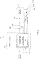
- FIG. 2 is a schematic of a health monitoring system 100 according to one or more embodiments of the present invention.
- the health monitoring system 100 includes a power converter 120 (e.g., an AC/AC, DC/AC, AC/DC or DC/DC power converter).
- the power converter 120 includes a power converter computing unit 130.
- the power converter computing unit 130 includes at least one software module 136 for performing control of the power converter 120 and also includes at least one software module 137 for performing diagnostics (e.g., health status and machine performance) of the electric machine 150.
- the power converter 120 can include a plurality of power converter computing units 130 each performing different power converter control algorithms and one or more software modules 137 for performing diagnostics of the electric machine 150.
- the power converter 120 receives power from an electric power supply and then supplies converted power to the electric machine 150 by a single bus 138 via at least one wire.
- the system 100 further includes sensors 200, 210 for obtaining operational information, such as voltage and current measurements, of the electric machine 150 along with additional sensors 212, 214 and 216 for diagnosing temperature and vibration data and insulation health of the electric machine 150.
- FIG. 3 shows a block diagram of a power converter computing unit 3000, which could be implemented as power converter computing unit 130.
- the power converter computing unit 3000 can include a processor 3020 that has a specific structure. The specific structure is imparted to the processor 3020 by instructions stored in a memory 3040 included therein and/or by instructions 3200 that can be fetched by the processor 3020 from a storage medium 3180.
- the storage medium 3180 may be co-located with computing unit 3000 as shown, or it maybe located elsewhere and be communicatively coupled to the computing unit 3000.
- the power converter computing unit 3000 is contained in the power converter system.
- the computing unit 3000 may include one or more hardware and/or software components configured to fetch, decode, execute, store, analyze, distribute, evaluate, diagnose, and/or categorize information. Furthermore, the computing unit 3000 can include an (input/output) I/O module 3140 that can be configured to interface with a plurality of remote devices including sensors.
- the processor 3020 may include one or more processing devices or cores (not shown). In some embodiments, the processor 3020 may be a plurality of processors, each having either one or more cores.
- the processor 3020 can be configured to execute instructions fetched from the memory 3040, i.e. from one of memory block 3120, memory block 3100, memory block 3080, or memory block 3060, or the instructions may be fetched from storage medium 3180, or from a remote device connected to computing unit 3000 via communication interface 3160.
- the storage medium 3180 and/or the memory 3040 may include a volatile or non-volatile, magnetic, semiconductor, tape, optical, removable, non-removable, read-only, random-access, or any type of non-transitory computer-readable computer medium.
- the storage medium 3180 and/or the memory 3040 may include programs and/or other information that may be used by the processor 3020.
- the storage medium 3180 may be configured to log data processed, recorded, or collected during the operation of the computing unit 3000.
- the storage medium 3180 may store historical patterns, predetermined thresholds, for each of the measurable variables associated with one or more electric machines coupled to the computing unit 3000.
- the data may be time-stamped, location-stamped, cataloged, indexed, or organized in a variety of ways consistent with data storage practice.
- the memory block 3060 may be a rotating machine monitoring and diagnostic module, and the memory block 3080 may be a power converter control algorithm module.
- the computing unit 3000 may fetch instructions from these modules, which, when executed by the processor 3020, cause the processor 3020 to perform certain operations.
- the operations may include receiving status data from an electric machine coupled to the computing unit 3000.
- the operations may further include using the status data to both perform a diagnostics test of the electric machine as well alter the control regimen of the power converter.
- the status data may include measured data associated with at least one of voltage and current of the electric machine.
- the diagnostics test may include comparing the status data with either a historical pattern or a predetermined threshold, or both, based on information stored in the storage medium 3180.
- a method 300 of FIG. 4 for performing health monitoring and machine performance of the electric machine 150 will now be discussed with reference to the health monitoring system 100 shown in FIGS. 2 and 3 .
- This method 300 leverages existing sensor data and processing capability that is already present to provide primary power converter control and to run diagnostic algorithms to determine electric machine performance and health status.
- the method begins at operation 310, where electric power is supplied to the electric machine via the power converter and the power converter computing unit receives operational data from the electric machine via at least one sensor in communication with the electric machine.
- the process continues to operation 320, where the operational data is transmitted to a data acquisition unit locally within the power converter computing unit. From operation 320, the process continues to operation 330 where the power converter is controlled using control algorithms within at least one software module executed by the power converter computing unit.
- the process continues where the operational data is further used to perform diagnostics of the electric machine using a software module having diagnostics algorithm to be implemented within the processor of the power converter computing unit.
- the operational data is used to both control the power converter and to perform diagnostics of the electric machine.
- the method 300 involves running additional software that can be added to one of the processors of the power converter computing unit, to passively run these diagnostic techniques using the operational data collected from the existing sensors. This eliminates the need for additional sensor hardware, data collection modules, data storage modules, and computational processing units.
- Fig. 5 is a flow diagram illustrating a method according to an alternative embodiment of the present invention. As shown in FIG. 5 , the method 400 starts at operation 410 where electric power is supplied to the electric machine via the power converter and the power converter computing unit receives operational data from the electric machine via at least one sensor in communication with the electric machine.
- the process continues to operation 420, where the power converter is controlled using control algorithms within at least one software module executed by the power converter computing unit.
- control algorithms performed simultaneously in serial arrangement in operations 430 and 440 respectively.
- Embodiments of the present invention provide advantages by leveraging existing hardware, simplifying the health monitoring system and reducing the total amount of control power consumption because a stand-alone diagnostic system is not employed.
Landscapes
- Engineering & Computer Science (AREA)
- Physics & Mathematics (AREA)
- General Physics & Mathematics (AREA)
- Power Engineering (AREA)
- Electromagnetism (AREA)
- Radar, Positioning & Navigation (AREA)
- Automation & Control Theory (AREA)
- Testing And Monitoring For Control Systems (AREA)
- Control Of Electric Motors In General (AREA)
Abstract
Description
- The present invention relates generally to an electric converter controller for an electric machine. In particular, the present invention relates a health monitoring system including a power converter controller to determine performance and health status of the electric machine.
- A conventional electric machine health monitoring system is
system 10, shown inFIG. 1 . Thesystem 10 typically includes apower converter 12, and a powerconverter computing unit 20. The powerconverter computing unit 20 executes at least one software module including power converter control techniques. Thesystem 10 further includes a separate, dedicated rotating machine monitoring anddiagnostic unit 30 including aprocessing unit 32 executing at least one software module for monitoring and other diagnostic techniques for anelectric machine 50. - The
system 10 also includes at least onesensor electric machine 50 along with additional information e.g., temperature and vibration data to be used as input to the rotating machine monitoring anddiagnostic unit 30. Thepower converter 12 obtains operational data including without limitation voltage and current measurements from at least one sensor which is separate from the sensors used by monitoring anddiagnostic unit 30. - The
conventional system 10 requires a separate set of sensors and aseparate computing unit 32 for performing the diagnostics for theelectric machine 50. Therefore, thissystem 10 requires duplicate computing units and duplicate sensors which further increases hardware and development costs. - Given the aforementioned deficiencies, there is a need for a health monitoring system for an electric machine which includes a software module for diagnostic software techniques within the power converter system. By embedding the software techniques inside the power converter system, these techniques can be performed and the health of an electric machine can be determined without any additional sensors, data acquisition, or computational processing hardware.
- In embodiments of the present invention, a health monitoring system for an electric rotating machine is provided. The health monitoring system includes a power converter which receives power from an electric power supply and which receives operational data from the electric rotating machine. The power converter contains at least one power converter computing unit and includes one or more software modules for performing control for the power converter and diagnostics of the electric rotating machine.
- In other embodiments of the present invention, a power converter is provided. The power converter includes at least one power converter computing unit having one or more software modules. The power converter receives power from an electric power supply and receives operational data from the electric machine via sensors in communication with the electric machine, and performs control of the power converter and diagnostics of the electric machine using the one or more software modules.
- The foregoing has broadly outlined some of the aspects and features of various embodiments, which should be construed to be merely illustrative of various potential applications of the disclosure. Other beneficial results can be obtained by applying the disclosed information in a different manner or by combining various aspects of the disclosed embodiments. Accordingly, other aspects and a more comprehensive understanding may be obtained by referring to the detailed description of the exemplary embodiments taken in conjunction with the accompanying drawings, in addition to the scope defined by the claims.
-
-
FIG. 1 is a schematic of a conventional health monitoring system for an electric machine. -
FIG. 2 is a schematic of a health monitoring system including a power converter for an electric machine that can be implemented within one or more embodiments of the present invention. -
FIG. 3 is a block diagram illustrating a power converter computing unit that can be implemented within one or more embodiments of the present invention. -
FIG. 4 is a flow diagram illustrating a method for performing health monitoring and machine performance of an electric machine that can be implemented within one or more embodiments of the present invention. -
FIG. 5 is a flow diagram illustrating a method for performing health monitoring and machine performance of an electric machine that can be implemented within one or more embodiments of the present invention. - The drawings are only for purposes of illustrating preferred embodiments and are not to be construed as limiting the disclosure. Given the following enabling description of the drawings, the novel aspects of the present disclosure should become evident to a person of ordinary skill in the art. This detailed description uses numerical and letter designations to refer to features in the drawings. Like or similar designations in the drawings and description have been used to refer to like or similar parts of embodiments of the invention.
- As required, detailed embodiments are disclosed herein. It must be understood that the disclosed embodiments are merely exemplary of various and alternative forms. As used herein, the word "exemplary" is used expansively to refer to embodiments that serve as illustrations, specimens, models, or patterns. The figures are not necessarily to scale and some features may be exaggerated or minimized to show details of particular components.
- In other instances, well-known components, apparatuses, materials, or methods that are known to those having ordinary skill in the art have not been described in detail in order to avoid obscuring the present disclosure. Therefore, specific structural and functional details disclosed herein are not to be interpreted as limiting, but merely as a basis for the claims and as a representative basis for teaching one skilled in the art.
- As noted above, the embodiments provide a health monitoring system that includes diagnostic techniques within the existing power converter that is already collecting the voltages and currents of the electric machine, these techniques can be run and the health of an electric machine can be determined without any additional sensor, data acquisition, or computational processing hardware. A method is further provided that includes using at least one sensor to perform control of the power converter and to obtain information for determining machine performance and health status, locally within the power converter.
- The health monitoring system according to one or more embodiments of the present invention will now be described with reference to
FIGS. 2 and3 . -
FIG. 2 is a schematic of ahealth monitoring system 100 according to one or more embodiments of the present invention. As shown, thehealth monitoring system 100 includes a power converter 120 (e.g., an AC/AC, DC/AC, AC/DC or DC/DC power converter). Thepower converter 120 includes a powerconverter computing unit 130. - The power
converter computing unit 130 includes at least onesoftware module 136 for performing control of thepower converter 120 and also includes at least onesoftware module 137 for performing diagnostics (e.g., health status and machine performance) of theelectric machine 150. According to one or more embodiments, thepower converter 120 can include a plurality of powerconverter computing units 130 each performing different power converter control algorithms and one ormore software modules 137 for performing diagnostics of theelectric machine 150. - The
power converter 120 receives power from an electric power supply and then supplies converted power to theelectric machine 150 by asingle bus 138 via at least one wire. Thesystem 100 further includessensors electric machine 150 along withadditional sensors electric machine 150. -
FIG. 3 shows a block diagram of a powerconverter computing unit 3000, which could be implemented as powerconverter computing unit 130. The powerconverter computing unit 3000 can include aprocessor 3020 that has a specific structure. The specific structure is imparted to theprocessor 3020 by instructions stored in amemory 3040 included therein and/or byinstructions 3200 that can be fetched by theprocessor 3020 from astorage medium 3180. Thestorage medium 3180 may be co-located withcomputing unit 3000 as shown, or it maybe located elsewhere and be communicatively coupled to thecomputing unit 3000. The powerconverter computing unit 3000 is contained in the power converter system. - The
computing unit 3000 may include one or more hardware and/or software components configured to fetch, decode, execute, store, analyze, distribute, evaluate, diagnose, and/or categorize information. Furthermore, thecomputing unit 3000 can include an (input/output) I/O module 3140 that can be configured to interface with a plurality of remote devices including sensors. - The
processor 3020 may include one or more processing devices or cores (not shown). In some embodiments, theprocessor 3020 may be a plurality of processors, each having either one or more cores. Theprocessor 3020 can be configured to execute instructions fetched from thememory 3040, i.e. from one ofmemory block 3120,memory block 3100,memory block 3080, ormemory block 3060, or the instructions may be fetched fromstorage medium 3180, or from a remote device connected tocomputing unit 3000 viacommunication interface 3160. - Furthermore, without loss of generality, the
storage medium 3180 and/or thememory 3040 may include a volatile or non-volatile, magnetic, semiconductor, tape, optical, removable, non-removable, read-only, random-access, or any type of non-transitory computer-readable computer medium. Thestorage medium 3180 and/or thememory 3040 may include programs and/or other information that may be used by theprocessor 3020. Moreover, thestorage medium 3180 may be configured to log data processed, recorded, or collected during the operation of thecomputing unit 3000. For example, thestorage medium 3180 may store historical patterns, predetermined thresholds, for each of the measurable variables associated with one or more electric machines coupled to thecomputing unit 3000. The data may be time-stamped, location-stamped, cataloged, indexed, or organized in a variety of ways consistent with data storage practice. - In one embodiment, for example, the
memory block 3060 may be a rotating machine monitoring and diagnostic module, and thememory block 3080 may be a power converter control algorithm module. As such, thecomputing unit 3000 may fetch instructions from these modules, which, when executed by theprocessor 3020, cause theprocessor 3020 to perform certain operations. - The operations may include receiving status data from an electric machine coupled to the
computing unit 3000. The operations may further include using the status data to both perform a diagnostics test of the electric machine as well alter the control regimen of the power converter. - The status data may include measured data associated with at least one of voltage and current of the electric machine. The diagnostics test may include comparing the status data with either a historical pattern or a predetermined threshold, or both, based on information stored in the
storage medium 3180. - A
method 300 ofFIG. 4 for performing health monitoring and machine performance of theelectric machine 150 will now be discussed with reference to thehealth monitoring system 100 shown inFIGS. 2 and3 . - This
method 300 leverages existing sensor data and processing capability that is already present to provide primary power converter control and to run diagnostic algorithms to determine electric machine performance and health status. The method begins atoperation 310, where electric power is supplied to the electric machine via the power converter and the power converter computing unit receives operational data from the electric machine via at least one sensor in communication with the electric machine. - From
operation 310, the process continues tooperation 320, where the operational data is transmitted to a data acquisition unit locally within the power converter computing unit. Fromoperation 320, the process continues tooperation 330 where the power converter is controlled using control algorithms within at least one software module executed by the power converter computing unit. - At
operation 340, the process continues where the operational data is further used to perform diagnostics of the electric machine using a software module having diagnostics algorithm to be implemented within the processor of the power converter computing unit. In thismethod 300, the operational data is used to both control the power converter and to perform diagnostics of the electric machine. - As discussed above, the
method 300 involves running additional software that can be added to one of the processors of the power converter computing unit, to passively run these diagnostic techniques using the operational data collected from the existing sensors. This eliminates the need for additional sensor hardware, data collection modules, data storage modules, and computational processing units. -
Fig. 5 is a flow diagram illustrating a method according to an alternative embodiment of the present invention. As shown inFIG. 5 , themethod 400 starts atoperation 410 where electric power is supplied to the electric machine via the power converter and the power converter computing unit receives operational data from the electric machine via at least one sensor in communication with the electric machine. - The process continues to
operation 420, where the power converter is controlled using control algorithms within at least one software module executed by the power converter computing unit. Followed by the diagnostic algorithms performed simultaneously in serial arrangement inoperations - Embodiments of the present invention provide advantages by leveraging existing hardware, simplifying the health monitoring system and reducing the total amount of control power consumption because a stand-alone diagnostic system is not employed.
- This written description uses examples to disclose the invention including the best mode, and also to enable any person skilled in the art to practice the invention, including making and using any devices or apparatuses and performing any incorporated methods. The patentable scope of the invention is defined by the claims, and may include other examples that occur to those skilled in the art. Such other examples are intended to be within the scope of the claims if they have structural elements that do not differ from the literal language of the claims, or if they include equivalent structural elements with insubstantial differences from the literal languages of the claims.
- Various aspects and embodiments of the present invention are defined by the following numbered clauses:
- 1. A power converter for an electric machine, the power converter comprising:
- at least power converter computing unit executing one or more software modules;
- wherein the power converter is configured to (i) receive power from an electric power supply, supply power to the electric machine, and (ii) receive operational data from the electric machine via sensors in communication with the electric machine, and (iii) perform control of the power converter and diagnostics of the electric machine using the one or more software modules.
- 2. The power converter of clause 1, comprising an AC/AC, DC/AC, DC/DC or AC/DC power converter.
- 3. The power converter of any preceding clause, wherein the at least one power converter computing unit contains at least one processor wherein each processor may include one or more processing devices or cores for performing the control of the power converter and the software module for performing the diagnostics of the electric machine, using the operational data received.
- 4. The power converter of any preceding clause, wherein a plurality of power converter computing units are networked and which execute both the power converter control algorithms and the electric machine monitoring and diagnostics algorithms.
- 5. The power converter of any preceding clause, wherein the sensors comprise at least one sensor for sensing temperature, insulation system information, vibration information, wherein the operational data comprises temperature, insulation system information, vibration information and current and voltage measurements of the electric machine.
Claims (9)
- A health monitoring system (100) for an electric machine (150), the health monitoring system (100) comprising:a power converter (120) configured to receive power from an electric power supply, to supply electric power to the electric machine (150), and to receive operational data from the electric machine (150);at least one power converter computing unit (130) disposed within the power converter (120) which executes one or more software modules (136, 137) for performing control for the power converter and diagnostics of the electric machine.
- The health monitoring system (100) of claim 1, wherein the power converter (120) comprises an AC/AC, DC/DC, AC/DC or DC/AC power converter.
- The health monitoring system (100) of claim 1 or 2, wherein the at least one power converter computing unit (130) contains at least one processor wherein each processor may include one or more processing devices or cores for performing the control of the power converter (120) and the software module for performing the diagnostics of the electric machine (150), using the operational data received from a plurality of sensors (200, 210, 212, 214, 216).
- The health monitoring system (100) of claim 3, wherein a plurality of power converter computing units (130) are networked and which execute both the power converter control algorithms (136) and the electric machine monitoring and diagnostics algorithms (137).
- The health monitoring system (100) of claim 3 or 4, wherein the sensors (200, 210, 212, 214 and 216) comprise at least one sensor for sensing temperature, insulation system information, vibration information, wherein the operational data comprises temperature, insulation system information, vibration information and current and voltage measurements of the electric machine (150).
- A method for performing diagnostics of an electric machine (150) via a health monitoring system (100), the method comprising:supplying electric power to a power converter (120) from an electric supply, supplying electric power to the electric machine (150) from the power converter (120), and receiving operational data from the electric machine (150) via sensors (200,210,212,214,216) in communication with the electric machine (150);transmitting the operational data to a data acquisition unit locally within the power converter (120);controlling the power converter (120) using control algorithms within one or more software modules (136,137) executed by at least one computing unit (130) of the power converter (120); andperforming diagnostics of the electric machine (150) using one or more software modules (136,137) having diagnostics algorithms to be executed by the at least one computing unit (130).
- The method of claim 6, further comprising:performing, by the at least one power converter computing unit (130) including at least one processor wherein each processor may include one or more processing devices or cores, control of the power converter (120) and the software module (136,137); andperforming the diagnostics of the electric machine (150), using the operational data received.
- The method of claim 6 or 7, wherein
networking a plurality of power converter computing units (130);
simultaneously executing power converter control algorithms and electric machine monitoring and diagnostics algorithms. - The method of claim 6, 7 or 8, further comprising:
sensing temperature, insulation system information, vibration information, wherein the operational data comprises temperature, insulation system information, vibration information and current and voltage measurements of the electric machine (150).
Applications Claiming Priority (1)
| Application Number | Priority Date | Filing Date | Title |
|---|---|---|---|
| US15/470,791 US20180275698A1 (en) | 2017-03-27 | 2017-03-27 | Health monitoring system having a power converter controller for an electric machine |
Publications (1)
| Publication Number | Publication Date |
|---|---|
| EP3382837A1 true EP3382837A1 (en) | 2018-10-03 |
Family
ID=61911341
Family Applications (1)
| Application Number | Title | Priority Date | Filing Date |
|---|---|---|---|
| EP18162912.2A Withdrawn EP3382837A1 (en) | 2017-03-27 | 2018-03-20 | A health monitoring system having a power converter controller for an electric machine |
Country Status (2)
| Country | Link |
|---|---|
| US (1) | US20180275698A1 (en) |
| EP (1) | EP3382837A1 (en) |
Families Citing this family (2)
| Publication number | Priority date | Publication date | Assignee | Title |
|---|---|---|---|---|
| CN110222399B (en) * | 2019-05-29 | 2022-12-09 | 中国电子产品可靠性与环境试验研究所((工业和信息化部电子第五研究所)(中国赛宝实验室)) | Power health assessment method and device |
| JP7524565B2 (en) * | 2020-03-18 | 2024-07-30 | 富士電機株式会社 | Power supply device and method for determining deterioration of power supply device |
Citations (6)
| Publication number | Priority date | Publication date | Assignee | Title |
|---|---|---|---|---|
| US20040263342A1 (en) * | 2003-06-30 | 2004-12-30 | Matlock Milton Gregory | System for monitoring motors |
| US20100169030A1 (en) * | 2007-05-24 | 2010-07-01 | Alexander George Parlos | Machine condition assessment through power distribution networks |
| US20100193267A1 (en) * | 2007-07-19 | 2010-08-05 | Toyota Jidosha Kabushiki Kaisha | Inverter control device and vehicle |
| US20120158012A1 (en) * | 2010-12-16 | 2012-06-21 | Sandhu Kulbir S | System and method of automatic detection and prevention of motor runaway |
| EP2679434A1 (en) * | 2011-02-25 | 2014-01-01 | NTN Corporation | Electric automobile, in-wheel motor drive device, and motor control method |
| US20140379156A1 (en) * | 2011-06-15 | 2014-12-25 | Expanergy, Llc | System and methods to wirelessly control distributed renewable energy on the grid or microgrid |
-
2017
- 2017-03-27 US US15/470,791 patent/US20180275698A1/en not_active Abandoned
-
2018
- 2018-03-20 EP EP18162912.2A patent/EP3382837A1/en not_active Withdrawn
Patent Citations (6)
| Publication number | Priority date | Publication date | Assignee | Title |
|---|---|---|---|---|
| US20040263342A1 (en) * | 2003-06-30 | 2004-12-30 | Matlock Milton Gregory | System for monitoring motors |
| US20100169030A1 (en) * | 2007-05-24 | 2010-07-01 | Alexander George Parlos | Machine condition assessment through power distribution networks |
| US20100193267A1 (en) * | 2007-07-19 | 2010-08-05 | Toyota Jidosha Kabushiki Kaisha | Inverter control device and vehicle |
| US20120158012A1 (en) * | 2010-12-16 | 2012-06-21 | Sandhu Kulbir S | System and method of automatic detection and prevention of motor runaway |
| EP2679434A1 (en) * | 2011-02-25 | 2014-01-01 | NTN Corporation | Electric automobile, in-wheel motor drive device, and motor control method |
| US20140379156A1 (en) * | 2011-06-15 | 2014-12-25 | Expanergy, Llc | System and methods to wirelessly control distributed renewable energy on the grid or microgrid |
Also Published As
| Publication number | Publication date |
|---|---|
| US20180275698A1 (en) | 2018-09-27 |
Similar Documents
| Publication | Publication Date | Title |
|---|---|---|
| CN112766342A (en) | Abnormity detection method for electrical equipment | |
| EP2725370B1 (en) | A method for the diagnostics of electromechanical system based on impedance analysis | |
| CN109948860A (en) | A kind of mechanical system method for predicting residual useful life and system | |
| CN116955895A (en) | Transformer operation abnormity monitoring method and system | |
| US11639966B2 (en) | Enhanced electrical signature analysis for fault detection | |
| RU2014105256A (en) | METHOD FOR MONITORING TECHNICAL CONDITION OF PIPELINE AND SYSTEM FOR ITS IMPLEMENTATION | |
| CN110441584A (en) | Equipment running state monitoring method, device, storage medium and system | |
| Pandarakone et al. | Frequency spectrum investigation and analytical diagnosis method for turn-to-turn short-circuit insulation failure in stator winding of low voltage induction motor | |
| US20180275698A1 (en) | Health monitoring system having a power converter controller for an electric machine | |
| US20140336988A1 (en) | Service module for a level measuring device and automated service method | |
| CN203881906U (en) | Smart alternating current load testing device | |
| CN111488947B (en) | Fault detection method and device for power system equipment | |
| US11366178B2 (en) | Method and system for diagnostics and monitoring of electric machines | |
| CN108377209A (en) | Equipment fault detecting system based on SCADA and detection method | |
| WO2025043679A1 (en) | State prediction method and apparatus for computer numerical control machine tool, electronic device, and medium | |
| EP3386055A2 (en) | Dynamic parameter limiting based on asset performance and health status | |
| CN119671533A (en) | A substation inspection method, device, terminal equipment and storage medium | |
| EP3376165B1 (en) | Power monitor | |
| CN111158342A (en) | Method for initializing and checking consistency of current sensor by motor controller | |
| CN114167270B (en) | A knife gate status recognition system based on edge computing | |
| CN118038353A (en) | Cable monitoring abnormality identification system and method based on image | |
| CN211123115U (en) | A device for evaluating electric field impact of motor slot insulation | |
| US10481968B2 (en) | Method and system for determining and reporting equipment operating conditions and health status | |
| CN119341012B (en) | A voltage regulating device and method for power distribution network equipment | |
| CN110285847A (en) | A kind of measurement auxiliary device and metering method of test macro |
Legal Events
| Date | Code | Title | Description |
|---|---|---|---|
| PUAI | Public reference made under article 153(3) epc to a published international application that has entered the european phase |
Free format text: ORIGINAL CODE: 0009012 |
|
| STAA | Information on the status of an ep patent application or granted ep patent |
Free format text: STATUS: THE APPLICATION HAS BEEN PUBLISHED |
|
| AK | Designated contracting states |
Kind code of ref document: A1 Designated state(s): AL AT BE BG CH CY CZ DE DK EE ES FI FR GB GR HR HU IE IS IT LI LT LU LV MC MK MT NL NO PL PT RO RS SE SI SK SM TR |
|
| AX | Request for extension of the european patent |
Extension state: BA ME |
|
| STAA | Information on the status of an ep patent application or granted ep patent |
Free format text: STATUS: REQUEST FOR EXAMINATION WAS MADE |
|
| 17P | Request for examination filed |
Effective date: 20190403 |
|
| RBV | Designated contracting states (corrected) |
Designated state(s): AL AT BE BG CH CY CZ DE DK EE ES FI FR GB GR HR HU IE IS IT LI LT LU LV MC MK MT NL NO PL PT RO RS SE SI SK SM TR |
|
| STAA | Information on the status of an ep patent application or granted ep patent |
Free format text: STATUS: EXAMINATION IS IN PROGRESS |
|
| 17Q | First examination report despatched |
Effective date: 20201103 |
|
| STAA | Information on the status of an ep patent application or granted ep patent |
Free format text: STATUS: THE APPLICATION IS DEEMED TO BE WITHDRAWN |
|
| 18D | Application deemed to be withdrawn |
Effective date: 20210515 |