EP3382831A1 - Wear protection feature for corona igniter - Google Patents
Wear protection feature for corona igniter Download PDFInfo
- Publication number
- EP3382831A1 EP3382831A1 EP18167224.7A EP18167224A EP3382831A1 EP 3382831 A1 EP3382831 A1 EP 3382831A1 EP 18167224 A EP18167224 A EP 18167224A EP 3382831 A1 EP3382831 A1 EP 3382831A1
- Authority
- EP
- European Patent Office
- Prior art keywords
- central
- crown
- corona igniter
- firing
- extended member
- Prior art date
- Legal status (The legal status is an assumption and is not a legal conclusion. Google has not performed a legal analysis and makes no representation as to the accuracy of the status listed.)
- Withdrawn
Links
Images




Classifications
-
- F—MECHANICAL ENGINEERING; LIGHTING; HEATING; WEAPONS; BLASTING
- F02—COMBUSTION ENGINES; HOT-GAS OR COMBUSTION-PRODUCT ENGINE PLANTS
- F02P—IGNITION, OTHER THAN COMPRESSION IGNITION, FOR INTERNAL-COMBUSTION ENGINES; TESTING OF IGNITION TIMING IN COMPRESSION-IGNITION ENGINES
- F02P23/00—Other ignition
- F02P23/04—Other physical ignition means, e.g. using laser rays
-
- H—ELECTRICITY
- H01—ELECTRIC ELEMENTS
- H01T—SPARK GAPS; OVERVOLTAGE ARRESTERS USING SPARK GAPS; SPARKING PLUGS; CORONA DEVICES; GENERATING IONS TO BE INTRODUCED INTO NON-ENCLOSED GASES
- H01T13/00—Sparking plugs
- H01T13/50—Sparking plugs having means for ionisation of gap
-
- H—ELECTRICITY
- H01—ELECTRIC ELEMENTS
- H01T—SPARK GAPS; OVERVOLTAGE ARRESTERS USING SPARK GAPS; SPARKING PLUGS; CORONA DEVICES; GENERATING IONS TO BE INTRODUCED INTO NON-ENCLOSED GASES
- H01T19/00—Devices providing for corona discharge
-
- H—ELECTRICITY
- H01—ELECTRIC ELEMENTS
- H01T—SPARK GAPS; OVERVOLTAGE ARRESTERS USING SPARK GAPS; SPARKING PLUGS; CORONA DEVICES; GENERATING IONS TO BE INTRODUCED INTO NON-ENCLOSED GASES
- H01T19/00—Devices providing for corona discharge
- H01T19/02—Corona rings
-
- H—ELECTRICITY
- H01—ELECTRIC ELEMENTS
- H01T—SPARK GAPS; OVERVOLTAGE ARRESTERS USING SPARK GAPS; SPARKING PLUGS; CORONA DEVICES; GENERATING IONS TO BE INTRODUCED INTO NON-ENCLOSED GASES
- H01T19/00—Devices providing for corona discharge
- H01T19/04—Devices providing for corona discharge having pointed electrodes
-
- H—ELECTRICITY
- H01—ELECTRIC ELEMENTS
- H01T—SPARK GAPS; OVERVOLTAGE ARRESTERS USING SPARK GAPS; SPARKING PLUGS; CORONA DEVICES; GENERATING IONS TO BE INTRODUCED INTO NON-ENCLOSED GASES
- H01T13/00—Sparking plugs
- H01T13/46—Sparking plugs having two or more spark gaps
- H01T13/467—Sparking plugs having two or more spark gaps in parallel connection
-
- H—ELECTRICITY
- H01—ELECTRIC ELEMENTS
- H01T—SPARK GAPS; OVERVOLTAGE ARRESTERS USING SPARK GAPS; SPARKING PLUGS; CORONA DEVICES; GENERATING IONS TO BE INTRODUCED INTO NON-ENCLOSED GASES
- H01T21/00—Apparatus or processes specially adapted for the manufacture or maintenance of spark gaps or sparking plugs
-
- H—ELECTRICITY
- H01—ELECTRIC ELEMENTS
- H01T—SPARK GAPS; OVERVOLTAGE ARRESTERS USING SPARK GAPS; SPARKING PLUGS; CORONA DEVICES; GENERATING IONS TO BE INTRODUCED INTO NON-ENCLOSED GASES
- H01T21/00—Apparatus or processes specially adapted for the manufacture or maintenance of spark gaps or sparking plugs
- H01T21/02—Apparatus or processes specially adapted for the manufacture or maintenance of spark gaps or sparking plugs of sparking plugs
-
- Y—GENERAL TAGGING OF NEW TECHNOLOGICAL DEVELOPMENTS; GENERAL TAGGING OF CROSS-SECTIONAL TECHNOLOGIES SPANNING OVER SEVERAL SECTIONS OF THE IPC; TECHNICAL SUBJECTS COVERED BY FORMER USPC CROSS-REFERENCE ART COLLECTIONS [XRACs] AND DIGESTS
- Y10—TECHNICAL SUBJECTS COVERED BY FORMER USPC
- Y10T—TECHNICAL SUBJECTS COVERED BY FORMER US CLASSIFICATION
- Y10T29/00—Metal working
- Y10T29/49—Method of mechanical manufacture
- Y10T29/49002—Electrical device making
Definitions
- This invention relates generally to a corona igniter for emitting a radio frequency electric field to ionize a fuel-air mixture and provide a corona discharge, a corona discharge ignition system, and methods of manufacturing the same.
- a corona igniter of a corona discharge ignition system receives a voltage from a power source and emits an electrical field that forms a corona to ionize a mixture of fuel and air of an internal combustion engine.
- the igniter includes an electrode extending longitudinally form an electrode terminal end to an electrode firing end.
- An insulator is disposed along the center electrode, and a shell is disposed along the insulator.
- the electrode terminal end receives the voltage from the power source and the electrode firing end emits the electrical field that forms the corona.
- the electrode of the corona igniter may also include a crown at the firing end for emitting the electrical field.
- the electrical field includes at least one streamer, and typically a plurality of streamers forming the corona. The mixture of air and fuel is ignited along the entire length of the high electrical field generated from the electrode firing end.
- An example of a corona igniter is disclosed in U.S. Patent Application Publication No. US 2010/0083942 to Lykowski et al.
- the corrosion and/or erosion of the metallic parts of the corona igniter in the combustion chamber is low since a corona discharge does not have the high current and high temperatures associated with the discharge of a conventional spark.
- the corona igniter does not include any grounded electrode element in close proximity to the firing tips of the crown, in some applications, there are grounded engine components that come close to the firing tips. Accordingly, it is not always possible to avoid an arc formation, also referred to as arcing, between the corona igniter and grounded component. If an arc forms, the high current and temperatures associated with the arc formation could cause some erosion and/or corrosion damage to the firing tips of the crown. Overtime, the erosion and/or corrosion damage could decrease the quality of corona formation and combustion.
- One aspect of the invention provides a corona igniter according to Claim 1.
- Another aspect of the invention provides a corona discharge ignition system including the corona igniter of Claim 1.
- Yet another aspect of the invention provides a method of manufacturing the corona igniter of Claim 1.
- the corona igniter including the central extended member with the extended length greater than the crown length provides several advantages over comparative corona igniters without the central extended member.
- a grounded component such as the piston
- the corona igniter comes close to the central firing end of the central extended member and the firing tips of the crown, if any arc forms, it will preferentially form between the piston and central firing end of the central extended member due to the extended length of the central extended member, its proximity to the grounded component, and hence its higher field strength, compared to the firing tips of the crown. Therefore, if arcing does occur, corrosion and erosion damage to the firing tips of the crown is reduced.
- the central extended member tends to repel the corona streamers as they form, thereby providing a wider volume of corona discharge and reducing the tendency of the corona discharge to approach the piston and form an arc.
- a corona igniter 20 including a central extended member 22 which is capable of providing improved corona discharge 24 and improved combustion performance is generally shown.
- the corona igniter 20 includes an electrode extending along a central axis A for emitting an electrical field that forms the corona discharge 24 .
- a shell 32 formed of a metal material is disposed around the insulator 28 .
- the electrode includes the central extended member 22 and a crown 34 .
- the crown 34 of the electrode is disposed outwardly of the insulator firing end 30 .
- the crown 34 surrounds the central axis A and the central extended member 22 .
- the crown 34 of the electrode also includes at least one branch 36 extending radially outwardly of the central extended member 22 , but typically includes a plurality of branches 36 each extending radially outwardly from the central axis A and radially outwardly of the central extended member 22 .
- the crown 34 includes four branches 36 spaced an equal distance from one another around the central axis A , as shown in Figure 1A .
- Each of the branches 36 presents a firing tip 38 for emitting the electrical field that forms the corona discharge 24 .
- the crown 34 presents a crown diameter D c disposed perpendicular to the central axis A .
- the crown diameter D c is the distance between two points of the crown 34 disposed directly opposite one another, such as the radially outermost points of two opposing firing tips 38 .
- the crown 34 extends along the central axis A from a top surface 40 to the at least one firing tip 38 .
- a crown length l c is thus presented between the top surface 40 and the at least one firing tip 38 .
- the crown length l c is parallel to the central axis A and it is equal to the distance between a first plane 42 and a second plane 44 each extending perpendicular to the central axis A .
- the first plane 42 is disposed at the uppermost point of the top surface 40 of the crown 34 and the second plane 44 is disposed at the lowermost point of the lowermost firing tip 38 .
- Each branch 36 of the crown 34 also presents at least one first spherical radius r 1 located at or adjacent to the associated firing tip 38 .
- Figure 1C shows a portion of the crown 34 of Figure 1B including two of the first spherical radii r 1 at the firing tip 38 of the crown 34 .
- a spherical radius at a particular point along a surface is obtained from a sphere having a radius at that particular point.
- the spherical radius is the radius of the sphere in three-dimensions, specifically along an x-axis, a y-axis, and a z-axis.
- the crown 34 can be formed of various different metal materials.
- the crown 34 is formed of nickel, nickel alloy, or a precious metal, such as platinum or iridium. Due to the central extended member 22 of the electrode, the material of the crown 34 can be formed of a less wear resistant material and experiences less corrosion and erosion if arcing occurs during operation of the corona igniter 20 .
- the central extended member 22 of the electrode extends longitudinally along the central axis A to a central firing end 46 .
- the central extended member 22 presents an extended length l e extending from the top surface 40 of the crown 34 to the central firing end 46 , as best shown in Figure 1B .
- the extended length l e is parallel to the central axis A and it is equal to the distance between the first plane 42 and a third plane 48 extending perpendicular to the central axis A .
- the first plane 42 is disposed at the uppermost point of the top surface 40 of the crown 34
- the third plane 48 is disposed at the lowermost point of the central firing end 46 .
- the extended length l e provided by the central extended member 22 is greater than the crown length l c .
- the central extended member 22 approaches a grounded component, such as the piston, more closely than the firing tips 38 of the crown 34 .
- a grounded component such as the piston
- the arcing will preferentially form from the central firing end 46 of the central extended member 22 , rather than from the firing tips 38 of the crown 34 .
- the extended length l e of the central extended member 22 can also increase the size of the corona discharge 24 formed by the electrode.
- the central extended member 22 presents at least one second spherical radius r 2 located at or adjacent to the central firing end 46 .
- Figure 1D shows a second spherical radius r 2 at the central firing end 46 .
- Each of the second spherical radii r 2 at or adjacent to the central firing end 46 of the central extended member 22 are less than each of the first spherical radii r 1 along the firing tips 38 of the crown 34 .
- the firing tips 38 of the crown 34 are sharper than the central firing end 46 . Therefore, during operation, the electric field is higher at the firing tips 38 of the crown 34 , and corona discharge 24 is more likely to form from the firing tips 38 than from the central extended member 22 , which is preferred for best combustion performance.
- the central extended member 22 presents an extended diameter D e disposed perpendicular to the central axis A .
- the extended diameter D e may vary along the central axis A , but in the area located between the crown 34 and the central firing end 46 , the extended diameter D e is less than the crown diameter D c .
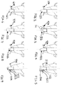
- Figures 2-11 illustrate other exemplary designs of the corona igniter 20 including the central extended member 22 .
- the designs may be selected to meet the requirements of the particular engine application and to provide the best possible thermal performance.
- the extended length l e of the central extended member 22 is greater than the crown length l c .
- each of the second spherical radii r 2 at or adjacent to the central firing end 46 of the central extended member 22 are greater than each of the first spherical radii r 1 at the firing tips 38 of the crown 34 .
- Figure 3A is an enlarged view of a portion of the design of Figure 3 , wherein the central extended member 322 includes a relatively small second spherical radius r 2 , but this second spherical radius r 2 is still greater than the first spherical radii r 1 of the crown 334 .
- the extended diameter D e of the central extended member 22 can decrease in a direction moving from the crown 34 toward the central firing end 46 , or increase in a direction moving from the crown 34 toward the central firing end 46 .
- the central extended member 22 does not need to be symmetrical.
- central extended member 22 Various different materials can be used to form the central extended member 22 , such as nickel, copper, precious metals, or alloys thereof. Portions of the central extended member 22 can also be formed of an insulating material.
- the central extended member 22 is typically formed of a first material and the crown 34 is typically formed of a second material different from the first material.
- the first material used to form the central extended member 22 is typically more resistant to erosion and corrosion than the second material used to form the crown 34 , since the central extended member 22 is more likely to be in contact with high current and temperature of the arc, if arcing does occur.
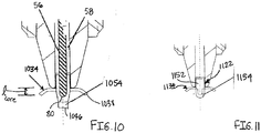
- the central extended member 22 is oftentimes formed of a plurality of separate pieces joined together, such as a body portion 52 and a wear element 54 , as shown in Figures 5, 9 , 10, and 11 .
- any of the shapes shown in Figures 2-11 could comprise a single piece, or a plurality of pieces joined together.
- the central extended member 522 includes a body portion 552 and a wear element 554 connected to one another.
- the wear element 554 is coaxial with the body portion 552 , but it does not need to be.
- the wear element 54 presents the central firing end 46 .
- the wear element 54 is typically formed of a material having good thermal characteristics and being more resistant to wear than the material of the body portion 52 .
- the wear element 54 is formed of a nickel-based alloy, a noble metal, or a precious metal, such as platinum, tungsten, or iridium.
- the wear element 54 is formed of an electrically insulating material preferably having a relative permittivity of greater than 2, and more preferably greater than 8, for example an alumina-based material.
- the wear element 54 can also comprise a coating of metal material or a coating of electrically insulating material.
- the wear element 54 may be applied to the body portion 52 of the central extended member 22 by any suitable means, for example PVD, co-extrusion, or co-sintering. Alternatively, the wear element 54 may be attached by brazing or a similar process. When the wear element 54 is a coating, the coating can be applied by plating, spraying, sintering, or another suitable method. The material of the body portion 52 and the material of the wear element 54 should be selected and joined to provide good bonding, no small gaps, good thermal contact, and to avoid problems with differential thermal expansion, for example.
- the central extended member 1022 in order to better withstand the effects of arc discharge, includes a core 56 formed of copper or a copper alloy, and the core 56 is surrounded by a cladding 58 formed of a nickel alloy.
- the wear element 1054 is attached to the cladding 58 and forms the central firing end 1046 .
- the cladding 58 of the nickel alloy could form the central firing end 1046 .
- the core 56 preferably has a core length l core extending from the top surface 1040 of the crown 1034 to a core firing end 80 .
- the core length l core is parallel to the central axis A and it is equal to the distance between the first plane 42 and a fourth plane 82 each extending perpendicular to the central axis A .
- the fourth plane 82 is disposed at the lowermost point of the core 56 .
- the core length l core is greater than the crown length l c .
- the cladding 58 of the central extended member 1022 still protects the copper core 56 . This design can significantly reduce the maximum temperature of the firing tips 1038 and can prolong the life of the firing tips 1038 and the central firing end 1046 .
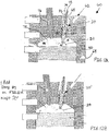
- FIG. 12A and 13A show a corona discharge ignition system 60 including the corona igniter 20 with the central extended member 22 to reduce corrosion and erosion at the firing tips 38 , as shown in Figures 12A and 13A .
- Figures 12B and 13B show s system with another type of corona igniter 20' , which does not include the extended length of the present invention.
- the system 60 includes components found in a conventional internal combustion engine, such as a cylinder head 62 , a cylinder block 64 , and a piston 50 .
- the piston 50 is disposed opposite the cylinder head 62 and presents a space therebetween, and the cylinder block 64 is connected to the cylinder head 62 and surrounds the piston 50 .
- the cylinder head 62 , cylinder block 64 , and piston 50 present a combustion chamber 66 therebetween.
- the cylinder head 62 presents an opening 68 for receiving the corona igniter 20 .
- the shell 32 of the corona igniter 20 is typically coupled to the cylinder head 62 , for example threaded into the opening 68 of the cylinder head 62 , as shown in Figures 12 and 13 .
- a gasket 70 is typically disposed between the shell 32 and the cylinder head 62 .
- the corona igniter 20 can include a terminal 72 for receiving the power from a power supply (now shown), and an insulation material 74 can be disposed between the terminal 72 and the electrode.
- a portion of the insulator 28 , as well as the central firing end 46 and the firing tips 38 are disposed in the combustion chamber 66 .
- a fuel injector 76 is also received in the cylinder head 62 for delivering fuel in the form of finely atomized spray 78 into the combustion chamber 66 .
- the piston 50 approaches the corona igniter 20 , 20' and arcing 25 does occur.
- the system 60 includes the inventive corona igniter 20 , such as in Figure 13A
- the arcing 25 does not occur from the firing tips 38 of the crown 34 , as it does when the comparative corona igniter 20' of Figure 13B is used. Rather, the arcing 25 occurs from the central firing end 46 of the central extension member 22 .
- the extended length l e of the central extended member 22 restricts the arcing 25 to only the central extended member 22 . Since the firing tips 38 of the crown 34 are less exposed to the high temperatures caused by the arcing 25 , they experience less corrosion and erosion. Thus, the firing tips 38 stay sharp and continue to provide a strong corona discharge 24 during future ignition cycles.
- the electrode of the corona igniter 20 of the present invention can also increase the size of the corona discharge 24 during operation.
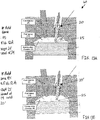
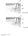
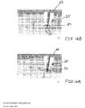
- Figures 14-16 each include a Finite Element Analysis (FEA) of an inventive corona igniter 20 or a comparative corona igniter 20' when power is supplied to the corona igniter 20 , 20' .
- the lines of the FEA images show the most likely direction and length of the corona discharge 24 .
- Figure 14A shows the inventive corona igniter 20 and associated corona discharge 24 when the piston 50 is spaced a significant distance from the central firing end 46 and firing tips 38 ;
- Figure 15A shows the inventive corona igniter 20 and the associated corona discharge 24 when the piston 50 is at the location of typical ignition;
- Figure 16A shows arcing 25 which occurs from the central firing end 46 of the inventive corona igniter 20 when the piston 50 comes very close to the corona igniter 20 .
- Figures 14B-16B each include a FEA of the corona discharge 24 provided by the comparative corona igniter 20' when the piston 50 is in the same positions as Figures 14A-16A .
- Figures 14A and 15A show that the corona igniter 20 of the present invention provides a stronger corona discharge 24 when the piston 50 is spaced from the corona igniter 20 , relative to the comparative corona igniter 20' of Figures 14B and 15B .
- the extended length l e of the central extended member 22 tends to repel the corona streamers as they form, thus providing a more open shape, giving a larger volume, and being less likely to encounter the piston 50 .
- Figure 16A shows that if arcing 25 occurs, the arcing will form from the central firing end 46 of the central extended member 22 , rather than from the firing tips 38 of the crown 34 . This is an advantage over the comparative corona igniter 20' of Figure 16B , wherein the arcing 25 forms from the firing tips 38' of the crown 34' .
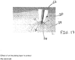
- Figure 17 is a FEA analysis of the inventive corona igniter 20 when the wear element 54 in the form of an insulating coating is applied over the central firing end 46 of the central extended member 22 . This analysis shows that the insulating coating does not detrimentally effect the operation of the corona igniter 20 or the benefits provided by the central extended member 22 .
- Another aspect of the invention provides a method of manufacturing the corona igniter 20 for use in the corona discharge ignition system 60 , which includes providing the central extended member 22 so that extended length l e of the central extended member 22 is greater than the crown length l c .
- the method first includes (a) identifying the firing tip 38 of the crown 34 which will be closest to the cylinder block 64 when the corona igniter 20 is received in the cylinder head 62 .
- method includes (b) determining a point during movement of the piston 50 where a distance from the firing tip 38 identified in step (a) to the cylinder block 64 is equal to a distance from the firing tip 38 identified in step (a) to the piston 50 .
- the method next includes (c) selecting the extended length l e of the central extended member 22 such that when power is provided to the electrode and when the firing tip 38 identified in step (a) is at the point identified in step (b), the peak electric field at the central firing end 46 of the central extended member 22 is equal to or greater than the peak electric field at the firing tip 38 identified in step (a).
- the peak electric field at the central firing end 46 of the central extended member 22 depends on the distance between the central firing end 46 and the piston 50 , and the distance between the central firing end 46 and the cylinder block 64 .
- the method can also include adjusting the extended length l e of the central extended member 22 to space the central firing end 46 of the central extended member 22 farther from the cylinder block 64 and/or the piston 50 during operation.
- the method also typically includes step (d): selecting the first spherical radii r 1 of the firing tips 38 and the second spherical radii r 2 of the central firing end 46 such that during operation, corona discharge will preferentially form from the firing tips 38 , and arcing, if any occurs, will preferentially form between the piston 50 and the central firing end 46 of the central extended member 22 .
- the step of selecting the spherical radii r 1 , r 2 can be conducted before or after selecting the extended length l e .
- the step of selecting the spherical radii r 1 , r 2 includes selecting the first spherical radii r 1 for each of the firing tips 38 of the crown 34 and selecting the second spherical radii r 2 for the central firing end 46 of the central extended member 22 such that each of the first spherical radii r 1 at the firing tips 38 of the crown 34 are smaller than the second spherical radii r 2 of the central extended member 22 .
- the spherical radii r 1 , r 2 are preferably selected so that when power is provided to the electrode, and the at least one firing tip 38 of the crown 34 and the central firing end 46 of the central extended member 22 are spaced from the cylinder block 64 and the piston 50 , and a corona discharge 24 is provided from the firing tips 38 , the peak electric field at the firing tip 38 closest to ground is at least 25% higher than the peak electric field at the central firing end 46 of the central extended member 22 .
- This may be achieved, for example, by using data of the form shown in Figure 18 .
- the first column of Figure 18 is the distance, in millimeters, from the central firing end 46 or the firing tip 38 to ground, also referred to as the gap to ground.
- the second column is the spherical radius, in millimeters, and it could be the spherical radius of either the central firing end 46 or the firing tip 38 .
- the third column is the peak electric field, in volts per meter, when 1 volt is applied.
- the values in Figure 18 are only examples. A dimensionless relationship between the spherical radii r 2 of the central firing end 46 of the central extended member 22 , the spherical radii r 1 of the firing tips 38 , and the extended length l e of the central extended member 22 could be obtained based on the data in Figure 18 .
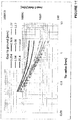
- Figure 19 is a graph providing the peak electric field for spherical radii ranging from about 0.05 mm to about 1.15 mm at various distances from the piston 50 and cylinder block 64 .
- Figure 19 specifically provides the peak electric field when the distance from the firing tip 38 to the piston 50 and to the cylinder block 64 is 0.254 mm, 0.508 mm, 1.27 mm, 2.54 mm, 5.08 mm, 12.7 mm, 24.5 mm, and 50.8 mm.
- the peak electric field at the firing tip 38 should be 25% higher than the peak electric field at the central firing end 46 of the central extended member 22 only at the larger distances, but this is not required at the shorter distances, for example only at 50.8 mm, but not at 0.254 mm.
- the method typically includes (e) determining the peak electric field of the firing tip 38 identified in step (a) at the distance identified in step (b).
- the data of Figure 18 can be used to determine this peak electric field.
- the firing tips 38 each have a spherical radius r 1 of 2.54 mm and a peak electric field of 330 V/m at a distance of 25.4 mm from the piston 50 .
- the method can further include adjusting the spherical radii r 1 , r 2 to meet all safety and operating conditions.
Landscapes
- Engineering & Computer Science (AREA)
- Physics & Mathematics (AREA)
- Plasma & Fusion (AREA)
- Optics & Photonics (AREA)
- Chemical & Material Sciences (AREA)
- Combustion & Propulsion (AREA)
- Mechanical Engineering (AREA)
- General Engineering & Computer Science (AREA)
- Spark Plugs (AREA)
- Ignition Installations For Internal Combustion Engines (AREA)
Abstract
Description
- This application claims priority to
U.S. Provisional Patent Application number 61/799,117, filed March 15, 2013 EP application no. 14722890.2 - This invention relates generally to a corona igniter for emitting a radio frequency electric field to ionize a fuel-air mixture and provide a corona discharge, a corona discharge ignition system, and methods of manufacturing the same.
- A corona igniter of a corona discharge ignition system receives a voltage from a power source and emits an electrical field that forms a corona to ionize a mixture of fuel and air of an internal combustion engine. The igniter includes an electrode extending longitudinally form an electrode terminal end to an electrode firing end. An insulator is disposed along the center electrode, and a shell is disposed along the insulator.
- The electrode terminal end receives the voltage from the power source and the electrode firing end emits the electrical field that forms the corona. The electrode of the corona igniter may also include a crown at the firing end for emitting the electrical field. The electrical field includes at least one streamer, and typically a plurality of streamers forming the corona. The mixture of air and fuel is ignited along the entire length of the high electrical field generated from the electrode firing end. An example of a corona igniter is disclosed in U.S. Patent Application Publication No.
US 2010/0083942 to Lykowski et al. - In an ideal corona ignition system, the corrosion and/or erosion of the metallic parts of the corona igniter in the combustion chamber is low since a corona discharge does not have the high current and high temperatures associated with the discharge of a conventional spark. Although the corona igniter does not include any grounded electrode element in close proximity to the firing tips of the crown, in some applications, there are grounded engine components that come close to the firing tips. Accordingly, it is not always possible to avoid an arc formation, also referred to as arcing, between the corona igniter and grounded component. If an arc forms, the high current and temperatures associated with the arc formation could cause some erosion and/or corrosion damage to the firing tips of the crown. Overtime, the erosion and/or corrosion damage could decrease the quality of corona formation and combustion.
- One aspect of the invention provides a corona igniter according to
Claim 1. - Another aspect of the invention provides a corona discharge ignition system including the corona igniter of
Claim 1. - Yet another aspect of the invention provides a method of manufacturing the corona igniter of
Claim 1. - According to additional aspects of the invention according to some dependent claims, the corona igniter including the central extended member with the extended length greater than the crown length provides several advantages over comparative corona igniters without the central extended member. When a grounded component, such as the piston, comes close to the central firing end of the central extended member and the firing tips of the crown, if any arc forms, it will preferentially form between the piston and central firing end of the central extended member due to the extended length of the central extended member, its proximity to the grounded component, and hence its higher field strength, compared to the firing tips of the crown. Therefore, if arcing does occur, corrosion and erosion damage to the firing tips of the crown is reduced.
- Furthermore, in situations where the grounded components are far from the corona igniter, the central extended member tends to repel the corona streamers as they form, thereby providing a wider volume of corona discharge and reducing the tendency of the corona discharge to approach the piston and form an arc.
- Other advantages of the present invention will be readily appreciated, as the same becomes better understood by reference to the following detailed description when considered in connection with the accompanying drawings wherein:
-
Figure 1 is a cross-sectional view of a portion of a corona igniter according to one exemplary embodiment of the invention; -
Figure 1A is a bottom view of a crown of the corona igniter ofFigure 1 ; -
Figure 1B is an enlarged view of a central extended member and the crown of the corona igniter ofFigure 1 ; -
Figure 1C is an enlarged view of a firing tip of the crown of the corona igniter ofFigure 1 showing a first spherical radius; -
Figure 1D is an enlarged view of a central firing end of the central extended member of the corona igniter ofFigure 1 showing a second spherical radius; -
Figures 2-11 are cross-sectional views of portions of corona igniters according to other exemplary embodiments of the invention; -
Figure 12A is a cross-sectional view of a corona discharge ignition system including the corona igniter ofFigure 1 when the corona igniter is spaced from a piston; -
Figure 12B is a cross-sectional view of the corona ignition system including a comparative corona igniter, without the central extended member of the present invention, when the comparative corona igniter is spaced from the piston by the same distance as the corona igniter ofFigure 12A ; -
Figure 13A is a cross-sectional view of the corona ignition system including the corona igniter ofFigure 1 when the corona igniter is close to the piston; -
Figure 13B is a cross-sectional view of the corona ignition system including the comparative corona igniter ofFigure 12B when the comparative corona igniter is in the same position as the corona igniter ofFigure 13A ; -
Figure 14A is a Finite Element Analysis (FEA) of a corona igniter according to another exemplary embodiment of the invention providing a corona discharge when the corona igniter is disposed a distance from a piston; -
Figure 14B is FEA of a comparative corona igniter providing a corona discharge when the comparative corona igniter is disposed the same distance from the piston as the corona igniter ofFigure 14A ; -
Figure 15A is a FEA of the corona igniter ofFigure 14A providing a corona discharge when the corona igniter is disposed at a typical location of ignition; -
Figure 15B is a FEA of the comparative corona igniter ofFigure 14B providing a corona discharge when the comparative corona igniter is disposed at the typical location of ignition; -
Figure 16A is a FEA of the corona igniter ofFigure 14A when the corona igniter is disposed closest to the piston, and wherein arcing occurs from the central extended member of the corona igniter; -
Figure 16B is a FEA of the comparative corona igniter ofFigure 14B when the comparative corona igniter is disposed at the same distance from the piston as the corona igniter ofFigure 16A , and wherein arcing occurs from the crown of the comparative corona igniter; -
Figure 17 is a FEA of the corona igniter ofFigure 14A when an insulating coating is applied to the central extended member; -
Figure 18 is a chart including exemplary data which can be used to obtain the peak electric field for a range of spherical radii at various distances from the piston and cylinder block; and -
Figure 19 is a graph providing the peak electric field for a range of spherical radii at various distances from the piston and cylinder block. - Referring to the Figures, wherein like numerals indicate corresponding parts throughout the several views, a
corona igniter 20 including a central extendedmember 22 which is capable of providing improvedcorona discharge 24 and improved combustion performance is generally shown. - As shown in
Figure 1 , thecorona igniter 20 includes an electrode extending along a central axis A for emitting an electrical field that forms thecorona discharge 24. As in conventional corona igniters, aninsulator 28 formed of an electrically insulating material, such as alumina, is disposed around the central extendedmember 22 and extends along the central axis A to aninsulator firing end 30. Ashell 32 formed of a metal material is disposed around theinsulator 28. The electrode includes the central extendedmember 22 and acrown 34. - The
crown 34 of the electrode is disposed outwardly of theinsulator firing end 30. Thecrown 34 surrounds the central axis A and the central extendedmember 22. Thecrown 34 of the electrode also includes at least onebranch 36 extending radially outwardly of the central extendedmember 22, but typically includes a plurality ofbranches 36 each extending radially outwardly from the central axis A and radially outwardly of the central extendedmember 22. In an exemplary embodiment, thecrown 34 includes fourbranches 36 spaced an equal distance from one another around the central axis A, as shown inFigure 1A . Each of thebranches 36 presents afiring tip 38 for emitting the electrical field that forms thecorona discharge 24. As best shown inFigure 1B , thecrown 34 presents a crown diameter Dc disposed perpendicular to the central axis A. The crown diameter Dc is the distance between two points of thecrown 34 disposed directly opposite one another, such as the radially outermost points of twoopposing firing tips 38. - Also shown in
Figure 1B , thecrown 34 extends along the central axis A from atop surface 40 to the at least onefiring tip 38. A crown length lc is thus presented between thetop surface 40 and the at least onefiring tip 38. As shown inFigure 1B , the crown length lc is parallel to the central axis A and it is equal to the distance between afirst plane 42 and asecond plane 44 each extending perpendicular to the central axis A. Thefirst plane 42 is disposed at the uppermost point of thetop surface 40 of thecrown 34 and thesecond plane 44 is disposed at the lowermost point of thelowermost firing tip 38. - Each
branch 36 of thecrown 34 also presents at least one first spherical radius r1 located at or adjacent to the associated firingtip 38.Figure 1C shows a portion of thecrown 34 ofFigure 1B including two of the first spherical radii r1 at thefiring tip 38 of thecrown 34. A spherical radius at a particular point along a surface is obtained from a sphere having a radius at that particular point. The spherical radius is the radius of the sphere in three-dimensions, specifically along an x-axis, a y-axis, and a z-axis. - The
crown 34 can be formed of various different metal materials. In one exemplary embodiment, thecrown 34 is formed of nickel, nickel alloy, or a precious metal, such as platinum or iridium. Due to the centralextended member 22 of the electrode, the material of thecrown 34 can be formed of a less wear resistant material and experiences less corrosion and erosion if arcing occurs during operation of thecorona igniter 20. - The central
extended member 22 of the electrode extends longitudinally along the central axis A to acentral firing end 46. The centralextended member 22 presents an extended length le extending from thetop surface 40 of thecrown 34 to thecentral firing end 46, as best shown inFigure 1B . The extended length le is parallel to the central axis A and it is equal to the distance between thefirst plane 42 and athird plane 48 extending perpendicular to the central axis A. Thefirst plane 42 is disposed at the uppermost point of thetop surface 40 of thecrown 34, and thethird plane 48 is disposed at the lowermost point of thecentral firing end 46. The extended length le provided by the centralextended member 22 is greater than the crown length lc . Due to the extended length le , during operation, the centralextended member 22 approaches a grounded component, such as the piston, more closely than the firingtips 38 of thecrown 34. Thus, if any arcing occurs during operation of thecorona igniter 20, the arcing will preferentially form from thecentral firing end 46 of the centralextended member 22, rather than from thefiring tips 38 of thecrown 34. The extended length le of the centralextended member 22 can also increase the size of thecorona discharge 24 formed by the electrode. - The central
extended member 22 presents at least one second spherical radius r2 located at or adjacent to thecentral firing end 46.Figure 1D shows a second spherical radius r2 at thecentral firing end 46. Each of the second spherical radii r2 at or adjacent to thecentral firing end 46 of the centralextended member 22 are less than each of the first spherical radii r1 along thefiring tips 38 of thecrown 34. In other words, thefiring tips 38 of thecrown 34 are sharper than thecentral firing end 46. Therefore, during operation, the electric field is higher at thefiring tips 38 of thecrown 34, andcorona discharge 24 is more likely to form from thefiring tips 38 than from the centralextended member 22, which is preferred for best combustion performance. - Also shown in
Figure 1B , the centralextended member 22 presents an extended diameter De disposed perpendicular to the central axis A. The extended diameter De may vary along the central axis A, but in the area located between thecrown 34 and thecentral firing end 46, the extended diameter De is less than the crown diameter Dc . -
Figures 2-11 illustrate other exemplary designs of thecorona igniter 20 including the centralextended member 22. The designs may be selected to meet the requirements of the particular engine application and to provide the best possible thermal performance. In each case, the extended length le of the centralextended member 22 is greater than the crown length l c. Also in each embodiment, each of the second spherical radii r2 at or adjacent to thecentral firing end 46 of the centralextended member 22 are greater than each of the first spherical radii r1 at thefiring tips 38 of thecrown 34.Figure 3A is an enlarged view of a portion of the design ofFigure 3 , wherein the centralextended member 322 includes a relatively small second spherical radius r2 , but this second spherical radius r2 is still greater than the first spherical radii r1 of the crown 334. In each design, the extended diameter De of the centralextended member 22 can decrease in a direction moving from thecrown 34 toward thecentral firing end 46, or increase in a direction moving from thecrown 34 toward thecentral firing end 46. In addition, the centralextended member 22 does not need to be symmetrical. - Various different materials can be used to form the central
extended member 22, such as nickel, copper, precious metals, or alloys thereof. Portions of the centralextended member 22 can also be formed of an insulating material. The centralextended member 22 is typically formed of a first material and thecrown 34 is typically formed of a second material different from the first material. The first material used to form the centralextended member 22 is typically more resistant to erosion and corrosion than the second material used to form thecrown 34, since the centralextended member 22 is more likely to be in contact with high current and temperature of the arc, if arcing does occur. - The central
extended member 22 is oftentimes formed of a plurality of separate pieces joined together, such as a body portion 52 and awear element 54, as shown inFigures 5, 9 ,10, and 11 . However, any of the shapes shown inFigures 2-11 could comprise a single piece, or a plurality of pieces joined together. For example, inFigure 5 the centralextended member 522 includes abody portion 552 and awear element 554 connected to one another. In this embodiment, thewear element 554 is coaxial with thebody portion 552, but it does not need to be. - In each embodiment, the
wear element 54 presents thecentral firing end 46. Thus, thewear element 54 is typically formed of a material having good thermal characteristics and being more resistant to wear than the material of the body portion 52. In one embodiment, thewear element 54 is formed of a nickel-based alloy, a noble metal, or a precious metal, such as platinum, tungsten, or iridium. In another embodiment, thewear element 54 is formed of an electrically insulating material preferably having a relative permittivity of greater than 2, and more preferably greater than 8, for example an alumina-based material. Thewear element 54 can also comprise a coating of metal material or a coating of electrically insulating material. - The
wear element 54 may be applied to the body portion 52 of the centralextended member 22 by any suitable means, for example PVD, co-extrusion, or co-sintering. Alternatively, thewear element 54 may be attached by brazing or a similar process. When thewear element 54 is a coating, the coating can be applied by plating, spraying, sintering, or another suitable method. The material of the body portion 52 and the material of thewear element 54 should be selected and joined to provide good bonding, no small gaps, good thermal contact, and to avoid problems with differential thermal expansion, for example. - In the embodiment of
Figure 10 , in order to better withstand the effects of arc discharge, the central extended member 1022 includes a core 56 formed of copper or a copper alloy, and thecore 56 is surrounded by acladding 58 formed of a nickel alloy. In the embodiment ofFigure 10 , thewear element 1054 is attached to thecladding 58 and forms thecentral firing end 1046. Alternatively, thecladding 58 of the nickel alloy could form thecentral firing end 1046. As shown inFigure 10 , the core 56 preferably has a core length lcore extending from the top surface 1040 of thecrown 1034 to acore firing end 80. The core length lcore is parallel to the central axis A and it is equal to the distance between thefirst plane 42 and a fourth plane 82 each extending perpendicular to the central axis A. The fourth plane 82 is disposed at the lowermost point of thecore 56. Preferably, the core length lcore is greater than the crown length l c. In this case, thecladding 58 of the central extended member 1022 still protects thecopper core 56. This design can significantly reduce the maximum temperature of thefiring tips 1038 and can prolong the life of thefiring tips 1038 and thecentral firing end 1046. - Another aspect of the invention provides a corona
discharge ignition system 60 including thecorona igniter 20 with the centralextended member 22 to reduce corrosion and erosion at thefiring tips 38, as shown inFigures 12A and13A . For comparison,Figures 12B and13B show s system with another type of corona igniter 20', which does not include the extended length of the present invention. Thesystem 60 includes components found in a conventional internal combustion engine, such as acylinder head 62, acylinder block 64, and apiston 50. Thepiston 50 is disposed opposite thecylinder head 62 and presents a space therebetween, and thecylinder block 64 is connected to thecylinder head 62 and surrounds thepiston 50. Thus, thecylinder head 62,cylinder block 64, andpiston 50 present acombustion chamber 66 therebetween. - The
cylinder head 62 presents anopening 68 for receiving thecorona igniter 20. Theshell 32 of thecorona igniter 20 is typically coupled to thecylinder head 62, for example threaded into theopening 68 of thecylinder head 62, as shown inFigures 12 and13 . Agasket 70 is typically disposed between theshell 32 and thecylinder head 62. Thecorona igniter 20 can include a terminal 72 for receiving the power from a power supply (now shown), and aninsulation material 74 can be disposed between the terminal 72 and the electrode. A portion of theinsulator 28, as well as thecentral firing end 46 and thefiring tips 38, are disposed in thecombustion chamber 66. A fuel injector 76 is also received in thecylinder head 62 for delivering fuel in the form of finely atomizedspray 78 into thecombustion chamber 66. - During operation, power is supplied to the
corona igniter 20, the fuel is sprayed toward thecorona igniter 20, and thepiston 50 reciprocates with thecylinder block 64, moving towards and away from thecylinder head 62 and thecorona igniter 20, as in a conventional corona ignition system. InFigure 12A , thepiston 50 is spaced from thecorona igniter 20 by a significant distance.Corona discharge 24 forms from thefiring tips 38 of thecrown 34, and no arc formation occurs between thecorona igniter 20 and thepiston 50 or any other grounded component. In thesystem 60 ofFigure 12B with the comparative corona igniter 20', thecorona discharge 24 is also formed without arc formation. - In
Figures 13A and 13B , however, thepiston 50 approaches thecorona igniter 20, 20' and arcing 25 does occur. When thesystem 60 includes theinventive corona igniter 20, such as inFigure 13A , the arcing 25 does not occur from thefiring tips 38 of thecrown 34, as it does when the comparative corona igniter 20' ofFigure 13B is used. Rather, the arcing 25 occurs from thecentral firing end 46 of thecentral extension member 22. The extended length le of the centralextended member 22 restricts the arcing 25 to only the centralextended member 22. Since thefiring tips 38 of thecrown 34 are less exposed to the high temperatures caused by the arcing 25, they experience less corrosion and erosion. Thus, thefiring tips 38 stay sharp and continue to provide astrong corona discharge 24 during future ignition cycles. - As mentioned above, the electrode of the
corona igniter 20 of the present invention can also increase the size of thecorona discharge 24 during operation.Figures 14-16 each include a Finite Element Analysis (FEA) of aninventive corona igniter 20 or a comparative corona igniter 20' when power is supplied to thecorona igniter 20, 20'. The lines of the FEA images show the most likely direction and length of thecorona discharge 24.Figure 14A shows theinventive corona igniter 20 and associatedcorona discharge 24 when thepiston 50 is spaced a significant distance from thecentral firing end 46 and firingtips 38;Figure 15A shows theinventive corona igniter 20 and the associatedcorona discharge 24 when thepiston 50 is at the location of typical ignition; andFigure 16A shows arcing 25 which occurs from thecentral firing end 46 of theinventive corona igniter 20 when thepiston 50 comes very close to thecorona igniter 20. For comparison,Figures 14B-16B each include a FEA of thecorona discharge 24 provided by the comparative corona igniter 20' when thepiston 50 is in the same positions asFigures 14A-16A . -
Figures 14A and15A show that thecorona igniter 20 of the present invention provides astronger corona discharge 24 when thepiston 50 is spaced from thecorona igniter 20, relative to the comparative corona igniter 20' ofFigures 14B and15B . The extended length le of the centralextended member 22 tends to repel the corona streamers as they form, thus providing a more open shape, giving a larger volume, and being less likely to encounter thepiston 50. In addition,Figure 16A shows that if arcing 25 occurs, the arcing will form from thecentral firing end 46 of the centralextended member 22, rather than from thefiring tips 38 of thecrown 34. This is an advantage over the comparative corona igniter 20' ofFigure 16B , wherein the arcing 25 forms from the firing tips 38' of the crown 34'. -
Figure 17 is a FEA analysis of theinventive corona igniter 20 when thewear element 54 in the form of an insulating coating is applied over thecentral firing end 46 of the centralextended member 22. This analysis shows that the insulating coating does not detrimentally effect the operation of thecorona igniter 20 or the benefits provided by the centralextended member 22. - Another aspect of the invention provides a method of manufacturing the
corona igniter 20 for use in the coronadischarge ignition system 60, which includes providing the centralextended member 22 so that extended length le of the centralextended member 22 is greater than the crown length l c. - Various techniques can be used to determine the appropriate extended length le of the central
extended member 22 in order to provide the preferred performance. In one embodiment, the method first includes (a) identifying thefiring tip 38 of thecrown 34 which will be closest to thecylinder block 64 when thecorona igniter 20 is received in thecylinder head 62. Next, then method includes (b) determining a point during movement of thepiston 50 where a distance from the firingtip 38 identified in step (a) to thecylinder block 64 is equal to a distance from the firingtip 38 identified in step (a) to thepiston 50. When thepiston 50 is located at this point, or closer to thefiring tips 38, there is a possibility of arcing between the firingtips 38 andpiston 50, but this possibility is mitigated by the centralextended member 22. - The method next includes (c) selecting the extended length le of the central
extended member 22 such that when power is provided to the electrode and when thefiring tip 38 identified in step (a) is at the point identified in step (b), the peak electric field at thecentral firing end 46 of the centralextended member 22 is equal to or greater than the peak electric field at thefiring tip 38 identified in step (a). The peak electric field at thecentral firing end 46 of the centralextended member 22 depends on the distance between thecentral firing end 46 and thepiston 50, and the distance between thecentral firing end 46 and thecylinder block 64. The method can also include adjusting the extended length le of the centralextended member 22 to space thecentral firing end 46 of the centralextended member 22 farther from thecylinder block 64 and/or thepiston 50 during operation. - The method also typically includes step (d): selecting the first spherical radii r1 of the
firing tips 38 and the second spherical radii r2 of thecentral firing end 46 such that during operation, corona discharge will preferentially form from thefiring tips 38, and arcing, if any occurs, will preferentially form between thepiston 50 and thecentral firing end 46 of the centralextended member 22. The step of selecting the spherical radii r1, r2 can be conducted before or after selecting the extended length le . The step of selecting the spherical radii r1, r2 includes selecting the first spherical radii r1 for each of thefiring tips 38 of thecrown 34 and selecting the second spherical radii r2 for thecentral firing end 46 of the centralextended member 22 such that each of the first spherical radii r1 at thefiring tips 38 of thecrown 34 are smaller than the second spherical radii r2 of the centralextended member 22. - The spherical radii r1, r2 are preferably selected so that when power is provided to the electrode, and the at least one
firing tip 38 of thecrown 34 and thecentral firing end 46 of the centralextended member 22 are spaced from thecylinder block 64 and thepiston 50, and acorona discharge 24 is provided from thefiring tips 38, the peak electric field at thefiring tip 38 closest to ground is at least 25% higher than the peak electric field at thecentral firing end 46 of the centralextended member 22. This may be achieved, for example, by using data of the form shown inFigure 18 . The first column ofFigure 18 is the distance, in millimeters, from thecentral firing end 46 or thefiring tip 38 to ground, also referred to as the gap to ground. The second column is the spherical radius, in millimeters, and it could be the spherical radius of either thecentral firing end 46 or thefiring tip 38. The third column is the peak electric field, in volts per meter, when 1 volt is applied. The values inFigure 18 are only examples. A dimensionless relationship between the spherical radii r2 of thecentral firing end 46 of the centralextended member 22, the spherical radii r1 of thefiring tips 38, and the extended length le of the centralextended member 22 could be obtained based on the data inFigure 18 . -
Figure 19 is a graph providing the peak electric field for spherical radii ranging from about 0.05 mm to about 1.15 mm at various distances from thepiston 50 andcylinder block 64.Figure 19 specifically provides the peak electric field when the distance from the firingtip 38 to thepiston 50 and to thecylinder block 64 is 0.254 mm, 0.508 mm, 1.27 mm, 2.54 mm, 5.08 mm, 12.7 mm, 24.5 mm, and 50.8 mm. The peak electric field at thefiring tip 38 should be 25% higher than the peak electric field at thecentral firing end 46 of the centralextended member 22 only at the larger distances, but this is not required at the shorter distances, for example only at 50.8 mm, but not at 0.254 mm. - Once the distance is identified in step (b), and the spherical radii r1, r2 are selected in step (d), the method typically includes (e) determining the peak electric field of the
firing tip 38 identified in step (a) at the distance identified in step (b). As an example again, the data ofFigure 18 can be used to determine this peak electric field. In one preferred embodiment, thefiring tips 38 each have a spherical radius r1 of 2.54 mm and a peak electric field of 330 V/m at a distance of 25.4 mm from thepiston 50. The method can further include adjusting the spherical radii r1, r2 to meet all safety and operating conditions. - Obviously, many modifications and variations of the present invention are possible in light of the above teachings and may be practiced otherwise than as specifically described while within the scope of the appended claims.
Claims (15)
- A corona igniter (20), comprising:an electrode extending along a central axis (A) for emitting an electrical field that forms a corona discharge;said electrode including a central extended member (22; 322; 522; 1022) extending longitudinally along said central axis (A) to a central firing end (46);an insulator (26) formed of an electrically insulating material disposed around said electrode and extending along said central axis (A) to an insulator firing end (30);a shell (32) formed of a metal material disposed around said insulator (26);said electrode including a crown (34; 334; 1034) disposed outwardly of said insulator firing end (30);said crown (34; 334; 1034) extending radially outwardly of said central extended member(22; 322; 522; 1022) to at least one firing tip (38); andsaid crown (34; 334; 1034) presenting at least one first spherical radius (r1) at each of said firing tips (38), said central extended member (22; 322; 522; 1022) presenting at least one second spherical radius (r2) at said central firing end (46), and each first spherical radius (r1) being smaller than each second spherical radius (r2).
- The corona igniter (20) of claim 1 wherein said crown (34; 334; 1034) includes a plurality of branches (36) each extending to one of said firing tips (38), each of said firing tips (38) having at least one of said first spherical radii (r1) each being smaller than each of said second spherical radii (r2).
- The corona igniter (20) of claim 1 wherein said central extended member (22; 322; 522; 1022) is formed of a first material and said crown (34; 334; 1034) is formed of a second material different from said first material, and said first material is more resistant to erosion and/or corrosion than said second material.
- The corona igniter (20) of claim 1 wherein said central extended member (22; 322; 522; 1022) includes a core (56) formed of copper or a copper alloy and a cladding (58) formed of a nickel alloy surrounding said core (56), and said cladding (58) of said central extended member (22; 322; 522; 1022) presents said central firing end (46).
- The corona igniter (20) of claim 4 wherein said core (56) has a core length (lcore) extending from said top surface (1040) of said crown (1034) to a core firing end (80), and said core length (lcore) is greater than said crown length (lc).
- The corona igniter (20) of claim 1 wherein said central extended member (22; 322; 522; 1022) includes a plurality of separate pieces joined together.
- The corona igniter (22) of claim 1 wherein said central extended member (522) includes a body portion (552) and a wear element (554) connected to one another, and said wear element (554) presents said central firing end (46).
- The corona igniter (20) of claim 7 wherein said wear element (554) is formed of one of a nickel-based alloy, a noble metal, a precious metal, a coating, or an electrically insulating material having a relative permittivity of greater than 2.
- The corona igniter (20) of claim 1, wherein said crown (34; 334; 1034) presents a crown length (lc) extending parallel to said central axis (A) between said top surface (40; 1040) and said at least one firing tip (38), said central extended member (22; 322; 522; 1022) presents an extended length (le) parallel to said central axis (A) and extending from said top surface (40; 1040) of said crown (34; 334; 1034) to said central firing end (46), said extended length (le) of said central extended member (22; 322; 522; 1022) being greater than said crown length (lc).
- The corona igniter (20) of claim 1 wherein said crown (34; 334; 1034) presents a crown diameter disposed perpendicular to said central axis (A), said central extended member (22; 322; 522; 1022) presents an extended diameter disposed perpendicular to said central axis (A), and said extended diameter is less than said crown diameter.
- The corona igniter (20) of claim 1 wherein said central extended member (22; 322; 522; 1022) presents an extended diameter disposed perpendicular to said central axis (A), and said extended diameter decreases in a direction moving from said crown (34; 334; 1034) toward said central firing end (46).
- The corona igniter of claim 1 wherein said central extended member (22; 322; 522; 1022) presents an extended diameter disposed perpendicular to said central axis (A), and said extended diameter increases in a direction moving from said crown (34; 334; 1034) toward said central firing end (46) .
- A corona discharge ignition system (60), comprising:a cylinder head (62) presenting an opening (68) for receiving a corona igniter (20);a piston (50) disposed opposite said cylinder head (62) and presenting a space therebetween;a cylinder block (64) connected to said cylinder head (62) and surrounding said piston (50);said cylinder head (62) and said cylinder block (64) and said piston (50) presenting a combustion chamber therebetween;a corona igniter (20) according to Claim 1 received in said opening (68) of said cylinder head (64).
- A method of manufacturing a corona igniter (20) for use in a corona discharge system (60) comprising the steps of:providing a corona igniter according to Claim 1; andselecting the at least one first spherical radius (r1) for the at least one firing tip (38) of the crown (34; 334; 1034) and selecting the at least one second spherical radius (r2) for the central firing end (46) of the central extended member (22; 322; 522; 1022) such that an electric field at at least one of the at least one firing tip (38) is higher than the electric field at the central firing end (46) of the central extended member (22; 322; 522; 1022) when power is provided to the electrode.
- The method of claim 14, wherein the crown (34; 334; 1034) presents a crown length (lc) extending parallel to the central axis (A) between the top surface (40; 1040) and the at least one firing tip (38), the central extended member (22; 322; 522; 1022) presents an extended length (le) parallel to the central axis (A) and extending from the top surface (40; 1040) of the crown (34; 334; 1034) to the central firing end (46), and the extended length of the central extended member (22; 322; 522; 1022) is greater than the crown length (lc).
Applications Claiming Priority (3)
| Application Number | Priority Date | Filing Date | Title |
|---|---|---|---|
| US201361799117P | 2013-03-15 | 2013-03-15 | |
| PCT/US2014/029902 WO2014145184A1 (en) | 2013-03-15 | 2014-03-15 | Wear protection feature for corona igniter |
| EP14722890.2A EP2973900B1 (en) | 2013-03-15 | 2014-03-15 | Wear protection feature for corona igniter |
Related Parent Applications (2)
| Application Number | Title | Priority Date | Filing Date |
|---|---|---|---|
| EP14722890.2A Division-Into EP2973900B1 (en) | 2013-03-15 | 2014-03-15 | Wear protection feature for corona igniter |
| EP14722890.2A Division EP2973900B1 (en) | 2013-03-15 | 2014-03-15 | Wear protection feature for corona igniter |
Publications (1)
| Publication Number | Publication Date |
|---|---|
| EP3382831A1 true EP3382831A1 (en) | 2018-10-03 |
Family
ID=50686176
Family Applications (2)
| Application Number | Title | Priority Date | Filing Date |
|---|---|---|---|
| EP18167224.7A Withdrawn EP3382831A1 (en) | 2013-03-15 | 2014-03-15 | Wear protection feature for corona igniter |
| EP14722890.2A Not-in-force EP2973900B1 (en) | 2013-03-15 | 2014-03-15 | Wear protection feature for corona igniter |
Family Applications After (1)
| Application Number | Title | Priority Date | Filing Date |
|---|---|---|---|
| EP14722890.2A Not-in-force EP2973900B1 (en) | 2013-03-15 | 2014-03-15 | Wear protection feature for corona igniter |
Country Status (7)
| Country | Link |
|---|---|
| US (1) | US9945347B2 (en) |
| EP (2) | EP3382831A1 (en) |
| JP (2) | JP6370877B2 (en) |
| KR (1) | KR20150129036A (en) |
| CN (2) | CN105164878B (en) |
| BR (1) | BR112015023085A8 (en) |
| WO (1) | WO2014145184A1 (en) |
Families Citing this family (6)
| Publication number | Priority date | Publication date | Assignee | Title |
|---|---|---|---|---|
| DE102012111190B3 (en) * | 2012-10-29 | 2014-04-30 | Borgwarner Beru Systems Gmbh | Corona ignition device and method for producing a firing head for a corona ignition device |
| BR112015023085A8 (en) * | 2013-03-15 | 2019-12-03 | Fed Mogul Ignition Co | Corona ignitor wear protection feature |
| DE102015116332B4 (en) * | 2015-09-28 | 2023-12-28 | Tdk Electronics Ag | Arrester, method of manufacturing the arrester and method of operating the arrester |
| DE102018105941B4 (en) | 2018-03-14 | 2021-09-02 | Federal-Mogul Ignition Gmbh | Spark plug ignition tip, spark plug assembly, and method of making a spark plug ignition tip |
| JP6943228B2 (en) * | 2018-09-03 | 2021-09-29 | マツダ株式会社 | Premixed compression ignition engine |
| JP6943229B2 (en) * | 2018-09-03 | 2021-09-29 | マツダ株式会社 | Premixed compression ignition engine |
Citations (5)
| Publication number | Priority date | Publication date | Assignee | Title |
|---|---|---|---|---|
| US20100083942A1 (en) | 2008-10-03 | 2010-04-08 | James Lykowski | Ignitor for air/fuel mixture and engine therewith and method of assembly thereof into a cylinder head |
| US20110247579A1 (en) * | 2010-04-13 | 2011-10-13 | Keith Hampton | Igniter including a corona enhancing electrode tip |
| US20120055434A1 (en) * | 2010-09-04 | 2012-03-08 | Borgwarner Beru Systems Gmbh | Igniter for igniting a fuel-air-mixture using hf corona discharge and engine fitted with such igniters |
| US20120199088A1 (en) * | 2010-12-14 | 2012-08-09 | John Antony Burrows | Corona ignition device having asymmetric firing tip |
| WO2014145184A1 (en) * | 2013-03-15 | 2014-09-18 | Federal-Mogul Ignition Company | Wear protection feature for corona igniter |
Family Cites Families (31)
| Publication number | Priority date | Publication date | Assignee | Title |
|---|---|---|---|---|
| US4227234A (en) * | 1978-07-03 | 1980-10-07 | Xerox Corporation | Corona charging element |
| US4402036A (en) | 1980-02-08 | 1983-08-30 | Hensley George H | Method of producing a high energy plasma for igniting fuel |
| US4774914A (en) | 1985-09-24 | 1988-10-04 | Combustion Electromagnetics, Inc. | Electromagnetic ignition--an ignition system producing a large size and intense capacitive and inductive spark with an intense electromagnetic field feeding the spark |
| US4841925A (en) * | 1986-12-22 | 1989-06-27 | Combustion Electromagnetics, Inc. | Enhanced flame ignition for hydrocarbon fuels |
| US5019709A (en) * | 1990-01-05 | 1991-05-28 | Pfaff Ernest H | Electrode arrangement for cheating corona |
| JP2847681B2 (en) * | 1991-12-03 | 1999-01-20 | 日本特殊陶業株式会社 | Method for manufacturing center electrode of spark plug |
| JP2853108B2 (en) * | 1992-06-17 | 1999-02-03 | 日本特殊陶業 株式会社 | Spark plug |
| US5488222A (en) * | 1994-09-16 | 1996-01-30 | Gault; Michael J. | Electrode arrangement for creating corona and method of treating electrically-conductive surfaces |
| US6608430B1 (en) | 2001-12-07 | 2003-08-19 | Robert J. Schaus | Spark plug with multi-point firing cap |
| US20040100179A1 (en) | 2002-11-25 | 2004-05-27 | Boley William C. | Spark plug having an encapsulated electrode gap |
| JP4924275B2 (en) | 2007-08-02 | 2012-04-25 | 日産自動車株式会社 | Non-equilibrium plasma discharge ignition system |
| US8104444B2 (en) | 2007-10-31 | 2012-01-31 | Caterpillar Inc. | Pre-chamber igniter having RF-aided spark initiation |
| DE102009059649B4 (en) * | 2009-12-19 | 2011-11-24 | Borgwarner Beru Systems Gmbh | HF ignition device |
| JP5375711B2 (en) * | 2010-03-30 | 2013-12-25 | 株式会社デンソー | Spark plug for internal combustion engine |
| EP2566000A1 (en) * | 2010-04-26 | 2013-03-06 | NGK Insulators, Ltd. | Ignition apparatus for internal combustion engine, and electrode structure for the ignition apparatus |
| US8701638B2 (en) * | 2010-05-07 | 2014-04-22 | Borgwarner Beru Systems Gmbh | Method for igniting a fuel-air mixture of a combustion chamber, particularly in an internal combustion engine by generating a corona discharge |
| EP2633593A2 (en) | 2010-10-28 | 2013-09-04 | Federal-Mogul Ignition Company | Non-thermal plasma ignition arc suppression |
| JP5887358B2 (en) * | 2010-12-29 | 2016-03-16 | フェデラル−モーグル・イグニション・カンパニーFederal−Mogul Ignition Company | Corona igniter with improved clearance control |
| WO2012097290A1 (en) * | 2011-01-13 | 2012-07-19 | Federal-Mogul Ignition Company | Corona igniter having controlled location of corona formation |
| CN102900586A (en) * | 2011-07-25 | 2013-01-30 | 何良智 | Integrated spark plug with multibank high pressure and multi-head ignition |
| WO2013028603A1 (en) * | 2011-08-19 | 2013-02-28 | Federal-Mogul Ignition Company | Corona igniter including temperature control features |
| US10056737B2 (en) * | 2012-03-23 | 2018-08-21 | Federal-Mogul Llc | Corona ignition device and assembly method |
| US10056738B2 (en) * | 2012-03-23 | 2018-08-21 | Federal-Mogul Llc | Corona ignition device with improved electrical performance |
| US9088136B2 (en) * | 2012-03-23 | 2015-07-21 | Federal-Mogul Ignition Company | Corona ignition device with improved electrical performance |
| EP3300193B1 (en) * | 2013-05-03 | 2020-10-07 | Federal-Mogul Ignition LLC | Corona ignition with hermetic combustion seal |
| US9484719B2 (en) * | 2014-07-11 | 2016-11-01 | Ming Zheng | Active-control resonant ignition system |
| US9685767B2 (en) * | 2014-08-10 | 2017-06-20 | Federal-Mogul Ignition Company | Corona ignition device with improved seal |
| KR20170041212A (en) * | 2014-08-10 | 2017-04-14 | 페더럴-모굴 이그니션 컴퍼니 | Corona ignition device with improved seal |
| US9755405B2 (en) * | 2015-03-26 | 2017-09-05 | Federal-Mogul Llc | Corona suppression at the high voltage joint through introduction of a semi-conductive sleeve between the central electrode and the dissimilar insulating materials |
| US9941671B2 (en) * | 2015-09-24 | 2018-04-10 | Federal-Mogul Llc | Air-free cap end design for corona ignition system |
| US10211605B2 (en) * | 2016-01-22 | 2019-02-19 | Tenneco Inc. | Corona igniter with hermetic combustion seal on insulator inner diameter |
-
2014
- 2014-03-15 BR BR112015023085A patent/BR112015023085A8/en not_active IP Right Cessation
- 2014-03-15 KR KR1020157029728A patent/KR20150129036A/en not_active Ceased
- 2014-03-15 JP JP2016503277A patent/JP6370877B2/en not_active Expired - Fee Related
- 2014-03-15 WO PCT/US2014/029902 patent/WO2014145184A1/en not_active Ceased
- 2014-03-15 EP EP18167224.7A patent/EP3382831A1/en not_active Withdrawn
- 2014-03-15 CN CN201480023216.8A patent/CN105164878B/en not_active Expired - Fee Related
- 2014-03-15 CN CN201710542762.8A patent/CN107453211B/en not_active Expired - Fee Related
- 2014-03-15 EP EP14722890.2A patent/EP2973900B1/en not_active Not-in-force
- 2014-03-17 US US14/215,540 patent/US9945347B2/en active Active
-
2018
- 2018-07-11 JP JP2018131614A patent/JP2018198209A/en not_active Ceased
Patent Citations (5)
| Publication number | Priority date | Publication date | Assignee | Title |
|---|---|---|---|---|
| US20100083942A1 (en) | 2008-10-03 | 2010-04-08 | James Lykowski | Ignitor for air/fuel mixture and engine therewith and method of assembly thereof into a cylinder head |
| US20110247579A1 (en) * | 2010-04-13 | 2011-10-13 | Keith Hampton | Igniter including a corona enhancing electrode tip |
| US20120055434A1 (en) * | 2010-09-04 | 2012-03-08 | Borgwarner Beru Systems Gmbh | Igniter for igniting a fuel-air-mixture using hf corona discharge and engine fitted with such igniters |
| US20120199088A1 (en) * | 2010-12-14 | 2012-08-09 | John Antony Burrows | Corona ignition device having asymmetric firing tip |
| WO2014145184A1 (en) * | 2013-03-15 | 2014-09-18 | Federal-Mogul Ignition Company | Wear protection feature for corona igniter |
Also Published As
| Publication number | Publication date |
|---|---|
| KR20150129036A (en) | 2015-11-18 |
| US20140261270A1 (en) | 2014-09-18 |
| JP2018198209A (en) | 2018-12-13 |
| EP2973900B1 (en) | 2018-12-19 |
| CN105164878B (en) | 2017-07-28 |
| CN107453211A (en) | 2017-12-08 |
| CN105164878A (en) | 2015-12-16 |
| WO2014145184A1 (en) | 2014-09-18 |
| CN107453211B (en) | 2019-06-14 |
| BR112015023085A2 (en) | 2017-07-18 |
| EP2973900A1 (en) | 2016-01-20 |
| JP6370877B2 (en) | 2018-08-15 |
| US9945347B2 (en) | 2018-04-17 |
| JP2016519391A (en) | 2016-06-30 |
| BR112015023085A8 (en) | 2019-12-03 |
Similar Documents
| Publication | Publication Date | Title |
|---|---|---|
| EP2973900B1 (en) | Wear protection feature for corona igniter | |
| US9010294B2 (en) | Corona igniter including temperature control features | |
| CN101496239B (en) | Small diameter/long reach spark plug with improved insulator design | |
| EP2724430B2 (en) | Corona igniter assembly including corona enhancing insulator geometry | |
| US20160359301A1 (en) | Corona ignition device and assembly method | |
| JP4829892B2 (en) | Coaxial twin spark plug | |
| US10784655B2 (en) | Corona igniter with hermetic combustion seal on insulator inner diameter | |
| EP3338332B1 (en) | Corona ignition device and assembly method | |
| CN111247707A (en) | Electrode head of corona igniter ignition end with bimetal rivet and its manufacturing method | |
| US20170025821A1 (en) | Spark plug |
Legal Events
| Date | Code | Title | Description |
|---|---|---|---|
| PUAI | Public reference made under article 153(3) epc to a published international application that has entered the european phase |
Free format text: ORIGINAL CODE: 0009012 |
|
| STAA | Information on the status of an ep patent application or granted ep patent |
Free format text: STATUS: THE APPLICATION HAS BEEN PUBLISHED |
|
| AC | Divisional application: reference to earlier application |
Ref document number: 2973900 Country of ref document: EP Kind code of ref document: P |
|
| AK | Designated contracting states |
Kind code of ref document: A1 Designated state(s): AL AT BE BG CH CY CZ DE DK EE ES FI FR GB GR HR HU IE IS IT LI LT LU LV MC MK MT NL NO PL PT RO RS SE SI SK SM TR |
|
| STAA | Information on the status of an ep patent application or granted ep patent |
Free format text: STATUS: REQUEST FOR EXAMINATION WAS MADE |
|
| 17P | Request for examination filed |
Effective date: 20181203 |
|
| RBV | Designated contracting states (corrected) |
Designated state(s): AL AT BE BG CH CY CZ DE DK EE ES FI FR GB GR HR HU IE IS IT LI LT LU LV MC MK MT NL NO PL PT RO RS SE SI SK SM TR |
|
| STAA | Information on the status of an ep patent application or granted ep patent |
Free format text: STATUS: EXAMINATION IS IN PROGRESS |
|
| 17Q | First examination report despatched |
Effective date: 20190613 |
|
| RAP1 | Party data changed (applicant data changed or rights of an application transferred) |
Owner name: FEDERAL-MOGUL IGNITION LLC |
|
| STAA | Information on the status of an ep patent application or granted ep patent |
Free format text: STATUS: THE APPLICATION IS DEEMED TO BE WITHDRAWN |
|
| 18D | Application deemed to be withdrawn |
Effective date: 20211001 |