EP3382690A1 - Horn device - Google Patents
Horn device Download PDFInfo
- Publication number
- EP3382690A1 EP3382690A1 EP18162949.4A EP18162949A EP3382690A1 EP 3382690 A1 EP3382690 A1 EP 3382690A1 EP 18162949 A EP18162949 A EP 18162949A EP 3382690 A1 EP3382690 A1 EP 3382690A1
- Authority
- EP
- European Patent Office
- Prior art keywords
- temperature
- frequency
- control part
- duty ratio
- diaphragm
- Prior art date
- Legal status (The legal status is an assumption and is not a legal conclusion. Google has not performed a legal analysis and makes no representation as to the accuracy of the status listed.)
- Granted
Links
Images



Classifications
-
- G—PHYSICS
- G10—MUSICAL INSTRUMENTS; ACOUSTICS
- G10K—SOUND-PRODUCING DEVICES; METHODS OR DEVICES FOR PROTECTING AGAINST, OR FOR DAMPING, NOISE OR OTHER ACOUSTIC WAVES IN GENERAL; ACOUSTICS NOT OTHERWISE PROVIDED FOR
- G10K9/00—Devices in which sound is produced by vibrating a diaphragm or analogous element, e.g. fog horns, vehicle hooters or buzzers
- G10K9/12—Devices in which sound is produced by vibrating a diaphragm or analogous element, e.g. fog horns, vehicle hooters or buzzers electrically operated
- G10K9/13—Devices in which sound is produced by vibrating a diaphragm or analogous element, e.g. fog horns, vehicle hooters or buzzers electrically operated using electromagnetic driving means
-
- H—ELECTRICITY
- H04—ELECTRIC COMMUNICATION TECHNIQUE
- H04R—LOUDSPEAKERS, MICROPHONES, GRAMOPHONE PICK-UPS OR LIKE ACOUSTIC ELECTROMECHANICAL TRANSDUCERS; ELECTRIC HEARING AIDS; PUBLIC ADDRESS SYSTEMS
- H04R9/00—Transducers of moving-coil, moving-strip, or moving-wire type
- H04R9/06—Loudspeakers
-
- H—ELECTRICITY
- H04—ELECTRIC COMMUNICATION TECHNIQUE
- H04R—LOUDSPEAKERS, MICROPHONES, GRAMOPHONE PICK-UPS OR LIKE ACOUSTIC ELECTROMECHANICAL TRANSDUCERS; ELECTRIC HEARING AIDS; PUBLIC ADDRESS SYSTEMS
- H04R9/00—Transducers of moving-coil, moving-strip, or moving-wire type
- H04R9/02—Details
-
- H—ELECTRICITY
- H04—ELECTRIC COMMUNICATION TECHNIQUE
- H04R—LOUDSPEAKERS, MICROPHONES, GRAMOPHONE PICK-UPS OR LIKE ACOUSTIC ELECTROMECHANICAL TRANSDUCERS; ELECTRIC HEARING AIDS; PUBLIC ADDRESS SYSTEMS
- H04R2400/00—Loudspeakers
- H04R2400/11—Aspects regarding the frame of loudspeaker transducers
Definitions
- the present invention relates to a horn device.
- a horn device which vibrates a diaphragm at a predetermined vibration frequency by magnetic force of an electromagnet, and resonate by a resonator the sound produced by the vibration to produce sound.
- Patent Literature 1 Japanese Patent Application Laid-Open No. 2017-9624
- the resonance frequency of the diaphragm which is the frequency with the greatest amplitude changes. Accordingly, the vibration frequency of the diaphragm deviates from the resonance frequency, and sound pressure decreases.
- the present invention is accomplished in view of such situation, and aims at providing a horn device which is capable of preventing the decrease of the sound pressure.
- One of the embodiments of the present invention is a horn device, which is configured to resonate, by a resonator, sound produced by vibrating a diaphragm, comprising: a control part configured to vibrate the diaphragm; and a temperature measurement part; wherein the control part changes a vibration frequency which vibrates the diaphragm according to a temperature measured by the temperature measurement part.
- One of the embodiments of the present invention is the aforementioned horn device, comprising: a coil; a fixed iron core, which is disposed on a center of the coil, and is fixed to a case; and a movable iron core, which is disposed facing the fixed iron core, and is fixed to the diaphragm; wherein the control part controls energization of the coil according to the vibration frequency corresponding to the temperature measured in the temperature measurement part and vibrates the diaphragm.
- One of the embodiments of the present invention is the aforementioned horn device, comprising a current measurement part which is configured to measure a current value flowing through the coil, wherein the control part changes a duty ratio of energization to the coil according to the current value measured by the current measurement part.
- One of the embodiments of the present invention is the aforementioned horn device, comprising a voltage measurement part which is configured to measure a voltage value used to vibrate the diaphragm, wherein the control part changes a duty ratio of energization to the coil according to the voltage value measured by the voltage measurement part.
- One of the embodiments of the present invention is the aforementioned horn device, wherein the control part reduces the vibration frequency when the temperature measured by the temperature measurement part is lower than a predetermined temperature.
- the horn device according to one embodiment of the present invention is, for example, a horn device which is mounted on a front side of a vehicle such as an automobile and produces a warning sound.
- Fig. 1 is a drawing showing one example of a schematic structure of a horn device A according to a first embodiment.
- the horn device A comprises a resonator 1 and a horn body part 2.
- the resonator 1 is mounted on the horn body part 2.
- the resonator 1 resonates the sound produced by the horn body part 2 and produces sound outside.
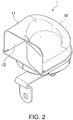
- Fig. 2 is an external view of the resonator 1 according to the first embodiment.
- the resonator 1 comprises a sound guide 10.
- the sound guide 10 is spirally shaped.
- the sound guide 10 comprises a wall 11 and a sound outlet 12.
- the wall 11 is an enclosure wall with an approximately U-shaped cross section and a predetermined thickness. On an internal side of the wall 11, a path is formed. The path is formed for the sound produced in the horn body part 2 to pass through. In the central part of the spiral shape in the sound guide 10, a sound inlet (not shown) for the sound produced in the horn body part 2 to get into is arranged.
- the sound outlet 12 is a bugle-shaped opening part arranged on an outlet side of the sound guide 10.
- the sound produced in the horn body part 2 resonates from the sound inlet of the resonator 1 through the sound guide 10 and is amplified to a predetermined sound pressure. Then, the amplified sound is produced outside from the sound outlet 12 of the resonator 1.
- the horn body part 2 comprises a case 20, a diaphragm 21, a movable iron core 22, a fixed iron core 23, a coil 24, a cover 25, an air vibration chamber (chamber) 26, an airflow path 27 and a control device 28.
- the diaphragm 21, the movable iron core 22, the fixed iron core 23, the coil 24, the cover 25, the air vibration chamber (chamber) 26, the airflow path 27 and the control device 28 are accommodated.
- the diaphragm 21 is arranged to infill the opening part of the case 20.
- the diaphragm 21 is, formed to an approximate disk shape by stamping a thin steel plate for example.
- the movable iron core 22 is fixed in the central part of the diaphragm 21, the movable iron core 22 is fixed.
- the diaphragm 21 is fixed to the resonator 1 by being fastened with a washer W.
- the movable iron core 22 is formed to a cylinder shape by magnetic material. One end of the movable iron core 22 is fixed to the diaphragm, and the other end is disposed facing the fixed iron core 23.
- the shaft center of the movable iron core 22 corresponds with the shaft center of the fixed iron core 23. That is, the movable iron core 22 and the fixed iron core 23 are disposed coaxially with each other.
- the fixed iron core 23 is disposed on the center of the coil 24. That is, the fixed iron core 23 and the coil 24 are formed as an electromagnet. Besides, the fixed iron core 23 is fixed to the case 20.
- the coil 24 is formed by conductive material, and is wound with a predetermined number of turns.
- the coil 24 is electrically connected with the control device 28.
- the cover 25 is fixed to the case 20.
- the periphery section of the cover 25 is fastened to both the periphery section of the case 20 and the periphery section of the diaphragm 21.
- An air vibration chamber 26 is formed between the cover 25 and the diaphragm 21.
- the airflow path 27 is formed between the cover 25 and the washer W.
- the airflow path 27 is configured to let the air from the air vibration chamber 26 pass through, accompanied by the vibration of the diaphragm 21.
- control device 28 By energizing the coil 24, the control device 28 turns the fixed iron core 23 disposed on the center of the coil 24 to an electromagnet and produces magnetic force.
- the control device 28 moves the movable iron core 22 back and forth to vibrate the diaphragm 21. Accordingly, a volume of the ring-shaped air vibration chamber 26, which is formed between the cover 25 and the diaphragm 21, increases or decreases. Therefore, air flowing is generated in the airflow path 27. In this way, the diaphragm 21 vibrates at a predetermined frequency f out , and the vibration becomes sound and is produced from the airflow path 27.
- the resonance frequency f c is a value determined by, for example, the shape or material of the diaphragm 21 or the resonator 1, and varies in accordance with the ambient temperature of the horn device A or the heat generation of the coil 24.
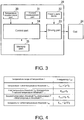
- the control device 28 comprises a temperature measurement part 30, a current measurement part 31, a power supply device 32, a driving part 33, a control part 34 and a memory part 35.
- the temperature measurement part 30 measures the ambient temperature T of the horn device A.
- the temperature measurement part 30 is arranged inside the control device 28. Then, the temperature measurement part 30 measures the temperature inside the control device 28 as the temperature T. The temperature measurement part 30 outputs the measured temperature T to the control part 34.
- the current measurement part 31 measures a current value Ic flowing through the coil 24.
- the current measurement part 31 outputs the measured current value Ic to the control part 34.
- the current measurement part 31 is a current transformer (CT).
- CT current transformer
- the current measurement part 31 is a current measurement circuit, which comprises a shunt resistor arranged on the path of the current flowing through the coil 24 and is configured to be capable of measuring the current value Ic from the voltages of two ends of the shunt resistor.
- the power supply device 32 supplies power to each part of the control device 28.
- the power supply device 32 is a battery.
- secondary batteries such as a nickel-hydrogen battery or a lithium-ion battery can be used as the power supply device 32.
- an electric double layer capacitor (condenser) can also be used.
- the driving part 33 Based on a PWM (Pulse Width Modulation) signal output from the control part 34, the driving part 33 converts the direct-current power from the power supply device 32 to an alternating-current power, and outputs the converted alternating-current power to the coil 24. In this way, the coil 24 is energized.
- PWM Pulse Width Modulation
- the control part 34 By outputting the PWM signal to the driving part 33, the control part 34 energizes the coil 24 and vibrates the diaphragm 21 at a predetermined frequency. In this case, the control part 34 changes the frequency which vibrates the diaphragm 21 according to the temperature T measured in the temperature measurement part 30.
- the frequency at which the diaphragm 21 vibrates (referred to as “vibration frequency” hereinafter) is the frequency f out of the PWM signal.
- the control part 34 moves the movable iron core 22 back and forth to vibrate the diaphragm 21.
- the frequency f out is set to correspond with the resonance frequency fc.
- the control part 34 can also set the frequency f out corresponding with the temperature T measured by the temperature measurement part 30 based on, for example, a table stored in the memory part 35 in advance. In the following part, the setting method of the frequency f out according to the first embodiment is described with reference to Fig. 4 .
- different frequencies f out with respect to each predetermined temperature range of the temperature T are stored in the form of a table.
- the frequency f out is set to a value (fo+fx) obtained by adding a predetermined frequency fx to a frequency fo.
- the frequency fo is the initial value of the frequency of PWM signals.
- the frequency f out is set to the frequency f 0 .
- the frequency f 0 is the resonance frequency fc in normal temperature range (higher than the first temperature threshold T th1 and lower than the second temperature threshold T th2 ).
- the frequency f out is set to a value (fo-fx) obtained by subtracting a predetermined fx from the frequency fo.
- the frequency f out is set to a value (f 0 -2fx) obtained by subtracting a predetermined 2 ⁇ fx from the frequency fo.
- the temperature range and the frequency f out shown in Fig. 4 are just examples, and the number of temperature ranges or the frequency f out can be properly set. However, the frequency f out is set to increase as the temperature T decreases.
- control part 34 changes a duty ratio D out of the energization to the coil 24 according to the current value Ic measured by the current measurement part 31.
- control part 34 sets the duty ratio corresponding to the current value Ic measured by the current measurement part 31 as the duty ratio D out of the PWM signal.
- the control part 34 can also set the duty ratio D out corresponding to the current value Ic measured by the current measurement part 31 based on, for example, a table stored in the memory part 35 in advance.
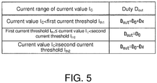
- the setting method of the duty ratio D out according to one embodiment of the present invention is described with reference to Fig. 5 .
- different duty ratios D out with respect ot each predetermined current range of the current value Ic are stored in the form of a table.
- the duty ratio D out is set to a value (Do+Dx) obtained by adding a predetermined duty ratio Dx to a duty ratio Do.
- the duty ratio Do is the initial value of the duty ratio of PWM signal.
- the duty ratio D out is set to the duty ratio Do.
- the duty ratio D out is set to a value (Do-Dx) obtained by subtracting the duty ratio Dx from the duty ratio Do.
- Do-Dx a value obtained by subtracting the duty ratio Dx from the duty ratio Do.
- the current range and the duty ratio D out shown in Fig. 5 are just examples, and the number of the current ranges or the duty ratio D out can be properly set.
- the duty ratio D out is set in the range between the upper limit and the lower limit. And the duty ratio D out is set to decrease as the current value Ic increases.
- the control part 34 sets the frequency f out to the frequency fo which is the initial value. Besides, the control part 34 sets the duty ratio D out to the duty ratio Do which is the initial value (step S101).
- the control part 34 when a warning signal is obtained from outside, the control part 34 generates PWM signals of the set frequency f out and duty ratio D out , and outputs the generated PWM signals to the driving part 33. In this way, the control part 34 energizes the coil 24 and vibrates the diaphragm 21 at the frequency fo, by which sound is produced from the sound outlet 12 of the resonator 1 to outside.
- the control part 34 obtains the temperature T from the temperature measurement part 30.
- the control part 34 determines whether the obtained temperature T is lower than the first temperature threshold T th1 (step S103). In the case when the obtained temperature T is determined to be lower than the first temperature threshold T th1 , the control part 34 sets the frequency f out to a value (fo+fx) obtained by adding the predetermined frequency fx to the frequency fo (step S104).
- the expression that the temperature T is lower than the first temperature threshold T th1 means that the temperature T is in a range of low temperature.
- the resonance frequency fc becomes higher and higher as the ambient temperature decreases.
- the control part 34 determines whether the temperature T is lower than the second temperature threshold T th2 (step S105).
- the control part 34 sets the frequency f out to the frequency fo (step S106). In this way, in the treatment of step S105, when the temperature T is determined to be within a range of normal temperature, the control part 34 sets the present frequency f out to the frequency fo in order to match the frequency f out with the resonance frequency fc.
- the control part 34 determines whether the temperature T is lower than the third temperature threshold T th3 (step S107).
- the control part 34 sets the frequency f out to the value (fo-fx) obtained by subtracting the predetermined fx from the frequency fo (step S108).
- the temperature T is higher than the second temperature threshold T th2 means that the temperature T is in the range of high temperature.
- the resonance frequency fc becomes lower and lower as the ambient temperature increases.
- the control part 34 obtains the current value Ic from the current measurement part 31 (step S110).
- the control part 34 determines whether the obtained current value Ic is higher than the first current threshold I th1 (step S111).
- the control part 34 determines whether the present duty ratio D out is the upper limit (step S112).
- the control part 34 sets a value obtained by adding a predetermined duty ratio Dx (for example, 10%) to the present duty ratio D out as a new duty ratio D out .
- the control part 34 sets the present duty ratio D out to the duty ratio Do (step S115).
- the control part 34 determines whether the current value Ic is lower than the second current threshold I th2 (step S114). When the obtained current value Ic is determined to be higher than the first current threshold I th1 and lower than the second current threshold I th2 , the control part 34 sets the present duty ratio D out to the duty ratio Do (step S115).
- the control part 34 determines whether the present duty ratio D out is the lower limit (step S116). When it is determined that the present duty ratio D out is not the lower limit, the control part 34 sets a value obtained by subtracting a predetermined duty ratio Dx (for example, 10%) from the present duty ratio D out as a new duty ratio D out (step S117). On the other hand, when the present duty ratio D out is determined to be the lower limit, the control part 34 sets the present duty ratio D out to the duty ratio Do (step S115).
- a predetermined duty ratio Dx for example, 10%
- the control part 34 usually controls the current value Ic flowing through the coil 24 to a scope ranging from the first current threshold I th1 to the second current threshold I th2 .
- the resistance value of the coil 24 changes, so that the current value Ic flowing through the coil 24 may fall outside the scope ranging from the first current threshold I th1 to the second current threshold I th2 .
- the current value flowing through the coil 24 may increase above the second current threshold I th2 . In this situation, because the current value flowing through the coil 24 increases, the magnetic force of the electromagnet increases.
- the movable iron core 22 and the fixed iron core 23 may collide with each other, resulting in an abnormal noise. Therefore, when the current value Ic flowing through the coil 24 increases above the second current threshold I th2 , the control part 34 of this embodiment prevents the increase of the magnetic force of the electromagnet by reducing the duty ratio D out . Accordingly, the control part 34 can prevent the abnormal noise generated due to the collision of the movable iron core 22 and the fixed iron core 23.
- the horn device A changes the frequency which vibrates the diaphragm 21 according to the temperature T measured by the temperature measurement part 30.
- the horn device A can correct the vibration frequency of the diaphragm 21 to the resonance frequency fc even when the resonance frequency fc changes because of the change of the ambient temperature. Therefore, the horn device A can ensure the predetermined sound pressure even when the resonance frequency fc of the diaphragm 21 changes because of the increasing or decreasing of the ambient temperature.
- the aforementioned horn device A changes the duty ratio D out according to the current value Ic flowing through the coil 24. Accordingly, the control part 34 prevented the increase of the current value Ic flowing through the coil 24 due to the decreasing of the ambient temperature. Therefore, the horn device A can prevent the abnormal noise which is generated because the movable iron core 22 and the fixed iron core 23 collide with each other due to the increasing of the current value Ic.
- the control part 34 may deviate the frequency f out from the resonance frequency fc by changing the corrected frequency f out . Accordingly, the vibration of the diaphragm 21 can be prevented and the abnormal noise can be prevented.
- the control part 34 may deviate the frequency f out from the resonance frequency fc by performing the treatment (step S201) in which a value obtained by subtracting 2 ⁇ fx from the present frequency f' out is set as the new frequency f out . That is, when the temperature T is lower than the predetermined temperature, the control part 34 reduces the vibration frequency.
- the present frequency is referred to as the value f' out.
- the setting method of the frequency f out in steps S104, 106, 108 and 109 is just an example, and the present invention is not limited to this situation. That is, when the temperature T falls into the range of low temperature, the control part 34 just has to set the frequency f out to a value lower than the frequency fo, and when the temperature T falls into the range of high temperature, the control part 34 just has to set the frequency f out to a value higher than the frequency fo.
- Fig. 8 is a drawing showing one example of a schematic structure of a horn device B according to a second embodiment. As shown in Fig. 8 , the horn device B comprises a resonator 1 and a horn body part 2B.
- the resonator 1 is mounted to the horn body part 2B.
- the resonator 1 resonates the sound produced by the horn body part 2B and produces sound outside.
- the horn body part 2B comprises a case 20, a diaphragm 21, a movable iron core 22, a fixed iron core 23, a coil 24, a cover 25, an air vibration chamber 26, an airflow path 27 and a control device 28B.
- the control device 28B comprises a temperature measurement part 30, a voltage measurement part 40, a power supply device 32, a driving part 33, a control part 34B and a memory part 35.
- the voltage measurement part 40 measures a voltage value Vb used to vibrate the diaphragm 21.
- the voltage measurement part 40 measures the voltage value Vb output from the power supply device 32.
- the voltage value Vb may be a voltage applied to the coil 24.
- the voltage measurement part 40 outputs the measured voltage Vb to the control part 34B.
- the control part 34B energizes the coil 24 and vibrates the diaphragm 21 at a predetermined frequency by outputting PWM signals to the driving part 33. In this situation, the control part 34 changes the frequency which vibrates the diaphragm 21 according to the temperature T measured by the temperature measurement part 30. Besides, the control part 34B changes the duty ratio D out of the energization to the coil 24 according to the voltage value Vb measured by the voltage measurement part 40.
- control part 34B sets the duty ratio of the PWM signals to the duty ratio D out corresponding to the voltage value Vb measured by the voltage measurement part 40.
- the control part 34B may also set the duty ratio D out corresponding to the voltage value Vb measured by the voltage measurement part 40 based on, for example, a table stored in the memory part 35 in advance.
- the setting method of the duty ratio D out according to one embodiment of the present invention is described with reference to Fig. 10 .
- different duty ratios D out with respect to each predetermined voltage range of the voltage value Vb are stored in the form of a table.
- the duty ratio D out is set to a value, for example, (D 0 +70%) obtained by adding a predetermined value such as 70% to the duty ratio Do.
- the duty ratio D out is set to a value, for example, (D 0 +65%) obtained by adding a predetermined value 65% to the duty ratio Do.
- the duty ratio D out is set to a value, for example, (D 0 +55%) obtained by adding a predetermined value 55% to the duty ratio Do.
- the duty ratio D out is set to a value, for example, (D 0 +45%) obtained by adding a predetermined value 45% to the duty ratio D 0 .
- the duty ratio D out is set to a value, for example, (Do+40%) obtained by adding a predetermined value 40% to the duty ratio Do. In this way, the duty ratio D out is set to decrease as the voltage value Vb increases.
- step S301 to step S309 are the same as the treatments from step S101 to step S109 of the first embodiment, the description is omitted.
- control part 34B obtains the voltage value Vb from the voltage measurement part 40 (step S310).
- the control part 34B determines whether the obtained voltage value Vb is higher than the first voltage threshold V th1 (step S311).
- the control part 34B sets a value obtained by adding 70% to the present duty ratio D out as a new duty ratio D out (step S312).
- the control part 34B determines whether the voltage value Vb is lower than the second voltage threshold V th2 (step S313).
- the control part 34B sets a value obtained by adding 65% to the present duty ratio D out as a new duty ratio D out (step S314).
- the control part 34B determines whether the obtained voltage value Vb is lower than the third voltage threshold V th3 (step S315).
- the control part 34B sets a value obtained by adding 55% to the present duty ratio D out as a new duty ratio D out (step S316).
- the control part 34B determines whether the obtained voltage value Vb is lower than the fourth voltage threshold Vth4 (step S317).
- the control part 34B sets a value obtained by adding 45% to the present duty ratio D out as a new duty ratio D out (step S318).
- the control part 34B sets a value obtained by adding 40% to the present duty ratio D out as a new duty ratio D out (step S319).
- control part 34B changes the duty ratio of the energization to the coil 24 according to the voltage value Vb measured by the voltage measurement part 40. Accordingly, the control part 34 can prevent the abnormal noise which is generated because the movable iron core 22 and the fixed iron core 23 collide with each other due to the increasing of the voltage value Vb.
- the control part 34B may deviate the frequency f out from the resonance frequency fc by changing the corrected frequency f out . Accordingly, the vibration of the diaphragm 21 can be prevented and the abnormal noise can be prevented.
- the control part 34B may deviate the frequency f out from the resonance frequency fc by performing the treatment (step S201) in which a value obtained by subtracting 2 ⁇ fx from the present frequency f' out is set as the new frequency f out . That is, when the temperature T is lower than the predetermined temperature, the control part 34B reduces the vibration frequency.
- the present frequency is referred to as the value f' out .
- the control part 34 and 34B of the aforementioned embodiment may also be realized by a computer.
- a program used to realize the function may be recorded in a computer-readable recording medium, and the function may be realized by making a computer system read in the program recorded in the recording medium and implementing the program.
- the "computer system” mentioned here includes a hardware such as OS or peripheral device.
- the "computer-readable recording medium” is a memory device such as a movable medium like a flexible disk, a magnetic optical disk, a ROM and a CD-ROM, and a built-in hard disk in the computer system.
- computer-readable recording medium means a recording medium which dynamically keeps programs for a short time like a communication wire that transmits programs via a network such as the Internet or via a communication line such as a telephone line, including a recording medium which keeps programs for a specific time like a volatile memory within the computer system which becomes a server or client in this situation.
- the programs may be programs which are used to realized a part of the functions, may be programs realized by a further combination with programs which already record the functions in the computer system, or may be programs which are realized by using programmable logic arrays such as a FPGA (Field Programmable Gate Array).
Landscapes
- Physics & Mathematics (AREA)
- Engineering & Computer Science (AREA)
- Acoustics & Sound (AREA)
- Signal Processing (AREA)
- Electromagnetism (AREA)
- Multimedia (AREA)
- Apparatuses For Generation Of Mechanical Vibrations (AREA)
Abstract
Description
- The present invention relates to a horn device.
- In
patent literature 1, a horn device is disclosed which vibrates a diaphragm at a predetermined vibration frequency by magnetic force of an electromagnet, and resonate by a resonator the sound produced by the vibration to produce sound. - [Patent Literature 1] Japanese Patent Application Laid-Open No.
2017-9624 - By the way, in the horn device, due to the change of ambient temperature or the change of voltage value which is used to vibrate the diaphragm, the resonance frequency of the diaphragm which is the frequency with the greatest amplitude changes. Accordingly, the vibration frequency of the diaphragm deviates from the resonance frequency, and sound pressure decreases.
- The present invention is accomplished in view of such situation, and aims at providing a horn device which is capable of preventing the decrease of the sound pressure.
- One of the embodiments of the present invention is a horn device, which is configured to resonate, by a resonator, sound produced by vibrating a diaphragm, comprising: a control part configured to vibrate the diaphragm; and a temperature measurement part; wherein the control part changes a vibration frequency which vibrates the diaphragm according to a temperature measured by the temperature measurement part.
- One of the embodiments of the present invention is the aforementioned horn device, comprising: a coil; a fixed iron core, which is disposed on a center of the coil, and is fixed to a case; and a movable iron core, which is disposed facing the fixed iron core, and is fixed to the diaphragm; wherein the control part controls energization of the coil according to the vibration frequency corresponding to the temperature measured in the temperature measurement part and vibrates the diaphragm.
- One of the embodiments of the present invention is the aforementioned horn device, comprising a current measurement part which is configured to measure a current value flowing through the coil, wherein the control part changes a duty ratio of energization to the coil according to the current value measured by the current measurement part.
- One of the embodiments of the present invention is the aforementioned horn device, comprising a voltage measurement part which is configured to measure a voltage value used to vibrate the diaphragm, wherein the control part changes a duty ratio of energization to the coil according to the voltage value measured by the voltage measurement part.
- One of the embodiments of the present invention is the aforementioned horn device, wherein the control part reduces the vibration frequency when the temperature measured by the temperature measurement part is lower than a predetermined temperature.
- As described above, according to the present invention, decrease of the sound pressure can be prevented.
-
-
Fig. 1 is a drawing showing one example of a schematic structure of a horn device A according to a first embodiment. -
Fig. 2 is an external view of aresonator 1 according to the first embodiment. -
Fig. 3 is a drawing showing one example of a schematic structure of acontrol device 28 according to the first embodiment. -
Fig. 4 is a drawing illustrating a setting method of a frequency fout according to the first embodiment. -
Fig. 5 is a drawing illustrating a setting method of a duty ratio Dout according to the first embodiment. -
Fig. 6 is a flow chart of an operation of energization control of acoil 24 according to the first embodiment. -
Fig. 7 is a flow chart of a variation of the operation of energization control of thecoil 24 according to the first embodiment. -
Fig. 8 is a drawing showing one example of a schematic structure of a horn device B according to a second embodiment. -
Fig. 9 is a drawing showing one example of a schematic structure of acontrol device 28B according to the second embodiment. -
Fig. 10 is a drawing illustrating a setting method of a duty ratio Dout according to the second embodiment. -
Fig. 11 is a flow chart of an operation of energization control of acoil 24 according to the second embodiment. -
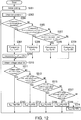
Fig. 12 is a flow chart of a variation of the operation of energization control of thecoil 24 according to the second embodiment. - In the following part, the present invention is described through embodiments of the invention, but the following embodiments do not limit the invention. Besides, not all the combinations of characteristics described in the embodiments are necessary to the solving method of the invention. In addition, in the drawings, the same or similar parts are marked with the same symbols and repeated description is omitted sometimes. Moreover, shapes, sizes and the like of the elements in the drawings may be exaggeratedly shown for a clearer description.
- In the whole specification, as long as no opposing description exists, the expression that a certain part "include(s)", "has/have" or "comprise(s)" a certain structural element means that other structural elements can be further included instead of being excluded.
- In the following part, a horn device according to one embodiment of the present invention is described with reference to drawings. The horn device according to one embodiment of the present invention is, for example, a horn device which is mounted on a front side of a vehicle such as an automobile and produces a warning sound.
-
Fig. 1 is a drawing showing one example of a schematic structure of a horn device A according to a first embodiment. As shown inFig. 1 , the horn device A comprises aresonator 1 and ahorn body part 2.
Theresonator 1 is mounted on thehorn body part 2. Theresonator 1 resonates the sound produced by thehorn body part 2 and produces sound outside. -
Fig. 2 is an external view of theresonator 1 according to the first embodiment. As shown inFig. 2 , theresonator 1 comprises asound guide 10.
Thesound guide 10 is spirally shaped. Thesound guide 10 comprises awall 11 and asound outlet 12. - The
wall 11 is an enclosure wall with an approximately U-shaped cross section and a predetermined thickness. On an internal side of thewall 11, a path is formed. The path is formed for the sound produced in thehorn body part 2 to pass through.
In the central part of the spiral shape in thesound guide 10, a sound inlet (not shown) for the sound produced in thehorn body part 2 to get into is arranged.
Thesound outlet 12 is a bugle-shaped opening part arranged on an outlet side of thesound guide 10. - According to the aforementioned structure, the sound produced in the
horn body part 2 resonates from the sound inlet of theresonator 1 through thesound guide 10 and is amplified to a predetermined sound pressure. Then, the amplified sound is produced outside from thesound outlet 12 of theresonator 1. - Back to
Fig. 1 , the structure of thehorn body part 2 according to the first embodiment is described.
Thehorn body part 2 comprises acase 20, adiaphragm 21, amovable iron core 22, afixed iron core 23, acoil 24, acover 25, an air vibration chamber (chamber) 26, anairflow path 27 and acontrol device 28. - In the
case 20, thediaphragm 21, themovable iron core 22, thefixed iron core 23, thecoil 24, thecover 25, the air vibration chamber (chamber) 26, theairflow path 27 and thecontrol device 28 are accommodated. - The
diaphragm 21 is arranged to infill the opening part of thecase 20. Thediaphragm 21 is, formed to an approximate disk shape by stamping a thin steel plate for example. In the central part of thediaphragm 21, themovable iron core 22 is fixed. For example, thediaphragm 21 is fixed to theresonator 1 by being fastened with a washer W. - The
movable iron core 22 is formed to a cylinder shape by magnetic material. One end of themovable iron core 22 is fixed to the diaphragm, and the other end is disposed facing the fixediron core 23. Here, the shaft center of themovable iron core 22 corresponds with the shaft center of the fixediron core 23. That is, themovable iron core 22 and the fixediron core 23 are disposed coaxially with each other. - The fixed
iron core 23 is disposed on the center of thecoil 24. That is, the fixediron core 23 and thecoil 24 are formed as an electromagnet. Besides, the fixediron core 23 is fixed to thecase 20. - The
coil 24 is formed by conductive material, and is wound with a predetermined number of turns. Thecoil 24 is electrically connected with thecontrol device 28.
Thecover 25 is fixed to the case 20.The periphery section of thecover 25 is fastened to both the periphery section of thecase 20 and the periphery section of thediaphragm 21. - An
air vibration chamber 26 is formed between thecover 25 and thediaphragm 21.
Theairflow path 27 is formed between thecover 25 and the washer W. Theairflow path 27 is configured to let the air from theair vibration chamber 26 pass through, accompanied by the vibration of thediaphragm 21. - By energizing the
coil 24, thecontrol device 28 turns the fixediron core 23 disposed on the center of thecoil 24 to an electromagnet and produces magnetic force. - In the following part, a sound producing method according to the first embodiment is described.
By the magnetic force generated by the energization control performed to thecoil 24 at a predetermined frequency fout, thecontrol device 28 moves themovable iron core 22 back and forth to vibrate thediaphragm 21. Accordingly, a volume of the ring-shapedair vibration chamber 26, which is formed between thecover 25 and thediaphragm 21, increases or decreases. Therefore, air flowing is generated in theairflow path 27. In this way, thediaphragm 21 vibrates at a predetermined frequency fout, and the vibration becomes sound and is produced from theairflow path 27. In addition, when the predetermined frequency fout is approximately the same as the resonance frequency fc, the sound pressure is the largest. Moreover, the resonance frequency fc is a value determined by, for example, the shape or material of thediaphragm 21 or theresonator 1, and varies in accordance with the ambient temperature of the horn device A or the heat generation of thecoil 24. - In the following part, the structure of the
control device 28 according to the first embodiment is described with reference toFig. 3 .
As shown inFig. 3 , thecontrol device 28 comprises atemperature measurement part 30, acurrent measurement part 31, apower supply device 32, a drivingpart 33, acontrol part 34 and amemory part 35.
Thetemperature measurement part 30 measures the ambient temperature T of the horn device A. For example, thetemperature measurement part 30 is arranged inside thecontrol device 28. Then, thetemperature measurement part 30 measures the temperature inside thecontrol device 28 as the temperature T. Thetemperature measurement part 30 outputs the measured temperature T to thecontrol part 34. - The
current measurement part 31 measures a current value Ic flowing through thecoil 24. Thecurrent measurement part 31 outputs the measured current value Ic to thecontrol part 34. For example, thecurrent measurement part 31 is a current transformer (CT). Besides, thecurrent measurement part 31 is a current measurement circuit, which comprises a shunt resistor arranged on the path of the current flowing through thecoil 24 and is configured to be capable of measuring the current value Ic from the voltages of two ends of the shunt resistor. - The
power supply device 32 supplies power to each part of thecontrol device 28. For example, thepower supply device 32 is a battery. For example, secondary batteries such as a nickel-hydrogen battery or a lithium-ion battery can be used as thepower supply device 32. Besides, instead of secondary batteries, an electric double layer capacitor (condenser) can also be used. - Based on a PWM (Pulse Width Modulation) signal output from the
control part 34, the drivingpart 33 converts the direct-current power from thepower supply device 32 to an alternating-current power, and outputs the converted alternating-current power to thecoil 24. In this way, thecoil 24 is energized. - By outputting the PWM signal to the driving
part 33, thecontrol part 34 energizes thecoil 24 and vibrates thediaphragm 21 at a predetermined frequency. In this case, thecontrol part 34 changes the frequency which vibrates thediaphragm 21 according to the temperature T measured in thetemperature measurement part 30. Here, the frequency at which thediaphragm 21 vibrates (referred to as "vibration frequency" hereinafter) is the frequency fout of the PWM signal. - For example, by controlling the energization of the
coil 24 at the frequency fout corresponding to the temperature T measured by thetemperature measurement part 30, thecontrol part 34 moves themovable iron core 22 back and forth to vibrate thediaphragm 21. In addition, the frequency fout is set to correspond with the resonance frequency fc.
Thecontrol part 34 can also set the frequency fout corresponding with the temperature T measured by thetemperature measurement part 30 based on, for example, a table stored in thememory part 35 in advance. In the following part, the setting method of the frequency fout according to the first embodiment is described with reference toFig. 4 . - As shown in
Fig. 4 , in thememory part 35, different frequencies fout with respect to each predetermined temperature range of the temperature T are stored in the form of a table. For example, when the temperature T is lower than a first temperature threshold Tth1, the frequency fout is set to a value (fo+fx) obtained by adding a predetermined frequency fx to a frequency fo. Here, the frequency fo is the initial value of the frequency of PWM signals. - When the temperature T is higher than the first temperature threshold Tth1 and lower than a second temperature threshold Tth2 (>Tth1), the frequency fout is set to the frequency f0. In addition, the frequency f0 is the resonance frequency fc in normal temperature range (higher than the first temperature threshold Tth1 and lower than the second temperature threshold Tth2).
When the temperature T is higher than the second temperature threshold Tth2 and lower than a third temperature threshold Tth3 (>Tth2), the frequency fout is set to a value (fo-fx) obtained by subtracting a predetermined fx from the frequency fo. When the temperature T is higher than the third temperature threshold Tth3, the frequency fout is set to a value (f0-2fx) obtained by subtracting a predetermined 2×fx from the frequency fo. Moreover, the temperature range and the frequency fout shown inFig. 4 are just examples, and the number of temperature ranges or the frequency fout can be properly set. However, the frequency fout is set to increase as the temperature T decreases. - Besides, the
control part 34 changes a duty ratio Dout of the energization to thecoil 24 according to the current value Ic measured by thecurrent measurement part 31. For example, thecontrol part 34 sets the duty ratio corresponding to the current value Ic measured by thecurrent measurement part 31 as the duty ratio Dout of the PWM signal. Thecontrol part 34 can also set the duty ratio Dout corresponding to the current value Ic measured by thecurrent measurement part 31 based on, for example, a table stored in thememory part 35 in advance. In the following part, the setting method of the duty ratio Dout according to one embodiment of the present invention is described with reference toFig. 5 . - As shown in
Fig. 5 , in thememory part 35, different duty ratios Dout with respect ot each predetermined current range of the current value Ic are stored in the form of a table. For example, when the current value Ic is lower than a first current threshold Ith1, the duty ratio Dout is set to a value (Do+Dx) obtained by adding a predetermined duty ratio Dx to a duty ratio Do. Here, the duty ratio Do is the initial value of the duty ratio of PWM signal. When the current value Ic is higher than the first current threshold Ith1 and lower than a second current threshold Ith2 (>Ith1), the duty ratio Dout is set to the duty ratio Do. - When the current value Ic is higher than the second current threshold Ith2, the duty ratio Dout is set to a value (Do-Dx) obtained by subtracting the duty ratio Dx from the duty ratio Do. In addition, the current range and the duty ratio Dout shown in
Fig. 5 are just examples, and the number of the current ranges or the duty ratio Dout can be properly set. However, the duty ratio Dout is set in the range between the upper limit and the lower limit. And the duty ratio Dout is set to decrease as the current value Ic increases. - In the following part, the operation of the energization control of the
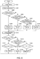
coil 24 according to this embodiment is described with reference toFig. 6 .
First, thecontrol part 34 sets the frequency fout to the frequency fo which is the initial value. Besides, thecontrol part 34 sets the duty ratio Dout to the duty ratio Do which is the initial value (step S101). Here, when a warning signal is obtained from outside, thecontrol part 34 generates PWM signals of the set frequency fout and duty ratio Dout, and outputs the generated PWM signals to the drivingpart 33. In this way, thecontrol part 34 energizes thecoil 24 and vibrates thediaphragm 21 at the frequency fo, by which sound is produced from thesound outlet 12 of theresonator 1 to outside. - Next, the
control part 34 obtains the temperature T from thetemperature measurement part 30. Thecontrol part 34 determines whether the obtained temperature T is lower than the first temperature threshold Tth1 (step S103). In the case when the obtained temperature T is determined to be lower than the first temperature threshold Tth1, thecontrol part 34 sets the frequency fout to a value (fo+fx) obtained by adding the predetermined frequency fx to the frequency fo (step S104). Here, the expression that the temperature T is lower than the first temperature threshold Tth1 means that the temperature T is in a range of low temperature. Here, the resonance frequency fc becomes higher and higher as the ambient temperature decreases. Therefore, in the treatment of step S104, when the ambient temperature is a low temperature, thecontrol part 34 adds the frequency fx to the frequency fo which is the present frequency fout in order to match the frequency fout with the resonance frequency fc. That is, thecontrol part 34 corrects the frequency fout to the resonance frequency fc which becomes a higher value as the temperature decreases. Accordingly, the frequency fout is set to the resonance frequency fc (=fo+fx). - When the obtained temperature T is higher than the first temperature threshold Tth1, the
control part 34 determines whether the temperature T is lower than the second temperature threshold Tth2 (step S105). When the obtained temperature T is determined to be higher than the first temperature threshold Tth1 and lower than the second temperature threshold Tth2, thecontrol part 34 sets the frequency fout to the frequency fo (step S106). In this way, in the treatment of step S105, when the temperature T is determined to be within a range of normal temperature, thecontrol part 34 sets the present frequency fout to the frequency fo in order to match the frequency fout with the resonance frequency fc. - On the other hand, when the obtained temperature T is determined to be higher than the second temperature threshold Tth2, the
control part 34 determines whether the temperature T is lower than the third temperature threshold Tth3 (step S107). When the obtained temperature T is determined to be higher than the second temperature threshold Tth2 and lower than the third temperature threshold Tth3, thecontrol part 34 sets the frequency fout to the value (fo-fx) obtained by subtracting the predetermined fx from the frequency fo (step S108). Here, the temperature T is higher than the second temperature threshold Tth2 means that the temperature T is in the range of high temperature. Here, the resonance frequency fc becomes lower and lower as the ambient temperature increases. Therefore, in the treatment of step S108, when the ambient temperature is a high temperature, thecontrol part 34 subtracts the frequency fx from the frequency fo which is the present frequency fout in order to match the frequency fout with the resonance frequency fc. That is, thecontrol part 34 corrects the frequency fout to the resonance frequency fc which becomes a low value as the temperature becomes high. Accordingly, the frequency fout is set to the resonance frequency fc (=fo-fx). - When the obtained temperature T is determined to be higher than the third temperature threshold Tth3, the
control part 34 sets the frequency fout to the value (f0-2fx) obtained by subtracting 2×fx from the frequency fo (step S109). That is, when the temperature T is higher than the third temperature threshold Tth3, the resonance frequency fc becomes a value even lower than the value (fo+fx) set in the treatment of step S108. Therefore, in the treatment of step S109, thecontrol part 34 subtracts a value two times of the frequency fx from the frequency fo which is the present frequency fout in order to match the frequency fout with the resonance frequency fc. Accordingly, the frequency fout is set to the resonance frequency fc (=f0-2fx). - Next, the
control part 34 obtains the current value Ic from the current measurement part 31 (step S110). Thecontrol part 34 determines whether the obtained current value Ic is higher than the first current threshold Ith1 (step S111). When the obtained current value Ic is determined to be lower than the first current threshold Ith1, thecontrol part 34 determines whether the present duty ratio Dout is the upper limit (step S112). When it is determined that the present duty ratio Dout is not the upper limit, thecontrol part 34 sets a value obtained by adding a predetermined duty ratio Dx (for example, 10%) to the present duty ratio Dout as a new duty ratio Dout. Accordingly, when the current value Ic flowing through thecoil 24 is lower than the first current threshold Ith1, the duty ratio Dout is raised (step S113). However, when the present duty ratio Dout is determined to be the upper limit, thecontrol part 34 sets the present duty ratio Dout to the duty ratio Do (step S115). - When the obtained current value Ic is determined to be higher than the first current threshold Ith1, the
control part 34 determines whether the current value Ic is lower than the second current threshold Ith2 (step S114). When the obtained current value Ic is determined to be higher than the first current threshold Ith1 and lower than the second current threshold Ith2, thecontrol part 34 sets the present duty ratio Dout to the duty ratio Do (step S115). - When the obtained current value Ic is determined to be higher than the second current threshold Ith2, the
control part 34 determines whether the present duty ratio Dout is the lower limit (step S116). When it is determined that the present duty ratio Dout is not the lower limit, thecontrol part 34 sets a value obtained by subtracting a predetermined duty ratio Dx (for example, 10%) from the present duty ratio Dout as a new duty ratio Dout (step S117). On the other hand, when the present duty ratio Dout is determined to be the lower limit, thecontrol part 34 sets the present duty ratio Dout to the duty ratio Do (step S115). - Here, the
control part 34 usually controls the current value Ic flowing through thecoil 24 to a scope ranging from the first current threshold Ith1 to the second current threshold Ith2. however, due to the change of the ambient temperature, the resistance value of thecoil 24 changes, so that the current value Ic flowing through thecoil 24 may fall outside the scope ranging from the first current threshold Ith1 to the second current threshold Ith2. For example, when the ambient temperature becomes a low temperature and the resistance value of thecoil 24 decrease, the current value flowing through thecoil 24 may increase above the second current threshold Ith2. In this situation, because the current value flowing through thecoil 24 increases, the magnetic force of the electromagnet increases. Accordingly, themovable iron core 22 and the fixediron core 23 may collide with each other, resulting in an abnormal noise. Therefore, when the current value Ic flowing through thecoil 24 increases above the second current threshold Ith2, thecontrol part 34 of this embodiment prevents the increase of the magnetic force of the electromagnet by reducing the duty ratio Dout. Accordingly, thecontrol part 34 can prevent the abnormal noise generated due to the collision of themovable iron core 22 and the fixediron core 23. - As mentioned above, the horn device A according to the first embodiment changes the frequency which vibrates the
diaphragm 21 according to the temperature T measured by thetemperature measurement part 30. In this way, the horn device A can correct the vibration frequency of thediaphragm 21 to the resonance frequency fc even when the resonance frequency fc changes because of the change of the ambient temperature. Therefore, the horn device A can ensure the predetermined sound pressure even when the resonance frequency fc of thediaphragm 21 changes because of the increasing or decreasing of the ambient temperature. - Besides, the aforementioned horn device A changes the duty ratio Dout according to the current value Ic flowing through the
coil 24. Accordingly, thecontrol part 34 prevented the increase of the current value Ic flowing through thecoil 24 due to the decreasing of the ambient temperature. Therefore, the horn device A can prevent the abnormal noise which is generated because themovable iron core 22 and the fixediron core 23 collide with each other due to the increasing of the current value Ic. - In addition, when the ambient temperature is low, the
control part 34 may deviate the frequency fout from the resonance frequency fc by changing the corrected frequency fout. Accordingly, the vibration of thediaphragm 21 can be prevented and the abnormal noise can be prevented. For example, as shown inFig. 7 , after the treatment of step S104, thecontrol part 34 may deviate the frequency fout from the resonance frequency fc by performing the treatment (step S201) in which a value obtained by subtracting 2×fx from the present frequency f'out is set as the new frequency fout. That is, when the temperature T is lower than the predetermined temperature, thecontrol part 34 reduces the vibration frequency. Moreover, in order to avoid the complication of the description, in steps S104 and S201 shown inFig. 7 , the present frequency is referred to as the value f'out. - Besides, in this embodiment, the setting method of the frequency fout in steps S104, 106, 108 and 109 is just an example, and the present invention is not limited to this situation. That is, when the temperature T falls into the range of low temperature, the
control part 34 just has to set the frequency fout to a value lower than the frequency fo, and when the temperature T falls into the range of high temperature, thecontrol part 34 just has to set the frequency fout to a value higher than the frequency fo. -
Fig. 8 is a drawing showing one example of a schematic structure of a horn device B according to a second embodiment. As shown inFig. 8 , the horn device B comprises aresonator 1 and ahorn body part 2B. - The
resonator 1 is mounted to thehorn body part 2B. Theresonator 1 resonates the sound produced by thehorn body part 2B and produces sound outside. - The
horn body part 2B comprises acase 20, adiaphragm 21, amovable iron core 22, a fixediron core 23, acoil 24, acover 25, anair vibration chamber 26, anairflow path 27 and acontrol device 28B. - As shown in
Fig. 9 , thecontrol device 28B comprises atemperature measurement part 30, avoltage measurement part 40, apower supply device 32, a drivingpart 33, acontrol part 34B and amemory part 35. - The
voltage measurement part 40 measures a voltage value Vb used to vibrate thediaphragm 21. For example, thevoltage measurement part 40 measures the voltage value Vb output from thepower supply device 32. Here, the voltage value Vb may be a voltage applied to thecoil 24. Thevoltage measurement part 40 outputs the measured voltage Vb to thecontrol part 34B. - The
control part 34B energizes thecoil 24 and vibrates thediaphragm 21 at a predetermined frequency by outputting PWM signals to the drivingpart 33. In this situation, thecontrol part 34 changes the frequency which vibrates thediaphragm 21 according to the temperature T measured by thetemperature measurement part 30. Besides, thecontrol part 34B changes the duty ratio Dout of the energization to thecoil 24 according to the voltage value Vb measured by thevoltage measurement part 40. - For example, the
control part 34B sets the duty ratio of the PWM signals to the duty ratio Dout corresponding to the voltage value Vb measured by thevoltage measurement part 40. Thecontrol part 34B may also set the duty ratio Dout corresponding to the voltage value Vb measured by thevoltage measurement part 40 based on, for example, a table stored in thememory part 35 in advance. In the following part, the setting method of the duty ratio Dout according to one embodiment of the present invention is described with reference toFig. 10 . - As shown in
Fig. 10 , in thememory part 35, different duty ratios Dout with respect to each predetermined voltage range of the voltage value Vb are stored in the form of a table. For example, when the voltage value Vb is lower than a first voltage threshold Vth1, the duty ratio Dout is set to a value, for example, (D0+70%) obtained by adding a predetermined value such as 70% to the duty ratio Do.
Besides, when the voltage value Vb is higher than the first voltage threshold Vth1 and lower than a second voltage threshold Vth2(>Vth1), the duty ratio Dout is set to a value, for example, (D0+65%) obtained by adding apredetermined value 65% to the duty ratio Do. Besides, when the voltage value Vb is higher than the second voltage threshold Vth2 and lower than a third voltage threshold Vth3(>Vth2), the duty ratio Dout is set to a value, for example, (D0+55%) obtained by adding apredetermined value 55% to the duty ratio Do. - Besides, when the voltage value Vb is higher than the third voltage threshold Vth3 and lower than the fourth voltage threshold Vth4(>Vth3), the duty ratio Dout is set to a value, for example, (D0+45%) obtained by adding a
predetermined value 45% to the duty ratio D0.
Besides, when the voltage value Vb is higher than the fourth voltage threshold Vth4, the duty ratio Dout is set to a value, for example, (Do+40%) obtained by adding apredetermined value 40% to the duty ratio Do.
In this way, the duty ratio Dout is set to decrease as the voltage value Vb increases. - In the following part, the operation of the energization control of the
coil 24 according to the second embodiment is described with reference toFig. 11 . In addition, because the treatments from step S301 to step S309 are the same as the treatments from step S101 to step S109 of the first embodiment, the description is omitted. - Next, the
control part 34B obtains the voltage value Vb from the voltage measurement part 40 (step S310). Thecontrol part 34B determines whether the obtained voltage value Vb is higher than the first voltage threshold Vth1 (step S311). When the obtained voltage value Vb is determined to be lower than the first voltage threshold Vth1, thecontrol part 34B sets a value obtained by adding 70% to the present duty ratio Dout as a new duty ratio Dout (step S312). - One the other hand, when the obtained voltage value Vb is determined to be higher than the first voltage threshold Vth1, the
control part 34B determines whether the voltage value Vb is lower than the second voltage threshold Vth2 (step S313). When the obtained voltage value Vb is determined to be higher than the first voltage threshold Vth1 and lower than the second voltage threshold Vth2, thecontrol part 34B sets a value obtained by adding 65% to the present duty ratio Dout as a new duty ratio Dout (step S314). - When the obtained voltage value Vb is determined to be higher than the second voltage threshold Vth2, the
control part 34B determines whether the obtained voltage value Vb is lower than the third voltage threshold Vth3 (step S315). When the obtained voltage value Vb is determined to be higher than the second voltage threshold Vth2 and lower than the third voltage threshold Vth3, thecontrol part 34B sets a value obtained by adding 55% to the present duty ratio Dout as a new duty ratio Dout (step S316). - When the obtained voltage value Vb is determined to be higher than the third voltage threshold Vth3, the
control part 34B determines whether the obtained voltage value Vb is lower than the fourth voltage threshold Vth4 (step S317). When the obtained voltage value Vb is determined to be higher than the third voltage threshold Vth3 and lower than the fourth voltage threshold Vth4, thecontrol part 34B sets a value obtained by adding 45% to the present duty ratio Dout as a new duty ratio Dout (step S318). - When the obtained voltage value Vb is determined to be higher than the fourth voltage threshold Vth4, the
control part 34B sets a value obtained by adding 40% to the present duty ratio Dout as a new duty ratio Dout (step S319). - In this way, the
control part 34B changes the duty ratio of the energization to thecoil 24 according to the voltage value Vb measured by thevoltage measurement part 40. Accordingly, thecontrol part 34 can prevent the abnormal noise which is generated because themovable iron core 22 and the fixediron core 23 collide with each other due to the increasing of the voltage value Vb. - In addition, when the ambient temperature is low, the
control part 34B may deviate the frequency fout from the resonance frequency fc by changing the corrected frequency fout. Accordingly, the vibration of thediaphragm 21 can be prevented and the abnormal noise can be prevented. For example, as shown inFig. 12 , after the treatment of step S304, thecontrol part 34B may deviate the frequency fout from the resonance frequency fc by performing the treatment (step S201) in which a value obtained by subtracting 2×fx from the present frequency f'out is set as the new frequency fout. That is, when the temperature T is lower than the predetermined temperature, thecontrol part 34B reduces the vibration frequency. Moreover, in order to avoid the complication of the description, in steps S304 and S201 shown inFig. 7 , the present frequency is referred to as the value f'out. - The
control part - In the aforementioned part, the embodiment of the present invention is described in detail with reference to the drawings, but the specific structure is not limited to the embodiment, and the designs in a scope not departing from the spirit of the present invention are also included.
- The fact should be noticed that the devices, systems and programs shown in the specification and the drawings, as well as the implementation sequence of each treatment of the operations, procedures, steps and stages in the method can be performed in any sequence as long as there is no particular description such as "before ...", "in advance of ..." and so on, and the result of the former treatment is not used in the latter treatment. As for the operation flow in the specification and the drawings, even if the expressions of "first", "next" and so on are used in the description for convenience, it is not necessary to follow this sequence.
-
- A, B
- Horn device
- 1
- Resonator
- 2, 2B
- Horn body part
- 20
- Case
- 21
- Diaphragm
- 22
- Movable iron core
- 23
- Fixed iron core
- 24
- Coil
- 25
- Cover
- 26
- Air vibration chamber (chamber)
- 27
- Airflow path
- 28, 28B
- Control device
- 30
- Temperature measurement part
- 31
- Current measurement part
- 32
- Power supply device
- 33
- Driving part
- 34, 34B
- Control part
- 35
- Memory part
- 40
- Voltage measurement part
Claims (5)
- A horn device (A, B), which is configured to resonate, by a resonator (1), sound produced by vibrating a diaphragm (21), comprising:a control part (34, 34B) configured to vibrate the diaphragm (21); anda temperature measurement part (30); whereinthe control part (34, 34B) changes a vibration frequency which vibrates the diaphragm (21) according to a temperature measured by the temperature measurement part (30).
- The horn device (A, B) according to claim 1, comprising:a coil (24);a fixed iron core (23), which is disposed on a center of the coil (24), and is fixed to a case (20); anda movable iron core (22), which is disposed facing the fixed iron core (23), and is fixed to the diaphragm (21); whereinthe control part (34, 34B) controls energization of the coil (24) according to the vibration frequency corresponding to the temperature measured in the temperature measurement part (30) and vibrates the diaphragm (21).
- The horn device (A) according to claim 2, comprising a current measurement part (31) which is configured to measure a current value flowing through the coil (24), wherein
the control part (34) changes a duty ratio of energization to the coil (24) according to the current value measured by the current measurement part (31). - The horn device (B) according to claim 2, comprising a voltage measurement part (40) which is configured to measure a voltage value used to vibrate the diaphragm (21), wherein
the control part (34B) changes a duty ratio of energization to the coil (24) according to the voltage value measured by the voltage measurement part (40). - The horn device (A, B) according to any one of claims 1 to 4, wherein the control part (34, 34B) reduces the vibration frequency when the temperature measured by the temperature measurement part (30) is lower than a predetermined temperature.
Applications Claiming Priority (1)
| Application Number | Priority Date | Filing Date | Title |
|---|---|---|---|
| JP2017068407A JP6825962B2 (en) | 2017-03-30 | 2017-03-30 | Horn device |
Publications (2)
| Publication Number | Publication Date |
|---|---|
| EP3382690A1 true EP3382690A1 (en) | 2018-10-03 |
| EP3382690B1 EP3382690B1 (en) | 2021-04-21 |
Family
ID=61801838
Family Applications (1)
| Application Number | Title | Priority Date | Filing Date |
|---|---|---|---|
| EP18162949.4A Active EP3382690B1 (en) | 2017-03-30 | 2018-03-20 | Horn device |
Country Status (3)
| Country | Link |
|---|---|
| EP (1) | EP3382690B1 (en) |
| JP (1) | JP6825962B2 (en) |
| CN (1) | CN108696803A (en) |
Citations (4)
| Publication number | Priority date | Publication date | Assignee | Title |
|---|---|---|---|---|
| GB2041616A (en) * | 1979-01-29 | 1980-09-10 | Ibuki Kogyo Co Ltd | Electric horns |
| US5293149A (en) * | 1991-04-12 | 1994-03-08 | Sparton Corporation | Vehicle horn with electronic solid state energizing circuit |
| US20080309466A1 (en) * | 2005-12-30 | 2008-12-18 | Hongwei Zhao | Adaptive intelligent electronic horn |
| JP2017009624A (en) | 2015-06-16 | 2017-01-12 | 株式会社ミツバ | Horn device |
Family Cites Families (6)
| Publication number | Priority date | Publication date | Assignee | Title |
|---|---|---|---|---|
| CN1040590C (en) * | 1992-08-14 | 1998-11-04 | 凌阳科技股份有限公司 | Vocoder |
| CN103500574B (en) * | 2012-08-16 | 2017-06-27 | 万喻 | A kind of intelligent electronic horn and its implementation |
| JP2014186972A (en) * | 2013-03-25 | 2014-10-02 | Yamaha Corp | Control signal generating apparatus and acoustic signal processing apparatus |
| JP6331418B2 (en) * | 2013-06-28 | 2018-05-30 | 株式会社アドヴィックス | Braking device for vehicle |
| JP6314496B2 (en) * | 2014-01-21 | 2018-04-25 | 浜名湖電装株式会社 | Alarm sound generator |
| CN205378300U (en) * | 2016-02-25 | 2016-07-06 | 西安科技大学 | Vehicle headlamp control device |
-
2017
- 2017-03-30 JP JP2017068407A patent/JP6825962B2/en not_active Expired - Fee Related
-
2018
- 2018-03-20 EP EP18162949.4A patent/EP3382690B1/en active Active
- 2018-03-22 CN CN201810242930.6A patent/CN108696803A/en active Pending
Patent Citations (4)
| Publication number | Priority date | Publication date | Assignee | Title |
|---|---|---|---|---|
| GB2041616A (en) * | 1979-01-29 | 1980-09-10 | Ibuki Kogyo Co Ltd | Electric horns |
| US5293149A (en) * | 1991-04-12 | 1994-03-08 | Sparton Corporation | Vehicle horn with electronic solid state energizing circuit |
| US20080309466A1 (en) * | 2005-12-30 | 2008-12-18 | Hongwei Zhao | Adaptive intelligent electronic horn |
| JP2017009624A (en) | 2015-06-16 | 2017-01-12 | 株式会社ミツバ | Horn device |
Also Published As
| Publication number | Publication date |
|---|---|
| JP6825962B2 (en) | 2021-02-03 |
| JP2018169557A (en) | 2018-11-01 |
| CN108696803A (en) | 2018-10-23 |
| EP3382690B1 (en) | 2021-04-21 |
Similar Documents
| Publication | Publication Date | Title |
|---|---|---|
| CN101155442B (en) | Calibrated microelectromechanical microphone | |
| US9831686B2 (en) | Wireless power transmission device | |
| US10330743B2 (en) | Noncontact power transmission system to detect presence of a metallic foreign matter | |
| US8680694B2 (en) | Vibration energy harvester for converting mechanical vibrational energy into electrical energy | |
| CN107005775B (en) | Method for operating a hearing aid system and hearing aid system | |
| US9277342B2 (en) | Method and device for testing a loudspeaker arrangement | |
| DE102014205598A1 (en) | Monitoring device for at least one designed for inductive power transmission electrical device and method for monitoring at least a sub-environment of at least one designed for inductive power transmission electrical device | |
| JP6335168B2 (en) | Intelligent electronic horn and method for implementing the same | |
| US20150139460A1 (en) | Hearing device with adaptive feedback-path estimation | |
| US9500711B2 (en) | Method and device for determining a charge state of a battery with the aid of a fluxgate sensor | |
| US10455336B2 (en) | Devices for enhancing transmissions of stimuli in auditory prostheses | |
| US9973850B2 (en) | Speaker control device and speaker control method | |
| EP3235267B1 (en) | A hearing aid | |
| TW201526669A (en) | Device and method for generating driving signals of loudspeakers | |
| EP3382690B1 (en) | Horn device | |
| EP3382691B1 (en) | Horn device | |
| CN1535187A (en) | An alarm that can self-adaptively adjust operating parameters | |
| JP6448077B2 (en) | Voltage detector | |
| JP6314496B2 (en) | Alarm sound generator | |
| CN109153039A (en) | It controls the method for audible alarm unit and executes the audible alarm unit of the control method | |
| JP7622894B1 (en) | Current detection devices, earth leakage breakers and earth leakage relays | |
| US12479361B2 (en) | Proximity alarm device | |
| JP2020047092A (en) | Voltage measurement device with self diagnosis function and self diagnosis method for voltage measurement device | |
| KR101369932B1 (en) | Temperature measuring device of a voice coil in speaker | |
| CN118116688A (en) | Low-frequency alternating magnetic field generator and control method thereof |
Legal Events
| Date | Code | Title | Description |
|---|---|---|---|
| PUAI | Public reference made under article 153(3) epc to a published international application that has entered the european phase |
Free format text: ORIGINAL CODE: 0009012 |
|
| STAA | Information on the status of an ep patent application or granted ep patent |
Free format text: STATUS: THE APPLICATION HAS BEEN PUBLISHED |
|
| AK | Designated contracting states |
Kind code of ref document: A1 Designated state(s): AL AT BE BG CH CY CZ DE DK EE ES FI FR GB GR HR HU IE IS IT LI LT LU LV MC MK MT NL NO PL PT RO RS SE SI SK SM TR |
|
| AX | Request for extension of the european patent |
Extension state: BA ME |
|
| STAA | Information on the status of an ep patent application or granted ep patent |
Free format text: STATUS: REQUEST FOR EXAMINATION WAS MADE |
|
| 17P | Request for examination filed |
Effective date: 20190124 |
|
| RBV | Designated contracting states (corrected) |
Designated state(s): AL AT BE BG CH CY CZ DE DK EE ES FI FR GB GR HR HU IE IS IT LI LT LU LV MC MK MT NL NO PL PT RO RS SE SI SK SM TR |
|
| STAA | Information on the status of an ep patent application or granted ep patent |
Free format text: STATUS: EXAMINATION IS IN PROGRESS |
|
| 17Q | First examination report despatched |
Effective date: 20200714 |
|
| GRAP | Despatch of communication of intention to grant a patent |
Free format text: ORIGINAL CODE: EPIDOSNIGR1 |
|
| STAA | Information on the status of an ep patent application or granted ep patent |
Free format text: STATUS: GRANT OF PATENT IS INTENDED |
|
| INTG | Intention to grant announced |
Effective date: 20201208 |
|
| GRAS | Grant fee paid |
Free format text: ORIGINAL CODE: EPIDOSNIGR3 |
|
| GRAA | (expected) grant |
Free format text: ORIGINAL CODE: 0009210 |
|
| STAA | Information on the status of an ep patent application or granted ep patent |
Free format text: STATUS: THE PATENT HAS BEEN GRANTED |
|
| AK | Designated contracting states |
Kind code of ref document: B1 Designated state(s): AL AT BE BG CH CY CZ DE DK EE ES FI FR GB GR HR HU IE IS IT LI LT LU LV MC MK MT NL NO PL PT RO RS SE SI SK SM TR |
|
| REG | Reference to a national code |
Ref country code: GB Ref legal event code: FG4D |
|
| REG | Reference to a national code |
Ref country code: CH Ref legal event code: EP |
|
| REG | Reference to a national code |
Ref country code: DE Ref legal event code: R096 Ref document number: 602018015704 Country of ref document: DE Ref country code: IE Ref legal event code: FG4D |
|
| REG | Reference to a national code |
Ref country code: AT Ref legal event code: REF Ref document number: 1385476 Country of ref document: AT Kind code of ref document: T Effective date: 20210515 |
|
| REG | Reference to a national code |
Ref country code: LT Ref legal event code: MG9D |
|
| REG | Reference to a national code |
Ref country code: AT Ref legal event code: MK05 Ref document number: 1385476 Country of ref document: AT Kind code of ref document: T Effective date: 20210421 |
|
| REG | Reference to a national code |
Ref country code: NL Ref legal event code: MP Effective date: 20210421 |
|
| PG25 | Lapsed in a contracting state [announced via postgrant information from national office to epo] |
Ref country code: FI Free format text: LAPSE BECAUSE OF FAILURE TO SUBMIT A TRANSLATION OF THE DESCRIPTION OR TO PAY THE FEE WITHIN THE PRESCRIBED TIME-LIMIT Effective date: 20210421 Ref country code: LT Free format text: LAPSE BECAUSE OF FAILURE TO SUBMIT A TRANSLATION OF THE DESCRIPTION OR TO PAY THE FEE WITHIN THE PRESCRIBED TIME-LIMIT Effective date: 20210421 Ref country code: NL Free format text: LAPSE BECAUSE OF FAILURE TO SUBMIT A TRANSLATION OF THE DESCRIPTION OR TO PAY THE FEE WITHIN THE PRESCRIBED TIME-LIMIT Effective date: 20210421 Ref country code: HR Free format text: LAPSE BECAUSE OF FAILURE TO SUBMIT A TRANSLATION OF THE DESCRIPTION OR TO PAY THE FEE WITHIN THE PRESCRIBED TIME-LIMIT Effective date: 20210421 Ref country code: BG Free format text: LAPSE BECAUSE OF FAILURE TO SUBMIT A TRANSLATION OF THE DESCRIPTION OR TO PAY THE FEE WITHIN THE PRESCRIBED TIME-LIMIT Effective date: 20210721 Ref country code: AT Free format text: LAPSE BECAUSE OF FAILURE TO SUBMIT A TRANSLATION OF THE DESCRIPTION OR TO PAY THE FEE WITHIN THE PRESCRIBED TIME-LIMIT Effective date: 20210421 |
|
| PG25 | Lapsed in a contracting state [announced via postgrant information from national office to epo] |
Ref country code: GR Free format text: LAPSE BECAUSE OF FAILURE TO SUBMIT A TRANSLATION OF THE DESCRIPTION OR TO PAY THE FEE WITHIN THE PRESCRIBED TIME-LIMIT Effective date: 20210722 Ref country code: IS Free format text: LAPSE BECAUSE OF FAILURE TO SUBMIT A TRANSLATION OF THE DESCRIPTION OR TO PAY THE FEE WITHIN THE PRESCRIBED TIME-LIMIT Effective date: 20210821 Ref country code: PT Free format text: LAPSE BECAUSE OF FAILURE TO SUBMIT A TRANSLATION OF THE DESCRIPTION OR TO PAY THE FEE WITHIN THE PRESCRIBED TIME-LIMIT Effective date: 20210823 Ref country code: NO Free format text: LAPSE BECAUSE OF FAILURE TO SUBMIT A TRANSLATION OF THE DESCRIPTION OR TO PAY THE FEE WITHIN THE PRESCRIBED TIME-LIMIT Effective date: 20210721 Ref country code: LV Free format text: LAPSE BECAUSE OF FAILURE TO SUBMIT A TRANSLATION OF THE DESCRIPTION OR TO PAY THE FEE WITHIN THE PRESCRIBED TIME-LIMIT Effective date: 20210421 Ref country code: PL Free format text: LAPSE BECAUSE OF FAILURE TO SUBMIT A TRANSLATION OF THE DESCRIPTION OR TO PAY THE FEE WITHIN THE PRESCRIBED TIME-LIMIT Effective date: 20210421 Ref country code: SE Free format text: LAPSE BECAUSE OF FAILURE TO SUBMIT A TRANSLATION OF THE DESCRIPTION OR TO PAY THE FEE WITHIN THE PRESCRIBED TIME-LIMIT Effective date: 20210421 Ref country code: RS Free format text: LAPSE BECAUSE OF FAILURE TO SUBMIT A TRANSLATION OF THE DESCRIPTION OR TO PAY THE FEE WITHIN THE PRESCRIBED TIME-LIMIT Effective date: 20210421 |
|
| REG | Reference to a national code |
Ref country code: DE Ref legal event code: R097 Ref document number: 602018015704 Country of ref document: DE |
|
| PG25 | Lapsed in a contracting state [announced via postgrant information from national office to epo] |
Ref country code: SM Free format text: LAPSE BECAUSE OF FAILURE TO SUBMIT A TRANSLATION OF THE DESCRIPTION OR TO PAY THE FEE WITHIN THE PRESCRIBED TIME-LIMIT Effective date: 20210421 Ref country code: SK Free format text: LAPSE BECAUSE OF FAILURE TO SUBMIT A TRANSLATION OF THE DESCRIPTION OR TO PAY THE FEE WITHIN THE PRESCRIBED TIME-LIMIT Effective date: 20210421 Ref country code: EE Free format text: LAPSE BECAUSE OF FAILURE TO SUBMIT A TRANSLATION OF THE DESCRIPTION OR TO PAY THE FEE WITHIN THE PRESCRIBED TIME-LIMIT Effective date: 20210421 Ref country code: ES Free format text: LAPSE BECAUSE OF FAILURE TO SUBMIT A TRANSLATION OF THE DESCRIPTION OR TO PAY THE FEE WITHIN THE PRESCRIBED TIME-LIMIT Effective date: 20210421 Ref country code: RO Free format text: LAPSE BECAUSE OF FAILURE TO SUBMIT A TRANSLATION OF THE DESCRIPTION OR TO PAY THE FEE WITHIN THE PRESCRIBED TIME-LIMIT Effective date: 20210421 Ref country code: DK Free format text: LAPSE BECAUSE OF FAILURE TO SUBMIT A TRANSLATION OF THE DESCRIPTION OR TO PAY THE FEE WITHIN THE PRESCRIBED TIME-LIMIT Effective date: 20210421 Ref country code: CZ Free format text: LAPSE BECAUSE OF FAILURE TO SUBMIT A TRANSLATION OF THE DESCRIPTION OR TO PAY THE FEE WITHIN THE PRESCRIBED TIME-LIMIT Effective date: 20210421 |
|
| PLBE | No opposition filed within time limit |
Free format text: ORIGINAL CODE: 0009261 |
|
| STAA | Information on the status of an ep patent application or granted ep patent |
Free format text: STATUS: NO OPPOSITION FILED WITHIN TIME LIMIT |
|
| 26N | No opposition filed |
Effective date: 20220124 |
|
| PG25 | Lapsed in a contracting state [announced via postgrant information from national office to epo] |
Ref country code: IS Free format text: LAPSE BECAUSE OF FAILURE TO SUBMIT A TRANSLATION OF THE DESCRIPTION OR TO PAY THE FEE WITHIN THE PRESCRIBED TIME-LIMIT Effective date: 20210821 Ref country code: AL Free format text: LAPSE BECAUSE OF FAILURE TO SUBMIT A TRANSLATION OF THE DESCRIPTION OR TO PAY THE FEE WITHIN THE PRESCRIBED TIME-LIMIT Effective date: 20210421 |
|
| REG | Reference to a national code |
Ref country code: DE Ref legal event code: R119 Ref document number: 602018015704 Country of ref document: DE |
|
| PG25 | Lapsed in a contracting state [announced via postgrant information from national office to epo] |
Ref country code: MC Free format text: LAPSE BECAUSE OF FAILURE TO SUBMIT A TRANSLATION OF THE DESCRIPTION OR TO PAY THE FEE WITHIN THE PRESCRIBED TIME-LIMIT Effective date: 20210421 |
|
| REG | Reference to a national code |
Ref country code: CH Ref legal event code: PL |
|
| GBPC | Gb: european patent ceased through non-payment of renewal fee |
Effective date: 20220320 |
|
| REG | Reference to a national code |
Ref country code: BE Ref legal event code: MM Effective date: 20220331 |
|
| PG25 | Lapsed in a contracting state [announced via postgrant information from national office to epo] |
Ref country code: LU Free format text: LAPSE BECAUSE OF NON-PAYMENT OF DUE FEES Effective date: 20220320 Ref country code: LI Free format text: LAPSE BECAUSE OF NON-PAYMENT OF DUE FEES Effective date: 20220331 Ref country code: IE Free format text: LAPSE BECAUSE OF NON-PAYMENT OF DUE FEES Effective date: 20220320 Ref country code: GB Free format text: LAPSE BECAUSE OF NON-PAYMENT OF DUE FEES Effective date: 20220320 Ref country code: FR Free format text: LAPSE BECAUSE OF NON-PAYMENT OF DUE FEES Effective date: 20220331 Ref country code: DE Free format text: LAPSE BECAUSE OF NON-PAYMENT OF DUE FEES Effective date: 20221001 Ref country code: CH Free format text: LAPSE BECAUSE OF NON-PAYMENT OF DUE FEES Effective date: 20220331 |
|
| PG25 | Lapsed in a contracting state [announced via postgrant information from national office to epo] |
Ref country code: BE Free format text: LAPSE BECAUSE OF NON-PAYMENT OF DUE FEES Effective date: 20220331 |
|
| PG25 | Lapsed in a contracting state [announced via postgrant information from national office to epo] |
Ref country code: IT Free format text: LAPSE BECAUSE OF NON-PAYMENT OF DUE FEES Effective date: 20220320 |
|
| PG25 | Lapsed in a contracting state [announced via postgrant information from national office to epo] |
Ref country code: HU Free format text: LAPSE BECAUSE OF FAILURE TO SUBMIT A TRANSLATION OF THE DESCRIPTION OR TO PAY THE FEE WITHIN THE PRESCRIBED TIME-LIMIT; INVALID AB INITIO Effective date: 20180320 |
|
| PG25 | Lapsed in a contracting state [announced via postgrant information from national office to epo] |
Ref country code: MK Free format text: LAPSE BECAUSE OF FAILURE TO SUBMIT A TRANSLATION OF THE DESCRIPTION OR TO PAY THE FEE WITHIN THE PRESCRIBED TIME-LIMIT Effective date: 20210421 Ref country code: CY Free format text: LAPSE BECAUSE OF FAILURE TO SUBMIT A TRANSLATION OF THE DESCRIPTION OR TO PAY THE FEE WITHIN THE PRESCRIBED TIME-LIMIT Effective date: 20210421 |
|
| PG25 | Lapsed in a contracting state [announced via postgrant information from national office to epo] |
Ref country code: TR Free format text: LAPSE BECAUSE OF FAILURE TO SUBMIT A TRANSLATION OF THE DESCRIPTION OR TO PAY THE FEE WITHIN THE PRESCRIBED TIME-LIMIT Effective date: 20210421 |
|
| PG25 | Lapsed in a contracting state [announced via postgrant information from national office to epo] |
Ref country code: MT Free format text: LAPSE BECAUSE OF FAILURE TO SUBMIT A TRANSLATION OF THE DESCRIPTION OR TO PAY THE FEE WITHIN THE PRESCRIBED TIME-LIMIT Effective date: 20210421 |