EP3382604A2 - Assistance apparatus - Google Patents
Assistance apparatus Download PDFInfo
- Publication number
- EP3382604A2 EP3382604A2 EP18164650.6A EP18164650A EP3382604A2 EP 3382604 A2 EP3382604 A2 EP 3382604A2 EP 18164650 A EP18164650 A EP 18164650A EP 3382604 A2 EP3382604 A2 EP 3382604A2
- Authority
- EP
- European Patent Office
- Prior art keywords
- vehicle
- unit
- captured image
- vanishing
- correction
- Prior art date
- Legal status (The legal status is an assumption and is not a legal conclusion. Google has not performed a legal analysis and makes no representation as to the accuracy of the status listed.)
- Withdrawn
Links
Images




Classifications
-
- H—ELECTRICITY
- H04—ELECTRIC COMMUNICATION TECHNIQUE
- H04N—PICTORIAL COMMUNICATION, e.g. TELEVISION
- H04N7/00—Television systems
- H04N7/18—Closed-circuit television [CCTV] systems, i.e. systems in which the video signal is not broadcast
- H04N7/181—Closed-circuit television [CCTV] systems, i.e. systems in which the video signal is not broadcast for receiving images from a plurality of remote sources
-
- G—PHYSICS
- G06—COMPUTING OR CALCULATING; COUNTING
- G06V—IMAGE OR VIDEO RECOGNITION OR UNDERSTANDING
- G06V20/00—Scenes; Scene-specific elements
- G06V20/50—Context or environment of the image
- G06V20/56—Context or environment of the image exterior to a vehicle by using sensors mounted on the vehicle
- G06V20/588—Recognition of the road, e.g. of lane markings; Recognition of the vehicle driving pattern in relation to the road
-
- G—PHYSICS
- G06—COMPUTING OR CALCULATING; COUNTING
- G06T—IMAGE DATA PROCESSING OR GENERATION, IN GENERAL
- G06T3/00—Geometric image transformations in the plane of the image
- G06T3/04—Context-preserving transformations, e.g. by using an importance map
- G06T3/053—Detail-in-context presentations
-
- H—ELECTRICITY
- H04—ELECTRIC COMMUNICATION TECHNIQUE
- H04N—PICTORIAL COMMUNICATION, e.g. TELEVISION
- H04N5/00—Details of television systems
- H04N5/222—Studio circuitry; Studio devices; Studio equipment
- H04N5/262—Studio circuits, e.g. for mixing, switching-over, change of character of image, other special effects ; Cameras specially adapted for the electronic generation of special effects
- H04N5/272—Means for inserting a foreground image in a background image, i.e. inlay, outlay
-
- B—PERFORMING OPERATIONS; TRANSPORTING
- B60—VEHICLES IN GENERAL
- B60R—VEHICLES, VEHICLE FITTINGS, OR VEHICLE PARTS, NOT OTHERWISE PROVIDED FOR
- B60R2300/00—Details of viewing arrangements using cameras and displays, specially adapted for use in a vehicle
- B60R2300/30—Details of viewing arrangements using cameras and displays, specially adapted for use in a vehicle characterised by the type of image processing
-
- B—PERFORMING OPERATIONS; TRANSPORTING
- B60—VEHICLES IN GENERAL
- B60R—VEHICLES, VEHICLE FITTINGS, OR VEHICLE PARTS, NOT OTHERWISE PROVIDED FOR
- B60R2300/00—Details of viewing arrangements using cameras and displays, specially adapted for use in a vehicle
- B60R2300/80—Details of viewing arrangements using cameras and displays, specially adapted for use in a vehicle characterised by the intended use of the viewing arrangement
- B60R2300/806—Details of viewing arrangements using cameras and displays, specially adapted for use in a vehicle characterised by the intended use of the viewing arrangement for aiding parking
-
- G—PHYSICS
- G06—COMPUTING OR CALCULATING; COUNTING
- G06T—IMAGE DATA PROCESSING OR GENERATION, IN GENERAL
- G06T2207/00—Indexing scheme for image analysis or image enhancement
- G06T2207/30—Subject of image; Context of image processing
- G06T2207/30248—Vehicle exterior or interior
- G06T2207/30252—Vehicle exterior; Vicinity of vehicle
- G06T2207/30256—Lane; Road marking
Definitions
- Fig. 12 is a flowchart of an assistance processing executed by the processing unit of the second embodiment.
- a description related to the same processing as that of the first embodiment will be omitted or simplified.
- the assistance apparatus 20 of the second embodiment can increase the accuracy of correction since it specifies a plurality of vanishing points VP and corrects the correction target based on the difference between the average value of the correction target values AV, which is the average of the plurality of vanishing points VP, and the reference value SV.
Landscapes
- Engineering & Computer Science (AREA)
- Multimedia (AREA)
- Physics & Mathematics (AREA)
- General Physics & Mathematics (AREA)
- Theoretical Computer Science (AREA)
- Signal Processing (AREA)
- Traffic Control Systems (AREA)
- Closed-Circuit Television Systems (AREA)
- Image Analysis (AREA)
- Mechanical Engineering (AREA)
- Image Processing (AREA)
Abstract
Description
- This disclosure relates to an assistance apparatus.
- There is known an apparatus for correcting, for example, deviation of a correction target caused by a change in vehicle height, which is the height of a vehicle, a change in vehicle inclination, or the like. The correction target is, for example, a position in a captured image captured by an imaging device with its optical axis inclined due to the inclination of the vehicle. Such an apparatus is provided with, for example, a sensor for detecting the vehicle height, and assists driving by specifying a change in vehicle height or in vehicle inclination with the sensor and correcting the correction target such as an image. See, for example,
JP 2005-075015 A - However, the above-mentioned technique has a problem in that a configuration is complicated since the sensor for detecting the vehicle height is separately required.
- Thus, a need exists for an assistance apparatus that assists driving of a vehicle by correcting a correction target resulting from a change in vehicle height or the like and is capable of suppressing complication of a configuration.
- An assistance apparatus according to an aspect of this disclosure includes an imaging unit that captures an image of a surrounding of a vehicle to generate a captured image, and a processing unit that corrects deviation of a correction target based on a preset reference value and a position of a vanishing point, a vanishing line, or a horizontal line specified in the captured image to assist driving of the vehicle.
- With this configuration, the assistance apparatus according to the aspect of this disclosure corrects the deviation of the correction target, which is caused by a change in the vehicle height or the like, based on the position of the vanishing point or the like specified from the captured image, so that it is not necessary to separately provide a sensor such as a vehicle height sensor, and thus the assistance apparatus is capable of suppressing complication of a configuration to correct deviation of the correction target.
- In the assistance apparatus according to the aspect of this disclosure, the processing unit may acquire the captured image including an image of a pair of parallel lines, which are parallel to each other, and may specify the position of the vanishing point or the vanishing line based on the pair of parallel lines.
- With this configuration, even in an environment where it is difficult to cause a horizontal line to be placed in the captured image, such as a parking space, the assistance apparatus can correct the correction target by specifying the vanishing point or the vanishing line based on the pair of parallel lines.
- The assistance apparatus according the aspect of this disclosure may assist a driver to park the vehicle, in which the pair of parallel lines may be lane markings of a parking space.
- In the assistance apparatus according to the aspect of this disclosure, the processing unit may specify positions of a plurality of vanishing points, vanishing lines, or horizontal lines from a plurality of the captured images, and may correct the correction target based on the reference value and an average of the positions of the plurality of horizontal lines, vanishing lines, or vanishing points.
- As described above, the assistance apparatus according to the aspect of this disclosure is capable of increasing the accuracy of correction since it can specify the positions of a plurality of vanishing points and correct the correction target based on a reference value and the average of the plurality of vanishing points.
- In the assistance apparatus according to the aspect of this disclosure, the correction target may include at least one of a vehicle height, an inclination of the vehicle, an optical axis of a lens in the imaging unit, and a position of a target parking frame to be superimposed on the captured image.
- The foregoing and additional features and characteristics of this disclosure will become more apparent from the following detailed description considered with the reference to the accompanying drawings, wherein:
-
Fig. 1 is a view illustrating a vehicle according to a first embodiment; -
Fig. 2 is a block diagram for explaining a configuration of an assistance apparatus mounted on a vehicle; -
Fig. 3 is a functional block diagram for explaining a function of an information processing device; -
Fig. 4 is a side view of the vehicle in a reference state; -
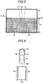
Fig. 5 is a view for explaining a method of specifying a vanishing point in a captured image in the reference state; -
Fig. 6 is a plan view for explaining setting of a target parking frame in the reference state; -
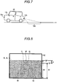
Fig. 7 is a side view of the vehicle in a state deviated from the reference state; -
Fig. 8 is a view for explaining deviation of the vanishing point in the captured image in the state deviated from the reference state; -
Fig. 9 is a plan view for explaining correction of the target parking frame in the state deviated from the reference state; -
Fig. 10 is a table illustrating an example of a correction table; -
Fig. 11 is a flowchart of an assistance processing executed by a processing unit according to the first embodiment; and -
Fig. 12 is a flowchart of an assistance processing executed by a processing unit according to a second embodiment. - Hereinafter, the same reference numerals will be given to the same constituent elements of following exemplary embodiments and the like, and a redundant description thereof will be appropriately omitted.
-
Fig. 1 is a view illustrating avehicle 10 in a first embodiment. Thevehicle 10 may be, for example, an automobile using an internal combustion engine (an engine) (not illustrated) as a drive source (an internal combustion engine automobile), an automobile using an electric motor (a motor) (not illustrated) as a drive source (an electric automobile, a fuel cell automobile, etc.), or an automobile using both of them as drive sources (a hybrid automobile). In addition, thevehicle 10 may be equipped with various transmission devices, and may be equipped with various devices (systems, elements, etc.) required to drive the internal combustion engine or the electric motor. In addition, the type, the number, the layout, and the like of devices involved in the driving ofwheels 13 in thevehicle 10 may be set in various ways. - As illustrated in
Fig. 1 , thevehicle 10 includes avehicle body 12, a plurality of (e.g., four)wheels 13, one or a plurality of (e.g., four)imaging units monitor device 16. When it is not necessary to distinguish theimaging units - The
vehicle body 12 forms avehicle room 12a in which an occupant rides. Thevehicle body 12 holds thewheels 13 and accommodates the imaging unit 14 and themonitor device 16 in thevehicle room 12a. - The imaging unit 14 is, for example, a digital camera incorporating an imaging element such as a charge coupled device (CCD) or a CMOS image sensor (CIS). The imaging unit 14 outputs, as captured image data, still image data or video image data including a plurality of frame images generated at a predetermined frame rate. Each imaging unit 14 has a wide-angle lens or a fish-eye lens, and is capable of imaging a range from 140° to 190° in the horizontal direction. The optical axis of the imaging unit 14 is set obliquely downward. Thus, the imaging unit 14 generates and outputs captured image data obtained by imaging the surroundings of the
vehicle 10 including a surrounding road surface. For example, in a parking space, the imaging unit 14 generates a captured image including an image of lane markings, which are a pair of lines parallel to each other. - The imaging units 14 are provided around the
vehicle body 12. For example, animaging unit 14a is provided at a transversely central portion of the front end portion of the vehicle body 12 (e.g., a front bumper). Theimaging unit 14a generates a captured image obtained by imaging the surroundings in front of thevehicle 10. Animaging unit 14b is provided at a transversely central portion of the rear end portion of the vehicle body 12 (e.g., a rear bumper). Theimaging unit 14b generates a captured image obtained by imaging the surroundings in rear of thevehicle 10. Animaging unit 14c is provided at a longitudinally central portion of the left end portion of the vehicle body 12 (e.g., a leftside view mirror 12b). Theimaging unit 14c generates a captured image obtained by imaging the surroundings on the left of thevehicle 10. Animaging unit 14d is provided at a longitudinally central portion of the right end portion of the vehicle body 12 (e.g., a rightside view mirror 12c). Theimaging unit 14d generates a captured image obtained by imaging the surroundings on the right of thevehicle 10. - The
monitor device 16 is provided within thevehicle room 12a at a position, which is visible to an occupant, for example, on a dashboard in front of a seat. Themonitor device 16 displays an image, outputs sound, and receives an operation of the occupant. -
Fig. 2 is a block diagram for explaining a configuration of anassistance apparatus 20 mounted on thevehicle 10. Theassistance apparatus 20 corrects, based on a captured image obtained by the imaging unit 14, a correction target such as deviation of an image caused by the inclination of the optical axis of the imaging unit 14, or the like, due to the inclination of thevehicle 10 or a vehicle height, which is the height of thevehicle 10. As illustrated inFig. 2 , theassistance apparatus 20 includes the imaging units 14, themonitor device 16, aninformation processing device 22, and an in-vehicle network 24. - The
monitor device 16 includes adisplay unit 40, asound output unit 42, and anoperation input unit 44. - The
display unit 40 displays an image based on image data transmitted from theinformation processing device 22. Thedisplay unit 40 is, for example, a display device such as a liquid crystal display (LCD) or an organic electroluminescent (EL) display (OELD). Thedisplay unit 40 displays a captured image on which, for example, a parking target area, which is a target position of thevehicle 10 to be parked, is superimposed. - The
sound output unit 42 outputs sound based on sound data transmitted from theinformation processing device 22. Thesound output unit 42 is, for example, a speaker. Thesound output unit 42 may be provided in the vehicle room at a position different from that of thedisplay unit 40. - The
operation input unit 44 receives an input from an occupant. Theoperation input unit 44 is, for example, a touch panel. Theoperation input unit 44 is provided on a display screen of thedisplay unit 40. Theoperation input unit 44 is configured to be able to transmit an image displayed by thedisplay unit 40. Thus, theoperation input unit 44 allows the occupant to visually recognize an image displayed on the display screen of thedisplay unit 40. Theoperation input unit 44 receives an instruction input when the occupant touches a position corresponding to the image displayed on the display screen of thedisplay unit 40, and transmits the instruction to theinformation processing device 22. - The
information processing device 22 is a computer including a microcomputer such as an electronic control unit (ECU). Theinformation processing device 22 acquires captured image data from the imaging unit 14. Theinformation processing device 22 transmits data about an image or sound generated based on the captured image or the like to themonitor device 16. Theinformation processing device 22 includes a central processing unit (CPU) 36a, a read only memory (ROM) 36b, a random access memory (RAM) 36c, adisplay controller 36d, asound controller 36e, and a solid state drive (SSD) 36f. In the present embodiment, theinformation processing device 22 manages assistance processing for thevehicle 10 by cooperation of hardware and software (control program). TheCPU 36a, theROM 36b, and theRAM 36c may be integrated in the same package. - The
CPU 36a is an example of a hardware processor and reads a program stored in a nonvolatile storage device such as theROM 36b to execute various calculation processings and controls based on the program. - The
ROM 36b stores individual programs, parameters, and the like required to execute the programs. TheRAM 36c temporarily stores various data for use in calculation by theCPU 36a. Thedisplay controller 36d mainly executes processing of an image obtained by the imaging unit 14, data conversion of a display image to be displayed on thedisplay unit 40, or the like, among the calculation processings by theinformation processing device 22. Thesound controller 36e mainly executes processing of sound to be output by thesound output unit 42, among the calculation processings by theinformation processing device 22. TheSSD 36f is a rewritable nonvolatile storage unit and preserves data even when a power supply of theinformation processing device 22 is turned off. - The in-
vehicle network 24 is, for example, a controller area network (CAN). The in-vehicle network 24 electrically interconnects theinformation processing device 22 and theoperation input unit 44 so as to enable them to mutually transmit and receive signals and information. -
Fig. 3 is a functional block diagram for explaining a function of theinformation processing device 22. As illustrated inFig. 3 , theinformation processing device 22 includes aprocessing unit 50 and astorage unit 52. - The
processing unit 50 is implemented, for example, as a function for theCPU 36a. Theprocessing unit 50 may be a hardware processor other than theCPU 36a. Theprocessing unit 50 includes a specifyingunit 54 and acorrection unit 56. Theprocessing unit 50 may implement the functions of the specifyingunit 54 and the correctingunit 56 by reading anassistance program 58 stored in thestorage unit 52. The specifyingunit 54 and thecorrection unit 56 may be partially or entirely constituted by hardware such as a circuit including an application specific integrated circuit (ASIC). Theprocessing unit 50 specifies the position (e.g., the position in the vertical direction) of a vanishing point in a captured image of the surroundings of thevehicle 10 acquired from the imaging unit 14, and corrects deviation of a correction target based on the specified position of the vanishing point and a preset reference value, thereby assisting driving of thevehicle 10. The reference value indicates the position of a vanishing point specified in a captured image that is obtained of thevehicle 10 in a reference state by the imaging unit 14. That is, the reference value is a value that indicates the reference position of the vanishing point. The correction target is, for example, the position of an image (e.g., an image of a target parking frame described later), which results from vehicle height, vehicle inclination, the optical axis of the imaging unit 14, and deviation of the optical axis of the imaging unit 14, to be superimposed on the captured image. - The specifying
unit 54 processes the captured image acquired from the imaging unit 14. For example, the specifyingunit 54 sets a position in the captured image on which the target parking frame, which is an area where thevehicle 10 is to be parked, is to be superimposed, and generates a display image, which is to be displayed on thedisplay unit 40 for assisting parking, by superimposing the target parking frame on the captured image. Incidentally, an occupant such as a driver instructs parking assistance by touching theoperation input unit 44 on the target parking frame. The specifyingunit 54 acquires the captured image including an image of a pair of lines parallel to each other in the real world (e.g., lane markings of a parking space) from the imaging unit 14. The specifyingunit 54 detects the pair of parallel lines in the captured image by a technique such as edge detection, thereby specifying the position of a vanishing point, at which extension lines of the pair of parallel lines intersect each other in the captured image, based on the pair of detected parallel lines. - The
correction unit 56 corrects deviation of the correction target based on the reference value and the position of the vanishing point in the captured image specified by the specifyingunit 54. For example, thecorrection unit 56 corrects deviation of the correction target based on the difference between the position of the vanishing point and the reference value. Specifically, thecorrection unit 56 corrects the correction target, which results from deviation of the height or inclination of the vehicle from the reference state, based on a correction table 60 in which differences are associated with correction values. - The
storage unit 52 is implemented as functions for theROM 36b, theRAM 36c, theSSD 36f, and the like. Thestorage unit 52 stores theassistance program 58 to be executed by theprocessing unit 50, a reference value SV, and the correction table 60, which are required for the execution of theassistance program 58, and the like. -
Figs. 4 to 6 are views for explaining the reference state.Fig. 4 is a side view of thevehicle 10 in the reference state.Fig. 5 is a view for explaining a method of specifying a vanishing point VP in a capturedimage 92 in the reference state.Fig. 6 is a plan view for explaining setting of a target parking frame PAa in the reference state. - The reference state is, for example, a state in which no occupant rides on the
vehicle 10 and no baggage is loaded on thevehicle 10. Therefore, thevehicle 10 in the reference state has a reference height (e.g., the maximum vehicle height) and is in a state where thevehicle 10 is almost not inclined. Incidentally, the reference state may be set as appropriate. - As illustrated in
Fig. 4 , in the reference state, theimaging unit 14b generates the capturedimage 92, which is obtained by imaging an imaging area SAa of the surroundings of thevehicle 10. As illustrated inFig. 5 , the vanishing point VP in the reference state is, for example, a point at which extension lines EL of a pair of lane markings of a parking space, which are a pair ofparallel lines 90, intersect each other. A straight line passing through the vanishing point VP (e.g., a straight line parallel to the upper and lower sides of the captured image 92) is a vanishing line VL. When a horizontal line HL is included in the capturedimage 92, the vanishing line VL substantially coincides with the horizontal line HL. A reference value SV is the distance between the position SP of the vanishing point VP and the lower side of the capturedimage 92, and is specified in advance and stored in thestorage unit 52. The reference value SV may be in units of pixels. As illustrated inFig. 6 , in the reference state, thevehicle 10 has no vehicle height deviation or vehicle inclination deviation, and thus the specifyingunit 54 can set the target parking frame PAa to an appropriate position between the lane markings of the parking space, which are the pair ofparallel lines 90 included in the capturedimage 92. -
Figs. 7 to 9 are views for explaining correction of the correction target by theprocessing unit 50.Fig. 7 is a side view of thevehicle 10 in a state deviated from the reference state.Fig. 8 is a view for explaining deviation of the vanishing point VP in the capturedimage 92 in the state deviated from the reference state.Fig. 9 is a plan view for explaining correction of a target parking frame PAb in the state deviated from the reference state. - As illustrated in
Fig. 7 , an example of the state deviated from the reference state is a state in which thevehicle 10 has a reduced height at the rear end portion and thevehicle 10 is inclined. In this inclined state, theimaging unit 14b generates the capturedimage 92, which is obtained by imaging an imaging area SAb of the surroundings of thevehicle 10. The distance from thevehicle 10 to the imaging area SAb and the size of the imaging area SAb are different from the distance to the imaging area SAa and the size of the imaging area SAa in the reference state. As illustrated inFig. 8 , in the state deviated from the reference state, the specifyingunit 54 detects the vanishing point VP at a position DP different from that of the vanishing point VP in the reference state. The specifyingunit 54 specifies a correction target value AV, which is the distance from the lower side of the capturedimage 92 to the vanishing point VP, as information on the position DP of the vanishing point VP. The correction target value AV may be in units of pixels. Thecorrection unit 56 calculates the difference Δ between the correction target value AV and the reference value SV. As illustrated inFig. 9 , in the deviated state, the target parking frame PAb, which is set in the capturedimage 92 by the specifyingunit 54, is deviated in the longitudinal direction of thevehicle 10 from the position between the pair ofparallel lines 90 in the real world. Thecorrection unit 56 corrects the target parking frame PAb based on the difference Δ, thereby setting a target parking frame PAc at an appropriate position between the lane markings. -
Fig. 10 is a table illustrating an example of the correction table 60. - As illustrated in
Fig. 10 , the correction table 60 associates the difference Δn between the reference value SV and the correction target value AV with correction values for correction of the correction target. For example, the correction table 60 associates the difference Δ with vehicle height correction values HeAn (n=1, 2, ...) for correction of the vehicle height, inclination correction values SIAn for correction of the inclination of thevehicle 10, optical axis correction values AxAn for correction of the optical axis of a lens in the imaging unit 14, and image correction values PiAn for correction of the position of the target parking frame PAb to be superimposed on the capturedimage 92. Thecorrection unit 56 extracts a correction value associated with the calculated difference Δ and uses the value to correct the vehicle height, the inclination of thevehicle 10, the optical axis, the position in the capturedimage 92, or the like, which is the correction target. -
Fig. 11 is a flowchart of an assistance processing executed by theprocessing unit 50. Theprocessing unit 50 executes the assistance processing by reading theassistance program 58 stored in thestorage unit 52. - As illustrated in
Fig. 11 , in the assistance processing, the specifyingunit 54 acquires the capturedimage 92 from the imaging unit 14 (S1102). The specifyingunit 54 specifies the pair ofparallel lines 90 included in the capturedimage 92 by a technique such as edge detection (S1104). The specifyingunit 54 specifies the vanishing point VP at which the extension lines EL of the pair ofparallel lines 90 intersect each other, and outputs the correction target value AV, which is information on the position of the vanishing point VP in the capturedimage 92, to the correction unit 56 (S1106). - The
correction unit 56 calculates the difference Δ between the correction target value AV, which is information on the position of the vanishing point VP specified by the specifyingunit 54, and the reference value SV (S1112). Thecorrection unit 56 extracts and sets a correction value associated with the calculated difference Δ from the correction table 60 (S1114). Thecorrection unit 56 corrects the correction target based on the extracted correction value (S1116). For example, thecorrection unit 56 extracts an image correction value PiAn from the correction table 60, corrects the position of the target parking frame PAb, which is to be superimposed on the capturedimage 92, based on the image correction value PiAn, and causes a display image, which is generated by the correction, to be displayed on thedisplay unit 40, thereby assisting the driver to park. The assistance processing is completed in this way. - As described above, in the
assistance apparatus 20, theprocessing unit 50 specifies the vanishing point VP of the pair ofparallel lines 90 included in the capturedimage 92 acquired from the imaging unit 14, and corrects the correction target based on the correction value set based on the vanishing point VP and the reference value SV. As described above, theassistance apparatus 20 corrects the correction target based on the capturedimage 92, whereby it is not necessary to separately provide a sensor such as a vehicle height sensor, so that deviation of the correction target caused by a change in the vehicle height, the inclination of thevehicle 10, or the like can be corrected with a less complicated configuration. - As described above, the
assistance apparatus 20 corrects the correction target by specifying the vanishing point VP based on the pair ofparallel lines 90. Thus, even in an environment where it is difficult to place the horizontal line HL in the capturedimage 92, such as a parking space, theassistance apparatus 20 can correct the correction target by specifying the vanishing point VP based on the pair ofparallel lines 90. - Next, a second embodiment in which the above-described assistance processing is partially modified will be described. In the second embodiment, the specifying
unit 54 specifies positions of a plurality of vanishing points VP from a plurality of capturedimages 92. The specifyingunit 54 outputs, as an average vanishing point VP position, the average value of a plurality of correction target values AV, which indicate the positions of the plurality of vanishing points VP, to thecorrection unit 56. Thecorrection unit 56 corrects the correction target based on the reference value SV and the average value of the correction target values AV. For example, thecorrection unit 56 may correct the correction target by calculating the difference Δ between the average value of the correction target values AV and the reference value SV and extracting a correction value associated with the difference Δ from the correction table 60. -
Fig. 12 is a flowchart of an assistance processing executed by the processing unit of the second embodiment. In the processing of the second embodiment, a description related to the same processing as that of the first embodiment will be omitted or simplified. - As illustrated in
Fig. 12 , the specifyingunit 54 executes steps S1102 to S1106. The specifyingunit 54 determines whether or not the number of specified vanishing points VP is a predetermined number (S1108). When it is determined that the number of specified vanishing points VP is not the predetermined number (S1108: No), the specifyingunit 54 repeats the process after step S1102. When it is determined that the number of specified vanishing points VP has reached the predetermined number (S1108: Yes), the specifyingunit 54 calculates the average value (e.g., the arithmetic average value) of the vertical positions (i.e., the correction target values AV) of the predetermined number of varnishing points VP, and outputs, to thecorrection unit 56, the average value as information on the positions of the vanishing points VP (S1110). - The
correction unit 56 calculates the difference Δ between the average value of the correction target values AV, which indicate the positions of the plurality of vanishing points VP, and the reference value SV (S1112), and executes step S1114 and the following process based on the difference Δ. - As described above, the
assistance apparatus 20 of the second embodiment can increase the accuracy of correction since it specifies a plurality of vanishing points VP and corrects the correction target based on the difference between the average value of the correction target values AV, which is the average of the plurality of vanishing points VP, and the reference value SV. - The function, connection relationship, number, arrangement, and the like of the elements in each embodiment described above may be appropriately changed, deleted, and so on within the scope of the disclosure and the scope equivalent to the scope of the disclosure. Individual embodiments may also be appropriately combined with each other. The order of individual steps in each embodiment may be appropriately changed.
- For example, the above-described embodiment shows an example in which the specifying
unit 54 specifies the vanishing point VP, but this disclosure is not limited thereto. The specifyingunit 54 may specify the horizontal line HL or the vanishing line VL. For example, the specifyingunit 54 may acquire a captured image including the horizontal line HL from the imaging unit 14, and may specify the horizontal line HL by a technique such as edge detection. In addition, the specifyingunit 54 may acquire a captured image including a pair of parallel lines, and may specify a vanishing line, which is a straight line including a point (i.e., a vanishing point VP) at which extension lines of the pair of parallel lines intersect each other within the captured image, based on the pair of parallel lines. In this case, thecorrection unit 56 may correct the correction target based on the difference Δ between the position of the horizontal line HL or the vanishing line VL and the preset reference value SV. Even in this case, the specifyingunit 54 may specify a plurality of horizontal lines HL or vanishing lines VL from a plurality of captured images, and thecorrection unit 56 may correct the correction target based on the reference value and the average of the positions of the horizontal lines HL or the vanishing lines VL. - The above-described embodiments show an example in which the
correction unit 56 corrects the correction target based on the difference between the position of the vanishing point VP, the vanishing line VL, or the horizontal line HL and the reference value, but this disclosure is not limited thereto. For example, thecorrection unit 56 may correct the correction target based on the ratio between the position of the vanishing point VP, the vanishing line VL, or the horizontal line HL and the reference value. - The principles, preferred embodiment and mode of operation of the present invention have been described in the foregoing specification. However, the invention which is intended to be protected is not to be construed as limited to the particular embodiments disclosed. Further, the embodiments described herein are to be regarded as illustrative rather than restrictive. Variations and changes may be made by others, and equivalents employed, without departing from the scope of the present invention. Accordingly, it is expressly intended that all such variations, changes and equivalents which fall within the scope of the present invention as defined in the claims, be embraced thereby.
Claims (5)
- An assistance apparatus (20) comprising:an imaging unit (14a, 14b, 14c, 14d) that is configured to capture an image of a surrounding of a vehicle (10) to generate a captured image (92); anda processing unit (50) that is configured to correct deviation of a correction target based on a preset reference value (SV) and a position of a vanishing point (VP), a vanishing line (VL), or a horizontal line (HL) specified in the captured image (92) to assist driving of the vehicle (10).
- The assistance apparatus according to claim 1,
wherein the processing unit (50) is configured to acquire the captured image (92) including an image of a pair of parallel lines (90), which are parallel to each other, and to specify the position of the vanishing point (VP) or the vanishing line (VL) based on the pair of parallel lines (90). - The assistance apparatus according to claim 2, configured to assist a driver to park the vehicle (10), wherein the pair of parallel lines (90) are lane markings of a parking space.
- The assistance apparatus according to any one of claims 1 to 3,
wherein the processing unit (50) is configured to specify positions of a plurality of vanishing points (VP), vanishing lines (VL), or horizontal lines (HL) from a plurality of the captured images (92), and to correct the correction target based on the reference value (SV) and an average of the positions of the plurality of horizontal lines (HL), vanishing lines (VL), or vanishing points (VP). - The assistance apparatus according to any one of claims 1 to 4,
wherein the correction target includes at least one of a vehicle height, an inclination of the vehicle, an optical axis of a lens in the imaging unit (14a, 14b, 14c, 14d), and a position of a target parking frame (PAc) to be superimposed on the captured image (92).
Applications Claiming Priority (1)
| Application Number | Priority Date | Filing Date | Title |
|---|---|---|---|
| JP2017063012A JP2018165912A (en) | 2017-03-28 | 2017-03-28 | Support apparatus |
Publications (2)
| Publication Number | Publication Date |
|---|---|
| EP3382604A2 true EP3382604A2 (en) | 2018-10-03 |
| EP3382604A3 EP3382604A3 (en) | 2018-11-14 |
Family
ID=62017148
Family Applications (1)
| Application Number | Title | Priority Date | Filing Date |
|---|---|---|---|
| EP18164650.6A Withdrawn EP3382604A3 (en) | 2017-03-28 | 2018-03-28 | Assistance apparatus |
Country Status (3)
| Country | Link |
|---|---|
| US (1) | US20180288371A1 (en) |
| EP (1) | EP3382604A3 (en) |
| JP (1) | JP2018165912A (en) |
Families Citing this family (8)
| Publication number | Priority date | Publication date | Assignee | Title |
|---|---|---|---|---|
| US11989951B2 (en) * | 2020-04-30 | 2024-05-21 | Boe Technology Group Co., Ltd. | Parking detection method, system, processing device and storage medium |
| CN115190236B (en) * | 2021-04-07 | 2024-05-28 | 深圳市万普拉斯科技有限公司 | Image shooting method, device, computer equipment and storage medium |
| JP7340802B2 (en) * | 2021-09-30 | 2023-09-08 | パナソニックIpマネジメント株式会社 | Parking support device, parking support method, and vehicle |
| JP7718279B2 (en) * | 2022-01-17 | 2025-08-05 | トヨタ自動車株式会社 | Wrong-way driving detection method and wrong-way driving detection device |
| CN114708571A (en) * | 2022-03-07 | 2022-07-05 | 深圳市德驰微视技术有限公司 | Parking space marking method and device for automatic parking based on domain controller platform |
| KR20230168859A (en) * | 2022-06-08 | 2023-12-15 | 현대모비스 주식회사 | Vehicle lighting device and method of operating thereof |
| JP7841985B2 (en) * | 2022-08-15 | 2026-04-07 | トヨタ自動車株式会社 | Vehicle display device |
| JP7512330B2 (en) * | 2022-08-19 | 2024-07-08 | 株式会社デンソーテン | Information processing device, information processing method, and program |
Citations (1)
| Publication number | Priority date | Publication date | Assignee | Title |
|---|---|---|---|---|
| JP2005075015A (en) | 2003-08-29 | 2005-03-24 | Toyota Motor Corp | Guidance support device |
Family Cites Families (3)
| Publication number | Priority date | Publication date | Assignee | Title |
|---|---|---|---|---|
| US20110115912A1 (en) * | 2007-08-31 | 2011-05-19 | Valeo Schalter Und Sensoren Gmbh | Method and system for online calibration of a video system |
| JP2014228943A (en) * | 2013-05-20 | 2014-12-08 | 日本電産エレシス株式会社 | Vehicular external environment sensing device, and axial shift correction program and method therefor |
| JP2015215299A (en) * | 2014-05-13 | 2015-12-03 | 株式会社デンソー | Object position estimation device |
-
2017
- 2017-03-28 JP JP2017063012A patent/JP2018165912A/en active Pending
-
2018
- 2018-02-27 US US15/906,105 patent/US20180288371A1/en not_active Abandoned
- 2018-03-28 EP EP18164650.6A patent/EP3382604A3/en not_active Withdrawn
Patent Citations (1)
| Publication number | Priority date | Publication date | Assignee | Title |
|---|---|---|---|---|
| JP2005075015A (en) | 2003-08-29 | 2005-03-24 | Toyota Motor Corp | Guidance support device |
Also Published As
| Publication number | Publication date |
|---|---|
| US20180288371A1 (en) | 2018-10-04 |
| JP2018165912A (en) | 2018-10-25 |
| EP3382604A3 (en) | 2018-11-14 |
Similar Documents
| Publication | Publication Date | Title |
|---|---|---|
| EP3382604A2 (en) | Assistance apparatus | |
| US10308283B2 (en) | Parking assist apparatus | |
| US9895974B2 (en) | Vehicle control apparatus | |
| JP6028848B2 (en) | Vehicle control apparatus and program | |
| US8498770B2 (en) | Vehicle parking assist system and method | |
| US10855954B2 (en) | Periphery monitoring device | |
| US9994157B2 (en) | Periphery monitoring apparatus and periphery monitoring system | |
| EP3547677B1 (en) | Bird's eye view image generation device, bird's eye view image generation system, bird's eye view image generation method and program | |
| JP7039879B2 (en) | Display control device | |
| US11017245B2 (en) | Parking assist apparatus | |
| JP7000383B2 (en) | Image processing device and image processing method | |
| JP2010226449A (en) | Obstacle detection device | |
| WO2019058585A1 (en) | Display control device | |
| US20190126827A1 (en) | Image generating apparatus and program | |
| US11091096B2 (en) | Periphery monitoring device | |
| CN107113402A (en) | image processing system and image processing apparatus | |
| JP2012166689A (en) | Driving assistance apparatus | |
| US20200148222A1 (en) | Driving support device | |
| JP2014126918A (en) | Camera module, camera system and image display method | |
| JP2006298217A (en) | Vehicle periphery monitoring device | |
| JP2019114965A (en) | Image processing apparatus | |
| JP2019135127A (en) | Parking support device |
Legal Events
| Date | Code | Title | Description |
|---|---|---|---|
| PUAI | Public reference made under article 153(3) epc to a published international application that has entered the european phase |
Free format text: ORIGINAL CODE: 0009012 |
|
| STAA | Information on the status of an ep patent application or granted ep patent |
Free format text: STATUS: THE APPLICATION HAS BEEN PUBLISHED |
|
| AK | Designated contracting states |
Kind code of ref document: A2 Designated state(s): AL AT BE BG CH CY CZ DE DK EE ES FI FR GB GR HR HU IE IS IT LI LT LU LV MC MK MT NL NO PL PT RO RS SE SI SK SM TR |
|
| AX | Request for extension of the european patent |
Extension state: BA ME |
|
| PUAL | Search report despatched |
Free format text: ORIGINAL CODE: 0009013 |
|
| AK | Designated contracting states |
Kind code of ref document: A3 Designated state(s): AL AT BE BG CH CY CZ DE DK EE ES FI FR GB GR HR HU IE IS IT LI LT LU LV MC MK MT NL NO PL PT RO RS SE SI SK SM TR |
|
| AX | Request for extension of the european patent |
Extension state: BA ME |
|
| RIC1 | Information provided on ipc code assigned before grant |
Ipc: G06K 9/00 20060101AFI20181005BHEP |
|
| STAA | Information on the status of an ep patent application or granted ep patent |
Free format text: STATUS: REQUEST FOR EXAMINATION WAS MADE |
|
| 17P | Request for examination filed |
Effective date: 20190322 |
|
| RBV | Designated contracting states (corrected) |
Designated state(s): AL AT BE BG CH CY CZ DE DK EE ES FI FR GB GR HR HU IE IS IT LI LT LU LV MC MK MT NL NO PL PT RO RS SE SI SK SM TR |
|
| STAA | Information on the status of an ep patent application or granted ep patent |
Free format text: STATUS: EXAMINATION IS IN PROGRESS |
|
| STAA | Information on the status of an ep patent application or granted ep patent |
Free format text: STATUS: THE APPLICATION HAS BEEN WITHDRAWN |
|
| 17Q | First examination report despatched |
Effective date: 20210318 |
|
| 18W | Application withdrawn |
Effective date: 20210322 |