EP3382474A1 - Information processing apparatus, information processing system, and information processing method - Google Patents
Information processing apparatus, information processing system, and information processing method Download PDFInfo
- Publication number
- EP3382474A1 EP3382474A1 EP18160685.6A EP18160685A EP3382474A1 EP 3382474 A1 EP3382474 A1 EP 3382474A1 EP 18160685 A EP18160685 A EP 18160685A EP 3382474 A1 EP3382474 A1 EP 3382474A1
- Authority
- EP
- European Patent Office
- Prior art keywords
- speaker
- information processing
- information
- playback device
- sound
- Prior art date
- Legal status (The legal status is an assumption and is not a legal conclusion. Google has not performed a legal analysis and makes no representation as to the accuracy of the status listed.)
- Granted
Links
Images


Classifications
-
- G—PHYSICS
- G04—HOROLOGY
- G04G—ELECTRONIC TIME-PIECES
- G04G13/00—Producing acoustic time signals
- G04G13/02—Producing acoustic time signals at preselected times, e.g. alarm clocks
-
- G—PHYSICS
- G06—COMPUTING OR CALCULATING; COUNTING
- G06F—ELECTRIC DIGITAL DATA PROCESSING
- G06F3/00—Input arrangements for transferring data to be processed into a form capable of being handled by the computer; Output arrangements for transferring data from processing unit to output unit, e.g. interface arrangements
- G06F3/16—Sound input; Sound output
- G06F3/165—Management of the audio stream, e.g. setting of volume, audio stream path
-
- G—PHYSICS
- G08—SIGNALLING
- G08B—SIGNALLING SYSTEMS, e.g. PERSONAL CALLING SYSTEMS; ORDER TELEGRAPHS; ALARM SYSTEMS
- G08B3/00—Audible signalling systems, e.g. audible personal calling systems
- G08B3/10—Audible signalling systems, e.g. audible personal calling systems using electric transmission; using electromagnetic transmission
- G08B3/1008—Personal calling arrangements or devices, i.e. paging systems
- G08B3/1016—Personal calling arrangements or devices, i.e. paging systems using wireless transmission
-
- H—ELECTRICITY
- H04—ELECTRIC COMMUNICATION TECHNIQUE
- H04R—LOUDSPEAKERS, MICROPHONES, GRAMOPHONE PICK-UPS OR LIKE ACOUSTIC ELECTROMECHANICAL TRANSDUCERS; ELECTRIC HEARING AIDS; PUBLIC ADDRESS SYSTEMS
- H04R3/00—Circuits for transducers
- H04R3/12—Circuits for transducers for distributing signals to two or more loudspeakers
Definitions
- a preferred embodiment of the present invention relates to an information processing apparatus, an information processing system, and an information processing method that are related to an alarm function.
- an object of a preferred embodiment of the present invention is to provide an information processing apparatus, an information processing system, and an information processing method that are able to achieve an alarm function even when a device that does not seem to have an alarm function is used as a playback device.
- An information processing apparatus includes an acquisition portion that acquires event information as a trigger; and a transmission portion that transmits first instruction information that causes a predetermined sound to be played or play data that causes a predetermined sound to be played, to a playback device, at timing on a basis of the event information acquired by the acquisition portion.
- a predetermined sound is able to be played at timing on the basis of an instruction of a user.
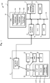
- Fig. 1 is a block diagram illustrating a hardware configuration of an information processing system 100 according to a first preferred embodiment of the present invention. It is to be noted that the configuration of the information processing system illustrated below is merely an example, is not limited to this configuration, and is able to be appropriately changed according to specifications.
- the information processing system 100 is provided with an AV receiver 1 and a speaker 2.
- the AV receiver 1 corresponds to the information processing apparatus of the present invention
- the speaker 2 corresponds to the playback device of the present invention.
- the information processing apparatus is able to be implemented by not only the AV receiver but also a speaker provided with a CPU and a DSP, for example, a personal computer, or the like.
- the playback device is able to be implemented by not only a speaker but also anything that is able to play a sound.
- the speaker 2 is provided with a network module 20, a D/A converter 21, an amplifier 22, a speaker unit 23, an MCU (Micro Controller Unit) 24, and a key 25.
- a network module 20 a D/A converter 21, an amplifier 22, a speaker unit 23, an MCU (Micro Controller Unit) 24, and a key 25.
- the MCU 24 reads a program and the like that are stored in a memory inside the MCU 24, and executes various control processing.
- the network module 20 is an interface that performs transmission and reception of data with the AV receiver 1. As a result, the speaker 2 is able to perform the transmission and reception of data with the AV receiver 1 through the network module 20.
- the MCU 24 decodes audio data transmitted from the network module 20, and outputs a digital signal.
- the D/A converter 21 converts the digital signal into an analog signal.
- the amplifier 22 inputs the analog signal converted by the D/A converter 21.
- the MCU 24 is also able to read the audio data (audio data of a beep sound, for example) stored in a not-shown flash memory and input a digital signal of the beep sound into the D/A converter 21.
- the MCU 24 is also able to instruct the DSP provided in the speaker 2, generate a digital signal of an alarm sound, and input the digital signal into the D/A converter 21.
- the amplifier 22 amplifies a supplied analog signal and outputs an amplified signal to the speaker unit 23.
- the speaker unit 23 emits a sound according to a signal supplied from the amplifier 22.
- the key 25 is an operation portion provided in the speaker 2, and, for example, includes a stop button 251, a pause button 252, a volume control button 253, and the like. It is to be noted that the key 25 is not limited to the stop button 251, the pause button 252, and the volume control button 253, but also includes the operation portion provided in the speaker 2.
- operation information corresponding to an operated operation portion is transmitted to the MCU 24.
- the MCU 24 transmits the operation information acquired through the network module 20 to the AV receiver 1.
- the AV receiver 1 is provided with a CPU 10, a ROM 11, a RAM 12 and a DSP (Digital Signal Processor) 14, a network module 15, and an RTC (Real Time Clock) 16 that are connected through a bus 18.
- the ROM 11 stores a sound source 111.
- the CPU 10 controls each portion of the AV receiver 1.
- the ROM 11 is a flash memory, for example, and stores various programs for the DSP 14, data for the DSP 14, a firmware program that manages the basic operations of the AV receiver 1, various control programs, and the like.
- the CPU 10 reads a program and the like that are stored in the ROM 11, and executes various control processing.
- the RAM 12 stores various data temporarily and functions as a working area. It is to be noted that various control programs may be recorded in other recording media (an optical disk, a magnetic disk, or the like) that can be read by the AV receiver 1.
- the ROM 11 is able to store the audio data acquired from an external device.
- the DSP 14, under the control of the CPU 10, reads a program or data for the DSP stored in the ROM 11, and performs various processing such as adding an effect to the audio data read from the ROM 11.
- the CPU 10 is able to control the DSP 14 to generate an audio digital signal.
- the CPU 10 outputs the audio signal to which effect addition, signal generation, or the like is performed by the DSP 14, to the network module 15.
- the network module 15 is an interface that transmits and receives data to and from an external device such as a speaker 2.
- the transmission and reception of data is able to be performed between devices such as various external drive devices, an audio device, or a personal computer through the network module 15.
- the AV receiver 1 is able to perform the transmission and reception of data between devices connected to a communication network such as a LAN (Local Area Network) through the network module 15.
- a communication network such as a LAN (Local Area Network) through the network module 15.
- the network may be constructed by either wired or wireless connections.
- the ROM 11 stores a sound source 111.
- the sound source 111 is what is called audio data, and includes, for example, various types of sounds such as music, a conversation sound, an alarm sound, a noise sound, or a beep sound.
- the RTC 16 has a clock function.
- the RTC 16 transmits time information to the CPU 10. As a result, the CPU 10 is able to acquire time information at any time.
- the CPU 10 issues various instructions based on the information that has been input through the network module 15 and the time information that has been transmitted from the RTC 16.
- the information that the AV receiver 1 transmits is instruction information for causing the speaker 2 to play a predetermined sound.
- the CPU 10 is provided with an acquisition portion 141, a transmission portion 142, and a reception portion 143.
- the acquisition portion 141 acquires event information as a trigger.
- a user inputs the event information from the outside to the AV receiver 1 through the network module 15.
- the user inputs the event information by using application software installed in a not-shown smartphone or a personal computer that is able to communicate with the AV receiver 1.
- the acquisition portion 141 acquires the event information that has been input by the user, through the network module 15.
- the event information includes, for example, not only date and time and a start time to cause the speaker 2 to play a predetermined sound but also information such as an event, the weather, or a temperature.
- the transmission portion 142 transmits a play instruction (first instruction information) that causes a predetermined sound to be played at timing on the basis of the event information acquired by the acquisition portion 141, to the speaker 2.
- the play instruction is an example of the first instruction information of the present invention.
- the CPU 10 when receiving event information, checks timing (T1) on the basis of the event information against current time information that is able to be acquired at any time from the RTC 16.
- the timing (T1) is time information such as date and time when an alarm is generated by the speaker 2.
- the transmission portion 142 of the CPU 10 transmits a play instruction to the speaker 2.
- a predetermined sound a beep sound, for example
- the speaker 2 plays a predetermined sound at timing on the basis of event information. Therefore, even when the speaker 2 does not have an alarm function, the alarm function is able to be achieved in the speaker 2.
- a predetermined sound may be a sound originally stored in the speaker 2.
- the speaker 2 plays a sound stored in an own device.
- the speaker 2 is able to play sound information transmitted from the sound source 111 of the AV receiver 1.
- the CPU 10 selects audio data of a type on the basis of the event information acquired by the acquisition portion 141, from the sound source 111.
- the transmission portion 142 transmits selected audio data to the speaker 2.
- a sound that is not stored in the speaker 2 is able to be played.
- the music transmitted from the sound source 111 of the AV receiver 1 is able to be played.
- the alarm function is able to be achieved by playing the sound information transmitted from the sound source 111 of the AV receiver 1.
- the reception portion 143 receives a predetermined command from the speaker 2.
- the predetermined command is transmitted from the speaker 2 to the AV receiver 1, for example, when a user operates the operation portion of either of the keys 25 of the speaker 2.
- the reception portion 143 of the AV receiver 1 receives the predetermined command corresponding to the operation portion transmitted from the speaker 2.
- a stop command is transmitted to the reception portion 143 of the AV receiver 1.
- the CPU 10 transmits a stop instruction (second instruction information) to the speaker 2 in response to the stop command.
- the stop instruction is an example of the second instruction information of the present invention.
- the transmission portion 142 transmits the stop instruction to the speaker 2.
- a pause command is transmitted to the reception portion 143 of the AV receiver 1.
- the CPU 10 in response to the pause command, transmits a pause instruction and then retransmits a play instruction (third instruction information) after a lapse of a certain time.
- the instruction to transmit a pause instruction and then play again after a lapse of a certain time is an example of the third instruction information on the present invention.
- the transmission portion 142 transmits a pause instruction to the speaker 2, and records a stop time (T2) in the RAM 12.
- the CPU 10 calculates timing (T3) in which a certain time elapses from the timing (T2) in which the speaker 2 has stopped playing.
- the CPU 10 checks the timing (T3) in which a certain time elapses from the timing (T2) in which the speaker 2 has stopped playing against current time information that is able to be acquired at any time from the RTC 16.
- the transmission portion 142 of the CPU 10 retransmits a play instruction to the speaker 2.
- the speaker 2 when receiving the play instruction, stops a predetermined sound being played and plays a predetermined sound again after a lapse of a certain time.
- the information processing system 100 is able to achieve what is called a snooze function.
- the sound that the speaker 2 plays again is not limited to the predetermined sound that has been played the first time and may be sound other than the predetermined sound.
- a volume control command is transmitted to the reception portion 143 of the AV receiver 1.
- the CPU 10 transmits a volume control instruction (fourth instruction information) to the speaker 2 in response to the volume control command.
- the volume control instruction is an example of the fourth instruction information of the present invention to change the volume of a predetermined sound.
- the transmission portion 142 that has received the instruction transmits the volume control instruction to the speaker 2.
- the amplifier 22 amplifies a supplied analog signal in accordance with the volume control instruction from the MCU 24 and outputs an amplified signal to the speaker unit 23.
- the speaker unit 23 emits a sound according to a signal supplied from the amplifier 22.
- the speaker 2 is able to emit a sound of which the volume has been controlled based on the volume control instruction.
- the speaker 2 plays a predetermined sound so as to increase the volume of the predetermined sound.
- the speaker 2 plays a predetermined sound so as to decrease the volume of the predetermined sound.
- the information processing system 100 is able to change the playing of a predetermined sound. It is to be noted that examples of change of a predetermined sound include intermittent playing or the change of playing speed, other than the change of the strength of a playing sound.
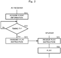
- Fig. 2 , Fig. 3 , Fig. 4 , and Fig. 5 are flow charts showing control performed by the information processing system 100.
- a description will be given of an information processing method in the information processing system 100.
- the acquisition portion 141 acquires event information as a trigger (S11).
- the CPU 10 checks timing (T1) on the basis of acquired event information against current time information that is able to be acquired at any time from the RTC 16.
- the transmission portion 142 transmits a play instruction that causes a predetermined sound to be played, to the speaker 2 (S13) .
- the speaker 2 when receiving the play instruction (S21), plays a predetermined sound (S22).
- the transmission portion 142 does not transmit the play instruction. Therefore, even when the speaker 2 does not seem to have an alarm function, since the speaker 2 is able to play a predetermined sound if the current time reaches the timing (T1), the alarm function is able to be achieved in the speaker 2.
- a predetermined command is input (S23).
- the reception portion 143 of the AV receiver 1 receives the predetermined command from the speaker 2 (S14).
- the CPU 10 determines whether or not an input command is a stop command (S15).
- the predetermined command is a stop command that indicates playing stop (S15: Yes)
- the transmission portion 142 of the AV receiver 1 transmits a stop instruction (second instruction information) to the speaker 2 (S16).
- the speaker 2 receives the stop instruction (S24), and the speaker 2 stops the playing of a predetermined sound being played (S25) .
- the predetermined command is not the second instruction information that indicates playing stop (S15: No)
- the CPU 10 shifts the current operation to a predetermined operation illustrated in Fig. 4 .
- the CPU 10 records a pause time (T2) in the RAM 12 in response to the pause command, and the transmission portion 142 transmits a stop instruction to the speaker 2 (S18) .
- the speaker 2 receives the stop instruction (S26), and the speaker 2 stops the playing of the predetermined sound being played (S27) .
- the CPU 10 shifts the current operation to a predetermined operation illustrated in Fig. 5 .
- the CPU 10 checks the timing (T3) in which a certain time elapses from the timing (T2) in which the speaker 2 has stopped playing against current time information that is able to be acquired at any time from the RTC 16.
- T3 the transmission portion 142 of the AV receiver 1 retransmits a play instruction to the speaker 2 (S20) .
- the speaker 2 receives the third instruction information (S28), and the speaker 2 plays a predetermined sound (S29) .
- the transmission portion 142 does not transmit the play instruction. As a result, what is called a snooze function is able to be achieved.
- a predetermined command is a sound change command (turn up the volume, for example) that indicates an instruction that changes a predetermined sound (S41: Yes)
- the transmission portion 142 of the AV receiver 1 transmits a volume control instruction (turn up the volume) to the speaker 2 (S42).
- the speaker 2 receives the volume control instruction (turn up the volume) (S30), and changes (turn up the volume) the predetermined sound being played (S31) .
- the predetermined command is not a sound change command (S41: No)
- the transmission portion 142 does not transmit an instruction to change a sound, to the speaker 2. Therefore, the speaker 2 keeps playing without changing the predetermined sound.
- the input of a command from the speaker 2 is able to change the playing of a predetermined sound of the speaker 2.
- the information processing system 200 according to the second preferred embodiment has the same configuration as an information processing system 100 according to the first preferred embodiment except that play data in addition to various instruction information is transmitted from the AV receiver 1 to the speaker 2. Therefore, the description of a configuration similar to the configuration of the information processing system 100 is omitted.
- the information processing system 100 according to the first preferred embodiment is referred to for a description of the information processing system 200 according to the second preferred embodiment.
- the acquisition portion 141 acquires the event information that has been transmitted by a user, through the network module 15.
- the CPU 10 selects data from the sound source 111 based on the event information acquired by the acquisition portion 141, and defines the data as play data.
- the transmission portion 142 transmits a play instruction (first instruction information) that causes a predetermined sound to be played at timing on the basis of the event information acquired by the acquisition portion 141, and the play data, to the speaker 2.
- first instruction information causes a predetermined sound to be played at timing on the basis of the event information acquired by the acquisition portion 141, and the play data, to the speaker 2.
- the speaker 2 plays the predetermined sound on the basis of the play data at timing on the basis of the event information. Therefore, even when the speaker 2 does not seem to have an alarm function, the alarm function is able to be achieved in the speaker 2.
- the CPU 10 when selecting the play data from the sound source 111, is able to simultaneously select a plurality of types of sounds from the sound source 111 as a predetermined sound.
- the CPU 10 is able to select, for example, an alarm sound that indicates that the current time reaches a predetermined time and music that indicates the weather of the day as play data from the sound source 111.
- the transmission portion 142 transmits selected play data to the speaker 2.
- the speaker 2 is able to play a plurality of types of sounds stored in the sound source 111 without reading the audio data stored in the memory of the MCU 24 of the speaker 2.
- the reception portion 143 of the AV receiver 1 receives a predetermined command. For example, in the case in which a user operates the stop button 251 of the speaker 2, a playing stop command is transmitted to the reception portion 143 of the AV receiver 1.
- the transmission portion 142 transmits a stop instruction to the speaker 2.
- the transmission portion 142 stops the transmission of the play data to the speaker 2.
- the play data is not transmitted from the AV receiver 1 to the speaker 2, and the MCU 24, when receiving the stop instruction transmitted from the AV receiver 1, stops a predetermined sound being played.
- the speaker 2 transmits a pause command to the reception portion 143 of the AV receiver 1.
- the transmission portion 142 transmits a stop instruction to the speaker 2.
- the transmission portion 142 stops the transmission of the play data to the speaker 2.
- the timing (T2) in which the speaker 2 has stopped playing reaches the timing (T3) in which a certain time elapses
- the transmission portion 142 retransmits a play instruction to the speaker 2.
- the transmission portion 142 transmits the play data to the speaker 2.
- the play data is retransmitted from the AV receiver 1 to the speaker 2, and the speaker 2 is able to play a predetermined sound at the timing (T3) .
- T3 timing
- a snooze function is able to be achieved in the speaker 2.
- Fig. 6 is a conceptual view illustrating an information processing system 300 according to a third preferred embodiment of the present invention.
- the information processing system 300 has the same configuration as the information processing system 100 or the information processing system 200 except that a plurality of speakers are included. Therefore, the description of a configuration similar to the configuration of the information processing system 100 or the information processing system 200 is omitted.
- the information processing system 300 is provided with the AV receiver 1 and a plurality of speakers 41, 42, 43, 44, and 45.
- the AV receiver 1 is connected to each of the plurality of speakers 41 to 45 through a communication network such as the Internet or the LAN (Local Area Network) and is able to mutually perform the transmission and reception of data.
- a communication network such as the Internet or the LAN (Local Area Network) and is able to mutually perform the transmission and reception of data.
- the network may be constructed by either wired or wireless connections.
- the AV receiver 1 transmits the first instruction information or play data that causes a predetermined sound of a different type to be played, to each of the plurality of speakers 41 to 45.
- the speakers 41 to 45 may be arranged in different rooms, respectively, and may be used by different users.
- the user individually inputs required event information to the AV receiver 1.
- the AV receiver 1 is able to play a predetermined sound on the basis of the event information that the user has input, in each of the speakers 41 to 45. Therefore, each of the speakers 41 to 45 is able to emit a different sound at a different time.
- the speakers 41 to 45 individually transmit a predetermined command to the reception portion 143 of the AV receiver 1. As a result, each of the speakers 41 to 45 is able to be operated.
- first modification example exemplifies the information processing method of the information processing system 100 in a case in which communication between the AV receiver 1 and the speaker 2 is normal
- first modification example enable the information processing system 100 to be adapted also to the case in which the communication between the AV receiver 1 and the speaker 2 is not normal.
- first to fourth modification examples a description is given of the first to fourth modification examples. It is to be noted that the description of a configuration similar to the configuration of the information processing method of the information processing system 100 is omitted.
- Fig. 7 is a flow chart showing control of the information processing method according to the first modification example of the present invention.
- the CPU 10 transmits instruction information on the basis of acquired event information to the speaker 2 (S71).
- the speaker 2 when receiving the instruction information (S72), transmits a response indicating the reception of the instruction information, to the AV receiver 1 (S73).
- the AV receiver 1 in a case in which the communication between the AV receiver 1 and the speaker 2 is not normal, the AV receiver 1 is not able to obtain the response from the speaker 2.
- the CPU 10 determines whether or not a response from the speaker 2 is present (S74).
- the CPU 10 transmits instruction determination information to the speaker 2 (S75).
- the speaker 2 when receiving the instruction determination information (S76), executes a predetermined operation according to instruction information (S77). For example, in a case in which the instruction information indicates play of a predetermined sound, the speaker 2 plays the predetermined sound, which achieves an alarm function.
- the CPU 10 transmits setting information to the speaker 2 again (S71).
- the CPU 10 repeats to transmit setting information until reception of a response from the speaker 2, or the predetermined number of times or for a predetermined time.
- an alarm or the like is able to be set to the speaker 2.
- Fig. 8 is a flow chart showing control of the information processing method according to the second modification example of the present invention.
- a predetermined command is input (S23).
- the speaker 2 transmits the input command information to the AV receiver 1 (S81), and changes an operation that the speaker 2 is performing temporarily (S83). For example, the speaker 2 stops playing a predetermined sound being played.
- the AV receiver 1 when receiving command information (S82), transmits a response indicating the reception of the command information, to the speaker 2 (S84).
- the MCU 24 determines whether or not a response from the AV receiver 1 is present (S85).
- the MCU 24 executes a command according to the command information (S86).
- a predetermined command is a stop command that indicates playing stop
- the speaker 2 stops playing a predetermined sound being played.
- a current process is changed to a process on the basis of the command information, and the command is executed.
- the MCU 24 retransmits the command information to the AV receiver 1 (S81).
- the MCU 24 repeats to transmit setting information until reception of a response from the AV receiver 1, or the predetermined number of times or for a predetermined time.
- a predetermined command is able to be executed to the speaker 2.
- Fig. 9 is a flow chart showing control of the information processing method according to the third modification example of the present invention.
- the configuration is different from the configuration of the information processing system 100 in that the speaker 2 has a not-shown RTC.
- the acquisition portion 141 acquires event information as a trigger (S11).
- the CPU 10 transmits setting information on the basis of acquired event information to the speaker 2 (S91).
- the speaker 2 when receiving the setting information (S92), transmits a response indicating the reception of the setting information, to the AV receiver 1 (S93).
- the AV receiver 1 in a case in which the communication between the AV receiver 1 and the speaker 2 is not normal, the AV receiver 1 is not able to obtain the response from the speaker 2. Subsequently, the CPU 10 determines whether or not a response from the speaker 2 is present (S94). In a case in which a response from the speaker 2 is present (S94: Yes), the CPU 10 transmits setting determination information to the speaker 2 (S95). The speaker 2, when receiving the setting determination information (S96), determines the setting of an alarm (S97). Since the speaker 2 has the not-shown RTC, an alarm is set based on the RTC of the speaker 2, and the setting of the alarm is recorded in the memory of the MCU 24.
- the MCU 24 When time of the RTC of the speaker 2 reaches a set time, the MCU 24 causes a predetermined sound to be played, which achieves an alarm function. In a case in which a response from the speaker 2 is absent (S94: No), the CPU 10 retransmits setting information to the speaker 2 (S91). In this manner, in the case in which the communication between the AV receiver 1 and the speaker 2 is not normal, the CPU 10 repeats to transmit setting information until reception of a response from the speaker 2, or the predetermined number of times or for a predetermined time. As a result, even in the case in which an abnormality occurs in the communication between the AV receiver 1 and the speaker 2 from a setup time to an alarm scheduled time, an alarm or the like is able to be set to the speaker 2.
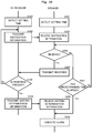
- Fig. 10 is a flow chart showing control of the information processing method according to the fourth modification example of the present invention.
- the configuration is different from the configuration of the information processing system 100 in that the speaker 2 has a not-shown RTC.
- the CPU 10 detects a setting time on the basis of the acquired event information (S101) .
- the MCU 24 detects the setting time on the basis of the acquired event information (S201).
- the CPU 10 transmits instruction information to the speaker 2 (S102).
- the speaker 2 when receiving the instruction information (S202), transmits a response indicating the reception of the setting information, to the AV receiver 1 (S203).
- the CPU 10 retransmits the instruction information to the speaker 2 (S102).
- the CPU 10 repeats to transmit the instruction information until the reception of a response from the speaker 2, or the predetermined number of times or for a predetermined time.
- the speaker 2 does not receive the instruction information (S204: No) after the MCU 24 detects the setting time, and then a predetermined time elapses (S207: Yes) after the MCU 24 detects the setting time, the speaker 2, without receiving the setting determination information, executes an alarm (S206).
- the MCU 24 again determines whether or not the MCU 24 receives instruction information (S204).
- a stop command when a user operates the stop button 251, a pause command when a user operates the pause button 252, and a volume control command when a user operates the volume control button 253 are transmitted to the reception portion 143 of the AV receiver 1, the association between the button of the speaker 2 and a command is not limited to this example.
- a power button may be associated with a stop command, and a button other than the power button may be associated with a pause command or a volume control command.
Landscapes
- Engineering & Computer Science (AREA)
- Physics & Mathematics (AREA)
- General Physics & Mathematics (AREA)
- General Health & Medical Sciences (AREA)
- Theoretical Computer Science (AREA)
- Health & Medical Sciences (AREA)
- Acoustics & Sound (AREA)
- Otolaryngology (AREA)
- Electromagnetism (AREA)
- Signal Processing (AREA)
- Multimedia (AREA)
- Audiology, Speech & Language Pathology (AREA)
- Human Computer Interaction (AREA)
- General Engineering & Computer Science (AREA)
- Computer Networks & Wireless Communication (AREA)
- Circuit For Audible Band Transducer (AREA)
- Selective Calling Equipment (AREA)
Abstract
Description
- A preferred embodiment of the present invention relates to an information processing apparatus, an information processing system, and an information processing method that are related to an alarm function.
- Conventionally, a network audio system in which, by transmitting an audio signal by wireless, the audio signal is received by an audio playback device to play a sound has been proposed (see Japanese Unexamined Patent Application Publication No.
2013-232929 PCT Application) No. 2014-516450 2013-232929 PCT Application) No. 2014-516450 - In the network audio system of Japanese Unexamined Patent Application Publication No.
2013-232929 PCT Application) No. 2014-516450 - In view of the foregoing, an object of a preferred embodiment of the present invention is to provide an information processing apparatus, an information processing system, and an information processing method that are able to achieve an alarm function even when a device that does not seem to have an alarm function is used as a playback device.
- An information processing apparatus according to a preferred embodiment of the present invention includes an acquisition portion that acquires event information as a trigger; and a transmission portion that transmits first instruction information that causes a predetermined sound to be played or play data that causes a predetermined sound to be played, to a playback device, at timing on a basis of the event information acquired by the acquisition portion.
- According to a preferred embodiment of the present invention, even in a device in which a playback device does not seem to have an alarm function, a predetermined sound is able to be played at timing on the basis of an instruction of a user.
- The above and other elements, features, characteristics, and advantages of the present invention will become more apparent from the following detailed description of the preferred embodiments with reference to the attached drawings.
-
-
Fig. 1 is a block diagram illustrating a hardware configuration of an information processing system according to a first preferred embodiment of the present invention. -
Fig. 2 is a flow chart showing control performed by the information processing system according to the first preferred embodiment of the present invention. -
Fig. 3 is a flow chart showing control performed by the information processing system according to the first preferred embodiment of the present invention. -
Fig. 4 is a flow chart showing control performed by the information processing system according to the first preferred embodiment of the present invention. -
Fig. 5 is a flow chart showing control performed by the information processing system according to the first preferred embodiment of the present invention. -
Fig. 6 is a conceptual view illustrating an information processing system according to a third preferred embodiment of the present invention. -
Fig. 7 is a flow chart showing control of an information processing method according to a first modification example of the present invention. -
Fig. 8 is a flow chart showing control of an information processing method according to a second modification example of the present invention. -
Fig. 9 is a flow chart showing control of an information processing method according to a third modification example of the present invention. -
Fig. 10 is a flow chart showing control of an information processing method according to a fourth modification example of the present invention. -
Fig. 1 is a block diagram illustrating a hardware configuration of aninformation processing system 100 according to a first preferred embodiment of the present invention. It is to be noted that the configuration of the information processing system illustrated below is merely an example, is not limited to this configuration, and is able to be appropriately changed according to specifications. - As illustrated in
Fig. 1 , theinformation processing system 100 is provided with anAV receiver 1 and aspeaker 2. TheAV receiver 1 corresponds to the information processing apparatus of the present invention, and thespeaker 2 corresponds to the playback device of the present invention. It is to be noted that the information processing apparatus is able to be implemented by not only the AV receiver but also a speaker provided with a CPU and a DSP, for example, a personal computer, or the like. In addition, the playback device is able to be implemented by not only a speaker but also anything that is able to play a sound. - The
speaker 2 is provided with anetwork module 20, a D/A converter 21, anamplifier 22, aspeaker unit 23, an MCU (Micro Controller Unit) 24, and akey 25. - The MCU 24 reads a program and the like that are stored in a memory inside the
MCU 24, and executes various control processing. Thenetwork module 20 is an interface that performs transmission and reception of data with theAV receiver 1. As a result, thespeaker 2 is able to perform the transmission and reception of data with theAV receiver 1 through thenetwork module 20. The MCU 24 decodes audio data transmitted from thenetwork module 20, and outputs a digital signal. The D/A converter 21 converts the digital signal into an analog signal. Theamplifier 22 inputs the analog signal converted by the D/A converter 21. In addition, theMCU 24 is also able to read the audio data (audio data of a beep sound, for example) stored in a not-shown flash memory and input a digital signal of the beep sound into the D/A converter 21. It is to be noted that, in a case in which thespeaker 2 is provided with the DSP, theMCU 24 is also able to instruct the DSP provided in thespeaker 2, generate a digital signal of an alarm sound, and input the digital signal into the D/A converter 21. Theamplifier 22 amplifies a supplied analog signal and outputs an amplified signal to thespeaker unit 23. Thespeaker unit 23 emits a sound according to a signal supplied from theamplifier 22. - The
key 25 is an operation portion provided in thespeaker 2, and, for example, includes astop button 251, apause button 252, avolume control button 253, and the like. It is to be noted that thekey 25 is not limited to thestop button 251, thepause button 252, and thevolume control button 253, but also includes the operation portion provided in thespeaker 2. When a user operates any of the operation portion of thekey 25, operation information corresponding to an operated operation portion is transmitted to theMCU 24. The MCU 24 transmits the operation information acquired through thenetwork module 20 to theAV receiver 1. - The
AV receiver 1 is provided with aCPU 10, aROM 11, aRAM 12 and a DSP (Digital Signal Processor) 14, anetwork module 15, and an RTC (Real Time Clock) 16 that are connected through abus 18. TheROM 11 stores asound source 111. - The
CPU 10 controls each portion of theAV receiver 1. TheROM 11 is a flash memory, for example, and stores various programs for theDSP 14, data for theDSP 14, a firmware program that manages the basic operations of theAV receiver 1, various control programs, and the like. TheCPU 10 reads a program and the like that are stored in theROM 11, and executes various control processing. TheRAM 12 stores various data temporarily and functions as a working area. It is to be noted that various control programs may be recorded in other recording media (an optical disk, a magnetic disk, or the like) that can be read by theAV receiver 1. - In the
AV receiver 1, theROM 11 is able to store the audio data acquired from an external device. TheDSP 14, under the control of theCPU 10, reads a program or data for the DSP stored in theROM 11, and performs various processing such as adding an effect to the audio data read from theROM 11. In addition, theCPU 10 is able to control theDSP 14 to generate an audio digital signal. TheCPU 10 outputs the audio signal to which effect addition, signal generation, or the like is performed by theDSP 14, to thenetwork module 15. - The
network module 15 is an interface that transmits and receives data to and from an external device such as aspeaker 2. For example, the transmission and reception of data is able to be performed between devices such as various external drive devices, an audio device, or a personal computer through thenetwork module 15. In addition, theAV receiver 1 is able to perform the transmission and reception of data between devices connected to a communication network such as a LAN (Local Area Network) through thenetwork module 15. It is to be noted that the network may be constructed by either wired or wireless connections. - The
ROM 11 stores asound source 111. Thesound source 111 is what is called audio data, and includes, for example, various types of sounds such as music, a conversation sound, an alarm sound, a noise sound, or a beep sound. - The
RTC 16 has a clock function. TheRTC 16 transmits time information to theCPU 10. As a result, theCPU 10 is able to acquire time information at any time. - The
CPU 10 issues various instructions based on the information that has been input through thenetwork module 15 and the time information that has been transmitted from theRTC 16. In the present preferred embodiment, the information that theAV receiver 1 transmits is instruction information for causing thespeaker 2 to play a predetermined sound. TheCPU 10 is provided with anacquisition portion 141, atransmission portion 142, and areception portion 143. - The
acquisition portion 141 acquires event information as a trigger. A user inputs the event information from the outside to theAV receiver 1 through thenetwork module 15. For example, the user inputs the event information by using application software installed in a not-shown smartphone or a personal computer that is able to communicate with theAV receiver 1. Theacquisition portion 141 acquires the event information that has been input by the user, through thenetwork module 15. The event information includes, for example, not only date and time and a start time to cause thespeaker 2 to play a predetermined sound but also information such as an event, the weather, or a temperature. - The
transmission portion 142 transmits a play instruction (first instruction information) that causes a predetermined sound to be played at timing on the basis of the event information acquired by theacquisition portion 141, to thespeaker 2. The play instruction is an example of the first instruction information of the present invention. TheCPU 10, when receiving event information, checks timing (T1) on the basis of the event information against current time information that is able to be acquired at any time from theRTC 16. The timing (T1) is time information such as date and time when an alarm is generated by thespeaker 2. When the current time reaches a time of the timing (T1), thetransmission portion 142 of theCPU 10 transmits a play instruction to thespeaker 2. TheMCU 24, when receiving the play instruction transmitted from theAV receiver 1, plays a predetermined sound (a beep sound, for example) . As a result, thespeaker 2 plays a predetermined sound at timing on the basis of event information. Therefore, even when thespeaker 2 does not have an alarm function, the alarm function is able to be achieved in thespeaker 2. - In the present preferred embodiment, a predetermined sound may be a sound originally stored in the
speaker 2. In such a case, thespeaker 2 plays a sound stored in an own device. Alternatively, thespeaker 2 is able to play sound information transmitted from thesound source 111 of theAV receiver 1. In such a case, theCPU 10 selects audio data of a type on the basis of the event information acquired by theacquisition portion 141, from thesound source 111. Thetransmission portion 142 transmits selected audio data to thespeaker 2. In a case in which the sound information transmitted from thesound source 111 of theAV receiver 1 is played, a sound that is not stored in thespeaker 2 is able to be played. For example, even in a case in which the sound stored in thespeaker 2 is only a beep sound, the music transmitted from thesound source 111 of theAV receiver 1 is able to be played. In addition, even in a case in which no sound is stored in thespeaker 2, the alarm function is able to be achieved by playing the sound information transmitted from thesound source 111 of theAV receiver 1. - The
reception portion 143 receives a predetermined command from thespeaker 2. The predetermined command is transmitted from thespeaker 2 to theAV receiver 1, for example, when a user operates the operation portion of either of thekeys 25 of thespeaker 2. Thereception portion 143 of theAV receiver 1 receives the predetermined command corresponding to the operation portion transmitted from thespeaker 2. - In the present preferred embodiment, in a case in which a user operates the
stop button 251 of thespeaker 2, a stop command is transmitted to thereception portion 143 of theAV receiver 1. TheCPU 10 transmits a stop instruction (second instruction information) to thespeaker 2 in response to the stop command. The stop instruction is an example of the second instruction information of the present invention. Thetransmission portion 142 transmits the stop instruction to thespeaker 2. TheMCU 24, when receiving the stop instruction transmitted from theAV receiver 1, stops a predetermined sound being played. - In addition, in a case in which a user operates the
pause button 252 of thespeaker 2, a pause command is transmitted to thereception portion 143 of theAV receiver 1. TheCPU 10, in response to the pause command, transmits a pause instruction and then retransmits a play instruction (third instruction information) after a lapse of a certain time. The instruction to transmit a pause instruction and then play again after a lapse of a certain time is an example of the third instruction information on the present invention. In other words, when theCPU 10 receives the pause command, thetransmission portion 142 transmits a pause instruction to thespeaker 2, and records a stop time (T2) in theRAM 12. TheMCU 24, when receiving the pause instruction transmitted from theAV receiver 1, stops a predetermined sound being played. TheCPU 10 calculates timing (T3) in which a certain time elapses from the timing (T2) in which thespeaker 2 has stopped playing. TheCPU 10 checks the timing (T3) in which a certain time elapses from the timing (T2) in which thespeaker 2 has stopped playing against current time information that is able to be acquired at any time from theRTC 16. When the current time reaches the timing (T3) in which a certain time elapses from the timing (T2) in which thespeaker 2 has stopped playing, thetransmission portion 142 of theCPU 10 retransmits a play instruction to thespeaker 2. Thespeaker 2, when receiving the play instruction, stops a predetermined sound being played and plays a predetermined sound again after a lapse of a certain time. As a result, theinformation processing system 100 is able to achieve what is called a snooze function. It is to be noted that the sound that thespeaker 2 plays again is not limited to the predetermined sound that has been played the first time and may be sound other than the predetermined sound. - In addition, in a case in which a user operates the
volume control button 253 of thespeaker 2, a volume control command is transmitted to thereception portion 143 of theAV receiver 1. TheCPU 10 transmits a volume control instruction (fourth instruction information) to thespeaker 2 in response to the volume control command. The volume control instruction is an example of the fourth instruction information of the present invention to change the volume of a predetermined sound. Thetransmission portion 142 that has received the instruction transmits the volume control instruction to thespeaker 2. TheMCU 24, when receiving the volume control instruction transmitted from theAV receiver 1, transmits the volume control instruction to theamplifier 22. Theamplifier 22 amplifies a supplied analog signal in accordance with the volume control instruction from theMCU 24 and outputs an amplified signal to thespeaker unit 23. Thespeaker unit 23 emits a sound according to a signal supplied from theamplifier 22. As a result, thespeaker 2 is able to emit a sound of which the volume has been controlled based on the volume control instruction. For example, in a case in which a user operates thevolume control button 253 of thespeaker 2 so as to increase a volume, thespeaker 2 plays a predetermined sound so as to increase the volume of the predetermined sound. In addition, in a case in which a user operates thevolume control button 253 of thespeaker 2 so as to decrease a volume, thespeaker 2 plays a predetermined sound so as to decrease the volume of the predetermined sound. As a result, theinformation processing system 100 is able to change the playing of a predetermined sound. It is to be noted that examples of change of a predetermined sound include intermittent playing or the change of playing speed, other than the change of the strength of a playing sound. -
Fig. 2 ,Fig. 3 ,Fig. 4 , andFig. 5 are flow charts showing control performed by theinformation processing system 100. Hereinafter, a description will be given of an information processing method in theinformation processing system 100. - As illustrated in
Fig. 2 , first, theacquisition portion 141 acquires event information as a trigger (S11). Next, theCPU 10 checks timing (T1) on the basis of acquired event information against current time information that is able to be acquired at any time from theRTC 16. When the current time reaches the timing (T1) (S12: Yes), thetransmission portion 142 transmits a play instruction that causes a predetermined sound to be played, to the speaker 2 (S13) . Thespeaker 2, when receiving the play instruction (S21), plays a predetermined sound (S22). In a case in which the current time has not reached the timing (T1) (S12: No), thetransmission portion 142 does not transmit the play instruction. Therefore, even when thespeaker 2 does not seem to have an alarm function, since thespeaker 2 is able to play a predetermined sound if the current time reaches the timing (T1), the alarm function is able to be achieved in thespeaker 2. - As illustrated in
Fig. 3 , when a user operates the key 25 of thespeaker 2, a predetermined command is input (S23). Thereception portion 143 of theAV receiver 1 receives the predetermined command from the speaker 2 (S14). Subsequently, theCPU 10 determines whether or not an input command is a stop command (S15). In a case in which the predetermined command is a stop command that indicates playing stop (S15: Yes), thetransmission portion 142 of theAV receiver 1 transmits a stop instruction (second instruction information) to the speaker 2 (S16). Thespeaker 2 receives the stop instruction (S24), and thespeaker 2 stops the playing of a predetermined sound being played (S25) . In a case in which the predetermined command is not the second instruction information that indicates playing stop (S15: No), theCPU 10 shifts the current operation to a predetermined operation illustrated inFig. 4 . - As illustrated in
Fig. 4 , in a case in which the predetermined command is a pause command (S17: Yes), theCPU 10 records a pause time (T2) in theRAM 12 in response to the pause command, and thetransmission portion 142 transmits a stop instruction to the speaker 2 (S18) . Thespeaker 2 receives the stop instruction (S26), and thespeaker 2 stops the playing of the predetermined sound being played (S27) . In a case in which the predetermined command is not the pause command (S17 : No), theCPU 10 shifts the current operation to a predetermined operation illustrated inFig. 5 . TheCPU 10 checks the timing (T3) in which a certain time elapses from the timing (T2) in which thespeaker 2 has stopped playing against current time information that is able to be acquired at any time from theRTC 16. When the current time reaches the timing (T3) (S19: Yes), thetransmission portion 142 of theAV receiver 1 retransmits a play instruction to the speaker 2 (S20) . Thespeaker 2 receives the third instruction information (S28), and thespeaker 2 plays a predetermined sound (S29) . In a case in which the current time has not reached the timing (T3) (S19: No), thetransmission portion 142 does not transmit the play instruction. As a result, what is called a snooze function is able to be achieved. - As illustrated in
Fig. 5 , in a case in which a predetermined command is a sound change command (turn up the volume, for example) that indicates an instruction that changes a predetermined sound (S41: Yes), thetransmission portion 142 of theAV receiver 1 transmits a volume control instruction (turn up the volume) to the speaker 2 (S42). Thespeaker 2 receives the volume control instruction (turn up the volume) (S30), and changes (turn up the volume) the predetermined sound being played (S31) . In a case in which the predetermined command is not a sound change command (S41: No), thetransmission portion 142 does not transmit an instruction to change a sound, to thespeaker 2. Therefore, thespeaker 2 keeps playing without changing the predetermined sound. As a result, the input of a command from thespeaker 2 is able to change the playing of a predetermined sound of thespeaker 2. - Hereinafter, a description is given of an information processing system 200 according to a second preferred embodiment of present invention. The information processing system 200 according to the second preferred embodiment has the same configuration as an
information processing system 100 according to the first preferred embodiment except that play data in addition to various instruction information is transmitted from theAV receiver 1 to thespeaker 2. Therefore, the description of a configuration similar to the configuration of theinformation processing system 100 is omitted. In addition, theinformation processing system 100 according to the first preferred embodiment is referred to for a description of the information processing system 200 according to the second preferred embodiment. - In the information processing system 200 according to the second preferred embodiment, the
acquisition portion 141 acquires the event information that has been transmitted by a user, through thenetwork module 15. TheCPU 10 selects data from thesound source 111 based on the event information acquired by theacquisition portion 141, and defines the data as play data. Thetransmission portion 142 transmits a play instruction (first instruction information) that causes a predetermined sound to be played at timing on the basis of the event information acquired by theacquisition portion 141, and the play data, to thespeaker 2. As a result, thespeaker 2 plays the predetermined sound on the basis of the play data at timing on the basis of the event information. Therefore, even when thespeaker 2 does not seem to have an alarm function, the alarm function is able to be achieved in thespeaker 2. - In the present preferred embodiment, the
CPU 10, when selecting the play data from thesound source 111, is able to simultaneously select a plurality of types of sounds from thesound source 111 as a predetermined sound. TheCPU 10 is able to select, for example, an alarm sound that indicates that the current time reaches a predetermined time and music that indicates the weather of the day as play data from thesound source 111. Thetransmission portion 142 transmits selected play data to thespeaker 2. As a result, thespeaker 2 is able to play a plurality of types of sounds stored in thesound source 111 without reading the audio data stored in the memory of theMCU 24 of thespeaker 2. - The
reception portion 143 of theAV receiver 1 receives a predetermined command. For example, in the case in which a user operates thestop button 251 of thespeaker 2, a playing stop command is transmitted to thereception portion 143 of theAV receiver 1. When theCPU 10 receives the playing stop command, thetransmission portion 142 transmits a stop instruction to thespeaker 2. At the same time, thetransmission portion 142 stops the transmission of the play data to thespeaker 2. As a result, the play data is not transmitted from theAV receiver 1 to thespeaker 2, and theMCU 24, when receiving the stop instruction transmitted from theAV receiver 1, stops a predetermined sound being played. - In the case in which a user operates the
pause button 252 of thespeaker 2, thespeaker 2 transmits a pause command to thereception portion 143 of theAV receiver 1. When theCPU 10 receives the pause command, thetransmission portion 142 transmits a stop instruction to thespeaker 2. At the same time, thetransmission portion 142 stops the transmission of the play data to thespeaker 2. When the timing (T2) in which thespeaker 2 has stopped playing reaches the timing (T3) in which a certain time elapses, thetransmission portion 142 retransmits a play instruction to thespeaker 2. At the same time, thetransmission portion 142 transmits the play data to thespeaker 2. As a result, the play data is retransmitted from theAV receiver 1 to thespeaker 2, and thespeaker 2 is able to play a predetermined sound at the timing (T3) . In other words, what is called a snooze function is able to be achieved in thespeaker 2. -
Fig. 6 is a conceptual view illustrating aninformation processing system 300 according to a third preferred embodiment of the present invention. Theinformation processing system 300 has the same configuration as theinformation processing system 100 or the information processing system 200 except that a plurality of speakers are included. Therefore, the description of a configuration similar to the configuration of theinformation processing system 100 or the information processing system 200 is omitted. - As illustrated in
Fig. 6 , theinformation processing system 300 is provided with theAV receiver 1 and a plurality ofspeakers AV receiver 1 is connected to each of the plurality ofspeakers 41 to 45 through a communication network such as the Internet or the LAN (Local Area Network) and is able to mutually perform the transmission and reception of data. It is to be noted that the network may be constructed by either wired or wireless connections. - The
AV receiver 1 transmits the first instruction information or play data that causes a predetermined sound of a different type to be played, to each of the plurality ofspeakers 41 to 45. For example, thespeakers 41 to 45 may be arranged in different rooms, respectively, and may be used by different users. In a case in which a user of each of thespeakers 41 to 45 uses thespeakers 41 to 45 as an alarm, the user individually inputs required event information to theAV receiver 1. As a result, theAV receiver 1 is able to play a predetermined sound on the basis of the event information that the user has input, in each of thespeakers 41 to 45. Therefore, each of thespeakers 41 to 45 is able to emit a different sound at a different time. - In addition, when a user operates the key 25 for each of the
speakers 41 to 45, thespeakers 41 to 45 individually transmit a predetermined command to thereception portion 143 of theAV receiver 1. As a result, each of thespeakers 41 to 45 is able to be operated. - It is to be noted that, while the present preferred embodiment exemplifies the information processing method of the
information processing system 100 in a case in which communication between theAV receiver 1 and thespeaker 2 is normal, the following first modification example, second modification example, third modification example, and fourth modification example enable theinformation processing system 100 to be adapted also to the case in which the communication between theAV receiver 1 and thespeaker 2 is not normal. Hereinafter, a description is given of the first to fourth modification examples. It is to be noted that the description of a configuration similar to the configuration of the information processing method of theinformation processing system 100 is omitted. -
Fig. 7 is a flow chart showing control of the information processing method according to the first modification example of the present invention. As illustrated inFig. 7 , in the first modification example, theCPU 10 transmits instruction information on the basis of acquired event information to the speaker 2 (S71). Thespeaker 2, when receiving the instruction information (S72), transmits a response indicating the reception of the instruction information, to the AV receiver 1 (S73). In the present preferred embodiment, in a case in which the communication between theAV receiver 1 and thespeaker 2 is not normal, theAV receiver 1 is not able to obtain the response from thespeaker 2. Subsequently, theCPU 10 determines whether or not a response from thespeaker 2 is present (S74). In a case in which a response from thespeaker 2 is present (S74: Yes), theCPU 10 transmits instruction determination information to the speaker 2 (S75). Thespeaker 2, when receiving the instruction determination information (S76), executes a predetermined operation according to instruction information (S77). For example, in a case in which the instruction information indicates play of a predetermined sound, thespeaker 2 plays the predetermined sound, which achieves an alarm function. In a case in which a response from thespeaker 2 is absent (S74: No), theCPU 10 transmits setting information to thespeaker 2 again (S71). In this manner, in the case in which the communication between theAV receiver 1 and thespeaker 2 is not normal, theCPU 10 repeats to transmit setting information until reception of a response from thespeaker 2, or the predetermined number of times or for a predetermined time. As a result, even in a case in which an abnormality occurs in the communication between theAV receiver 1 and thespeaker 2 temporarily, an alarm or the like is able to be set to thespeaker 2. -
Fig. 8 is a flow chart showing control of the information processing method according to the second modification example of the present invention. As illustrated inFig. 8 , in the second modification example, when a user operates the key 25 of thespeaker 2, a predetermined command is input (S23). Subsequently, thespeaker 2 transmits the input command information to the AV receiver 1 (S81), and changes an operation that thespeaker 2 is performing temporarily (S83). For example, thespeaker 2 stops playing a predetermined sound being played. TheAV receiver 1, when receiving command information (S82), transmits a response indicating the reception of the command information, to the speaker 2 (S84). TheMCU 24 determines whether or not a response from theAV receiver 1 is present (S85). In a case in which a response from theAV receiver 1 is present (S85: Yes), theMCU 24 executes a command according to the command information (S86). In other words, in a case in which a predetermined command is a stop command that indicates playing stop, thespeaker 2 stops playing a predetermined sound being played. As a result, even when a different command is being executed temporarily, a current process is changed to a process on the basis of the command information, and the command is executed. In a case in which a response from theAV receiver 1 is absent (S85: No), theMCU 24 retransmits the command information to the AV receiver 1 (S81). In this manner, in the case in which the communication between theAV receiver 1 and thespeaker 2 is not normal, theMCU 24 repeats to transmit setting information until reception of a response from theAV receiver 1, or the predetermined number of times or for a predetermined time. As a result, even in the case in which an abnormality occurs in the communication between theAV receiver 1 and thespeaker 2 temporarily, a predetermined command is able to be executed to thespeaker 2. -
Fig. 9 is a flow chart showing control of the information processing method according to the third modification example of the present invention. In the third modification example, the configuration is different from the configuration of theinformation processing system 100 in that thespeaker 2 has a not-shown RTC. As illustrated inFig. 9 , theacquisition portion 141 acquires event information as a trigger (S11). Subsequently, theCPU 10 transmits setting information on the basis of acquired event information to the speaker 2 (S91). Thespeaker 2, when receiving the setting information (S92), transmits a response indicating the reception of the setting information, to the AV receiver 1 (S93). In the present preferred embodiment, in a case in which the communication between theAV receiver 1 and thespeaker 2 is not normal, theAV receiver 1 is not able to obtain the response from thespeaker 2. Subsequently, theCPU 10 determines whether or not a response from thespeaker 2 is present (S94). In a case in which a response from thespeaker 2 is present (S94: Yes), theCPU 10 transmits setting determination information to the speaker 2 (S95). Thespeaker 2, when receiving the setting determination information (S96), determines the setting of an alarm (S97). Since thespeaker 2 has the not-shown RTC, an alarm is set based on the RTC of thespeaker 2, and the setting of the alarm is recorded in the memory of theMCU 24. When time of the RTC of thespeaker 2 reaches a set time, theMCU 24 causes a predetermined sound to be played, which achieves an alarm function. In a case in which a response from thespeaker 2 is absent (S94: No), theCPU 10 retransmits setting information to the speaker 2 (S91). In this manner, in the case in which the communication between theAV receiver 1 and thespeaker 2 is not normal, theCPU 10 repeats to transmit setting information until reception of a response from thespeaker 2, or the predetermined number of times or for a predetermined time. As a result, even in the case in which an abnormality occurs in the communication between theAV receiver 1 and thespeaker 2 from a setup time to an alarm scheduled time, an alarm or the like is able to be set to thespeaker 2. -
Fig. 10 is a flow chart showing control of the information processing method according to the fourth modification example of the present invention. In the fourth modification example, the configuration is different from the configuration of theinformation processing system 100 in that thespeaker 2 has a not-shown RTC. As illustrated inFig. 10 , theCPU 10 detects a setting time on the basis of the acquired event information (S101) . Similarly, theMCU 24 detects the setting time on the basis of the acquired event information (S201). When theCPU 10 detects the setting time, theCPU 10 transmits instruction information to the speaker 2 (S102). Thespeaker 2, when receiving the instruction information (S202), transmits a response indicating the reception of the setting information, to the AV receiver 1 (S203). In a case in which a response from thespeaker 2 is present (S103: Yes), in other words, in a case in which thespeaker 2 receives the instruction information within a predetermined time after theMCU 24 detects the setting time (S204 : Yes), theCPU 10 transmits setting determination information to the speaker 2 (S104). Thespeaker 2, when receiving the setting determination information (S205), plays a predetermined sound and executes an alarm (S206). - In addition, in a case in which a response from the
speaker 2 is absent (S103: No), theCPU 10 retransmits the instruction information to the speaker 2 (S102). In this manner, in the case in which the communication between theAV receiver 1 and thespeaker 2 is not normal, theCPU 10 repeats to transmit the instruction information until the reception of a response from thespeaker 2, or the predetermined number of times or for a predetermined time. As a result, even in the case in which an abnormality occurs in the communication between theAV receiver 1 and thespeaker 2 after theAV receiver 1 detects the setting time, an alarm or the like is able to be achieved in thespeaker 2. - Further, in a case in which the
speaker 2 does not receive the instruction information (S204: No) after theMCU 24 detects the setting time, and then a predetermined time elapses (S207: Yes) after theMCU 24 detects the setting time, thespeaker 2, without receiving the setting determination information, executes an alarm (S206). In a case in which time does not reach a predetermined time (S207: No) after theMCU 24 detects the setting time, theMCU 24 again determines whether or not theMCU 24 receives instruction information (S204). As a result, even in the case in which an abnormality occurs in the communication between theAV receiver 1 and thespeaker 2 after thespeaker 2 detects the setting time, an alarm or the like is able to be achieved in thespeaker 2. - It is to be noted that, while, in the present preferred embodiment, a stop command when a user operates the
stop button 251, a pause command when a user operates thepause button 252, and a volume control command when a user operates thevolume control button 253 are transmitted to thereception portion 143 of theAV receiver 1, the association between the button of thespeaker 2 and a command is not limited to this example. For example, a power button may be associated with a stop command, and a button other than the power button may be associated with a pause command or a volume control command. - While preferred embodiments of the present invention have been described above, it is to be understood that variations and modifications will be apparent to those skilled in the art without departing from the scope and spirit of the present invention. The scope of the present invention, therefore, is to be determined solely by the following claims.
Claims (11)
- An information processing apparatus comprising:an acquisition portion (141) that acquires event information as a trigger; anda transmission portion (142) that transmits first instruction information that causes a predetermined sound to be played or play data that causes a predetermined sound to be played, to a playback device (2), at timing on a basis of the event information acquired by the acquisition portion (141).
- The information processing apparatus according to claim 1, further comprising a reception portion (143) that receives a predetermined command from the playback device (2), wherein the transmission portion (142), when the reception portion (143) receives the predetermined command from the playback device (2), transmits second instruction information that causes playing of the predetermined sound to be stopped, to the playback device (2).
- The information processing apparatus according to claim 2, wherein the transmission portion (142) retransmits third instruction information that causes the predetermined sound or other predetermined sounds to be played after a lapse of a certain time from stop of the playing of the predetermined sound, to the playback device (2).
- The information processing apparatus according to any one of claims 1 to 3, wherein the transmission portion (142) transmits fourth instruction information that changes the predetermined sound, to the playback device (2).
- The information processing apparatus according to any one of claims 1 to 4, further comprising a reception portion (143) that receives a predetermined command from the playback device (2), wherein the transmission portion (142), when the reception portion (143) receives the predetermined command from the playback device (2), stops transmission of the play data.
- The information processing apparatus according to claim 5, wherein the transmission portion (142) retransmits the play data or other play data to the playback device (2) after a lapse of a certain time from stop of the transmission of the play data.
- The information processing apparatus according to any one of claims 1 to 6, wherein the predetermined sound includes a sound of a plurality of types of sound sources.
- The information processing apparatus according to any one of claims 1 to 7, wherein the transmission portion (142), when a plurality of playback devices (2) are present, transmits first instruction information that causes each playback device (2) to play the predetermined sound of different types or play data, to each of the playback devices (2).
- An information processing system comprising:the information processing device according to any one of claims 1 to 8; anda playback device (2).
- An information processing method comprising:acquiring event information as a trigger; andtransmitting first instruction information that causes a predetermined sound to be played or play data that causes a predetermined sound to be played, to a playback device (2), at timing on a basis of the event information that has been acquired.
- The information processing method according to claim 10, further comprising:receiving a predetermined command from the playback device (2), andtransmitting, when the predetermined command is received from the playback device (2), second instruction information that causes playing of the predetermined sound to be stopped, to the playback device (2).
Applications Claiming Priority (1)
| Application Number | Priority Date | Filing Date | Title |
|---|---|---|---|
| JP2017058379A JP2018160871A (en) | 2017-03-24 | 2017-03-24 | Information processing apparatus, information processing system, and information processing method |
Publications (2)
| Publication Number | Publication Date |
|---|---|
| EP3382474A1 true EP3382474A1 (en) | 2018-10-03 |
| EP3382474B1 EP3382474B1 (en) | 2022-01-26 |
Family
ID=61599046
Family Applications (1)
| Application Number | Title | Priority Date | Filing Date |
|---|---|---|---|
| EP18160685.6A Active EP3382474B1 (en) | 2017-03-24 | 2018-03-08 | Information processing apparatus, information processing system, and information processing method |
Country Status (3)
| Country | Link |
|---|---|
| US (1) | US10489107B2 (en) |
| EP (1) | EP3382474B1 (en) |
| JP (1) | JP2018160871A (en) |
Citations (5)
| Publication number | Priority date | Publication date | Assignee | Title |
|---|---|---|---|---|
| US5555536A (en) * | 1994-07-19 | 1996-09-10 | Rolf; Rebecca L. | Device for playing recorded audio at a selected time |
| US20080089184A1 (en) * | 2006-10-12 | 2008-04-17 | Palmer Robin B | Motivational alarm |
| JP2013232929A (en) | 2013-06-12 | 2013-11-14 | Yamaha Corp | Radio audio system |
| JP2014516450A (en) | 2011-04-18 | 2014-07-10 | ソノズ インコーポレイテッド | Audio smart line input processing |
| WO2017007596A1 (en) * | 2015-07-08 | 2017-01-12 | Google Inc. | Wake up to a cast alarm or an alarm plus content prompt |
Family Cites Families (23)
| Publication number | Priority date | Publication date | Assignee | Title |
|---|---|---|---|---|
| JPH0632508B2 (en) * | 1984-03-29 | 1994-04-27 | ソニー株式会社 | Remote control device |
| JPH11250637A (en) * | 1998-03-02 | 1999-09-17 | Sony Corp | Portable electronic device with remote control |
| US6816703B1 (en) * | 1999-11-30 | 2004-11-09 | Leapfrog Enterprises, Inc. | Interactive communications appliance |
| AU2001253161A1 (en) * | 2000-04-04 | 2001-10-15 | Stick Networks, Inc. | Method and apparatus for scheduling presentation of digital content on a personal communication device |
| US7142934B2 (en) * | 2000-09-01 | 2006-11-28 | Universal Electronics Inc. | Audio converter device and method for using the same |
| JP2002099488A (en) * | 2000-09-25 | 2002-04-05 | Kyubunkan:Kk | Information distributing device, terminal device, information distributing method and record medium |
| US20020082730A1 (en) * | 2000-12-21 | 2002-06-27 | Microsoft Corporation | Universal media player |
| JP2002208265A (en) * | 2001-01-09 | 2002-07-26 | Kenwood Corp | Recording and reproducing device, method of controlling recording and reproducing device and recording medium |
| US20030142591A1 (en) * | 2002-01-31 | 2003-07-31 | International Business Machines Corporation | Interactive alarm clock and method |
| US7277877B2 (en) | 2002-08-14 | 2007-10-02 | Sony Corporation | System and method for selecting a music channel |
| JP2004147163A (en) * | 2002-10-25 | 2004-05-20 | Matsushita Electric Ind Co Ltd | Security device with melody rewriting function |
| US7657223B2 (en) * | 2003-02-04 | 2010-02-02 | Nokia Siemens Networks Oy | Provision of content to mobile users |
| JP2006333051A (en) * | 2005-05-26 | 2006-12-07 | Anodeikku Supply:Kk | Voice distribution apparatus, voice distribution system, and program |
| JP4175416B2 (en) * | 2006-05-31 | 2008-11-05 | ブラザー工業株式会社 | Sound output system, electronic device, telephone device, and program |
| JP2008282348A (en) * | 2007-05-14 | 2008-11-20 | Toshiba Corp | Audio output device and audio output method |
| US9043797B2 (en) * | 2010-10-26 | 2015-05-26 | Qualcomm Incorporated | Using pause on an electronic device to manage resources |
| US8971546B2 (en) * | 2011-10-14 | 2015-03-03 | Sonos, Inc. | Systems, methods, apparatus, and articles of manufacture to control audio playback devices |
| US9225307B2 (en) | 2012-06-28 | 2015-12-29 | Sonos, Inc. | Modification of audio responsive to proximity detection |
| US9152131B2 (en) * | 2013-03-14 | 2015-10-06 | Google Technology Holdings LLC | Snooze alarm system for a wearable device |
| JP6004190B2 (en) * | 2013-09-05 | 2016-10-05 | ヤマハ株式会社 | Speaker device |
| US20150371529A1 (en) * | 2014-06-24 | 2015-12-24 | Bose Corporation | Audio Systems and Related Methods and Devices |
| US9779613B2 (en) * | 2014-07-01 | 2017-10-03 | Sonos, Inc. | Display and control of pre-determined audio content playback |
| CN104200825A (en) * | 2014-08-20 | 2014-12-10 | 英华达(上海)科技有限公司 | Wireless music playing method and system and wireless music player |
-
2017
- 2017-03-24 JP JP2017058379A patent/JP2018160871A/en active Pending
-
2018
- 2018-03-08 EP EP18160685.6A patent/EP3382474B1/en active Active
- 2018-03-16 US US15/923,468 patent/US10489107B2/en active Active
Patent Citations (5)
| Publication number | Priority date | Publication date | Assignee | Title |
|---|---|---|---|---|
| US5555536A (en) * | 1994-07-19 | 1996-09-10 | Rolf; Rebecca L. | Device for playing recorded audio at a selected time |
| US20080089184A1 (en) * | 2006-10-12 | 2008-04-17 | Palmer Robin B | Motivational alarm |
| JP2014516450A (en) | 2011-04-18 | 2014-07-10 | ソノズ インコーポレイテッド | Audio smart line input processing |
| JP2013232929A (en) | 2013-06-12 | 2013-11-14 | Yamaha Corp | Radio audio system |
| WO2017007596A1 (en) * | 2015-07-08 | 2017-01-12 | Google Inc. | Wake up to a cast alarm or an alarm plus content prompt |
Also Published As
| Publication number | Publication date |
|---|---|
| JP2018160871A (en) | 2018-10-11 |
| EP3382474B1 (en) | 2022-01-26 |
| US10489107B2 (en) | 2019-11-26 |
| US20180275953A1 (en) | 2018-09-27 |
Similar Documents
| Publication | Publication Date | Title |
|---|---|---|
| US11631403B2 (en) | Apparatus, system and method for directing voice input in a controlling device | |
| CN106104675B (en) | Activating speech processing | |
| US8582790B2 (en) | Hearing aid and computing device for providing audio labels | |
| WO2019033986A1 (en) | Sound playback device detection method, apparatus, storage medium, and terminal | |
| KR102889818B1 (en) | Device, system and method for directing voice input from a control device | |
| US9384752B2 (en) | Audio device and storage medium | |
| US20170160710A1 (en) | Voice control type bath system and operating method thereof | |
| KR101555430B1 (en) | Remote control system of domestic appliances through alarm function of smart phone, and method of the same | |
| US20220122600A1 (en) | Information processing device and information processing method | |
| EP3382474B1 (en) | Information processing apparatus, information processing system, and information processing method | |
| US12356160B2 (en) | Multi-channel audio system, multi-channel audio device, program, and multi-channel audio playback method | |
| KR100783113B1 (en) | How to save music file in mobile terminal | |
| JP6945734B2 (en) | Audio output device, device control system, audio output method, and program | |
| JP5489537B2 (en) | Sound reproduction system, sound reproduction device, and control method thereof | |
| JP2018146832A (en) | Electronic musical instrument | |
| KR102933040B1 (en) | Electorinc apparatus and control method thereof | |
| JP6921311B2 (en) | Equipment control system, equipment, equipment control method and program | |
| JP7251549B2 (en) | Information processing device, information processing method and program | |
| JP2017112567A (en) | Information providing apparatus and information providing system | |
| JP2016005233A (en) | Content playback apparatus and content playback system | |
| JP2020061046A (en) | Voice operation apparatus, voice operation method, computer program, and voice operation system | |
| CN110879695A (en) | Audio playing control method, device and storage medium | |
| JP2007329878A (en) | Remote control system | |
| KR101976091B1 (en) | Decision method for activity mode of hearing device and the auditory device | |
| JP7182154B2 (en) | Equipment control system |
Legal Events
| Date | Code | Title | Description |
|---|---|---|---|
| PUAI | Public reference made under article 153(3) epc to a published international application that has entered the european phase |
Free format text: ORIGINAL CODE: 0009012 |
|
| STAA | Information on the status of an ep patent application or granted ep patent |
Free format text: STATUS: THE APPLICATION HAS BEEN PUBLISHED |
|
| AK | Designated contracting states |
Kind code of ref document: A1 Designated state(s): AL AT BE BG CH CY CZ DE DK EE ES FI FR GB GR HR HU IE IS IT LI LT LU LV MC MK MT NL NO PL PT RO RS SE SI SK SM TR |
|
| AX | Request for extension of the european patent |
Extension state: BA ME |
|
| STAA | Information on the status of an ep patent application or granted ep patent |
Free format text: STATUS: REQUEST FOR EXAMINATION WAS MADE |
|
| 17P | Request for examination filed |
Effective date: 20190328 |
|
| RBV | Designated contracting states (corrected) |
Designated state(s): AL AT BE BG CH CY CZ DE DK EE ES FI FR GB GR HR HU IE IS IT LI LT LU LV MC MK MT NL NO PL PT RO RS SE SI SK SM TR |
|
| GRAP | Despatch of communication of intention to grant a patent |
Free format text: ORIGINAL CODE: EPIDOSNIGR1 |
|
| STAA | Information on the status of an ep patent application or granted ep patent |
Free format text: STATUS: GRANT OF PATENT IS INTENDED |
|
| INTG | Intention to grant announced |
Effective date: 20210923 |
|
| RIN1 | Information on inventor provided before grant (corrected) |
Inventor name: KANO, MASAYA |
|
| GRAS | Grant fee paid |
Free format text: ORIGINAL CODE: EPIDOSNIGR3 |
|
| GRAA | (expected) grant |
Free format text: ORIGINAL CODE: 0009210 |
|
| STAA | Information on the status of an ep patent application or granted ep patent |
Free format text: STATUS: THE PATENT HAS BEEN GRANTED |
|
| AK | Designated contracting states |
Kind code of ref document: B1 Designated state(s): AL AT BE BG CH CY CZ DE DK EE ES FI FR GB GR HR HU IE IS IT LI LT LU LV MC MK MT NL NO PL PT RO RS SE SI SK SM TR |
|
| REG | Reference to a national code |
Ref country code: GB Ref legal event code: FG4D |
|
| REG | Reference to a national code |
Ref country code: CH Ref legal event code: EP |
|
| REG | Reference to a national code |
Ref country code: AT Ref legal event code: REF Ref document number: 1465766 Country of ref document: AT Kind code of ref document: T Effective date: 20220215 |
|
| REG | Reference to a national code |
Ref country code: IE Ref legal event code: FG4D |
|
| REG | Reference to a national code |
Ref country code: DE Ref legal event code: R096 Ref document number: 602018029935 Country of ref document: DE |
|
| REG | Reference to a national code |
Ref country code: LT Ref legal event code: MG9D |
|
| REG | Reference to a national code |
Ref country code: NL Ref legal event code: MP Effective date: 20220126 |
|
| REG | Reference to a national code |
Ref country code: AT Ref legal event code: MK05 Ref document number: 1465766 Country of ref document: AT Kind code of ref document: T Effective date: 20220126 |
|
| PG25 | Lapsed in a contracting state [announced via postgrant information from national office to epo] |
Ref country code: NL Free format text: LAPSE BECAUSE OF FAILURE TO SUBMIT A TRANSLATION OF THE DESCRIPTION OR TO PAY THE FEE WITHIN THE PRESCRIBED TIME-LIMIT Effective date: 20220126 |
|
| PG25 | Lapsed in a contracting state [announced via postgrant information from national office to epo] |
Ref country code: SE Free format text: LAPSE BECAUSE OF FAILURE TO SUBMIT A TRANSLATION OF THE DESCRIPTION OR TO PAY THE FEE WITHIN THE PRESCRIBED TIME-LIMIT Effective date: 20220126 Ref country code: RS Free format text: LAPSE BECAUSE OF FAILURE TO SUBMIT A TRANSLATION OF THE DESCRIPTION OR TO PAY THE FEE WITHIN THE PRESCRIBED TIME-LIMIT Effective date: 20220126 Ref country code: PT Free format text: LAPSE BECAUSE OF FAILURE TO SUBMIT A TRANSLATION OF THE DESCRIPTION OR TO PAY THE FEE WITHIN THE PRESCRIBED TIME-LIMIT Effective date: 20220526 Ref country code: NO Free format text: LAPSE BECAUSE OF FAILURE TO SUBMIT A TRANSLATION OF THE DESCRIPTION OR TO PAY THE FEE WITHIN THE PRESCRIBED TIME-LIMIT Effective date: 20220426 Ref country code: LT Free format text: LAPSE BECAUSE OF FAILURE TO SUBMIT A TRANSLATION OF THE DESCRIPTION OR TO PAY THE FEE WITHIN THE PRESCRIBED TIME-LIMIT Effective date: 20220126 Ref country code: HR Free format text: LAPSE BECAUSE OF FAILURE TO SUBMIT A TRANSLATION OF THE DESCRIPTION OR TO PAY THE FEE WITHIN THE PRESCRIBED TIME-LIMIT Effective date: 20220126 Ref country code: ES Free format text: LAPSE BECAUSE OF FAILURE TO SUBMIT A TRANSLATION OF THE DESCRIPTION OR TO PAY THE FEE WITHIN THE PRESCRIBED TIME-LIMIT Effective date: 20220126 Ref country code: BG Free format text: LAPSE BECAUSE OF FAILURE TO SUBMIT A TRANSLATION OF THE DESCRIPTION OR TO PAY THE FEE WITHIN THE PRESCRIBED TIME-LIMIT Effective date: 20220426 |
|
| PG25 | Lapsed in a contracting state [announced via postgrant information from national office to epo] |
Ref country code: PL Free format text: LAPSE BECAUSE OF FAILURE TO SUBMIT A TRANSLATION OF THE DESCRIPTION OR TO PAY THE FEE WITHIN THE PRESCRIBED TIME-LIMIT Effective date: 20220126 Ref country code: LV Free format text: LAPSE BECAUSE OF FAILURE TO SUBMIT A TRANSLATION OF THE DESCRIPTION OR TO PAY THE FEE WITHIN THE PRESCRIBED TIME-LIMIT Effective date: 20220126 Ref country code: GR Free format text: LAPSE BECAUSE OF FAILURE TO SUBMIT A TRANSLATION OF THE DESCRIPTION OR TO PAY THE FEE WITHIN THE PRESCRIBED TIME-LIMIT Effective date: 20220427 Ref country code: FI Free format text: LAPSE BECAUSE OF FAILURE TO SUBMIT A TRANSLATION OF THE DESCRIPTION OR TO PAY THE FEE WITHIN THE PRESCRIBED TIME-LIMIT Effective date: 20220126 Ref country code: AT Free format text: LAPSE BECAUSE OF FAILURE TO SUBMIT A TRANSLATION OF THE DESCRIPTION OR TO PAY THE FEE WITHIN THE PRESCRIBED TIME-LIMIT Effective date: 20220126 |
|
| PG25 | Lapsed in a contracting state [announced via postgrant information from national office to epo] |
Ref country code: IS Free format text: LAPSE BECAUSE OF FAILURE TO SUBMIT A TRANSLATION OF THE DESCRIPTION OR TO PAY THE FEE WITHIN THE PRESCRIBED TIME-LIMIT Effective date: 20220526 |
|
| REG | Reference to a national code |
Ref country code: DE Ref legal event code: R097 Ref document number: 602018029935 Country of ref document: DE |
|
| PG25 | Lapsed in a contracting state [announced via postgrant information from national office to epo] |
Ref country code: SM Free format text: LAPSE BECAUSE OF FAILURE TO SUBMIT A TRANSLATION OF THE DESCRIPTION OR TO PAY THE FEE WITHIN THE PRESCRIBED TIME-LIMIT Effective date: 20220126 Ref country code: SK Free format text: LAPSE BECAUSE OF FAILURE TO SUBMIT A TRANSLATION OF THE DESCRIPTION OR TO PAY THE FEE WITHIN THE PRESCRIBED TIME-LIMIT Effective date: 20220126 Ref country code: RO Free format text: LAPSE BECAUSE OF FAILURE TO SUBMIT A TRANSLATION OF THE DESCRIPTION OR TO PAY THE FEE WITHIN THE PRESCRIBED TIME-LIMIT Effective date: 20220126 Ref country code: MC Free format text: LAPSE BECAUSE OF FAILURE TO SUBMIT A TRANSLATION OF THE DESCRIPTION OR TO PAY THE FEE WITHIN THE PRESCRIBED TIME-LIMIT Effective date: 20220126 Ref country code: EE Free format text: LAPSE BECAUSE OF FAILURE TO SUBMIT A TRANSLATION OF THE DESCRIPTION OR TO PAY THE FEE WITHIN THE PRESCRIBED TIME-LIMIT Effective date: 20220126 Ref country code: DK Free format text: LAPSE BECAUSE OF FAILURE TO SUBMIT A TRANSLATION OF THE DESCRIPTION OR TO PAY THE FEE WITHIN THE PRESCRIBED TIME-LIMIT Effective date: 20220126 Ref country code: CZ Free format text: LAPSE BECAUSE OF FAILURE TO SUBMIT A TRANSLATION OF THE DESCRIPTION OR TO PAY THE FEE WITHIN THE PRESCRIBED TIME-LIMIT Effective date: 20220126 |
|
| REG | Reference to a national code |
Ref country code: CH Ref legal event code: PL |
|
| PG25 | Lapsed in a contracting state [announced via postgrant information from national office to epo] |
Ref country code: AL Free format text: LAPSE BECAUSE OF FAILURE TO SUBMIT A TRANSLATION OF THE DESCRIPTION OR TO PAY THE FEE WITHIN THE PRESCRIBED TIME-LIMIT Effective date: 20220126 |
|
| PLBE | No opposition filed within time limit |
Free format text: ORIGINAL CODE: 0009261 |
|
| STAA | Information on the status of an ep patent application or granted ep patent |
Free format text: STATUS: NO OPPOSITION FILED WITHIN TIME LIMIT |
|
| REG | Reference to a national code |
Ref country code: BE Ref legal event code: MM Effective date: 20220331 |
|
| GBPC | Gb: european patent ceased through non-payment of renewal fee |
Effective date: 20220426 |
|
| 26N | No opposition filed |
Effective date: 20221027 |
|
| PG25 | Lapsed in a contracting state [announced via postgrant information from national office to epo] |
Ref country code: LU Free format text: LAPSE BECAUSE OF NON-PAYMENT OF DUE FEES Effective date: 20220308 Ref country code: LI Free format text: LAPSE BECAUSE OF NON-PAYMENT OF DUE FEES Effective date: 20220331 Ref country code: IE Free format text: LAPSE BECAUSE OF NON-PAYMENT OF DUE FEES Effective date: 20220308 Ref country code: GB Free format text: LAPSE BECAUSE OF NON-PAYMENT OF DUE FEES Effective date: 20220426 Ref country code: FR Free format text: LAPSE BECAUSE OF NON-PAYMENT OF DUE FEES Effective date: 20220326 Ref country code: CH Free format text: LAPSE BECAUSE OF NON-PAYMENT OF DUE FEES Effective date: 20220331 |
|
| PG25 | Lapsed in a contracting state [announced via postgrant information from national office to epo] |
Ref country code: SI Free format text: LAPSE BECAUSE OF FAILURE TO SUBMIT A TRANSLATION OF THE DESCRIPTION OR TO PAY THE FEE WITHIN THE PRESCRIBED TIME-LIMIT Effective date: 20220126 Ref country code: BE Free format text: LAPSE BECAUSE OF NON-PAYMENT OF DUE FEES Effective date: 20220331 |
|
| PG25 | Lapsed in a contracting state [announced via postgrant information from national office to epo] |
Ref country code: IT Free format text: LAPSE BECAUSE OF FAILURE TO SUBMIT A TRANSLATION OF THE DESCRIPTION OR TO PAY THE FEE WITHIN THE PRESCRIBED TIME-LIMIT Effective date: 20220126 |
|
| PG25 | Lapsed in a contracting state [announced via postgrant information from national office to epo] |
Ref country code: HU Free format text: LAPSE BECAUSE OF FAILURE TO SUBMIT A TRANSLATION OF THE DESCRIPTION OR TO PAY THE FEE WITHIN THE PRESCRIBED TIME-LIMIT; INVALID AB INITIO Effective date: 20180308 |
|
| PG25 | Lapsed in a contracting state [announced via postgrant information from national office to epo] |
Ref country code: MK Free format text: LAPSE BECAUSE OF FAILURE TO SUBMIT A TRANSLATION OF THE DESCRIPTION OR TO PAY THE FEE WITHIN THE PRESCRIBED TIME-LIMIT Effective date: 20220126 Ref country code: CY Free format text: LAPSE BECAUSE OF FAILURE TO SUBMIT A TRANSLATION OF THE DESCRIPTION OR TO PAY THE FEE WITHIN THE PRESCRIBED TIME-LIMIT Effective date: 20220126 |
|
| PG25 | Lapsed in a contracting state [announced via postgrant information from national office to epo] |
Ref country code: TR Free format text: LAPSE BECAUSE OF FAILURE TO SUBMIT A TRANSLATION OF THE DESCRIPTION OR TO PAY THE FEE WITHIN THE PRESCRIBED TIME-LIMIT Effective date: 20220126 |
|
| PG25 | Lapsed in a contracting state [announced via postgrant information from national office to epo] |
Ref country code: MT Free format text: LAPSE BECAUSE OF FAILURE TO SUBMIT A TRANSLATION OF THE DESCRIPTION OR TO PAY THE FEE WITHIN THE PRESCRIBED TIME-LIMIT Effective date: 20220126 |
|
| PGFP | Annual fee paid to national office [announced via postgrant information from national office to epo] |
Ref country code: DE Payment date: 20260319 Year of fee payment: 9 |