EP3382448A1 - Display apparatus - Google Patents
Display apparatus Download PDFInfo
- Publication number
- EP3382448A1 EP3382448A1 EP17163653.3A EP17163653A EP3382448A1 EP 3382448 A1 EP3382448 A1 EP 3382448A1 EP 17163653 A EP17163653 A EP 17163653A EP 3382448 A1 EP3382448 A1 EP 3382448A1
- Authority
- EP
- European Patent Office
- Prior art keywords
- light
- display apparatus
- devices
- emission area
- electro
- Prior art date
- Legal status (The legal status is an assumption and is not a legal conclusion. Google has not performed a legal analysis and makes no representation as to the accuracy of the status listed.)
- Withdrawn
Links
- 230000005540 biological transmission Effects 0.000 claims abstract description 8
- 238000000034 method Methods 0.000 claims description 21
- 230000001902 propagating effect Effects 0.000 claims description 15
- 239000004973 liquid crystal related substance Substances 0.000 claims description 14
- 230000003287 optical effect Effects 0.000 claims description 5
- 239000000463 material Substances 0.000 description 4
- 230000000694 effects Effects 0.000 description 3
- 229910021417 amorphous silicon Inorganic materials 0.000 description 1
- 238000012986 modification Methods 0.000 description 1
- 230000004048 modification Effects 0.000 description 1
- 238000004064 recycling Methods 0.000 description 1
- 230000005236 sound signal Effects 0.000 description 1
Images
Classifications
-
- G—PHYSICS
- G02—OPTICS
- G02F—OPTICAL DEVICES OR ARRANGEMENTS FOR THE CONTROL OF LIGHT BY MODIFICATION OF THE OPTICAL PROPERTIES OF THE MEDIA OF THE ELEMENTS INVOLVED THEREIN; NON-LINEAR OPTICS; FREQUENCY-CHANGING OF LIGHT; OPTICAL LOGIC ELEMENTS; OPTICAL ANALOGUE/DIGITAL CONVERTERS
- G02F1/00—Devices or arrangements for the control of the intensity, colour, phase, polarisation or direction of light arriving from an independent light source, e.g. switching, gating or modulating; Non-linear optics
- G02F1/01—Devices or arrangements for the control of the intensity, colour, phase, polarisation or direction of light arriving from an independent light source, e.g. switching, gating or modulating; Non-linear optics for the control of the intensity, phase, polarisation or colour
- G02F1/13—Devices or arrangements for the control of the intensity, colour, phase, polarisation or direction of light arriving from an independent light source, e.g. switching, gating or modulating; Non-linear optics for the control of the intensity, phase, polarisation or colour based on liquid crystals, e.g. single liquid crystal display cells
- G02F1/133—Constructional arrangements; Operation of liquid crystal cells; Circuit arrangements
- G02F1/1333—Constructional arrangements; Manufacturing methods
- G02F1/1335—Structural association of cells with optical devices, e.g. polarisers or reflectors
- G02F1/1336—Illuminating devices
- G02F1/133615—Edge-illuminating devices, i.e. illuminating from the side
-
- G—PHYSICS
- G02—OPTICS
- G02F—OPTICAL DEVICES OR ARRANGEMENTS FOR THE CONTROL OF LIGHT BY MODIFICATION OF THE OPTICAL PROPERTIES OF THE MEDIA OF THE ELEMENTS INVOLVED THEREIN; NON-LINEAR OPTICS; FREQUENCY-CHANGING OF LIGHT; OPTICAL LOGIC ELEMENTS; OPTICAL ANALOGUE/DIGITAL CONVERTERS
- G02F1/00—Devices or arrangements for the control of the intensity, colour, phase, polarisation or direction of light arriving from an independent light source, e.g. switching, gating or modulating; Non-linear optics
- G02F1/01—Devices or arrangements for the control of the intensity, colour, phase, polarisation or direction of light arriving from an independent light source, e.g. switching, gating or modulating; Non-linear optics for the control of the intensity, phase, polarisation or colour
- G02F1/13—Devices or arrangements for the control of the intensity, colour, phase, polarisation or direction of light arriving from an independent light source, e.g. switching, gating or modulating; Non-linear optics for the control of the intensity, phase, polarisation or colour based on liquid crystals, e.g. single liquid crystal display cells
- G02F1/133—Constructional arrangements; Operation of liquid crystal cells; Circuit arrangements
- G02F1/13306—Circuit arrangements or driving methods for the control of single liquid crystal cells
- G02F1/13324—Circuits comprising solar cells
Definitions
- the present disclosure relates to display apparatus that operates by controlling the transmission of light from one or more light sources out from an emission area.
- Some types of display apparatus such as e.g. transmissive-LCD operate by controlling the transmission out from an emission area of light from a rear light source.
- the light source typically emits light in both a direction towards the viewer and a direction away from the viewer; and may for example, comprise lamps (e.g. cold cathode fluorescent lamps (CCFL)) within the emission area or a combination of lamps outside the emission area and a light guide plate (LGP) within the emission area to propagate light across the emission area and release light in a direction towards the viewer from within the emission area.
- lamps e.g. cold cathode fluorescent lamps (CCFL)
- LGP light guide plate
- US20110069238 describes a technique involving providing an amorphous silicon solar panel on the opposite side of a light source to a liquid crystal display (LCD) module to convert light emitted from the light source in a direction away from the LCD module into electrical energy.
- LCD liquid crystal display
- the inventors for the present application have identified that this kind of technique can lead to an undesirable reduction in the homogeneity of the light source and shadowing effects in the output of the display apparatus.
- the inventors for the present application have identified the aim of providing an energy harnessing technique with less undesirable side-effects.
- a display apparatus comprising: one or more electro-optic devices for controlling the transmission of light of one or more light sources out from an emission area; wherein the display apparatus further comprises one or more photovoltaic devices located laterally outside the emission area for receiving a portion of the light from said one or more light sources.
- said one or more light sources comprise one or more light emitting devices located beyond at least one lateral edge of the emission area, and at least one light guide for propagating light from the one or more light emitting devices across the emission area and releasing a portion of the propagating light towards the one or more electro-optic devices; and wherein the one or more photovoltaic devices comprise one or more photovoltaic devices located beyond an opposite lateral edge of the emission area for receiving light propagating completely across the emission area.
- the apparatus further comprises a reflector on the opposite side of the light guide to the one or more electro-optic devices, for redirecting back towards the one or more optic devices any light released from the light guide in a direction away from the one or more electro-optic devices.
- the apparatus further comprises a housing with side walls extending in a direction substantially perpendicular to the emission area, and wherein the one or more light sources comprise one or more light-emitting devices mounted on at least a first side wall, and said one or more photovoltaic devices comprise one or more photovoltaic devices mounted on at least a second side wall opposite to said first side wall.
- the one or more light-emitting devices comprise one or more light-emitting diodes (LEDs).
- the one or more electro-optic devices comprises a liquid crystal medium, and an array of electronic switching devices for controlling one or more optical properties of respective areas of the liquid crystal medium.
- the apparatus further comprises circuitry for storing electrical energy generated by the one or more photovoltaic devices in one or more batteries, and circuitry for using electrical energy from said one or more batteries for standby operation of the display apparatus.
- a method of operating a display apparatus comprising one or more electro-optic devices for controlling the transmission of light of one or more light sources out from an emission area; wherein the method comprises operating the display apparatus in a standby mode using electrical energy generated by one or more photovoltaic devices located laterally outside the emission area for receiving a portion of the light from said one or more light sources.
- said one or more light sources comprise one or more light emitting devices located beyond at least one lateral edge of the emission area, and at least one light guide for propagating light from the one or more light emitting devices across the emission area and releasing a portion of the propagating light towards the one or more electro-optic devices; and wherein the one or more photovoltaic devices comprise one or more photovoltaic devices located beyond an opposite lateral edge of the emission area for receiving light propagating completely across the emission area.
- the display apparatus further comprises a reflector on the opposite side of the light guide to the one or more electro-optic devices, for redirecting back towards the one or more optic devices any light released from the light guide in a direction away from the one or more electro-optic devices.
- the display apparatus further comprises a housing with side walls extending in a direction substantially perpendicular to the emission area, and wherein the one or more light sources comprise one or more light-emitting devices mounted on at least a first side wall, and said one or more photovoltaic devices comprise one or more photovoltaic devices mounted on at least a second side wall opposite to said first side wall.
- the one or more light-emitting devices comprise one or more light-emitting diodes (LEDs).
- the one or more electro-optic devices comprises a liquid crystal medium, and an array of electronic switching devices for controlling one or more optical properties of respective areas of the liquid crystal medium.
- the display apparatus further comprises circuitry for storing electrical energy generated by the one or more photovoltaic devices in one or more batteries, and circuitry for using electrical energy from said one or more batteries for standby operation of the display apparatus.
- An embodiment of the present invention is described in detail hereunder for the example of a flat panel display apparatus employing an edge-lit backlight module as the light source, but the same technique can be used with other types of light sources.
- the embodiment is described for the example of a thin-film-transistor liquid crystal display (TFT-LCD), but the same technique can also be used with other types of displays using light sources.
- TFT-LCD thin-film-transistor liquid crystal display
- a display apparatus comprises a housing 2 including a support structure 4 supporting at least a back-light system 6 and a TFT-LCD module 8. As discussed below, the support structure 4 also supports photovoltaic cells and control circuitry.
- the TFT-LCD module 8 may, for example, be any conventional TFT-LCD module including at least a liquid crystal material contained between two components uniformly spaced apart by a predetermined distance, and an array of thin-film-transistors (TFTs) for individually controlling an optical property of pixel portions of the liquid crystal material, whereby the degree to which the liquid crystal material transmits light from the backlight system 6 can be electrically controlled for each pixel portion.
- TFTs thin-film-transistors
- the TFT-LCD module 8 defines an emission area 10 from which light is emitted via the liquid crystal material under the control of the TFT array.
- the housing 2 includes a bezel portion 12 which frames the emission area 10 and hides parts of the apparatus outside the emission area.
- the backlight system 6 includes LED bars 14 mounted on a side wall 3 of the housing 2 at the edge of the display apparatus that is the bottom edge when the display apparatus is in use.
- the backlight system 6 also includes a stack of elements extending across at least the whole of the emission area 10.
- the stack of elements comprises: (i) a reflector sheet 16 (most remote from the TFT-LCD module); (ii) light guide plate (LGP) 18; (iii) a diffuser sheet 20; (iv) a prism sheet 22; and a reflective polariser 24 (closest to the TFT-LCD module 8).
- the LED bars 14 are aligned with one or more lateral edges of the LGP 18.
- light emitted from the LED bars 14 propagates in a direction parallel to the plane of the LGP 18 by the mechanism of total internal reflection (TIR).
- TIR total internal reflection
- the top and/or bottom surfaces of the LGP 18 includes microstructures (not shown) across the whole of the emission area. These microstructures are designed to frustrate TIR and release a portion of the light propagating through the LGP out of the LGP.
- the diffuser sheet 20 increases the uniformity of distribution of light by a scattering mechanism; and the prism sheet 22 increases the proportion of light propagating in a direction substantially perpendicular to the plane of the TFT-LCD module.
- the reflective polariser selectively transmits light having the right polarisation for the TFT-LCD module (i.e. light having a polarisation that is transmitted by the rear polariser of the TFT-LCD module), and reflects light having any other polarisation for recycling.
- One or more photovoltaic devices 26 are mounted on the housing side wall opposite to the housing side wall on which the LED bars 14 are mounted.
- the active elements of the one or more photovoltaic devices 26 are aligned with a lateral edge of the LGP 18, to best receive light propagating all the way across the emission area from the LED bars 14.
- the electrical energy generated by the photovoltaic devices is fed to a charge controller 28.
- the charge controller 28 regulates the voltage generated by the photovoltaic devices to a required voltage level for the main board 30 in standby mode, and stored in battery 32.
- the functions of the main board 30 include e.g. controlling the TFT-LCD module based on video signals from one or more inputs, and processing user operations in standby mode, such as processing signals from a remote control unit.
- a standby signal is sent from the main board 30 to the charge controller 28, and the charge controller 28 sends a control signal disabling the power board 34.
- the power board 34 functions to generate the voltages required for operation of the e.g. TFT-LCD module and backlight module from the ac power input voltage.
- the battery 32 then provides all necessary power for the main board 30 in standby mode; the main board 30 takes no power from the power board 34 in standby mode.
- the above-described display apparatus may comprise additional components other than those described above.
- the above-described display apparatus may form part of a television set including e.g. a radio receiver for extracting video and audio signals from broadcast TV radio transmissions.
Landscapes
- Physics & Mathematics (AREA)
- Nonlinear Science (AREA)
- Mathematical Physics (AREA)
- Chemical & Material Sciences (AREA)
- Crystallography & Structural Chemistry (AREA)
- General Physics & Mathematics (AREA)
- Optics & Photonics (AREA)
- Liquid Crystal (AREA)
- Planar Illumination Modules (AREA)
- Devices For Indicating Variable Information By Combining Individual Elements (AREA)
Abstract
A display apparatus, comprising: one or more electro-optic devices for controlling the transmission of light of one or more light sources (14) out from an emission area (10); wherein the display apparatus further comprises one or more photovoltaic devices (26) located laterally outside the emission area (10) for receiving a portion of the light from said one or more light sources (14).
Description
- The present disclosure relates to display apparatus that operates by controlling the transmission of light from one or more light sources out from an emission area.
- Some types of display apparatus such as e.g. transmissive-LCD operate by controlling the transmission out from an emission area of light from a rear light source. The light source typically emits light in both a direction towards the viewer and a direction away from the viewer; and may for example, comprise lamps (e.g. cold cathode fluorescent lamps (CCFL)) within the emission area or a combination of lamps outside the emission area and a light guide plate (LGP) within the emission area to propagate light across the emission area and release light in a direction towards the viewer from within the emission area.
-
US20110069238 describes a technique involving providing an amorphous silicon solar panel on the opposite side of a light source to a liquid crystal display (LCD) module to convert light emitted from the light source in a direction away from the LCD module into electrical energy. - The inventors for the present application have identified that this kind of technique can lead to an undesirable reduction in the homogeneity of the light source and shadowing effects in the output of the display apparatus. The inventors for the present application have identified the aim of providing an energy harnessing technique with less undesirable side-effects.
- There is hereby provided a display apparatus, comprising: one or more electro-optic devices for controlling the transmission of light of one or more light sources out from an emission area; wherein the display apparatus further comprises one or more photovoltaic devices located laterally outside the emission area for receiving a portion of the light from said one or more light sources.
- According to one embodiment, said one or more light sources comprise one or more light emitting devices located beyond at least one lateral edge of the emission area, and at least one light guide for propagating light from the one or more light emitting devices across the emission area and releasing a portion of the propagating light towards the one or more electro-optic devices; and wherein the one or more photovoltaic devices comprise one or more photovoltaic devices located beyond an opposite lateral edge of the emission area for receiving light propagating completely across the emission area.
- According to one embodiment, the apparatus further comprises a reflector on the opposite side of the light guide to the one or more electro-optic devices, for redirecting back towards the one or more optic devices any light released from the light guide in a direction away from the one or more electro-optic devices.
- According to one embodiment, the apparatus further comprises a housing with side walls extending in a direction substantially perpendicular to the emission area, and wherein the one or more light sources comprise one or more light-emitting devices mounted on at least a first side wall, and said one or more photovoltaic devices comprise one or more photovoltaic devices mounted on at least a second side wall opposite to said first side wall.
- According to one embodiment, the one or more light-emitting devices comprise one or more light-emitting diodes (LEDs).
- According to one embodiment, the one or more electro-optic devices comprises a liquid crystal medium, and an array of electronic switching devices for controlling one or more optical properties of respective areas of the liquid crystal medium.
- According to one embodiment, the apparatus further comprises circuitry for storing electrical energy generated by the one or more photovoltaic devices in one or more batteries, and circuitry for using electrical energy from said one or more batteries for standby operation of the display apparatus.
- There is also hereby provided a method of operating a display apparatus comprising one or more electro-optic devices for controlling the transmission of light of one or more light sources out from an emission area; wherein the method comprises operating the display apparatus in a standby mode using electrical energy generated by one or more photovoltaic devices located laterally outside the emission area for receiving a portion of the light from said one or more light sources.
- According to one embodiment of the method, said one or more light sources comprise one or more light emitting devices located beyond at least one lateral edge of the emission area, and at least one light guide for propagating light from the one or more light emitting devices across the emission area and releasing a portion of the propagating light towards the one or more electro-optic devices; and wherein the one or more photovoltaic devices comprise one or more photovoltaic devices located beyond an opposite lateral edge of the emission area for receiving light propagating completely across the emission area.
- According to one embodiment of the method, the display apparatus further comprises a reflector on the opposite side of the light guide to the one or more electro-optic devices, for redirecting back towards the one or more optic devices any light released from the light guide in a direction away from the one or more electro-optic devices.
- According to one embodiment of the method, the display apparatus further comprises a housing with side walls extending in a direction substantially perpendicular to the emission area, and wherein the one or more light sources comprise one or more light-emitting devices mounted on at least a first side wall, and said one or more photovoltaic devices comprise one or more photovoltaic devices mounted on at least a second side wall opposite to said first side wall.
- According to one embodiment of the method, the one or more light-emitting devices comprise one or more light-emitting diodes (LEDs).
- According to one embodiment of the method, the one or more electro-optic devices comprises a liquid crystal medium, and an array of electronic switching devices for controlling one or more optical properties of respective areas of the liquid crystal medium.
- According to one embodiment of the method, the display apparatus further comprises circuitry for storing electrical energy generated by the one or more photovoltaic devices in one or more batteries, and circuitry for using electrical energy from said one or more batteries for standby operation of the display apparatus.
- To assist understanding of the present disclosure and to show how embodiments may be put into effect, reference is made by way of example to the accompanying drawings in which:
-
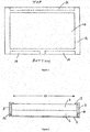
Figure 1 shows a plan, front view of an apparatus according to an embodiment of the present invention; -
Figure 2 shows a cross-sectional view of an apparatus according to an embodiment of the present invention; -
Figure 3 shows a more detailed cross-sectional view of part of the apparatus ofFigure 2 ; and -
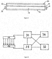
Figure 4 schematically shows circuitry for use with an embodiment of the present invention. - An embodiment of the present invention is described in detail hereunder for the example of a flat panel display apparatus employing an edge-lit backlight module as the light source, but the same technique can be used with other types of light sources. Similarly, the embodiment is described for the example of a thin-film-transistor liquid crystal display (TFT-LCD), but the same technique can also be used with other types of displays using light sources.
- With reference to
Figures 1 to 3 , a display apparatus according to an example embodiment of the present invention comprises a housing 2 including a support structure 4 supporting at least a back-light system 6 and a TFT-LCD module 8. As discussed below, the support structure 4 also supports photovoltaic cells and control circuitry. - The TFT-
LCD module 8 may, for example, be any conventional TFT-LCD module including at least a liquid crystal material contained between two components uniformly spaced apart by a predetermined distance, and an array of thin-film-transistors (TFTs) for individually controlling an optical property of pixel portions of the liquid crystal material, whereby the degree to which the liquid crystal material transmits light from the backlight system 6 can be electrically controlled for each pixel portion. The TFT-LCD module 8 defines anemission area 10 from which light is emitted via the liquid crystal material under the control of the TFT array. The housing 2 includes abezel portion 12 which frames theemission area 10 and hides parts of the apparatus outside the emission area. - The backlight system 6 includes
LED bars 14 mounted on aside wall 3 of the housing 2 at the edge of the display apparatus that is the bottom edge when the display apparatus is in use. The backlight system 6 also includes a stack of elements extending across at least the whole of theemission area 10. - In order of remoteness from the TFT-LCD module, the stack of elements comprises: (i) a reflector sheet 16 (most remote from the TFT-LCD module); (ii) light guide plate (LGP) 18; (iii) a
diffuser sheet 20; (iv) aprism sheet 22; and a reflective polariser 24 (closest to the TFT-LCD module 8). - The
LED bars 14 are aligned with one or more lateral edges of the LGP 18. In use, light emitted from theLED bars 14 propagates in a direction parallel to the plane of theLGP 18 by the mechanism of total internal reflection (TIR). The top and/or bottom surfaces of theLGP 18 includes microstructures (not shown) across the whole of the emission area. These microstructures are designed to frustrate TIR and release a portion of the light propagating through the LGP out of the LGP. - Light emerges from the
LGP 18 in a direction towards the TFT-LCD module and a direction away from the TFT-LCD module. Light emerging from theLGP 18 in a direction away from the TFT-LCD module is reflected by thereflector sheet 16 back through theLGP 18 and towards the TFT-LCD module. - The
diffuser sheet 20 increases the uniformity of distribution of light by a scattering mechanism; and theprism sheet 22 increases the proportion of light propagating in a direction substantially perpendicular to the plane of the TFT-LCD module. - The reflective polariser selectively transmits light having the right polarisation for the TFT-LCD module (i.e. light having a polarisation that is transmitted by the rear polariser of the TFT-LCD module), and reflects light having any other polarisation for recycling.
- One or more
photovoltaic devices 26 are mounted on the housing side wall opposite to the housing side wall on which theLED bars 14 are mounted. The active elements of the one or morephotovoltaic devices 26 are aligned with a lateral edge of theLGP 18, to best receive light propagating all the way across the emission area from theLED bars 14. - When the display apparatus is on and the
LED bars 14 are emitting light, the electrical energy generated by the photovoltaic devices is fed to acharge controller 28. Thecharge controller 28 regulates the voltage generated by the photovoltaic devices to a required voltage level for themain board 30 in standby mode, and stored inbattery 32. The functions of themain board 30 include e.g. controlling the TFT-LCD module based on video signals from one or more inputs, and processing user operations in standby mode, such as processing signals from a remote control unit. - When e.g. a user of the display apparatus activates a standby mode switch, a standby signal is sent from the
main board 30 to thecharge controller 28, and thecharge controller 28 sends a control signal disabling thepower board 34. Thepower board 34 functions to generate the voltages required for operation of the e.g. TFT-LCD module and backlight module from the ac power input voltage. Thebattery 32 then provides all necessary power for themain board 30 in standby mode; themain board 30 takes no power from thepower board 34 in standby mode. - The above-described display apparatus may comprise additional components other than those described above. For example, the above-described display apparatus may form part of a television set including e.g. a radio receiver for extracting video and audio signals from broadcast TV radio transmissions.
- The examples described herein are to be understood as illustrative examples of embodiments of the invention. Further embodiments and examples are envisaged. Any feature described in relation to any one example or embodiment may be used alone or in combination with other features. In addition, any feature described in relation to any one example or embodiment may also be used in combination with one or more features of any other of the examples or embodiments, or any combination of any other of the examples or embodiments. Furthermore, equivalents and modifications not described herein may also be employed within the scope of the invention, which is defined in the claims.
Claims (14)
- A display apparatus, comprising: one or more electro-optic devices for controlling the transmission of light of one or more light sources out from an emission area; wherein the display apparatus further comprises one or more photovoltaic devices located laterally outside the emission area for receiving a portion of the light from said one or more light sources.
- A display apparatus according to claim 1, wherein said one or more light sources comprise one or more light emitting devices located beyond at least one lateral edge of the emission area, and at least one light guide for propagating light from the one or more light emitting devices across the emission area and releasing a portion of the propagating light towards the one or more electro-optic devices; and wherein the one or more photovoltaic devices comprise one or more photovoltaic devices located beyond an opposite lateral edge of the emission area for receiving light propagating completely across the emission area.
- A display apparatus according to claim 2, further comprising a reflector on the opposite side of the light guide to the one or more electro-optic devices, for redirecting back towards the one or more optic devices any light released from the light guide in a direction away from the one or more electro-optic devices.
- A display apparatus according to any preceding claim, further comprising a housing with side walls extending in a direction substantially perpendicular to the emission area, and wherein the one or more light sources comprise one or more light-emitting devices mounted on at least a first side wall, and said one or more photovoltaic devices comprise one or more photovoltaic devices mounted on at least a second side wall opposite to said first side wall.
- A display apparatus according to any of claims 2 to 4, wherein the one or more light-emitting devices comprise one or more light-emitting diodes (LEDs).
- A display apparatus according to any preceding claim, wherein the one or more electro-optic devices comprises a liquid crystal medium, and an array of electronic switching devices for controlling one or more optical properties of respective areas of the liquid crystal medium.
- A display apparatus according to any preceding claim, further comprising circuitry for storing electrical energy generated by the one or more photovoltaic devices in one or more batteries, and circuitry for using electrical energy from said one or more batteries for standby operation of the display apparatus.
- A method of operating a display apparatus comprising one or more electro-optic devices for controlling the transmission of light of one or more light sources out from an emission area; wherein the method comprises operating the display apparatus in a standby mode using electrical energy generated by one or more photovoltaic devices located laterally outside the emission area for receiving a portion of the light from said one or more light sources.
- A method according to claim 8, wherein said one or more light sources comprise one or more light emitting devices located beyond at least one lateral edge of the emission area, and at least one light guide for propagating light from the one or more light emitting devices across the emission area and releasing a portion of the propagating light towards the one or more electro-optic devices; and wherein the one or more photovoltaic devices comprise one or more photovoltaic devices located beyond an opposite lateral edge of the emission area for receiving light propagating completely across the emission area.
- A method according to claim 9, wherein the display apparatus further comprises a reflector on the opposite side of the light guide to the one or more electro-optic devices, for redirecting back towards the one or more optic devices any light released from the light guide in a direction away from the one or more electro-optic devices.
- A method according to any of claims 8 to 10, wherein the display apparatus further comprises a housing with side walls extending in a direction substantially perpendicular to the emission area, and wherein the one or more light sources comprise one or more light-emitting devices mounted on at least a first side wall, and said one or more photovoltaic devices comprise one or more photovoltaic devices mounted on at least a second side wall opposite to said first side wall.
- A method according to any of claims 9 to 13, wherein the one or more light-emitting devices comprise one or more light-emitting diodes (LEDs).
- A method according to any of claims 8 to 12, wherein the one or more electro-optic devices comprises a liquid crystal medium, and an array of electronic switching devices for controlling one or more optical properties of respective areas of the liquid crystal medium.
- A method according to any of claims 8 to 13, wherein the display apparatus further comprises circuitry for storing electrical energy generated by the one or more photovoltaic devices in one or more batteries, and circuitry for using electrical energy from said one or more batteries for standby operation of the display apparatus.
Priority Applications (1)
| Application Number | Priority Date | Filing Date | Title |
|---|---|---|---|
| EP17163653.3A EP3382448A1 (en) | 2017-03-29 | 2017-03-29 | Display apparatus |
Applications Claiming Priority (1)
| Application Number | Priority Date | Filing Date | Title |
|---|---|---|---|
| EP17163653.3A EP3382448A1 (en) | 2017-03-29 | 2017-03-29 | Display apparatus |
Publications (1)
| Publication Number | Publication Date |
|---|---|
| EP3382448A1 true EP3382448A1 (en) | 2018-10-03 |
Family
ID=58454983
Family Applications (1)
| Application Number | Title | Priority Date | Filing Date |
|---|---|---|---|
| EP17163653.3A Withdrawn EP3382448A1 (en) | 2017-03-29 | 2017-03-29 | Display apparatus |
Country Status (1)
| Country | Link |
|---|---|
| EP (1) | EP3382448A1 (en) |
Citations (3)
| Publication number | Priority date | Publication date | Assignee | Title |
|---|---|---|---|---|
| JP2003084281A (en) * | 2001-09-12 | 2003-03-19 | Sharp Corp | Mobile terminal equipment |
| JP2011014513A (en) * | 2009-07-01 | 2011-01-20 | Ttt:Kk | Backlight unit having power recovery function |
| US20110069238A1 (en) | 2009-09-21 | 2011-03-24 | Sony Corporation | Embedded recycle circuit for harnessing light energy |
-
2017
- 2017-03-29 EP EP17163653.3A patent/EP3382448A1/en not_active Withdrawn
Patent Citations (3)
| Publication number | Priority date | Publication date | Assignee | Title |
|---|---|---|---|---|
| JP2003084281A (en) * | 2001-09-12 | 2003-03-19 | Sharp Corp | Mobile terminal equipment |
| JP2011014513A (en) * | 2009-07-01 | 2011-01-20 | Ttt:Kk | Backlight unit having power recovery function |
| US20110069238A1 (en) | 2009-09-21 | 2011-03-24 | Sony Corporation | Embedded recycle circuit for harnessing light energy |
Similar Documents
| Publication | Publication Date | Title |
|---|---|---|
| KR101807442B1 (en) | Backlight module and liquid crystal display device using backlight module | |
| KR101594620B1 (en) | Back light unit and liquid crystal display device having the same | |
| US20110273642A1 (en) | Backlight unit and liquid crystal display using the same | |
| US7907238B2 (en) | Backlight unit and display device using the same | |
| TWI273317B (en) | Backlight module for a double-sided LCD device | |
| US20130322119A1 (en) | Backlight Module | |
| US7760283B2 (en) | Display device using external light | |
| CN101231400A (en) | Double screen liquid crystal dispaly apparatus and notebook computer | |
| KR20080086274A (en) | Liquid crystal display device | |
| WO2015051559A1 (en) | Led backlight module and corresponding liquid crystal display | |
| KR101274714B1 (en) | Back light unit | |
| US20190123592A1 (en) | Wireless charging device and display device | |
| US7750993B2 (en) | Display device using light source and external light and having display unit hinged with main body | |
| US8905620B2 (en) | Backlight module | |
| US20170090107A1 (en) | Backlight module and liquid crystal display device | |
| KR101323567B1 (en) | Back light unit for display device | |
| CN105579895A (en) | Display device | |
| CN216083344U (en) | Backlight module and display device | |
| KR20060034528A (en) | Display device that can adjust the height of display panel | |
| KR20070119453A (en) | Backlight Unit of LCD | |
| US9004739B2 (en) | Backlight module | |
| CN106647021A (en) | Direct type backlight module | |
| KR20160063522A (en) | Light orientation angle controler and backlight unit having the same | |
| KR101023719B1 (en) | Removable LCD | |
| KR20070000125A (en) | Liquid crystal display |
Legal Events
| Date | Code | Title | Description |
|---|---|---|---|
| PUAI | Public reference made under article 153(3) epc to a published international application that has entered the european phase |
Free format text: ORIGINAL CODE: 0009012 |
|
| STAA | Information on the status of an ep patent application or granted ep patent |
Free format text: STATUS: THE APPLICATION HAS BEEN PUBLISHED |
|
| AK | Designated contracting states |
Kind code of ref document: A1 Designated state(s): AL AT BE BG CH CY CZ DE DK EE ES FI FR GB GR HR HU IE IS IT LI LT LU LV MC MK MT NL NO PL PT RO RS SE SI SK SM TR |
|
| AX | Request for extension of the european patent |
Extension state: BA ME |
|
| STAA | Information on the status of an ep patent application or granted ep patent |
Free format text: STATUS: THE APPLICATION IS DEEMED TO BE WITHDRAWN |
|
| 18D | Application deemed to be withdrawn |
Effective date: 20190404 |