EP3382248A1 - Rotary actuation mechanism - Google Patents
Rotary actuation mechanism Download PDFInfo
- Publication number
- EP3382248A1 EP3382248A1 EP17461515.3A EP17461515A EP3382248A1 EP 3382248 A1 EP3382248 A1 EP 3382248A1 EP 17461515 A EP17461515 A EP 17461515A EP 3382248 A1 EP3382248 A1 EP 3382248A1
- Authority
- EP
- European Patent Office
- Prior art keywords
- actuation mechanism
- valve
- drive
- rotary
- valve assembly
- Prior art date
- Legal status (The legal status is an assumption and is not a legal conclusion. Google has not performed a legal analysis and makes no representation as to the accuracy of the status listed.)
- Granted
Links
- 230000007246 mechanism Effects 0.000 title claims abstract description 27
- 230000008878 coupling Effects 0.000 claims description 15
- 238000010168 coupling process Methods 0.000 claims description 15
- 238000005859 coupling reaction Methods 0.000 claims description 15
- 239000000463 material Substances 0.000 description 3
- 230000000717 retained effect Effects 0.000 description 3
- 238000010276 construction Methods 0.000 description 2
- 229910052751 metal Inorganic materials 0.000 description 2
- 239000002184 metal Substances 0.000 description 2
- 229910000831 Steel Inorganic materials 0.000 description 1
- 238000004378 air conditioning Methods 0.000 description 1
- 239000004411 aluminium Substances 0.000 description 1
- 229910052782 aluminium Inorganic materials 0.000 description 1
- XAGFODPZIPBFFR-UHFFFAOYSA-N aluminium Chemical compound [Al] XAGFODPZIPBFFR-UHFFFAOYSA-N 0.000 description 1
- 238000005266 casting Methods 0.000 description 1
- 230000008859 change Effects 0.000 description 1
- 239000011248 coating agent Substances 0.000 description 1
- 238000000576 coating method Methods 0.000 description 1
- 230000000295 complement effect Effects 0.000 description 1
- 239000012530 fluid Substances 0.000 description 1
- 238000005495 investment casting Methods 0.000 description 1
- 239000010687 lubricating oil Substances 0.000 description 1
- 238000012423 maintenance Methods 0.000 description 1
- 238000012986 modification Methods 0.000 description 1
- 230000004048 modification Effects 0.000 description 1
- 239000010959 steel Substances 0.000 description 1
Images




Classifications
-
- F—MECHANICAL ENGINEERING; LIGHTING; HEATING; WEAPONS; BLASTING
- F16—ENGINEERING ELEMENTS AND UNITS; GENERAL MEASURES FOR PRODUCING AND MAINTAINING EFFECTIVE FUNCTIONING OF MACHINES OR INSTALLATIONS; THERMAL INSULATION IN GENERAL
- F16K—VALVES; TAPS; COCKS; ACTUATING-FLOATS; DEVICES FOR VENTING OR AERATING
- F16K1/00—Lift valves or globe valves, i.e. cut-off apparatus with closure members having at least a component of their opening and closing motion perpendicular to the closing faces
- F16K1/16—Lift valves or globe valves, i.e. cut-off apparatus with closure members having at least a component of their opening and closing motion perpendicular to the closing faces with pivoted closure-members
- F16K1/18—Lift valves or globe valves, i.e. cut-off apparatus with closure members having at least a component of their opening and closing motion perpendicular to the closing faces with pivoted closure-members with pivoted discs or flaps
- F16K1/22—Lift valves or globe valves, i.e. cut-off apparatus with closure members having at least a component of their opening and closing motion perpendicular to the closing faces with pivoted closure-members with pivoted discs or flaps with axis of rotation crossing the valve member, e.g. butterfly valves
- F16K1/221—Lift valves or globe valves, i.e. cut-off apparatus with closure members having at least a component of their opening and closing motion perpendicular to the closing faces with pivoted closure-members with pivoted discs or flaps with axis of rotation crossing the valve member, e.g. butterfly valves specially adapted operating means therefor
-
- F—MECHANICAL ENGINEERING; LIGHTING; HEATING; WEAPONS; BLASTING
- F16—ENGINEERING ELEMENTS AND UNITS; GENERAL MEASURES FOR PRODUCING AND MAINTAINING EFFECTIVE FUNCTIONING OF MACHINES OR INSTALLATIONS; THERMAL INSULATION IN GENERAL
- F16K—VALVES; TAPS; COCKS; ACTUATING-FLOATS; DEVICES FOR VENTING OR AERATING
- F16K27/00—Construction of housing; Use of materials therefor
- F16K27/02—Construction of housing; Use of materials therefor of lift valves
- F16K27/0209—Check valves or pivoted valves
- F16K27/0218—Butterfly valves
-
- F—MECHANICAL ENGINEERING; LIGHTING; HEATING; WEAPONS; BLASTING
- F16—ENGINEERING ELEMENTS AND UNITS; GENERAL MEASURES FOR PRODUCING AND MAINTAINING EFFECTIVE FUNCTIONING OF MACHINES OR INSTALLATIONS; THERMAL INSULATION IN GENERAL
- F16K—VALVES; TAPS; COCKS; ACTUATING-FLOATS; DEVICES FOR VENTING OR AERATING
- F16K31/00—Actuating devices; Operating means; Releasing devices
- F16K31/02—Actuating devices; Operating means; Releasing devices electric; magnetic
- F16K31/04—Actuating devices; Operating means; Releasing devices electric; magnetic using a motor
- F16K31/041—Actuating devices; Operating means; Releasing devices electric; magnetic using a motor for rotating valves
- F16K31/043—Actuating devices; Operating means; Releasing devices electric; magnetic using a motor for rotating valves characterised by mechanical means between the motor and the valve, e.g. lost motion means reducing backlash, clutches, brakes or return means
-
- F—MECHANICAL ENGINEERING; LIGHTING; HEATING; WEAPONS; BLASTING
- F16—ENGINEERING ELEMENTS AND UNITS; GENERAL MEASURES FOR PRODUCING AND MAINTAINING EFFECTIVE FUNCTIONING OF MACHINES OR INSTALLATIONS; THERMAL INSULATION IN GENERAL
- F16K—VALVES; TAPS; COCKS; ACTUATING-FLOATS; DEVICES FOR VENTING OR AERATING
- F16K31/00—Actuating devices; Operating means; Releasing devices
- F16K31/44—Mechanical actuating means
- F16K31/53—Mechanical actuating means with toothed gearing
- F16K31/54—Mechanical actuating means with toothed gearing with pinion and rack
-
- F—MECHANICAL ENGINEERING; LIGHTING; HEATING; WEAPONS; BLASTING
- F16—ENGINEERING ELEMENTS AND UNITS; GENERAL MEASURES FOR PRODUCING AND MAINTAINING EFFECTIVE FUNCTIONING OF MACHINES OR INSTALLATIONS; THERMAL INSULATION IN GENERAL
- F16K—VALVES; TAPS; COCKS; ACTUATING-FLOATS; DEVICES FOR VENTING OR AERATING
- F16K1/00—Lift valves or globe valves, i.e. cut-off apparatus with closure members having at least a component of their opening and closing motion perpendicular to the closing faces
- F16K1/16—Lift valves or globe valves, i.e. cut-off apparatus with closure members having at least a component of their opening and closing motion perpendicular to the closing faces with pivoted closure-members
- F16K1/18—Lift valves or globe valves, i.e. cut-off apparatus with closure members having at least a component of their opening and closing motion perpendicular to the closing faces with pivoted closure-members with pivoted discs or flaps
- F16K1/22—Lift valves or globe valves, i.e. cut-off apparatus with closure members having at least a component of their opening and closing motion perpendicular to the closing faces with pivoted closure-members with pivoted discs or flaps with axis of rotation crossing the valve member, e.g. butterfly valves
- F16K1/224—Details of bearings for the axis of rotation
Definitions
- the present disclosure relates to a rotary actuation mechanism, more particularly but not exclusively for a rotary valve, for example a butterfly valve or ball valve.
- a typical rotary valve comprises a valve element which is rotatably mounted in a flow passage.
- the valve element rotates between an open position in which the valve element permits flow through the flow passage and a closed position in which the valve element extends across the flow passage to block the flow through the flow passage.
- the valve element is a disc which rotates between a position in which it is edge-on to the flow, providing a minimal obstruction to flow, thereby leading to a low pressure drop across the valve, and a closed position in which the disc blocks the flow passage.
- the valve element may be held at positions intermediate the open and closed positions in order to regulate the flow through the flow passage.
- valve element is rotated by a suitable actuation mechanism externally of the flow passage.
- actuation mechanisms may be complicated, heavy and expensive.
- the mechanism comprises an electric drive motor coupled to a threaded drive spindle.
- a threaded drive nut is received on the drive spindle for movement along the drive spindle.
- a telescopic drive link is further provided having a first element rotationally coupled to said drive nut and a second element rotationally fixedly couplable to the rotary element for rotationally driving the rotary element.
- One of the first and second elements is telescopically received within the other of the first and second elements.
- the first element i.e. the element attached to the drive nut is slidably received within the second element.
- the telescopic element may comprising a bearing between the first and second elements.
- the bearing may be a sliding bearing.
- the bearing may be a low friction liner.
- the drive nut may comprise a mounting pin projecting therefrom, with the first element being rotationally mounted over the mounting pin.
- the second element may be rotationally fixedly coupled with a coupling portion of a drive shaft of the rotary element.
- a non-circular section coupling for example a D-shaped, square or splined coupling, may be provided between the second element and the coupling portion of the rotary drive shaft.
- the disclosure also provides a rotary valve assembly comprising a valve element rotatably mountable within a flow passage for rotary motion between an open position in which it permits flow through the flow passage and a closed position in which it blocks flow through the flow passage.
- the valve assembly further comprises an actuation mechanism in accordance with the disclosure, the second element of the telescopic link being drivingly coupled to the valve element.
- the valve element may comprise a disc.
- the valve assembly may further comprise a valve housing comprising a duct portion receiving the valve element and an actuator portion receiving the actuation mechanism.
- the actuator portion may be integral with the duct portion. In other embodiments, however, the actuator portion may be separate from and mounted to the duct portion.
- the actuation portion may comprise a portion overhanging a side of said duct portion, the drive motor being at least partially arranged in the overhanging portion.
- the valve assembly may further comprise a cover closing the actuation portion.
- the cover may comprises an electrical connector for connection of a power supply to the electric drive motor.
- the duct portion of the valve housing may comprise mounting flanges at opposed ends thereof.
- a rotary valve assembly 2 comprises a valve housing 4, a rotary valve element 6 and a rotary actuation mechanism 8 for rotating the valve element 6.
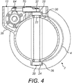
- the valve housing 4 comprises a duct portion 10 and an actuator portion 12. As can be seen in Figure 4 for example, the valve element 6 is received within the duct portion 10 and the actuation mechanism 8 received within the actuator portion 12. The actuator portion 12 is closed by a cover 14 as will be described further below.
- the duct portion 10 defines a flow passage 16 and mounting flanges 18 at opposed ends thereof to allow it to be mounted to adjacent ducts by coupling means not illustrated.
- the flanges 18 and flanges of the adjacent ducts may be provided with a series of holes for receiving mounting bolts or the like.
- the mounting flanges 18 may be clamped to flanges of the adjacent ducts by external clamps.
- the duct portion 10 and the actuator portion 12 of the valve housing 4 are formed integrally, for example by a casting process such as investment casting, although a multi-part construction also falls within the scope of this disclosure.
- the material of the valve housing 4 may be chosen in accordance with the intended application. It may, for example, by aluminium or steel.
- the valve assembly 2 illustrated in this embodiment is a butterfly valve, with the valve element 6 being a disc which is rotatable about an axis A within the flow passage 16 between a closed position (illustrated in Figures 5 to 7 ) in which the valve element 6 extends across the flow passage 16 to prevent flow through the flow passage 16 and an open position (illustrated in Figure 8 to 10 ) in which it is rotated through 90° so as to be positioned to edge-on to the flow to allow flow through the duct 16.
- the valve element 6 may also be moved to intermediate positions between the open position and the closed position so as to regulate the flow through the flow passage 16.
- the valve element 6 is supported in the valve housing 4 by first and second trunnions 20, 22.
- the trunnions 20, 22 may be formed integrally with the valve element 6 or suitably attached thereto.
- the first trunnion 20 is rotatably supported in a first bearing 24 mounted in a first recess 26 provided on the valve housing 4.
- the second trunnion 22 is supported in a second bearing 28 mounted in a second recess 30 of the valve housing 4.
- the second trunnion 22 comprises a coupling portion 32 for connection to the actuation mechanism 8 as will be described further below.
- the actuation mechanism 8 comprises an electric rotary actuator 40 which is mounted in the actuator portion 12 of the valve housing 4 by means of a mounting bracket 42 fastened to a mounting boss 44 of the valve housing 4 by fasteners 46.
- the actuation portion 12 of the valve housing 4 comprises an overhanging portion 38 which laterally overhangs the duct portion 10 of the valve housing 4.
- the actuator 40, and in particular its motor 48, is arranged at least partially within this overhanging portion 38, which allows the valve housing 4 to have a relatively low vertical profile.
- the rotary actuator 40 comprises a threaded drive spindle 50 extending from an electric drive motor 48.
- a distal end 52 of the drive spindle 50 is received in a bearing 54 which is mounted to the valve housing 4 by means of a mounting bracket 56.
- the mounting bracket 56 is attached to the valve housing 4 by means of fasteners 58.
- the longitudinal axis B of the drive spindle 50 is perpendicular to the rotational axis A of the valve element 6, as can best be seen from Figure 6 .
- the rotational speed of the drive motor 48 and the pitch of the drive spindle thread can be chosen to provide a desired rotational speed of the valve element 6.
- An internally threaded drive nut 60 is threadably received on the drive spindle 50.
- the drive nut 60 comprises an upper surface 62 from which extends a cylindrical mounting pin 64.
- the mounting pin 64 may have an enlarged head or circumferential groove formed adjacent a distal end 66 for receiving a circlip 68.
- a telescopic drive link 70 couples the drive nut 60 to the valve element 6.
- the drive link comprises a first element 72 which is slidably received within a second element 74.
- the first, inner element 72 is coupled to the drive nut 60 and the second, outer element linear rack gear 62 is coupled to the valve element 6.
- inner and outer elements 72, 74 may be coupled to the valve element 6 and drive nut 60 respectively.
- the second, outer element 74 has a bore 76 which slidably receives a shaft portion 78 of the first, inner element 72.
- the bore 76 and shaft portion 78 may have respective cross sections such that the shaft portion 78 may only slide, and not rotate within the bore 76.
- the bore 76 and shaft portion 78 may, most simply have circular cross-sectional shapes. Of course, this is not essential and the bore and shaft may non-circular complementary cross sections.
- the first and second elements may be of any suitable materials.
- both elements may be metallic.
- Other material combinations are possible, however, for example plastic-metal, plastic-plastic and so on.
- a bearing for example a sliding bearing, may be provided between the inner and outer elements 72, 74.
- the bearing could be, for example, comprise a coating or low friction liner provided on one or both of the shaft portion 78 and bore 76.
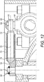
- a liner 79 is illustrated schematically in Figure 12 .
- the first element 72 further comprises a head 80 which has a circular opening 82 formed therethrough which is received over the mounting pin 64 of the drive nut so as to be rotatable or pivotable thereabout.
- the first element 72 is retained on the mounting pin 64 by the circlip 68, although other means of retaining the first element 72 may be used, for example a nut and washer.
- the first element 72 is therefore able to rotate around the axis of mounting pin 64, but is unable to rotate out of its own plane.
- the second element 74 has a head 84 which is received over the coupling portion 32 of the valve element trunnion 22.
- the head 84 is retained on the coupling portion by a circlip 86, although other retaining means, for example a nut and washer may be used.
- the coupling portion 32 of the second trunnion 22 and the head 84 may have any suitable drive coupling for example a D-shaped, square or splined coupling.
- the telescopic link 70 lies generally horizontally, i.e. perpendicular to the axis A of the valve element 6 and parallel to the axis B of the drive shaft 50 and is retained in this plane by virtue of the relative positions of its mountings to the drive nut 60 and valve element 6 as shown, for example, in Figure 6 .
- the mounting locations are co-planar.
- valve housing 4 is closed by a cover 14.
- the cover 14 may comprise an electrical connector 90 for connection of an electrical supply to the electric motor 48 of the actuator 40.
- the electrical connection may be provided on another part of the valve housing 4.
- the drive nut 60 is positioned adjacent to a proximal end of the drive spindle 50.
- the drive nut 60 will move along the drive spindle 50.
- the drive nut 60 will only be able to move along drive spindle 50, and not about it, due to the telescopic linkage 70 which will prevent such a rotational movement of the drive nut 60. This is advantageous in that it avoids the need for any additional nut anti-rotation mechanism, thereby simplifying the mechanism.
- Axial movement of the drive nut 60 along the drive spindle 50 causes the telescopic link 70 to rotate about the mounting pin 64, the telescopic link 70 then causing rotation of the valve element 6.
- the distance between the nut mounting pin 64 and the valve element coupling 32 will vary. However, this variation is accommodated by the change in length of the telescopic link 70.
- the speed of valve opening will be determined by the rotational speed of the actuator motor 48 and the pitch of the gear teeth 92, 94. Also, the valve element 6 may be stopped at any position intermediate its end positions to regulate flow through the duct 16.
- the use of an electric motor 48 facilitates this and may provide for accurate angular positioning of the valve element.
- the motor 48 may be provided with a resolver which will accurately count the revolutions of the motor 48, thereby allowing accurate determination of the movement of the drive nut 60.
- a resolver may be mounted at an end of the motor 48.
- the rate of rotation of the telescopic link 70, and therefore the rate of rotation of the valve element 6 will be greatest when the link 70 is fully extended, i.e. when the drive nut 60 is at the respective ends of the drive spindle 50. This corresponds to positions in which the valve element is fully opened or fully closed. This may be advantageous to allow rapid initial movement of the valve element 6 from those positions. If a more constant opening speed is required, the speed of the motor 48 may be controlled appropriately.
- the valve element 6 may be held in its operative position by suitable locking means.
- the drive spindle 50 may be locked in position by a mechanical lock (not shown).
- the motor 48 may be locked electrically.
- stops may be provided.
- stops or bumpers may be provided which engage the drive nut 60 or telescopic link 70.
- the stops may be formed in, or mounted to, the valve housing 4 and/or on the mounting bracket 42 and mounting bracket 56, for example.
- the disclosed embodiment may also be advantageous from a cost point of view as the individual components are easily sourced and may be easily assembled. Also, the arrangement may not need any liquid lubricants, leading to reduced maintenance and longer product life.
- the disclosure has much broader application.
- the actuation mechanism 8 may be used in other rotary valves such as port valves, or in any other equipment where a rotary actuation movement is required.
- Exemplary fields of application may include aircraft applications, for example in air conditioning systems and fluid control systems.
- the disclosure also has application to non-aircraft environments.
- the embodiments described can easily be adapted to various applications by appropriate choice of components.
- the speed of the drive motor 48 and the pitch of the drive spindle 50 can be chosen to provide the desired rotational speed of the valve element 6.
- the desired angle of rotation of the driven element such as the valve element 6 may be chosen to suit the particular application. This can be achieved by a suitable choice of the spindle pitch and length.
Landscapes
- Engineering & Computer Science (AREA)
- General Engineering & Computer Science (AREA)
- Mechanical Engineering (AREA)
- Electrically Driven Valve-Operating Means (AREA)
- Mechanically-Actuated Valves (AREA)
- Lift Valve (AREA)
Abstract
Description
- The present disclosure relates to a rotary actuation mechanism, more particularly but not exclusively for a rotary valve, for example a butterfly valve or ball valve.
- Rotary valves are widely known. A typical rotary valve comprises a valve element which is rotatably mounted in a flow passage. The valve element rotates between an open position in which the valve element permits flow through the flow passage and a closed position in which the valve element extends across the flow passage to block the flow through the flow passage. In a butterfly valve, the valve element is a disc which rotates between a position in which it is edge-on to the flow, providing a minimal obstruction to flow, thereby leading to a low pressure drop across the valve, and a closed position in which the disc blocks the flow passage. The valve element may be held at positions intermediate the open and closed positions in order to regulate the flow through the flow passage.
- The valve element is rotated by a suitable actuation mechanism externally of the flow passage. Such actuation mechanisms may be complicated, heavy and expensive.
- Disclosed herein is an actuation mechanism for a rotary element. The mechanism comprises an electric drive motor coupled to a threaded drive spindle. A threaded drive nut is received on the drive spindle for movement along the drive spindle. A telescopic drive link is further provided having a first element rotationally coupled to said drive nut and a second element rotationally fixedly couplable to the rotary element for rotationally driving the rotary element. One of the first and second elements is telescopically received within the other of the first and second elements.
- In various embodiments, the first element, i.e. the element attached to the drive nut is slidably received within the second element.
- The telescopic element may comprising a bearing between the first and second elements. The bearing may be a sliding bearing. In various embodiments, the bearing may be a low friction liner.
- The drive nut may comprise a mounting pin projecting therefrom, with the first element being rotationally mounted over the mounting pin.
- The second element may be rotationally fixedly coupled with a coupling portion of a drive shaft of the rotary element.
- In various embodiments, a non-circular section coupling, for example a D-shaped, square or splined coupling, may be provided between the second element and the coupling portion of the rotary drive shaft.
- The disclosure also provides a rotary valve assembly comprising a valve element rotatably mountable within a flow passage for rotary motion between an open position in which it permits flow through the flow passage and a closed position in which it blocks flow through the flow passage. The valve assembly further comprises an actuation mechanism in accordance with the disclosure, the second element of the telescopic link being drivingly coupled to the valve element.
- The valve element may comprise a disc.
- The valve assembly may further comprise a valve housing comprising a duct portion receiving the valve element and an actuator portion receiving the actuation mechanism.
- The actuator portion may be integral with the duct portion. In other embodiments, however, the actuator portion may be separate from and mounted to the duct portion.
- The actuation portion may comprise a portion overhanging a side of said duct portion, the drive motor being at least partially arranged in the overhanging portion.
- The valve assembly may further comprise a cover closing the actuation portion.
- The cover may comprises an electrical connector for connection of a power supply to the electric drive motor.
- The duct portion of the valve housing may comprise mounting flanges at opposed ends thereof.
- An embodiment of this disclosure will now be described by way of example only with reference to the accompanying drawings in which:
-
Figure 1 shows a perspective view of a valve assembly incorporating an actuation mechanism in accordance with this disclosure; -
Figure 2 shows the valve assembly ofFigure 1 with a cover removed; -
Figure 3 shows a plan view ofFigure 2 ; -
Figure 4 shows a vertical cross-sectional view along the line A-A ofFigure 3 ; -
Figure 5 shows a perspective view of the valve assembly components removed from the valve housing, with the valve in a closed position; -
Figure 6 shows a side view ofFigure 5 ; -
Figure 7 shows a top plan side view ofFigure 5 ; -
Figure 8 shows a perspective view of the valve assembly components removed from the valve housing, with the valve in an open position; -
Figure 9 shows a side view ofFigure 8 ; -
Figure 10 shows a top plan side view ofFigure 8 ; -
Figure 11 shows a plan view of a valve assembly with the valve in an intermediate position; and -
Figure 12 is a sectional view taken along the line A-A ofFigure 11 . - With reference to the Figures, a
rotary valve assembly 2 comprises avalve housing 4, arotary valve element 6 and arotary actuation mechanism 8 for rotating thevalve element 6. - The
valve housing 4 comprises aduct portion 10 and anactuator portion 12. As can be seen inFigure 4 for example, thevalve element 6 is received within theduct portion 10 and theactuation mechanism 8 received within theactuator portion 12. Theactuator portion 12 is closed by acover 14 as will be described further below. - The
duct portion 10 defines aflow passage 16 and mountingflanges 18 at opposed ends thereof to allow it to be mounted to adjacent ducts by coupling means not illustrated. For example theflanges 18 and flanges of the adjacent ducts may be provided with a series of holes for receiving mounting bolts or the like. Alternatively, themounting flanges 18 may be clamped to flanges of the adjacent ducts by external clamps. - In this embodiment, the
duct portion 10 and theactuator portion 12 of thevalve housing 4 are formed integrally, for example by a casting process such as investment casting, although a multi-part construction also falls within the scope of this disclosure. The material of thevalve housing 4 may be chosen in accordance with the intended application. It may, for example, by aluminium or steel. - The
valve assembly 2 illustrated in this embodiment is a butterfly valve, with thevalve element 6 being a disc which is rotatable about an axis A within theflow passage 16 between a closed position (illustrated inFigures 5 to 7 ) in which thevalve element 6 extends across theflow passage 16 to prevent flow through theflow passage 16 and an open position (illustrated inFigure 8 to 10 ) in which it is rotated through 90° so as to be positioned to edge-on to the flow to allow flow through theduct 16. Thevalve element 6 may also be moved to intermediate positions between the open position and the closed position so as to regulate the flow through theflow passage 16. - The
valve element 6 is supported in thevalve housing 4 by first andsecond trunnions trunnions valve element 6 or suitably attached thereto. - The
first trunnion 20 is rotatably supported in a first bearing 24 mounted in afirst recess 26 provided on thevalve housing 4. Thesecond trunnion 22 is supported in a second bearing 28 mounted in asecond recess 30 of thevalve housing 4. Thesecond trunnion 22 comprises acoupling portion 32 for connection to theactuation mechanism 8 as will be described further below. - The
actuation mechanism 8 comprises anelectric rotary actuator 40 which is mounted in theactuator portion 12 of thevalve housing 4 by means of a mountingbracket 42 fastened to a mountingboss 44 of thevalve housing 4 byfasteners 46. - As can be seen from
Figure 4 , theactuation portion 12 of thevalve housing 4 comprises an overhangingportion 38 which laterally overhangs theduct portion 10 of thevalve housing 4. Theactuator 40, and in particular itsmotor 48, is arranged at least partially within this overhangingportion 38, which allows thevalve housing 4 to have a relatively low vertical profile. - The
rotary actuator 40 comprises a threadeddrive spindle 50 extending from anelectric drive motor 48. Adistal end 52 of thedrive spindle 50 is received in abearing 54 which is mounted to thevalve housing 4 by means of a mountingbracket 56. The mountingbracket 56 is attached to thevalve housing 4 by means offasteners 58. The longitudinal axis B of thedrive spindle 50 is perpendicular to the rotational axis A of thevalve element 6, as can best be seen fromFigure 6 . - The rotational speed of the
drive motor 48 and the pitch of the drive spindle thread can be chosen to provide a desired rotational speed of thevalve element 6. - An internally threaded
drive nut 60 is threadably received on thedrive spindle 50. Thedrive nut 60 comprises anupper surface 62 from which extends a cylindrical mountingpin 64. The mountingpin 64 may have an enlarged head or circumferential groove formed adjacent a distal end 66 for receiving acirclip 68. - A
telescopic drive link 70 couples thedrive nut 60 to thevalve element 6. - The drive link comprises a
first element 72 which is slidably received within asecond element 74. In this embodiment, the first,inner element 72 is coupled to thedrive nut 60 and the second, outer elementlinear rack gear 62 is coupled to thevalve element 6. Of course, in other embodiments, inner andouter elements valve element 6 and drivenut 60 respectively. - As can be seen from
Figure 12 , the second,outer element 74 has abore 76 which slidably receives ashaft portion 78 of the first,inner element 72. Thebore 76 andshaft portion 78 may have respective cross sections such that theshaft portion 78 may only slide, and not rotate within thebore 76. Thebore 76 andshaft portion 78 may, most simply have circular cross-sectional shapes. Of course, this is not essential and the bore and shaft may non-circular complementary cross sections. - The first and second elements may be of any suitable materials. For example, both elements may be metallic. Other material combinations are possible, however, for example plastic-metal, plastic-plastic and so on.
- If appropriate, for example in a metal-metal construction, a bearing, for example a sliding bearing, may be provided between the inner and
outer elements shaft portion 78 and bore 76. Aliner 79 is illustrated schematically inFigure 12 . - The
first element 72 further comprises ahead 80 which has acircular opening 82 formed therethrough which is received over the mountingpin 64 of the drive nut so as to be rotatable or pivotable thereabout. Thefirst element 72 is retained on the mountingpin 64 by thecirclip 68, although other means of retaining thefirst element 72 may be used, for example a nut and washer. Thefirst element 72 is therefore able to rotate around the axis of mountingpin 64, but is unable to rotate out of its own plane. - The
second element 74 has a head 84 which is received over thecoupling portion 32 of thevalve element trunnion 22. As shown inFigure 5 , for example, the head 84 is retained on the coupling portion by acirclip 86, although other retaining means, for example a nut and washer may be used. Thecoupling portion 32 of thesecond trunnion 22 and the head 84 may have any suitable drive coupling for example a D-shaped, square or splined coupling. - The
telescopic link 70 lies generally horizontally, i.e. perpendicular to the axis A of thevalve element 6 and parallel to the axis B of thedrive shaft 50 and is retained in this plane by virtue of the relative positions of its mountings to thedrive nut 60 andvalve element 6 as shown, for example, inFigure 6 . In this embodiment, the mounting locations are co-planar. - As mentioned above, the
valve housing 4 is closed by acover 14. Thecover 14 may comprise anelectrical connector 90 for connection of an electrical supply to theelectric motor 48 of theactuator 40. Of course in other embodiments, the electrical connection may be provided on another part of thevalve housing 4. - The operation of the valve will now be described with reference to
Figure 5 to 10 . - In the closed condition shown in
Figures 5 to 7 , thedrive nut 60 is positioned adjacent to a proximal end of thedrive spindle 50. As the drive spindle rotates, thedrive nut 60 will move along thedrive spindle 50. Thedrive nut 60 will only be able to move alongdrive spindle 50, and not about it, due to thetelescopic linkage 70 which will prevent such a rotational movement of thedrive nut 60. This is advantageous in that it avoids the need for any additional nut anti-rotation mechanism, thereby simplifying the mechanism. - Axial movement of the
drive nut 60 along thedrive spindle 50 causes thetelescopic link 70 to rotate about the mountingpin 64, thetelescopic link 70 then causing rotation of thevalve element 6. As thedrive nut 60 moves along thedrive spindle 50, the distance between thenut mounting pin 64 and thevalve element coupling 32 will vary. However, this variation is accommodated by the change in length of thetelescopic link 70. - In the intermediate position illustrated in
Figure 11 , thedrive nut 60 has moved to a mid-section of thedrive spindle 50. Thetelescopic link 70 is at its shortest length at this point and has been rotated through 45°, this rotation being translated into a 45° rotation of thevalve element 6, the valve then being partially open. - In its fully open position, illustrated in
Figures 8 to 10 , thedrive nut 60 has moved to thedistal end 62 of thedrive spindle 50. Thetelescopic link 70 has been rotated through 90°, this rotation being translated into a 90° rotation of thevalve element 6. - The speed of valve opening will be determined by the rotational speed of the
actuator motor 48 and the pitch of the gear teeth 92, 94. Also, thevalve element 6 may be stopped at any position intermediate its end positions to regulate flow through theduct 16. The use of anelectric motor 48 facilitates this and may provide for accurate angular positioning of the valve element. For example, in certain embodiments, themotor 48 may be provided with a resolver which will accurately count the revolutions of themotor 48, thereby allowing accurate determination of the movement of thedrive nut 60. In one example, a resolver may be mounted at an end of themotor 48. - It will be understood that in the embodiment illustrated, the rate of rotation of the
telescopic link 70, and therefore the rate of rotation of thevalve element 6 will be greatest when thelink 70 is fully extended, i.e. when thedrive nut 60 is at the respective ends of thedrive spindle 50. This corresponds to positions in which the valve element is fully opened or fully closed. This may be advantageous to allow rapid initial movement of thevalve element 6 from those positions. If a more constant opening speed is required, the speed of themotor 48 may be controlled appropriately. - The
valve element 6 may be held in its operative position by suitable locking means. In some embodiments thedrive spindle 50 may be locked in position by a mechanical lock (not shown). In another embodiment, themotor 48 may be locked electrically. - In addition, to prevent over rotation of the
valve element 6, hard stops may be provided. For example, stops or bumpers may be provided which engage thedrive nut 60 ortelescopic link 70. The stops may be formed in, or mounted to, thevalve housing 4 and/or on the mountingbracket 42 and mountingbracket 56, for example. - The disclosed embodiment may also be advantageous from a cost point of view as the individual components are easily sourced and may be easily assembled. Also, the arrangement may not need any liquid lubricants, leading to reduced maintenance and longer product life.
- Also, it will be appreciated that the above is a description of just one embodiment of the disclosure and that various modifications may be made thereto without departing from the scope of the disclosure.
- While described in the context of a butterfly valve, the disclosure has much broader application. For example, the
actuation mechanism 8 may be used in other rotary valves such as port valves, or in any other equipment where a rotary actuation movement is required. Exemplary fields of application may include aircraft applications, for example in air conditioning systems and fluid control systems. However, the disclosure also has application to non-aircraft environments. - The embodiments described can easily be adapted to various applications by appropriate choice of components. For example, the speed of the
drive motor 48 and the pitch of thedrive spindle 50 can be chosen to provide the desired rotational speed of thevalve element 6. - It will also be appreciated that the desired angle of rotation of the driven element such as the
valve element 6 may be chosen to suit the particular application. This can be achieved by a suitable choice of the spindle pitch and length.
Claims (15)
- An actuation mechanism (8) for a rotary element (6), comprising:an electric drive motor (48) coupled to a threaded drive spindle (50);a threaded drive nut (60) received on said drive spindle (50) for movement along said drive spindle (50);a telescopic drive link (70) having a first element (72) rotationally coupled to said drive nut (60) and a second element (74) rotationally fixedly couplable to said rotary element (6) for rotationally driving said rotary element (6), one of said first and second elements (72, 74) being telescopically received within the other of said first and second elements (72, 74).
- An actuation mechanism as claimed in claim 1, wherein said first element (72) is slidably received within the second element (74).
- An actuation mechanism as claimed in claim 1 or 2, comprising a bearing (79) between said first and second elements (72, 74).
- An actuation mechanism as claimed in claim 3, wherein said bearing is a sliding bearing (79).
- An actuation mechanism as claimed in claim 4, wherein said bearing comprises a liner (79).
- An actuation mechanism as claimed in any preceding claim, wherein said drive nut (60) comprises a mounting pin (64) projecting therefrom, said first element (72) being pivotally mounted over said mounting pin (64).
- An actuation mechanism as claimed in any preceding claim, wherein said second element (74) is rotationally fixedly coupled with a coupling portion (32) of a drive shaft of said rotary element (6).
- An actuation mechanism as claimed in claim 7, wherein a non-circular section coupling is provided between said second element (74) and said coupling portion (32) of said rotary drive shaft.
- A rotary valve assembly (2) comprising:a valve element (6) rotatably mountable within a flow passage (16) for rotary motion between an open position in which it permits flow through the flow passage (16) and a closed position in which it blocks flow through the flow passage (16); andan actuation mechanism (8) as claimed in any preceding claim, said second element drivingly coupled to said valve element (6).
- A valve assembly as claimed in claim 9, further comprising a valve housing (4) comprising a duct portion (10) receiving said valve element (6) and an actuator portion (12) receiving said actuation mechanism.
- A valve assembly as claimed in claim 10, wherein said actuator portion (12) is integral with said duct portion (10).
- A valve assembly as claimed in claim 10 or 11, wherein said actuation portion (12) comprises a portion (38) overhanging a side of said duct portion (10), said drive motor (48) being at least partially arranged in said overhanging portion (38).
- A valve assembly as claimed in any of claims 10 to 12, further comprising a cover (14) removably closing said actuation portion (12).
- A valve assembly as claimed in claim 13, wherein said cover (12) comprises an electrical connector (102) for connection of a power supply to said electric drive motor (48).
- A valve assembly as claimed in any of claims 10 to 14 wherein said duct portion (10) comprises mounting flanges (18) at opposed ends thereof.
Priority Applications (2)
| Application Number | Priority Date | Filing Date | Title |
|---|---|---|---|
| EP17461515.3A EP3382248B1 (en) | 2017-03-30 | 2017-03-30 | Rotary actuation mechanism |
| US15/939,861 US20180292012A1 (en) | 2017-03-30 | 2018-03-29 | Rotary actuation mechanism |
Applications Claiming Priority (1)
| Application Number | Priority Date | Filing Date | Title |
|---|---|---|---|
| EP17461515.3A EP3382248B1 (en) | 2017-03-30 | 2017-03-30 | Rotary actuation mechanism |
Publications (2)
| Publication Number | Publication Date |
|---|---|
| EP3382248A1 true EP3382248A1 (en) | 2018-10-03 |
| EP3382248B1 EP3382248B1 (en) | 2020-04-29 |
Family
ID=58488945
Family Applications (1)
| Application Number | Title | Priority Date | Filing Date |
|---|---|---|---|
| EP17461515.3A Not-in-force EP3382248B1 (en) | 2017-03-30 | 2017-03-30 | Rotary actuation mechanism |
Country Status (2)
| Country | Link |
|---|---|
| US (1) | US20180292012A1 (en) |
| EP (1) | EP3382248B1 (en) |
Cited By (1)
| Publication number | Priority date | Publication date | Assignee | Title |
|---|---|---|---|---|
| CN115325251A (en) * | 2022-08-12 | 2022-11-11 | 苏州纽威阀门股份有限公司 | Valve remote transmission device |
Families Citing this family (8)
| Publication number | Priority date | Publication date | Assignee | Title |
|---|---|---|---|---|
| US11306941B2 (en) * | 2018-06-12 | 2022-04-19 | Ademco Inc. | Retrofit damper optimized for universal installation |
| US11149980B2 (en) * | 2018-06-12 | 2021-10-19 | Ademco Inc. | Retrofit damper with pivoting connection between deployment and operational configurations |
| US11300319B2 (en) | 2018-06-12 | 2022-04-12 | Ademco Inc. | Retrofit damper assembly |
| US11598427B2 (en) * | 2021-01-08 | 2023-03-07 | Kennedy Valve Company | Butterfly valve |
| US12553522B1 (en) * | 2021-09-30 | 2026-02-17 | Plattco Corporation | Electric actuator for single and double flap dust valves |
| CN114704651B (en) * | 2022-04-02 | 2024-05-03 | 上海罗杰斯阀门有限公司 | Four eccentric butterfly valve |
| US20240229342A1 (en) * | 2023-01-06 | 2024-07-11 | Whirlpool Corporation | Dryer front bulkhead ventilation integration |
| KR102956515B1 (en) * | 2025-02-10 | 2026-04-24 | (주)엠티에스 | Gas valve device for burner |
Citations (7)
| Publication number | Priority date | Publication date | Assignee | Title |
|---|---|---|---|---|
| US2704947A (en) * | 1953-04-30 | 1955-03-29 | Morgan Smith S Co | Manual and automatic valve actuator with declutching unit |
| DE1814599U (en) * | 1960-05-13 | 1960-07-07 | Armaturenwerk Mosbach Heinrich | SPINDLE DRIVE FOR FITTINGS, IN PARTICULAR FLAPS. |
| US3575378A (en) * | 1969-06-18 | 1971-04-20 | Pratt Co Henry | Valve operator mechanism |
| US4008877A (en) * | 1972-11-30 | 1977-02-22 | Kubota, Ltd. | Butterfly valve apparatus |
| US20050028871A1 (en) * | 2003-08-04 | 2005-02-10 | Mitsubishi Denki Kabushiki Kaisha | Intake air control apparatus for an engine |
| EP1911951A1 (en) * | 2006-10-10 | 2008-04-16 | Magneti Marelli Powertrain S.p.A. | Throttle valve with three-phase brushless motor for an internal-combustion engine |
| CN202398586U (en) * | 2011-12-08 | 2012-08-29 | 沈阳仪表科学研究院 | Truss-type visible automatic cleaning device for internal surface of horizontal-type tank body |
Family Cites Families (13)
| Publication number | Priority date | Publication date | Assignee | Title |
|---|---|---|---|---|
| US3562347A (en) * | 1967-12-15 | 1971-02-09 | Japan Gas Chemical Co | Process for extract-isomerization of xylene isomers |
| US3774462A (en) * | 1972-04-20 | 1973-11-27 | J Thompson | Valve actuator |
| US4736670A (en) * | 1986-10-30 | 1988-04-12 | Ford Motor Company | Remotely operated fluid power control system for automotive vehicle |
| US5052424A (en) * | 1990-07-16 | 1991-10-01 | Eaton Corporation | Electrically operated servo actuator with automatic shut off |
| DE4135557C2 (en) * | 1991-10-29 | 1999-05-06 | Diehl Stiftung & Co | Rudder control device |
| US5417083A (en) * | 1993-09-24 | 1995-05-23 | American Standard Inc. | In-line incremetally adjustable electronic expansion valve |
| US7017884B2 (en) * | 2004-01-08 | 2006-03-28 | Woodward Governor Company | Fluid metering valve |
| JP4222240B2 (en) * | 2004-03-24 | 2009-02-12 | 株式会社デンソー | Control door drive |
| US7097148B2 (en) * | 2004-07-21 | 2006-08-29 | Battelle Energy Alliance, Llc | Scissor thrust valve actuator |
| US7303180B1 (en) * | 2006-12-18 | 2007-12-04 | Val Matic Valve & Mfg. Corp. | Valve actuator with split thrust bearing |
| GB201106974D0 (en) * | 2011-04-26 | 2011-06-08 | Corcost Ltd | Actuator cam |
| US9377121B2 (en) * | 2011-12-03 | 2016-06-28 | Big Horn Valve, Inc. | Leak-free rotary valve with internal worm gear |
| EP3258148B1 (en) * | 2016-06-14 | 2020-05-06 | Hamilton Sundstrand Corporation | Rotary actuation mechanism |
-
2017
- 2017-03-30 EP EP17461515.3A patent/EP3382248B1/en not_active Not-in-force
-
2018
- 2018-03-29 US US15/939,861 patent/US20180292012A1/en not_active Abandoned
Patent Citations (7)
| Publication number | Priority date | Publication date | Assignee | Title |
|---|---|---|---|---|
| US2704947A (en) * | 1953-04-30 | 1955-03-29 | Morgan Smith S Co | Manual and automatic valve actuator with declutching unit |
| DE1814599U (en) * | 1960-05-13 | 1960-07-07 | Armaturenwerk Mosbach Heinrich | SPINDLE DRIVE FOR FITTINGS, IN PARTICULAR FLAPS. |
| US3575378A (en) * | 1969-06-18 | 1971-04-20 | Pratt Co Henry | Valve operator mechanism |
| US4008877A (en) * | 1972-11-30 | 1977-02-22 | Kubota, Ltd. | Butterfly valve apparatus |
| US20050028871A1 (en) * | 2003-08-04 | 2005-02-10 | Mitsubishi Denki Kabushiki Kaisha | Intake air control apparatus for an engine |
| EP1911951A1 (en) * | 2006-10-10 | 2008-04-16 | Magneti Marelli Powertrain S.p.A. | Throttle valve with three-phase brushless motor for an internal-combustion engine |
| CN202398586U (en) * | 2011-12-08 | 2012-08-29 | 沈阳仪表科学研究院 | Truss-type visible automatic cleaning device for internal surface of horizontal-type tank body |
Cited By (1)
| Publication number | Priority date | Publication date | Assignee | Title |
|---|---|---|---|---|
| CN115325251A (en) * | 2022-08-12 | 2022-11-11 | 苏州纽威阀门股份有限公司 | Valve remote transmission device |
Also Published As
| Publication number | Publication date |
|---|---|
| EP3382248B1 (en) | 2020-04-29 |
| US20180292012A1 (en) | 2018-10-11 |
Similar Documents
| Publication | Publication Date | Title |
|---|---|---|
| EP3382248B1 (en) | Rotary actuation mechanism | |
| US10215301B2 (en) | Rotary actuation mechanism | |
| US7141752B2 (en) | Electric actuator | |
| ES2943563T3 (en) | Linear actuator with rotary position output | |
| EP3467347B1 (en) | Linear actuator | |
| US6666129B1 (en) | Operating device for a rotatable closing element of a valve | |
| US4235258A (en) | Driving device for opening and closing a valve | |
| EP1671005B1 (en) | Improved arrangement in a swing door apparatus provided with a door closer | |
| CN102308134B (en) | Manual override apparatus for linear actuators | |
| CN101263345B (en) | Adjust drive | |
| KR101558540B1 (en) | Hydraulic rotary actuator for opening and closing butterfly valve | |
| WO2007051332A3 (en) | Actuator with a reduction gear provided for an actuating element for regulate a gas or fluid flow | |
| US12516741B2 (en) | Hydraulic valve with manual override | |
| CN110735933A (en) | Valve-in-valve applied to zero power of low-pressure cylinder of steam turbine | |
| JP3054540B2 (en) | Rotary valve drive | |
| US7997539B2 (en) | Device and method for twisting and clamping moveable flaps | |
| US4779512A (en) | Rotary drive spool valve | |
| US9175770B2 (en) | Secured locking corset for shutter controlled by actuator, in particular actuator corset for aircraft door and locking method | |
| CN111425618A (en) | Low-abrasion ball valve | |
| KR101221054B1 (en) | Worm gear type valve | |
| US8296998B2 (en) | Powered actuator | |
| US4800308A (en) | Motorized control unit with torsional elastomeric bias | |
| US20110036438A1 (en) | Plug assembly with moveable mounting members | |
| CN220118754U (en) | Electric actuator | |
| EP4204719B1 (en) | Ball valve, in particular for explosion isolation in process pipelines |
Legal Events
| Date | Code | Title | Description |
|---|---|---|---|
| PUAI | Public reference made under article 153(3) epc to a published international application that has entered the european phase |
Free format text: ORIGINAL CODE: 0009012 |
|
| STAA | Information on the status of an ep patent application or granted ep patent |
Free format text: STATUS: THE APPLICATION HAS BEEN PUBLISHED |
|
| AK | Designated contracting states |
Kind code of ref document: A1 Designated state(s): AL AT BE BG CH CY CZ DE DK EE ES FI FR GB GR HR HU IE IS IT LI LT LU LV MC MK MT NL NO PL PT RO RS SE SI SK SM TR |
|
| AX | Request for extension of the european patent |
Extension state: BA ME |
|
| STAA | Information on the status of an ep patent application or granted ep patent |
Free format text: STATUS: REQUEST FOR EXAMINATION WAS MADE |
|
| 17P | Request for examination filed |
Effective date: 20190403 |
|
| RBV | Designated contracting states (corrected) |
Designated state(s): AL AT BE BG CH CY CZ DE DK EE ES FI FR GB GR HR HU IE IS IT LI LT LU LV MC MK MT NL NO PL PT RO RS SE SI SK SM TR |
|
| RAP1 | Party data changed (applicant data changed or rights of an application transferred) |
Owner name: HAMILTON SUNDSTRAND CORPORATION |
|
| GRAP | Despatch of communication of intention to grant a patent |
Free format text: ORIGINAL CODE: EPIDOSNIGR1 |
|
| STAA | Information on the status of an ep patent application or granted ep patent |
Free format text: STATUS: GRANT OF PATENT IS INTENDED |
|
| INTG | Intention to grant announced |
Effective date: 20191104 |
|
| GRAS | Grant fee paid |
Free format text: ORIGINAL CODE: EPIDOSNIGR3 |
|
| GRAA | (expected) grant |
Free format text: ORIGINAL CODE: 0009210 |
|
| STAA | Information on the status of an ep patent application or granted ep patent |
Free format text: STATUS: THE PATENT HAS BEEN GRANTED |
|
| AK | Designated contracting states |
Kind code of ref document: B1 Designated state(s): AL AT BE BG CH CY CZ DE DK EE ES FI FR GB GR HR HU IE IS IT LI LT LU LV MC MK MT NL NO PL PT RO RS SE SI SK SM TR |
|
| REG | Reference to a national code |
Ref country code: GB Ref legal event code: FG4D |
|
| REG | Reference to a national code |
Ref country code: CH Ref legal event code: EP |
|
| REG | Reference to a national code |
Ref country code: DE Ref legal event code: R096 Ref document number: 602017015632 Country of ref document: DE |
|
| REG | Reference to a national code |
Ref country code: AT Ref legal event code: REF Ref document number: 1263828 Country of ref document: AT Kind code of ref document: T Effective date: 20200515 |
|
| REG | Reference to a national code |
Ref country code: IE Ref legal event code: FG4D |
|
| REG | Reference to a national code |
Ref country code: NL Ref legal event code: MP Effective date: 20200429 |
|
| REG | Reference to a national code |
Ref country code: LT Ref legal event code: MG4D |
|
| PG25 | Lapsed in a contracting state [announced via postgrant information from national office to epo] |
Ref country code: GR Free format text: LAPSE BECAUSE OF FAILURE TO SUBMIT A TRANSLATION OF THE DESCRIPTION OR TO PAY THE FEE WITHIN THE PRESCRIBED TIME-LIMIT Effective date: 20200730 Ref country code: PT Free format text: LAPSE BECAUSE OF FAILURE TO SUBMIT A TRANSLATION OF THE DESCRIPTION OR TO PAY THE FEE WITHIN THE PRESCRIBED TIME-LIMIT Effective date: 20200831 Ref country code: IS Free format text: LAPSE BECAUSE OF FAILURE TO SUBMIT A TRANSLATION OF THE DESCRIPTION OR TO PAY THE FEE WITHIN THE PRESCRIBED TIME-LIMIT Effective date: 20200829 Ref country code: LT Free format text: LAPSE BECAUSE OF FAILURE TO SUBMIT A TRANSLATION OF THE DESCRIPTION OR TO PAY THE FEE WITHIN THE PRESCRIBED TIME-LIMIT Effective date: 20200429 Ref country code: NO Free format text: LAPSE BECAUSE OF FAILURE TO SUBMIT A TRANSLATION OF THE DESCRIPTION OR TO PAY THE FEE WITHIN THE PRESCRIBED TIME-LIMIT Effective date: 20200729 Ref country code: SE Free format text: LAPSE BECAUSE OF FAILURE TO SUBMIT A TRANSLATION OF THE DESCRIPTION OR TO PAY THE FEE WITHIN THE PRESCRIBED TIME-LIMIT Effective date: 20200429 Ref country code: FI Free format text: LAPSE BECAUSE OF FAILURE TO SUBMIT A TRANSLATION OF THE DESCRIPTION OR TO PAY THE FEE WITHIN THE PRESCRIBED TIME-LIMIT Effective date: 20200429 |
|
| REG | Reference to a national code |
Ref country code: AT Ref legal event code: MK05 Ref document number: 1263828 Country of ref document: AT Kind code of ref document: T Effective date: 20200429 |
|
| PG25 | Lapsed in a contracting state [announced via postgrant information from national office to epo] |
Ref country code: HR Free format text: LAPSE BECAUSE OF FAILURE TO SUBMIT A TRANSLATION OF THE DESCRIPTION OR TO PAY THE FEE WITHIN THE PRESCRIBED TIME-LIMIT Effective date: 20200429 Ref country code: RS Free format text: LAPSE BECAUSE OF FAILURE TO SUBMIT A TRANSLATION OF THE DESCRIPTION OR TO PAY THE FEE WITHIN THE PRESCRIBED TIME-LIMIT Effective date: 20200429 Ref country code: LV Free format text: LAPSE BECAUSE OF FAILURE TO SUBMIT A TRANSLATION OF THE DESCRIPTION OR TO PAY THE FEE WITHIN THE PRESCRIBED TIME-LIMIT Effective date: 20200429 Ref country code: BG Free format text: LAPSE BECAUSE OF FAILURE TO SUBMIT A TRANSLATION OF THE DESCRIPTION OR TO PAY THE FEE WITHIN THE PRESCRIBED TIME-LIMIT Effective date: 20200729 |
|
| PG25 | Lapsed in a contracting state [announced via postgrant information from national office to epo] |
Ref country code: AL Free format text: LAPSE BECAUSE OF FAILURE TO SUBMIT A TRANSLATION OF THE DESCRIPTION OR TO PAY THE FEE WITHIN THE PRESCRIBED TIME-LIMIT Effective date: 20200429 Ref country code: NL Free format text: LAPSE BECAUSE OF FAILURE TO SUBMIT A TRANSLATION OF THE DESCRIPTION OR TO PAY THE FEE WITHIN THE PRESCRIBED TIME-LIMIT Effective date: 20200429 |
|
| PG25 | Lapsed in a contracting state [announced via postgrant information from national office to epo] |
Ref country code: SM Free format text: LAPSE BECAUSE OF FAILURE TO SUBMIT A TRANSLATION OF THE DESCRIPTION OR TO PAY THE FEE WITHIN THE PRESCRIBED TIME-LIMIT Effective date: 20200429 Ref country code: ES Free format text: LAPSE BECAUSE OF FAILURE TO SUBMIT A TRANSLATION OF THE DESCRIPTION OR TO PAY THE FEE WITHIN THE PRESCRIBED TIME-LIMIT Effective date: 20200429 Ref country code: CZ Free format text: LAPSE BECAUSE OF FAILURE TO SUBMIT A TRANSLATION OF THE DESCRIPTION OR TO PAY THE FEE WITHIN THE PRESCRIBED TIME-LIMIT Effective date: 20200429 Ref country code: RO Free format text: LAPSE BECAUSE OF FAILURE TO SUBMIT A TRANSLATION OF THE DESCRIPTION OR TO PAY THE FEE WITHIN THE PRESCRIBED TIME-LIMIT Effective date: 20200429 Ref country code: AT Free format text: LAPSE BECAUSE OF FAILURE TO SUBMIT A TRANSLATION OF THE DESCRIPTION OR TO PAY THE FEE WITHIN THE PRESCRIBED TIME-LIMIT Effective date: 20200429 Ref country code: DK Free format text: LAPSE BECAUSE OF FAILURE TO SUBMIT A TRANSLATION OF THE DESCRIPTION OR TO PAY THE FEE WITHIN THE PRESCRIBED TIME-LIMIT Effective date: 20200429 Ref country code: EE Free format text: LAPSE BECAUSE OF FAILURE TO SUBMIT A TRANSLATION OF THE DESCRIPTION OR TO PAY THE FEE WITHIN THE PRESCRIBED TIME-LIMIT Effective date: 20200429 Ref country code: IT Free format text: LAPSE BECAUSE OF FAILURE TO SUBMIT A TRANSLATION OF THE DESCRIPTION OR TO PAY THE FEE WITHIN THE PRESCRIBED TIME-LIMIT Effective date: 20200429 |
|
| REG | Reference to a national code |
Ref country code: DE Ref legal event code: R097 Ref document number: 602017015632 Country of ref document: DE |
|
| PG25 | Lapsed in a contracting state [announced via postgrant information from national office to epo] |
Ref country code: PL Free format text: LAPSE BECAUSE OF FAILURE TO SUBMIT A TRANSLATION OF THE DESCRIPTION OR TO PAY THE FEE WITHIN THE PRESCRIBED TIME-LIMIT Effective date: 20200429 Ref country code: SK Free format text: LAPSE BECAUSE OF FAILURE TO SUBMIT A TRANSLATION OF THE DESCRIPTION OR TO PAY THE FEE WITHIN THE PRESCRIBED TIME-LIMIT Effective date: 20200429 |
|
| PLBE | No opposition filed within time limit |
Free format text: ORIGINAL CODE: 0009261 |
|
| STAA | Information on the status of an ep patent application or granted ep patent |
Free format text: STATUS: NO OPPOSITION FILED WITHIN TIME LIMIT |
|
| 26N | No opposition filed |
Effective date: 20210201 |
|
| PG25 | Lapsed in a contracting state [announced via postgrant information from national office to epo] |
Ref country code: SI Free format text: LAPSE BECAUSE OF FAILURE TO SUBMIT A TRANSLATION OF THE DESCRIPTION OR TO PAY THE FEE WITHIN THE PRESCRIBED TIME-LIMIT Effective date: 20200429 |
|
| REG | Reference to a national code |
Ref country code: DE Ref legal event code: R119 Ref document number: 602017015632 Country of ref document: DE |
|
| PG25 | Lapsed in a contracting state [announced via postgrant information from national office to epo] |
Ref country code: MC Free format text: LAPSE BECAUSE OF FAILURE TO SUBMIT A TRANSLATION OF THE DESCRIPTION OR TO PAY THE FEE WITHIN THE PRESCRIBED TIME-LIMIT Effective date: 20200429 |
|
| REG | Reference to a national code |
Ref country code: CH Ref legal event code: PL |
|
| GBPC | Gb: european patent ceased through non-payment of renewal fee |
Effective date: 20210330 |
|
| REG | Reference to a national code |
Ref country code: BE Ref legal event code: MM Effective date: 20210331 |
|
| PG25 | Lapsed in a contracting state [announced via postgrant information from national office to epo] |
Ref country code: FR Free format text: LAPSE BECAUSE OF NON-PAYMENT OF DUE FEES Effective date: 20210331 Ref country code: IE Free format text: LAPSE BECAUSE OF NON-PAYMENT OF DUE FEES Effective date: 20210330 Ref country code: GB Free format text: LAPSE BECAUSE OF NON-PAYMENT OF DUE FEES Effective date: 20210330 Ref country code: LU Free format text: LAPSE BECAUSE OF NON-PAYMENT OF DUE FEES Effective date: 20210330 Ref country code: LI Free format text: LAPSE BECAUSE OF NON-PAYMENT OF DUE FEES Effective date: 20210331 Ref country code: DE Free format text: LAPSE BECAUSE OF NON-PAYMENT OF DUE FEES Effective date: 20211001 Ref country code: CH Free format text: LAPSE BECAUSE OF NON-PAYMENT OF DUE FEES Effective date: 20210331 |
|
| PG25 | Lapsed in a contracting state [announced via postgrant information from national office to epo] |
Ref country code: BE Free format text: LAPSE BECAUSE OF NON-PAYMENT OF DUE FEES Effective date: 20210331 |
|
| PG25 | Lapsed in a contracting state [announced via postgrant information from national office to epo] |
Ref country code: CY Free format text: LAPSE BECAUSE OF FAILURE TO SUBMIT A TRANSLATION OF THE DESCRIPTION OR TO PAY THE FEE WITHIN THE PRESCRIBED TIME-LIMIT Effective date: 20200429 |
|
| PG25 | Lapsed in a contracting state [announced via postgrant information from national office to epo] |
Ref country code: HU Free format text: LAPSE BECAUSE OF FAILURE TO SUBMIT A TRANSLATION OF THE DESCRIPTION OR TO PAY THE FEE WITHIN THE PRESCRIBED TIME-LIMIT; INVALID AB INITIO Effective date: 20170330 |
|
| PG25 | Lapsed in a contracting state [announced via postgrant information from national office to epo] |
Ref country code: MK Free format text: LAPSE BECAUSE OF FAILURE TO SUBMIT A TRANSLATION OF THE DESCRIPTION OR TO PAY THE FEE WITHIN THE PRESCRIBED TIME-LIMIT Effective date: 20200429 |
|
| PG25 | Lapsed in a contracting state [announced via postgrant information from national office to epo] |
Ref country code: TR Free format text: LAPSE BECAUSE OF FAILURE TO SUBMIT A TRANSLATION OF THE DESCRIPTION OR TO PAY THE FEE WITHIN THE PRESCRIBED TIME-LIMIT Effective date: 20200429 |
|
| PG25 | Lapsed in a contracting state [announced via postgrant information from national office to epo] |
Ref country code: MT Free format text: LAPSE BECAUSE OF FAILURE TO SUBMIT A TRANSLATION OF THE DESCRIPTION OR TO PAY THE FEE WITHIN THE PRESCRIBED TIME-LIMIT Effective date: 20200429 |