EP3382179A1 - Gas turbine engine - Google Patents
Gas turbine engine Download PDFInfo
- Publication number
- EP3382179A1 EP3382179A1 EP18159114.0A EP18159114A EP3382179A1 EP 3382179 A1 EP3382179 A1 EP 3382179A1 EP 18159114 A EP18159114 A EP 18159114A EP 3382179 A1 EP3382179 A1 EP 3382179A1
- Authority
- EP
- European Patent Office
- Prior art keywords
- door
- expander
- configuration
- arrangement according
- arrangement
- Prior art date
- Legal status (The legal status is an assumption and is not a legal conclusion. Google has not performed a legal analysis and makes no representation as to the accuracy of the status listed.)
- Granted
Links
Images

Classifications
-
- F—MECHANICAL ENGINEERING; LIGHTING; HEATING; WEAPONS; BLASTING
- F01—MACHINES OR ENGINES IN GENERAL; ENGINE PLANTS IN GENERAL; STEAM ENGINES
- F01D—NON-POSITIVE DISPLACEMENT MACHINES OR ENGINES, e.g. STEAM TURBINES
- F01D21/00—Shutting-down of machines or engines, e.g. in emergency; Regulating, controlling, or safety means not otherwise provided for
- F01D21/14—Shutting-down of machines or engines, e.g. in emergency; Regulating, controlling, or safety means not otherwise provided for responsive to other specific conditions
-
- F—MECHANICAL ENGINEERING; LIGHTING; HEATING; WEAPONS; BLASTING
- F01—MACHINES OR ENGINES IN GENERAL; ENGINE PLANTS IN GENERAL; STEAM ENGINES
- F01D—NON-POSITIVE DISPLACEMENT MACHINES OR ENGINES, e.g. STEAM TURBINES
- F01D17/00—Regulating or controlling by varying flow
- F01D17/10—Final actuators
- F01D17/105—Final actuators by passing part of the fluid
-
- F—MECHANICAL ENGINEERING; LIGHTING; HEATING; WEAPONS; BLASTING
- F02—COMBUSTION ENGINES; HOT-GAS OR COMBUSTION-PRODUCT ENGINE PLANTS
- F02C—GAS-TURBINE PLANTS; AIR INTAKES FOR JET-PROPULSION PLANTS; CONTROLLING FUEL SUPPLY IN AIR-BREATHING JET-PROPULSION PLANTS
- F02C7/00—Features, components parts, details or accessories, not provided for in, or of interest apart form groups F02C1/00 - F02C6/00; Air intakes for jet-propulsion plants
-
- B—PERFORMING OPERATIONS; TRANSPORTING
- B64—AIRCRAFT; AVIATION; COSMONAUTICS
- B64D—EQUIPMENT FOR FITTING IN OR TO AIRCRAFT; FLIGHT SUITS; PARACHUTES; ARRANGEMENT OR MOUNTING OF POWER PLANTS OR PROPULSION TRANSMISSIONS IN AIRCRAFT
- B64D13/00—Arrangements or adaptations of air-treatment apparatus for aircraft crew or passengers, or freight space
- B64D13/02—Arrangements or adaptations of air-treatment apparatus for aircraft crew or passengers, or freight space the air being pressurised
- B64D13/04—Automatic control of pressure
-
- F—MECHANICAL ENGINEERING; LIGHTING; HEATING; WEAPONS; BLASTING
- F02—COMBUSTION ENGINES; HOT-GAS OR COMBUSTION-PRODUCT ENGINE PLANTS
- F02C—GAS-TURBINE PLANTS; AIR INTAKES FOR JET-PROPULSION PLANTS; CONTROLLING FUEL SUPPLY IN AIR-BREATHING JET-PROPULSION PLANTS
- F02C3/00—Gas-turbine plants characterised by the use of combustion products as the working fluid
- F02C3/04—Gas-turbine plants characterised by the use of combustion products as the working fluid having a turbine driving a compressor
-
- F—MECHANICAL ENGINEERING; LIGHTING; HEATING; WEAPONS; BLASTING
- F05—INDEXING SCHEMES RELATING TO ENGINES OR PUMPS IN VARIOUS SUBCLASSES OF CLASSES F01-F04
- F05D—INDEXING SCHEME FOR ASPECTS RELATING TO NON-POSITIVE-DISPLACEMENT MACHINES OR ENGINES, GAS-TURBINES OR JET-PROPULSION PLANTS
- F05D2220/00—Application
- F05D2220/30—Application in turbines
- F05D2220/32—Application in turbines in gas turbines
-
- F—MECHANICAL ENGINEERING; LIGHTING; HEATING; WEAPONS; BLASTING
- F05—INDEXING SCHEMES RELATING TO ENGINES OR PUMPS IN VARIOUS SUBCLASSES OF CLASSES F01-F04
- F05D—INDEXING SCHEME FOR ASPECTS RELATING TO NON-POSITIVE-DISPLACEMENT MACHINES OR ENGINES, GAS-TURBINES OR JET-PROPULSION PLANTS
- F05D2240/00—Components
- F05D2240/10—Stators
- F05D2240/14—Casings or housings protecting or supporting assemblies within
-
- F—MECHANICAL ENGINEERING; LIGHTING; HEATING; WEAPONS; BLASTING
- F05—INDEXING SCHEMES RELATING TO ENGINES OR PUMPS IN VARIOUS SUBCLASSES OF CLASSES F01-F04
- F05D—INDEXING SCHEME FOR ASPECTS RELATING TO NON-POSITIVE-DISPLACEMENT MACHINES OR ENGINES, GAS-TURBINES OR JET-PROPULSION PLANTS
- F05D2260/00—Function
- F05D2260/30—Retaining components in desired mutual position
-
- F—MECHANICAL ENGINEERING; LIGHTING; HEATING; WEAPONS; BLASTING
- F05—INDEXING SCHEMES RELATING TO ENGINES OR PUMPS IN VARIOUS SUBCLASSES OF CLASSES F01-F04
- F05D—INDEXING SCHEME FOR ASPECTS RELATING TO NON-POSITIVE-DISPLACEMENT MACHINES OR ENGINES, GAS-TURBINES OR JET-PROPULSION PLANTS
- F05D2260/00—Function
- F05D2260/60—Fluid transfer
- F05D2260/606—Bypassing the fluid
-
- Y—GENERAL TAGGING OF NEW TECHNOLOGICAL DEVELOPMENTS; GENERAL TAGGING OF CROSS-SECTIONAL TECHNOLOGIES SPANNING OVER SEVERAL SECTIONS OF THE IPC; TECHNICAL SUBJECTS COVERED BY FORMER USPC CROSS-REFERENCE ART COLLECTIONS [XRACs] AND DIGESTS
- Y02—TECHNOLOGIES OR APPLICATIONS FOR MITIGATION OR ADAPTATION AGAINST CLIMATE CHANGE
- Y02T—CLIMATE CHANGE MITIGATION TECHNOLOGIES RELATED TO TRANSPORTATION
- Y02T50/00—Aeronautics or air transport
- Y02T50/60—Efficient propulsion technologies, e.g. for aircraft
Definitions
- the present disclosure concerns a pressure relief arrangement and/or a gas turbine engine.
- Gas turbine engines are typically employed to power aircraft.
- a gas turbine engine will comprise an axial fan driven by an engine core.
- the engine core is generally made up of one or more turbines which drive respective compressors via coaxial shafts.
- the fan is usually driven off an additional lower pressure turbine in the engine core. Airflow from the fan is split with most of the air being directed through a bypass duct and the remainder of the air being directed to the engine core.
- a casing is provided around the engine core, and various components that protrude into the bypass duct connect to the engine core.
- an A-frame is provided between the engine core and an outer bypass casing for the transmission of torsional loads.
- One or more emergency pressure relief doors may be provided for preventing over pressure, i.e. pressure above a predetermined level, in core components in an event such as a burst pipe or duct.
- a pressure relief door is hinged to an adjacent structure, for example the casing. The hinge is arranged to define the arc within which the door opens.
- a cable may be provided which connects the door to a mounting spaced from the door. The cable sets the limit of maximum opening of the door.
- a piston and cylinder arrangement is also connected between the door and the mount for dissipating energy in the event of the door opening.
- the cylinder includes a medium, such as a honeycomb, which the piston crushes when the door is opened to dissipate energy. The extent the door opens needs to be restricted and energy needs to be dissipated during opening to avoid or reduce impacts with components of the gas turbine engine, so as to avoid the door damaging engine components.
- the cable, piston and cylinder arrangement is fairly complex and it can be susceptible to mechanism failures over time.
- the present disclosure seeks to provide an arrangement for controlling a burst duct door that is less complex than conventional arrangements.
- a pressure relief arrangement for a gas turbine engine comprising a hinged door and a mount spaced from the door.
- An expandable structure is connected to the door and to the mount such that when the door hinges open the expandable structure expands.
- the expandable structure may comprise an expander.
- the expander may be configured to move between a first configuration and a second configuration, the second configuration having a greater volume than the first configuration.
- the expander when in the first configuration, may be in a substantially two-dimensional (2D) configuration, i.e. a substantially planar configuration.
- the expander when in the second configuration, may be in a three-dimensional (3D) configuration, i.e. a tridimensional, or volumetric, configuration.
- the expander may be in the substantially 2D configuration when the door is closed.
- the expander may be in the 3D configuration when the door is open.
- the expander may comprise slots, holes and/or folds configured such that the expander can move between the first configuration and the second configuration.
- the expander may be made from a metallic or a metallic composite material.
- the expander may comprise a pop-up structure adapted to expand from the first configuration to the second configuration.
- the expander may undergo a plastic deformation when passing from the first configuration to the second configuration. In other words, when over pressure is released, the expander may not return from the second configuration to the first configuration spontaneously. Once in the second configuration, the expander may hold the door open.
- the arrangement may comprise a cable that connects to the mount and to the expander.
- the expander may connect to the cable at a single connection point.
- the expander may connect directly to the door.
- the expander may connect to the door at a plurality of points, or along a perimeter of an area defined by the expander.
- the area of the expander may be greater than 40% of the area of a surface of the door to which the expander is connected, for example greater than 50% or greater than 60%.
- the arrangement may comprise a latch configured to align one end of the door with an adjacent component.
- the latch may be configured to open when a pressure above a predetermined level is applied to the door.
- the gas turbine engine may comprise an engine core, and a casing member surrounding the engine core.
- the mount may be provided radially internally of the casing member and the door may be arranged to pivot outwardly away from the core (e.g. towards a bypass duct of the engine).
- a gas turbine engine is generally indicated at 10, having a principal and rotational axis 11.
- the engine 10 comprises, in axial flow series, an air intake 12, a propulsive fan 13, an intermediate pressure compressor 14, a high-pressure compressor 15, combustion equipment 16, a high-pressure turbine 17, an intermediate pressure turbine 18, a low-pressure turbine 19 and an exhaust nozzle 20.
- a nacelle 21 generally surrounds the engine 10 and defines both the intake 12 and the exhaust nozzle 20.
- the gas turbine engine 10 works in the conventional manner so that air entering the intake 12 is accelerated by the fan 13 to produce two air flows: a first air flow into the intermediate pressure compressor 14 and a second air flow which passes through a bypass duct 22 to provide propulsive thrust.
- the intermediate pressure compressor 14 compresses the air flow directed into it before delivering that air to the high pressure compressor 15 where further compression takes place.
- the compressed air exhausted from the high-pressure compressor 15 is directed into the combustion equipment 16 where it is mixed with fuel and the mixture combusted.
- the resultant hot combustion products then expand through, and thereby drive the high, intermediate and low-pressure turbines 17, 18, 19 before being exhausted through the nozzle 20 to provide additional propulsive thrust.
- the high 17, intermediate 18 and low 19 pressure turbines drive respectively the high pressure compressor 15, intermediate pressure compressor 14 and fan 13, each by suitable interconnecting shaft.
- gas turbine engines to which the present disclosure may be applied may have alternative configurations.
- such engines may have an alternative number of interconnecting shafts (e.g. two) and/or an alternative number of compressors and/or turbines.
- the engine may comprise a gearbox provided in the drive train from a turbine to a compressor and/or fan.
- a pressure relief arrangement may be provided at location between the core and the bypass duct, the location of the pressure relief arrangement is indicated generally at 24 in Figure 1 .
- a pressure relief arrangement may be provided in a location indicated generally at 26.
- pressure relief arrangements are provided on the edge of ventilation zones to provide pressure relief in the event of a pipe or duct failure.
- a pressure relief arrangement is indicated generally at 28.
- the pressure relief arrangement includes a door 30 that is pivotably connected to a casing member 32 by a hinge 34.
- the hinge 34 is connected at one end of the door 34.
- the door 30 is also connected to a mount 36 via an expandable structure 38.
- the mount 36 is a core mount.
- the mount 36 is provided on a side of the door opposite to the direction in which the door pivots if opened.
- the expandable structure 38 includes an expander 40 and a cable 42.
- the cable 42 is non-expandable and connects directly between the mount and the expander 40.
- the expander 40 connects at a single point to the cable 42 and at multiple points or along a perimeter to the door 30.
- the expander is connected over an area of the door that is approximately greater than 40% of the area of a surface of the door to which the expander is connected, for example greater than 50%, or greater than 60%.
- the expander 40 in the present example is made from a metallic material.
- the expander may be made from a metallic composite material.
- the type of metal will be selected accordingly.
- the metallic material will be selected so as to be capable of operation over a range of -30°C to over +300°C.
- the expander is formed using holes, slots and/or folds so that it can move between a compact state (illustrated in Figure 2 ) and an expanded state (illustrated in Figure 3 ).
- the expander may be a meshed structure.
- the expander may use geometric shapes and folds to enable it to move between the compact state and the expanded state.
- the expander may be designed using principles of metal origami, or pop-up structures.
- the door 30 is latched to the casing 32 by a latch 44 provided at an opposite end of the door to the hinge 34.
- the latch 44 is configured such that when the pressure differential across the door reaches a certain level, the latch fails so the door can open.
- a pressure sensor and control assembly may be provided to unlatch the door when a given pressure is detected.
- the door 30 is aligned with the casing 32 and seals the gap provided therein (i.e. where the door is provided).
- the latch 44 is closed.
- the expander 40 is in a compact position, or, in other words, in a substantially 2D, or planar, configuration.
- the cable 42 is extended, but in the present example is not under tension.
- the latch 44 fails.
- the door 30 pivots about the hinged joint 34 to open.
- the expander 40 moves from the compact state (shown in Figure 2 ) to the expanded state (shown in Figure 3 ), or, in other words, in a 3D, or volumetric, configuration.
- the cable 42 is subject to tension, but does not substantially extend.
- the expander 40 may undergo a plastic deformation, such as to maintain the expanded state. In other words, once deployed, the expander 40 will hold the door open and retain the expanded state.
Landscapes
- Engineering & Computer Science (AREA)
- Mechanical Engineering (AREA)
- General Engineering & Computer Science (AREA)
- Chemical & Material Sciences (AREA)
- Combustion & Propulsion (AREA)
- Structures Of Non-Positive Displacement Pumps (AREA)
Abstract
Description
- The present disclosure concerns a pressure relief arrangement and/or a gas turbine engine.
- Gas turbine engines are typically employed to power aircraft. Typically a gas turbine engine will comprise an axial fan driven by an engine core. The engine core is generally made up of one or more turbines which drive respective compressors via coaxial shafts. The fan is usually driven off an additional lower pressure turbine in the engine core. Airflow from the fan is split with most of the air being directed through a bypass duct and the remainder of the air being directed to the engine core. A casing is provided around the engine core, and various components that protrude into the bypass duct connect to the engine core. In some gas turbine engine designs, an A-frame is provided between the engine core and an outer bypass casing for the transmission of torsional loads.
- One or more emergency pressure relief doors may be provided for preventing over pressure, i.e. pressure above a predetermined level, in core components in an event such as a burst pipe or duct. Conventionally, a pressure relief door is hinged to an adjacent structure, for example the casing. The hinge is arranged to define the arc within which the door opens. A cable may be provided which connects the door to a mounting spaced from the door. The cable sets the limit of maximum opening of the door. A piston and cylinder arrangement is also connected between the door and the mount for dissipating energy in the event of the door opening. Conventionally, the cylinder includes a medium, such as a honeycomb, which the piston crushes when the door is opened to dissipate energy. The extent the door opens needs to be restricted and energy needs to be dissipated during opening to avoid or reduce impacts with components of the gas turbine engine, so as to avoid the door damaging engine components.
- The cable, piston and cylinder arrangement is fairly complex and it can be susceptible to mechanism failures over time.
- The present disclosure seeks to provide an arrangement for controlling a burst duct door that is less complex than conventional arrangements.
- According to a first aspect there is provided a pressure relief arrangement for a gas turbine engine. The arrangement comprises a hinged door and a mount spaced from the door. An expandable structure is connected to the door and to the mount such that when the door hinges open the expandable structure expands.
- The expandable structure may comprise an expander. The expander may be configured to move between a first configuration and a second configuration, the second configuration having a greater volume than the first configuration.
- The expander, when in the first configuration, may be in a substantially two-dimensional (2D) configuration, i.e. a substantially planar configuration. The expander, when in the second configuration, may be in a three-dimensional (3D) configuration, i.e. a tridimensional, or volumetric, configuration.
- The expander may be in the substantially 2D configuration when the door is closed. The expander may be in the 3D configuration when the door is open.
- The expander may comprise slots, holes and/or folds configured such that the expander can move between the first configuration and the second configuration.
- The expander may be made from a metallic or a metallic composite material.
- The expander may comprise a pop-up structure adapted to expand from the first configuration to the second configuration.
- The expander may undergo a plastic deformation when passing from the first configuration to the second configuration. In other words, when over pressure is released, the expander may not return from the second configuration to the first configuration spontaneously. Once in the second configuration, the expander may hold the door open.
- The arrangement may comprise a cable that connects to the mount and to the expander.
- The expander may connect to the cable at a single connection point.
- The expander may connect directly to the door.
- The expander may connect to the door at a plurality of points, or along a perimeter of an area defined by the expander.
- At a location of connection to the door, the area of the expander may be greater than 40% of the area of a surface of the door to which the expander is connected, for example greater than 50% or greater than 60%.
- The arrangement may comprise a latch configured to align one end of the door with an adjacent component. The latch may be configured to open when a pressure above a predetermined level is applied to the door.
- In an aspect there is provided a gas turbine engine comprising the arrangement according to the previous aspect.
- The gas turbine engine may comprise an engine core, and a casing member surrounding the engine core. The mount may be provided radially internally of the casing member and the door may be arranged to pivot outwardly away from the core (e.g. towards a bypass duct of the engine).
- The skilled person will appreciate that except where mutually exclusive, a feature described in relation to any one of the above aspects may be applied mutatis mutandis to any other aspect. Furthermore except where mutually exclusive any feature described herein may be applied to any aspect and/or combined with any other feature described herein.
- Embodiments will now be described by way of example only, with reference to the Figures, in which:
-
Figure 1 is a sectional side view of a gas turbine engine; -
Figure 2 is a sectional view of a pressure relief arrangement in a closed position; and -
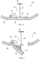
Figure 3 is a sectional view of the pressure relief arrangement ofFigure 2 in an open position. - With reference to
Figure 1 , a gas turbine engine is generally indicated at 10, having a principal androtational axis 11. Theengine 10 comprises, in axial flow series, anair intake 12, apropulsive fan 13, anintermediate pressure compressor 14, a high-pressure compressor 15,combustion equipment 16, a high-pressure turbine 17, anintermediate pressure turbine 18, a low-pressure turbine 19 and anexhaust nozzle 20. Anacelle 21 generally surrounds theengine 10 and defines both theintake 12 and theexhaust nozzle 20. - The
gas turbine engine 10 works in the conventional manner so that air entering theintake 12 is accelerated by thefan 13 to produce two air flows: a first air flow into theintermediate pressure compressor 14 and a second air flow which passes through abypass duct 22 to provide propulsive thrust. Theintermediate pressure compressor 14 compresses the air flow directed into it before delivering that air to thehigh pressure compressor 15 where further compression takes place. - The compressed air exhausted from the high-
pressure compressor 15 is directed into thecombustion equipment 16 where it is mixed with fuel and the mixture combusted. The resultant hot combustion products then expand through, and thereby drive the high, intermediate and low-pressure turbines nozzle 20 to provide additional propulsive thrust. The high 17, intermediate 18 and low 19 pressure turbines drive respectively thehigh pressure compressor 15,intermediate pressure compressor 14 andfan 13, each by suitable interconnecting shaft. - Other gas turbine engines to which the present disclosure may be applied may have alternative configurations. By way of example such engines may have an alternative number of interconnecting shafts (e.g. two) and/or an alternative number of compressors and/or turbines. Further the engine may comprise a gearbox provided in the drive train from a turbine to a compressor and/or fan.
- A pressure relief arrangement may be provided at location between the core and the bypass duct, the location of the pressure relief arrangement is indicated generally at 24 in
Figure 1 . In some embodiments, a pressure relief arrangement may be provided in a location indicated generally at 26. Often pressure relief arrangements are provided on the edge of ventilation zones to provide pressure relief in the event of a pipe or duct failure. - Referring to
Figures 2 and 3 , a pressure relief arrangement is indicated generally at 28. The pressure relief arrangement includes adoor 30 that is pivotably connected to acasing member 32 by ahinge 34. Thehinge 34 is connected at one end of thedoor 34. Thedoor 30 is also connected to amount 36 via anexpandable structure 38. In the present example, themount 36 is a core mount. Themount 36 is provided on a side of the door opposite to the direction in which the door pivots if opened. - The
expandable structure 38 includes anexpander 40 and acable 42. Thecable 42 is non-expandable and connects directly between the mount and theexpander 40. In the present example, theexpander 40 connects at a single point to thecable 42 and at multiple points or along a perimeter to thedoor 30. In the present example, the expander is connected over an area of the door that is approximately greater than 40% of the area of a surface of the door to which the expander is connected, for example greater than 50%, or greater than 60%. - The
expander 40 in the present example is made from a metallic material. However, in alternative embodiments the expander may be made from a metallic composite material. Depending on where the expander is to be used, the type of metal will be selected accordingly. However, in many cases, the metallic material will be selected so as to be capable of operation over a range of -30°C to over +300°C. - The expander is formed using holes, slots and/or folds so that it can move between a compact state (illustrated in
Figure 2 ) and an expanded state (illustrated inFigure 3 ). The expander may be a meshed structure. Alternatively, the expander may use geometric shapes and folds to enable it to move between the compact state and the expanded state. In exemplary embodiments, the expander may be designed using principles of metal origami, or pop-up structures. - The
door 30 is latched to thecasing 32 by alatch 44 provided at an opposite end of the door to thehinge 34. In the present example, thelatch 44 is configured such that when the pressure differential across the door reaches a certain level, the latch fails so the door can open. However, in alternative examples, a pressure sensor and control assembly may be provided to unlatch the door when a given pressure is detected. - Referring to
Figure 2 , during normal operation of the gas turbine engine, thedoor 30 is aligned with thecasing 32 and seals the gap provided therein (i.e. where the door is provided). Thelatch 44 is closed. Theexpander 40 is in a compact position, or, in other words, in a substantially 2D, or planar, configuration. Thecable 42 is extended, but in the present example is not under tension. - Referring to
Figure 3 , when the pressure on the radially inner side of the door (i.e. the side proximal to the mount 36) exceeds a certain level thelatch 44 fails. Thedoor 30 pivots about the hinged joint 34 to open. As the door opens, theexpander 40 moves from the compact state (shown inFigure 2 ) to the expanded state (shown inFigure 3 ), or, in other words, in a 3D, or volumetric, configuration. Thecable 42 is subject to tension, but does not substantially extend. - As the
door 30 hinges open, theexpander 40 may undergo a plastic deformation, such as to maintain the expanded state. In other words, once deployed, theexpander 40 will hold the door open and retain the expanded state. - The arrangement described above can have one or more of the following advantages compared to arrangements of the prior art:
- Reduction in part count because there is no need to have an articulated mechanism, such as a piston and cylinder arrangement
- Simplified manufacture
- Reduced possible failures in service
- Weight reduction
- Lower capital cost
- Increased control of door opening
- It will be understood that the invention is not limited to the embodiments above-described and various modifications and improvements can be made without departing from the concepts described herein. Except where mutually exclusive, any of the features may be employed separately or in combination with any other features and the disclosure extends to and includes all combinations and subcombinations of one or more features described herein.
Claims (15)
- A pressure relief arrangement (28) for a gas turbine engine (10), the arrangement comprising:a hinged door (30);a mount (36) spaced from the door (30); andan expandable structure (38) connected to the door (30) and to the mount (36) such that when the door (30) hinges open the expandable structure (38) expands.
- The arrangement according to the preceding claim, wherein the expandable structure (38) comprises an expander (40) configured such that the expander (40) can move between a first configuration and a second configuration, the second configuration having a greater volume than the first configuration.
- The arrangement according to the preceding claim, wherein the first configuration is a substantially planar configuration and the second configuration is a volumetric configuration.
- The arrangement according to the preceding claim, wherein the expander (40) is in the substantially planar configuration when the door (30) is closed, and wherein the expander (40) is in the volumetric configuration when the door (30) is open.
- The arrangement according to any one of claims 2 to 4, wherein the expander (40) comprises slots, holes and/or folds configured such that the expander (40) can move between the first configuration and the second configuration.
- The arrangement according to any one of claims 2 to 5, wherein the expander (40) comprises a pop-up structure configured to expand from the first configuration to the second configuration.
- The arrangement according to any one of claims 2 to 6, comprising a cable (42) that connects to the mount (36) and to the expander (40).
- The arrangement according to the preceding claim, wherein the expander (40) connects to the cable (42) at a single connection point.
- The arrangement according to any one of claims 2 to 8, wherein the expander (40) connects directly to the door (30).
- The arrangement according to any one of claims 2 to 9, wherein the expander (40) connects to the door (30) at a plurality of points, or along a perimeter of an area defined by the expander (40).
- The arrangement according to the preceding claim, wherein at the location of connection to the door (30), the area of the expander (40) is greater than 40% of the area of a surface of the door (30) to which the expander (40) is connected.
- The arrangement according to any one of claims 2 to 11, wherein the expander (40) undergoes a plastic deformation when passing from the first configuration to the second configuration.
- The arrangement according to any one of the previous claims, comprising a latch (44) configured to align one end of the door (30) with an adjacent component, wherein the latch (44) is configured to open when a pressure above a predetermined level is applied to the door (30).
- A gas turbine engine, comprising the arrangement (28) according to anyone of the previous claims.
- The gas turbine engine according to the preceding claim, comprising an engine core, and a casing member (32) surrounding the engine core, and wherein the mount (36) is provided radially internally of the casing member (32) and the door (30) is arranged to pivot outwardly away from the core.
Applications Claiming Priority (1)
| Application Number | Priority Date | Filing Date | Title |
|---|---|---|---|
| GBGB1704841.4A GB201704841D0 (en) | 2017-03-27 | 2017-03-27 | Gas Turbine Engine |
Publications (2)
| Publication Number | Publication Date |
|---|---|
| EP3382179A1 true EP3382179A1 (en) | 2018-10-03 |
| EP3382179B1 EP3382179B1 (en) | 2019-05-22 |
Family
ID=58687985
Family Applications (1)
| Application Number | Title | Priority Date | Filing Date |
|---|---|---|---|
| EP18159114.0A Active EP3382179B1 (en) | 2017-03-27 | 2018-02-28 | Gas turbine engine |
Country Status (3)
| Country | Link |
|---|---|
| US (1) | US10801363B2 (en) |
| EP (1) | EP3382179B1 (en) |
| GB (1) | GB201704841D0 (en) |
Cited By (1)
| Publication number | Priority date | Publication date | Assignee | Title |
|---|---|---|---|---|
| EP3470635A1 (en) * | 2017-10-12 | 2019-04-17 | Rolls-Royce plc | A pressure relief arrangement for a gas turbine engine |
Families Citing this family (2)
| Publication number | Priority date | Publication date | Assignee | Title |
|---|---|---|---|---|
| US12054256B2 (en) * | 2022-07-14 | 2024-08-06 | Wing Aviation, Llc | UAV with upper door including winch and method of operation |
| US12535032B2 (en) * | 2023-07-18 | 2026-01-27 | Airbus Operations Sas | Aircraft nacelle comprising a sealed box structure and a door which opens the box structure to the outside |
Citations (5)
| Publication number | Priority date | Publication date | Assignee | Title |
|---|---|---|---|---|
| US4825644A (en) * | 1987-11-12 | 1989-05-02 | United Technologies Corporation | Ventilation system for a nacelle |
| US20110171014A1 (en) * | 2007-08-20 | 2011-07-14 | Aircelle | Nacelle comprising at least one surge trap |
| US20110240137A1 (en) * | 2008-12-12 | 2011-10-06 | Aircelle | Overpressure hatch intended to be mounted on a wall of a turbojet engine nacelle |
| US20140069317A1 (en) * | 2012-09-13 | 2014-03-13 | Gm Global Technology Operation Llc | In-situ overheat alert for equipment |
| WO2015010271A1 (en) * | 2013-07-24 | 2015-01-29 | Mra Systems, Inc. | Engine door and latch assembly |
Family Cites Families (12)
| Publication number | Priority date | Publication date | Assignee | Title |
|---|---|---|---|---|
| US6059531A (en) * | 1998-06-19 | 2000-05-09 | Tai; Jen-Lung David | Impeller and fan blade attachment assembly |
| CA2472604A1 (en) * | 2002-01-09 | 2003-07-24 | The Nordam Group, Inc. | Variable area plug nozzle |
| DE102005063076A1 (en) * | 2005-12-29 | 2007-07-12 | Airbus Deutschland Gmbh | Extended decompression flap assembly |
| DE102008028799B4 (en) * | 2008-06-17 | 2015-07-02 | Airbus Operations Gmbh | Pressure equalizing valve for locating at an opening of a fuselage shell of an aircraft and fuselage part with such a pressure compensating valve |
| FR2953810B1 (en) * | 2009-12-16 | 2012-01-13 | Snecma | TURBOREACTOR NACELLE |
| US8839807B2 (en) * | 2010-10-08 | 2014-09-23 | The Boeing Company | Rapid response self-closing pressure equalization vent |
| CN203094456U (en) | 2012-11-28 | 2013-07-31 | 中国商用飞机有限责任公司 | A pressure release flap installation component for duct auxiliary structure |
| EP2743178B1 (en) * | 2012-12-11 | 2016-08-17 | AIRBUS HELICOPTERS DEUTSCHLAND GmbH | An air inlet combining a filter and a bypass device for use with a turbine engine |
| EP2921408B1 (en) * | 2014-03-21 | 2016-10-05 | Airbus Operations GmbH | Method and system for controlling the pressure in an aircraft cabin |
| US10060287B2 (en) * | 2015-07-09 | 2018-08-28 | Rohr, Inc | Pressure relief door assembly |
| US10935242B2 (en) * | 2016-07-07 | 2021-03-02 | General Electric Company | Combustor assembly for a turbine engine |
| GB201720831D0 (en) * | 2017-10-12 | 2018-01-31 | Rolls-Royce Ltd | A pressure relief arrangement for a gas turbine engine |
-
2017
- 2017-03-27 GB GBGB1704841.4A patent/GB201704841D0/en not_active Ceased
-
2018
- 2018-02-28 EP EP18159114.0A patent/EP3382179B1/en active Active
- 2018-03-26 US US15/935,795 patent/US10801363B2/en active Active
Patent Citations (5)
| Publication number | Priority date | Publication date | Assignee | Title |
|---|---|---|---|---|
| US4825644A (en) * | 1987-11-12 | 1989-05-02 | United Technologies Corporation | Ventilation system for a nacelle |
| US20110171014A1 (en) * | 2007-08-20 | 2011-07-14 | Aircelle | Nacelle comprising at least one surge trap |
| US20110240137A1 (en) * | 2008-12-12 | 2011-10-06 | Aircelle | Overpressure hatch intended to be mounted on a wall of a turbojet engine nacelle |
| US20140069317A1 (en) * | 2012-09-13 | 2014-03-13 | Gm Global Technology Operation Llc | In-situ overheat alert for equipment |
| WO2015010271A1 (en) * | 2013-07-24 | 2015-01-29 | Mra Systems, Inc. | Engine door and latch assembly |
Cited By (2)
| Publication number | Priority date | Publication date | Assignee | Title |
|---|---|---|---|---|
| EP3470635A1 (en) * | 2017-10-12 | 2019-04-17 | Rolls-Royce plc | A pressure relief arrangement for a gas turbine engine |
| US11028782B2 (en) | 2017-10-12 | 2021-06-08 | Rolls-Royce Plc | Pressure relief arrangement for a gas turbine engine |
Also Published As
| Publication number | Publication date |
|---|---|
| US20180274386A1 (en) | 2018-09-27 |
| US10801363B2 (en) | 2020-10-13 |
| GB201704841D0 (en) | 2017-05-10 |
| EP3382179B1 (en) | 2019-05-22 |
Similar Documents
| Publication | Publication Date | Title |
|---|---|---|
| US7540142B2 (en) | Multiple auxiliary power unit system inlet ducts controlled by a single actuator | |
| US8814462B2 (en) | Joint assembly | |
| EP3382179B1 (en) | Gas turbine engine | |
| EP2653699A2 (en) | Modular louver system | |
| EP3112605B1 (en) | Seals for gas turbine engine core nacelle cowlings | |
| US20190218978A1 (en) | Accessory gearbox assembly and a gas turbine engine comprising an accessory gearbox assembly | |
| GB2385382A (en) | A cowl structure for a gas turbine engine | |
| EP2725218A2 (en) | Aeroengine thrust reverser arrangement | |
| EP2865599A1 (en) | Auxiliary power unit inlet door having openings formed therein | |
| EP3163053A1 (en) | Bleed valve arrangement for a gas turbine engine | |
| US7717669B2 (en) | Load absorption arrangements for gas turbine engines | |
| EP3358149B1 (en) | Bleed valve with neutral or closing bias | |
| EP3736217B1 (en) | Pressure relief latch | |
| EP3816423B1 (en) | An exhaust nozzle for a gas turbine engine | |
| EP3708498B1 (en) | Seal arrangement | |
| US11028782B2 (en) | Pressure relief arrangement for a gas turbine engine | |
| US7182571B2 (en) | Variable stator vane actuating levers | |
| US10876428B2 (en) | Casing of a turbocharger and turbocharger | |
| US10859166B2 (en) | Gas turbine engine | |
| US20080252021A1 (en) | Seal arrangement | |
| EP3708484B1 (en) | Pressure relief door rotating exhaust deflector | |
| US12384549B2 (en) | Inner cowl arrangement for gas turbine engine | |
| US10968833B2 (en) | Accessory gearbox for a gas turbine engine |
Legal Events
| Date | Code | Title | Description |
|---|---|---|---|
| PUAI | Public reference made under article 153(3) epc to a published international application that has entered the european phase |
Free format text: ORIGINAL CODE: 0009012 |
|
| STAA | Information on the status of an ep patent application or granted ep patent |
Free format text: STATUS: THE APPLICATION HAS BEEN PUBLISHED |
|
| AK | Designated contracting states |
Kind code of ref document: A1 Designated state(s): AL AT BE BG CH CY CZ DE DK EE ES FI FR GB GR HR HU IE IS IT LI LT LU LV MC MK MT NL NO PL PT RO RS SE SI SK SM TR |
|
| AX | Request for extension of the european patent |
Extension state: BA ME |
|
| STAA | Information on the status of an ep patent application or granted ep patent |
Free format text: STATUS: REQUEST FOR EXAMINATION WAS MADE |
|
| 17P | Request for examination filed |
Effective date: 20181031 |
|
| RBV | Designated contracting states (corrected) |
Designated state(s): AL AT BE BG CH CY CZ DE DK EE ES FI FR GB GR HR HU IE IS IT LI LT LU LV MC MK MT NL NO PL PT RO RS SE SI SK SM TR |
|
| GRAP | Despatch of communication of intention to grant a patent |
Free format text: ORIGINAL CODE: EPIDOSNIGR1 |
|
| STAA | Information on the status of an ep patent application or granted ep patent |
Free format text: STATUS: GRANT OF PATENT IS INTENDED |
|
| INTG | Intention to grant announced |
Effective date: 20190301 |
|
| GRAS | Grant fee paid |
Free format text: ORIGINAL CODE: EPIDOSNIGR3 |
|
| GRAA | (expected) grant |
Free format text: ORIGINAL CODE: 0009210 |
|
| STAA | Information on the status of an ep patent application or granted ep patent |
Free format text: STATUS: THE PATENT HAS BEEN GRANTED |
|
| AK | Designated contracting states |
Kind code of ref document: B1 Designated state(s): AL AT BE BG CH CY CZ DE DK EE ES FI FR GB GR HR HU IE IS IT LI LT LU LV MC MK MT NL NO PL PT RO RS SE SI SK SM TR |
|
| REG | Reference to a national code |
Ref country code: GB Ref legal event code: FG4D |
|
| REG | Reference to a national code |
Ref country code: CH Ref legal event code: EP |
|
| REG | Reference to a national code |
Ref country code: IE Ref legal event code: FG4D |
|
| REG | Reference to a national code |
Ref country code: DE Ref legal event code: R096 Ref document number: 602018000097 Country of ref document: DE |
|
| REG | Reference to a national code |
Ref country code: AT Ref legal event code: REF Ref document number: 1136393 Country of ref document: AT Kind code of ref document: T Effective date: 20190615 |
|
| REG | Reference to a national code |
Ref country code: NL Ref legal event code: MP Effective date: 20190522 |
|
| REG | Reference to a national code |
Ref country code: LT Ref legal event code: MG4D |
|
| PG25 | Lapsed in a contracting state [announced via postgrant information from national office to epo] |
Ref country code: NL Free format text: LAPSE BECAUSE OF FAILURE TO SUBMIT A TRANSLATION OF THE DESCRIPTION OR TO PAY THE FEE WITHIN THE PRESCRIBED TIME-LIMIT Effective date: 20190522 Ref country code: SE Free format text: LAPSE BECAUSE OF FAILURE TO SUBMIT A TRANSLATION OF THE DESCRIPTION OR TO PAY THE FEE WITHIN THE PRESCRIBED TIME-LIMIT Effective date: 20190522 Ref country code: FI Free format text: LAPSE BECAUSE OF FAILURE TO SUBMIT A TRANSLATION OF THE DESCRIPTION OR TO PAY THE FEE WITHIN THE PRESCRIBED TIME-LIMIT Effective date: 20190522 Ref country code: HR Free format text: LAPSE BECAUSE OF FAILURE TO SUBMIT A TRANSLATION OF THE DESCRIPTION OR TO PAY THE FEE WITHIN THE PRESCRIBED TIME-LIMIT Effective date: 20190522 Ref country code: NO Free format text: LAPSE BECAUSE OF FAILURE TO SUBMIT A TRANSLATION OF THE DESCRIPTION OR TO PAY THE FEE WITHIN THE PRESCRIBED TIME-LIMIT Effective date: 20190822 Ref country code: PT Free format text: LAPSE BECAUSE OF FAILURE TO SUBMIT A TRANSLATION OF THE DESCRIPTION OR TO PAY THE FEE WITHIN THE PRESCRIBED TIME-LIMIT Effective date: 20190922 Ref country code: LT Free format text: LAPSE BECAUSE OF FAILURE TO SUBMIT A TRANSLATION OF THE DESCRIPTION OR TO PAY THE FEE WITHIN THE PRESCRIBED TIME-LIMIT Effective date: 20190522 Ref country code: AL Free format text: LAPSE BECAUSE OF FAILURE TO SUBMIT A TRANSLATION OF THE DESCRIPTION OR TO PAY THE FEE WITHIN THE PRESCRIBED TIME-LIMIT Effective date: 20190522 Ref country code: ES Free format text: LAPSE BECAUSE OF FAILURE TO SUBMIT A TRANSLATION OF THE DESCRIPTION OR TO PAY THE FEE WITHIN THE PRESCRIBED TIME-LIMIT Effective date: 20190522 |
|
| PG25 | Lapsed in a contracting state [announced via postgrant information from national office to epo] |
Ref country code: LV Free format text: LAPSE BECAUSE OF FAILURE TO SUBMIT A TRANSLATION OF THE DESCRIPTION OR TO PAY THE FEE WITHIN THE PRESCRIBED TIME-LIMIT Effective date: 20190522 Ref country code: GR Free format text: LAPSE BECAUSE OF FAILURE TO SUBMIT A TRANSLATION OF THE DESCRIPTION OR TO PAY THE FEE WITHIN THE PRESCRIBED TIME-LIMIT Effective date: 20190823 Ref country code: BG Free format text: LAPSE BECAUSE OF FAILURE TO SUBMIT A TRANSLATION OF THE DESCRIPTION OR TO PAY THE FEE WITHIN THE PRESCRIBED TIME-LIMIT Effective date: 20190822 Ref country code: RS Free format text: LAPSE BECAUSE OF FAILURE TO SUBMIT A TRANSLATION OF THE DESCRIPTION OR TO PAY THE FEE WITHIN THE PRESCRIBED TIME-LIMIT Effective date: 20190522 |
|
| REG | Reference to a national code |
Ref country code: AT Ref legal event code: MK05 Ref document number: 1136393 Country of ref document: AT Kind code of ref document: T Effective date: 20190522 |
|
| PG25 | Lapsed in a contracting state [announced via postgrant information from national office to epo] |
Ref country code: RO Free format text: LAPSE BECAUSE OF FAILURE TO SUBMIT A TRANSLATION OF THE DESCRIPTION OR TO PAY THE FEE WITHIN THE PRESCRIBED TIME-LIMIT Effective date: 20190522 Ref country code: CZ Free format text: LAPSE BECAUSE OF FAILURE TO SUBMIT A TRANSLATION OF THE DESCRIPTION OR TO PAY THE FEE WITHIN THE PRESCRIBED TIME-LIMIT Effective date: 20190522 Ref country code: SK Free format text: LAPSE BECAUSE OF FAILURE TO SUBMIT A TRANSLATION OF THE DESCRIPTION OR TO PAY THE FEE WITHIN THE PRESCRIBED TIME-LIMIT Effective date: 20190522 Ref country code: DK Free format text: LAPSE BECAUSE OF FAILURE TO SUBMIT A TRANSLATION OF THE DESCRIPTION OR TO PAY THE FEE WITHIN THE PRESCRIBED TIME-LIMIT Effective date: 20190522 Ref country code: EE Free format text: LAPSE BECAUSE OF FAILURE TO SUBMIT A TRANSLATION OF THE DESCRIPTION OR TO PAY THE FEE WITHIN THE PRESCRIBED TIME-LIMIT Effective date: 20190522 Ref country code: AT Free format text: LAPSE BECAUSE OF FAILURE TO SUBMIT A TRANSLATION OF THE DESCRIPTION OR TO PAY THE FEE WITHIN THE PRESCRIBED TIME-LIMIT Effective date: 20190522 |
|
| REG | Reference to a national code |
Ref country code: DE Ref legal event code: R097 Ref document number: 602018000097 Country of ref document: DE |
|
| RAP2 | Party data changed (patent owner data changed or rights of a patent transferred) |
Owner name: ROLLS-ROYCE PLC |
|
| PG25 | Lapsed in a contracting state [announced via postgrant information from national office to epo] |
Ref country code: IT Free format text: LAPSE BECAUSE OF FAILURE TO SUBMIT A TRANSLATION OF THE DESCRIPTION OR TO PAY THE FEE WITHIN THE PRESCRIBED TIME-LIMIT Effective date: 20190522 Ref country code: SM Free format text: LAPSE BECAUSE OF FAILURE TO SUBMIT A TRANSLATION OF THE DESCRIPTION OR TO PAY THE FEE WITHIN THE PRESCRIBED TIME-LIMIT Effective date: 20190522 |
|
| PLBE | No opposition filed within time limit |
Free format text: ORIGINAL CODE: 0009261 |
|
| STAA | Information on the status of an ep patent application or granted ep patent |
Free format text: STATUS: NO OPPOSITION FILED WITHIN TIME LIMIT |
|
| PG25 | Lapsed in a contracting state [announced via postgrant information from national office to epo] |
Ref country code: TR Free format text: LAPSE BECAUSE OF FAILURE TO SUBMIT A TRANSLATION OF THE DESCRIPTION OR TO PAY THE FEE WITHIN THE PRESCRIBED TIME-LIMIT Effective date: 20190522 |
|
| 26N | No opposition filed |
Effective date: 20200225 |
|
| PG25 | Lapsed in a contracting state [announced via postgrant information from national office to epo] |
Ref country code: PL Free format text: LAPSE BECAUSE OF FAILURE TO SUBMIT A TRANSLATION OF THE DESCRIPTION OR TO PAY THE FEE WITHIN THE PRESCRIBED TIME-LIMIT Effective date: 20190522 |
|
| REG | Reference to a national code |
Ref country code: BE Ref legal event code: MM Effective date: 20200229 |
|
| PG25 | Lapsed in a contracting state [announced via postgrant information from national office to epo] |
Ref country code: MC Free format text: LAPSE BECAUSE OF FAILURE TO SUBMIT A TRANSLATION OF THE DESCRIPTION OR TO PAY THE FEE WITHIN THE PRESCRIBED TIME-LIMIT Effective date: 20190522 Ref country code: LU Free format text: LAPSE BECAUSE OF NON-PAYMENT OF DUE FEES Effective date: 20200228 |
|
| PG25 | Lapsed in a contracting state [announced via postgrant information from national office to epo] |
Ref country code: IE Free format text: LAPSE BECAUSE OF NON-PAYMENT OF DUE FEES Effective date: 20200228 |
|
| PG25 | Lapsed in a contracting state [announced via postgrant information from national office to epo] |
Ref country code: BE Free format text: LAPSE BECAUSE OF NON-PAYMENT OF DUE FEES Effective date: 20200229 |
|
| PG25 | Lapsed in a contracting state [announced via postgrant information from national office to epo] |
Ref country code: LI Free format text: LAPSE BECAUSE OF NON-PAYMENT OF DUE FEES Effective date: 20210228 Ref country code: CH Free format text: LAPSE BECAUSE OF NON-PAYMENT OF DUE FEES Effective date: 20210228 |
|
| PG25 | Lapsed in a contracting state [announced via postgrant information from national office to epo] |
Ref country code: MT Free format text: LAPSE BECAUSE OF FAILURE TO SUBMIT A TRANSLATION OF THE DESCRIPTION OR TO PAY THE FEE WITHIN THE PRESCRIBED TIME-LIMIT Effective date: 20190522 Ref country code: CY Free format text: LAPSE BECAUSE OF FAILURE TO SUBMIT A TRANSLATION OF THE DESCRIPTION OR TO PAY THE FEE WITHIN THE PRESCRIBED TIME-LIMIT Effective date: 20190522 |
|
| PG25 | Lapsed in a contracting state [announced via postgrant information from national office to epo] |
Ref country code: MK Free format text: LAPSE BECAUSE OF FAILURE TO SUBMIT A TRANSLATION OF THE DESCRIPTION OR TO PAY THE FEE WITHIN THE PRESCRIBED TIME-LIMIT Effective date: 20190522 Ref country code: IS Free format text: LAPSE BECAUSE OF FAILURE TO SUBMIT A TRANSLATION OF THE DESCRIPTION OR TO PAY THE FEE WITHIN THE PRESCRIBED TIME-LIMIT Effective date: 20190922 |
|
| P01 | Opt-out of the competence of the unified patent court (upc) registered |
Effective date: 20230528 |
|
| PG25 | Lapsed in a contracting state [announced via postgrant information from national office to epo] |
Ref country code: SI Free format text: LAPSE BECAUSE OF FAILURE TO SUBMIT A TRANSLATION OF THE DESCRIPTION OR TO PAY THE FEE WITHIN THE PRESCRIBED TIME-LIMIT Effective date: 20190522 |
|
| PGFP | Annual fee paid to national office [announced via postgrant information from national office to epo] |
Ref country code: GB Payment date: 20260223 Year of fee payment: 9 |
|
| PGFP | Annual fee paid to national office [announced via postgrant information from national office to epo] |
Ref country code: DE Payment date: 20260220 Year of fee payment: 9 |
|
| PGFP | Annual fee paid to national office [announced via postgrant information from national office to epo] |
Ref country code: FR Payment date: 20260224 Year of fee payment: 9 |