EP3382108A1 - Device for reducing impact during traveling of construction machine and method for controlling construction machine using same - Google Patents
Device for reducing impact during traveling of construction machine and method for controlling construction machine using same Download PDFInfo
- Publication number
- EP3382108A1 EP3382108A1 EP16876075.9A EP16876075A EP3382108A1 EP 3382108 A1 EP3382108 A1 EP 3382108A1 EP 16876075 A EP16876075 A EP 16876075A EP 3382108 A1 EP3382108 A1 EP 3382108A1
- Authority
- EP
- European Patent Office
- Prior art keywords
- pressure
- travel
- construction machinery
- pilot
- hydraulic pump
- Prior art date
- Legal status (The legal status is an assumption and is not a legal conclusion. Google has not performed a legal analysis and makes no representation as to the accuracy of the status listed.)
- Granted
Links
- 238000010276 construction Methods 0.000 title claims abstract description 68
- 238000000034 method Methods 0.000 title description 11
- 239000010720 hydraulic oil Substances 0.000 claims abstract description 48
- 230000035939 shock Effects 0.000 claims abstract description 46
- 238000006073 displacement reaction Methods 0.000 claims description 4
- 239000003921 oil Substances 0.000 description 11
- 230000003247 decreasing effect Effects 0.000 description 7
- 238000010586 diagram Methods 0.000 description 6
- 230000003252 repetitive effect Effects 0.000 description 4
- 230000005540 biological transmission Effects 0.000 description 3
- 230000000694 effects Effects 0.000 description 2
- 230000001133 acceleration Effects 0.000 description 1
- 239000000463 material Substances 0.000 description 1
- 230000002441 reversible effect Effects 0.000 description 1
Images


Classifications
-
- E—FIXED CONSTRUCTIONS
- E02—HYDRAULIC ENGINEERING; FOUNDATIONS; SOIL SHIFTING
- E02F—DREDGING; SOIL-SHIFTING
- E02F9/00—Component parts of dredgers or soil-shifting machines, not restricted to one of the kinds covered by groups E02F3/00 - E02F7/00
- E02F9/20—Drives; Control devices
- E02F9/22—Hydraulic or pneumatic drives
- E02F9/2221—Control of flow rate; Load sensing arrangements
- E02F9/2225—Control of flow rate; Load sensing arrangements using pressure-compensating valves
- E02F9/2228—Control of flow rate; Load sensing arrangements using pressure-compensating valves including an electronic controller
-
- E—FIXED CONSTRUCTIONS
- E02—HYDRAULIC ENGINEERING; FOUNDATIONS; SOIL SHIFTING
- E02F—DREDGING; SOIL-SHIFTING
- E02F9/00—Component parts of dredgers or soil-shifting machines, not restricted to one of the kinds covered by groups E02F3/00 - E02F7/00
- E02F9/20—Drives; Control devices
- E02F9/22—Hydraulic or pneumatic drives
- E02F9/2221—Control of flow rate; Load sensing arrangements
- E02F9/2232—Control of flow rate; Load sensing arrangements using one or more variable displacement pumps
- E02F9/2235—Control of flow rate; Load sensing arrangements using one or more variable displacement pumps including an electronic controller
-
- E—FIXED CONSTRUCTIONS
- E02—HYDRAULIC ENGINEERING; FOUNDATIONS; SOIL SHIFTING
- E02F—DREDGING; SOIL-SHIFTING
- E02F9/00—Component parts of dredgers or soil-shifting machines, not restricted to one of the kinds covered by groups E02F3/00 - E02F7/00
- E02F9/20—Drives; Control devices
- E02F9/22—Hydraulic or pneumatic drives
- E02F9/2253—Controlling the travelling speed of vehicles, e.g. adjusting travelling speed according to implement loads, control of hydrostatic transmission
-
- E—FIXED CONSTRUCTIONS
- E02—HYDRAULIC ENGINEERING; FOUNDATIONS; SOIL SHIFTING
- E02F—DREDGING; SOIL-SHIFTING
- E02F9/00—Component parts of dredgers or soil-shifting machines, not restricted to one of the kinds covered by groups E02F3/00 - E02F7/00
- E02F9/20—Drives; Control devices
- E02F9/22—Hydraulic or pneumatic drives
- E02F9/226—Safety arrangements, e.g. hydraulic driven fans, preventing cavitation, leakage, overheating
-
- E—FIXED CONSTRUCTIONS
- E02—HYDRAULIC ENGINEERING; FOUNDATIONS; SOIL SHIFTING
- E02F—DREDGING; SOIL-SHIFTING
- E02F9/00—Component parts of dredgers or soil-shifting machines, not restricted to one of the kinds covered by groups E02F3/00 - E02F7/00
- E02F9/20—Drives; Control devices
- E02F9/22—Hydraulic or pneumatic drives
- E02F9/2278—Hydraulic circuits
- E02F9/2285—Pilot-operated systems
-
- E—FIXED CONSTRUCTIONS
- E02—HYDRAULIC ENGINEERING; FOUNDATIONS; SOIL SHIFTING
- E02F—DREDGING; SOIL-SHIFTING
- E02F9/00—Component parts of dredgers or soil-shifting machines, not restricted to one of the kinds covered by groups E02F3/00 - E02F7/00
- E02F9/20—Drives; Control devices
- E02F9/22—Hydraulic or pneumatic drives
- E02F9/2278—Hydraulic circuits
- E02F9/2296—Systems with a variable displacement pump
Definitions
- the present invention relates to a travelling shock reducing device for construction machinery and a control method for construction machinery using the same, more particularly, to a travelling shock reducing device for construction machinery configured to control an amount of a hydraulic oil discharged from a hydraulic pump and a control method for construction machinery using the same.
- Construction machinery for example, wheel type excavator may travel forward and backward using a hydraulic oil discharged from a hydraulic pump.
- an amount of the hydraulic oil discharged from the hydraulic pump may be controlled by a manipulation amount of a travel pedal.
- the amount of the hydraulic oil discharged from the hydraulic pump may be increased rapidly.
- a travel speed may be increased rapidly thereby causing a shock on the driver.
- An object of the present invention provides a travelling shock reducing device for construction machinery.
- Another object of the present invention provides a control method for construction machinery using the above travelling shock reducing device.
- a travelling shock reducing device for construction machinery includes a travel manipulation portion to generate a pilot pressure for controlling an amount of a hydraulic oil discharged from a hydraulic pump to be supplied to a travel motor of the construction machinery, a sensing portion configured to detect a manipulation change of the travel manipulation portion, a pressure reducing valve installed between the travel manipulation portion and the hydraulic pump to control the pilot pressure supplied to the hydraulic pump, and a controller receiving information on the manipulation change from the sensing portion, and configured to control an operation of the pressure reducing valve such that the pilot pressure is gently increased when the manipulation change is greater than a predetermined value.
- a magnitude of the pilot pump generated by the travel manipulation portion when a magnitude of the pilot pump generated by the travel manipulation portion is increased in a first ratio, a magnitude of the pilot pump supplied from the pressure reducing valve to the hydraulic pump may be increased in a second ratio less than the first ratio.
- the travel manipulation portion may include a travel pedal.
- the travelling shock reducing device for construction machinery may further include an angle sensor configured to detect an angle change of the travel pedal.
- the sensing portion may include a pressure sensor configured to detect a change in the pilot pressure.
- the pressure sensor may include a pressure switch.
- the pressure reducing valve may include electronic proportional pressure reducing (EPPR) valve.
- EPPR electronic proportional pressure reducing
- the pressure reducing valve may control such that a magnitude of the second pilot pressure is in proportion to a control signal received from the controller.
- the pressure reducing valve may control such that a magnitude of the second pilot pressure is in inverse proportion to a control signal received from the controller.
- the travelling shock reducing device for construction machinery may further include a regulator installed between the pressure reducing valve and the hydraulic pump.
- the hydraulic pump may be a variable displacement hydraulic pump.
- the travelling shock reducing device for construction machinery may further include a wok manipulation portion to generate a third pilot pressure for controlling an amount of the hydraulic oil discharged from the hydraulic pump to be supplied to an actuator of the construction machinery, and a shuttle valve configured to select and output a higher pressure of the pilot pressure controlled by the pressure reducing valve and the third pilot pressure generated by the work manipulation portion.
- the pressure reducing valve may be installed in a pilot line that connects the travel manipulation portion and the shuttle valve.
- a travelling shock reducing device for construction machinery may control to gently increase an amount of a hydraulic oil supplied to a travel motor even when a driver manipulates quickly a travel manipulation portion.
- a shock caused by the driver's quick manipulation during travel may be reduced.
- Example embodiments will be described more fully hereinafter with reference to the accompanying drawings, in which example embodiments are shown.
- Example embodiments may, however, be embodied in many different forms and should not be construed as limited to example embodiments set forth herein. Rather, these example embodiments are provided so that this disclosure will be thorough and complete, and will fully convey the scope of example embodiments to those skilled in the art.
- the sizes and relative sizes of components or elements may be exaggerated for clarity.
- first, second, third, etc. may be used herein to describe various elements, components, regions, layers and/or sections, these elements, components, regions, layers and/or sections should not be limited by these terms. These terms are only used to distinguish one element, component, region, layer or section from another element, component, region, layer or section. Thus, a first element, component, region, layer or section discussed below could be termed a second element, component, region, layer or section without departing from the teachings of example embodiments.
- spatially relative terms such as “beneath,” “below,” “lower,” “above,” “upper” and the like, may be used herein for ease of description to describe one element or feature's relationship to another element(s) or feature(s) as illustrated in the figures. It will be understood that the spatially relative terms are intended to encompass different orientations of the device in use or operation in addition to the orientation depicted in the figures. For example, if the device in the figures is turned over, elements described as “below” or “beneath” other elements or features would then be oriented “above” the other elements or features. Thus, the exemplary term “below” can encompass both an orientation of above and below. The device may be otherwise oriented (rotated 90 degrees or at other orientations) and the spatially relative descriptors used herein interpreted accordingly.
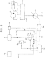
- FIG. 1 is a hydraulic circuit diagram illustrating a travel system for construction machinery in accordance with example embodiments.
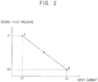
- FIG. 2 is a graph illustrating operating characteristics of a pressure reducing valve in FIG. 1 .
- a travel system for construction machinery may include a hydraulic pump 10, a travel motor 20 receiving a hydraulic oil discharged from the hydraulic pump 10 to travel the construction machinery, a main control valve 30 configured to control a direction of the hydraulic oil supplied to the travel motor 20, a travel manipulation portion 40 to generate a pilot pressure for controlling the hydraulic pump 10 in response to a manipulation of a driver, and a travelling shock reducing device configured to reduce shock caused by driver's quick handling for travel.
- the construction machinery may include a wheel excavator, a wheel loader, a forklift, etc.
- a case that the construction machinery includes a wheel type excavator will be explained for convenience of explanation.
- the travelling shock reducing device according to the inventive concept may be applied not be limited to control only the wheel excavator, and may be applied to the wheel loader, the forklift, etc.
- the hydraulic pump 10 may be connected to an output shaft of an engine. As the output shaft rotates, the hydraulic pump 10 may be driven to discharge the hydraulic oil.
- the hydraulic oil may be stored in an oil tank T, and the hydraulic oil discharged from the hydraulic pump 10 may be supplied to the travel motor 20, a swing motor and actuators through the main control valve 30. And then, the supplied hydraulic oil may be drained to the oil tank T.
- the actuators may include a hydraulic cylinder for driving a work apparatus such as a boom, an arm, a bucket, etc.
- the hydraulic pump 10 may be a variable displacement hydraulic pump.
- the variable displacement hydraulic pump may be a swash plate type axial piston pump.
- the swash plate may be a disk installed at an oblique angle with respect to a rotating axis of the hydraulic pump 10.
- An amount of the hydraulic oil discharged from the hydraulic pump 10 may be changed according to the oblique angle with respect to the rotating axis. That is, by varying the angle of the swash plate, the amount of the hydraulic oil discharged from the hydraulic pump 10 may be adjusted.
- the angle of the swash plate is increased, the amount of the hydraulic oil discharged from the hydraulic pump 10 may be increased, while as the angle of the swash plate is decreased, the amount of the hydraulic oil discharged from the hydraulic pump 10 may be decreased.
- the hydraulic motor 20 may receive the hydraulic oil from the hydraulic pump 10 to generate a travel driving force.
- the travel driving force may be transferred to a driving axle via a transmission connected to the hydraulic motor 20.
- the construction machine may travel forward and backward.
- the main control valve 30 may receive the hydraulic oil from the hydraulic pump 10 to control a pressure, an amount, a direction, etc of the hydraulic oil supplied to the travel motor 20.
- the main control valve may control the direction of the hydraulic oil supplied to the travel motor such that the construction machinery may travel forward or backward according to the direction of the supplied hydraulic oil and perform various works using the work apparatus.
- FIG. 1 One hydraulic pump 10 and one travel motor 20 connected by the main control valve 30 are illustrated in FIG. 1 , however, it may not be limited thereto.
- the main control valve may be connected to a plurality of hydraulic motors, and the main control valve may control an amount of the hydraulic oil supplied to the swing motor and the actuators.
- the travel manipulation portion 40 may be installed in a cabin of the construction machinery, and may generate a pilot pressure corresponding to the manipulation of a driver.
- the pilot pressure may be supplied to the hydraulic pump 10 to control the angle of the swash plate, or may be supplied to the main control valve 30 to control the amount of the hydraulic oil supplied to the travel motor 20.
- the travel manipulation portion may be a travel pedal.
- the construction machinery may include a pilot pump (not illustrated) which supplies a control oil for controlling the swash plate and/or the main control valve 30.
- the control oil may include a material substantially the same as the hydraulic oil.
- the pilot pump may be connected to the output shaft of the engine, and as the output shaft rotates, the pilot pump may be driven to discharge the control oil.
- the discharged control oil may have a pilot pressure corresponding to the manipulation of a driver.
- the travel manipulation portion 40 may generate a pilot pressure corresponding to the manipulation signal.
- the pilot pressure may be supplied to the hydraulic pump 10 through a pilot line 50, to thereby control the angle of the swash angle.
- the pilot line 50 may include a first pilot line 52 and a second pilot line 54.
- the first pilot line 52 may be a pilot line between the travel manipulation portion 40 and a below mentioned pressure reducing valve 120
- the second pilot line 54 may be a pilot line between the pressure reducing valve 120 and the hydraulic pump 10.
- a pressure of the control oil flowing through the first pilot line 52 may be referred to as a first pilot pressure, and a pressure of the control oil flowing through the second pilot line 54.
- the first pilot pressure may be the pilot pressure corresponding to the manipulation signal of a driver
- the second pilot pressure may be a pilot pressure of the control oil supplied to the hydraulic pump 10 for controlling the angle of the swash plate.
- the travelling shock reducing device may further include a regulator 140 installed in the pilot line 50.
- the regulator 140 may control to maintain an amount and a pressure of the hydraulic oil discharged from the hydraulic pump 10 constantly regardless of load.
- the travelling shock reducing device may include a pressure sensor 100 configured to detect the pilot pressure generated by the travel manipulation portion 40, an angle sensor 110 configured to detect a manipulation amount of the manipulation portion 40, a controller 130 configured to receive information detected from the sensors 100, 110 and to generate a control signal for controlling the pilot pressure, and the pressure reducing valve 120 configured to control a magnitude of the pilot pressure according to the control signal.
- the pressure sensor 100 may be installed in the first pilot line 52, and may detect the magnitude of the first pilot pressure.
- the detected pressure information may be transmitted to the controller 130 through wireless transmission, for example, CAN (controller area network), LIN (local interconnect network), FlexRay, etc.
- the pressure sensor may be connected to the controller 130 through a wire.
- the pressure sensor may be a pressure switch.
- the pressure switch may compare the pressure of the first pilot line 52 with a predetermined pressure to be turned ON or OFF. That is, when the first pilot pressure is greater than or identical to the predetermined pressure, the pressure switch may be turned ON and the pressure information may be transmitted to the controller 130.
- the pressure sensor 100 may transmit the first pilot pressure to the controller 130 constantly or periodically.
- the angle sensor 110 may be installed in the travel manipulation portion 40, and may detect a manipulation amount of the travel manipulation portion 40.
- the angle sensor may detect a change in an inclination angle of the travel manipulation portion with respect to a gravitational direction, or a change in a relative position between the travel manipulation portion and a bottom surface of the cabin.
- the detected angle information may be transmitted to the controller 130 through wireless transmission, for example, CAN (controller area network), LIN (local interconnect network), FlexRay, etc.
- the angle pressure sensor may be connected to the controller 130 through a wire.
- the travelling shock reducing device may include the pressure sensor 100 and may not include the angle sensor 110.
- the travelling shock reducing device may include the angle sensor 110 and may not include the pressure sensor 100.
- the pressure of the control oil flowing through the first pilot line 52 may be determined by the manipulation amount of a driver.
- the manipulation amount may be in proportion to the extent that the driver manipulates the travel manipulation portion 40.
- the angle of the travel manipulation portion 40 detected by the angle sensor 110 and the first pilot pressure detected by the pressure sensor 100 may be converted to each other.
- the travelling shock reducing device may include any one selected from the pressure sensor 100 and the angle sensor 110.
- the pressure reducing valve 120 may be installed in the pilot line 50, and may receive the control signal from the controller 130.
- the pressure reducing valve 120 may control the magnitude of the second pilot pressure supplied to the hydraulic pump 10 corresponding the received control signal.
- the pressure reducing valve may include electronic proportional pressure reducing (EPPR) valve.
- the electronic proportional pressure reducing valve may generate a pilot pressure corresponding to the magnitude of the received control signal, for example, the magnitude of current. That is, the magnitude of the second pilot pressure may be determined according to the magnitude of the control signal received from the controller 130.
- the pressure reducing valve 120 may control such that the magnitude of the second pilot pressure may be in inverse proportion to the control signal received from the controller 130.
- the magnitude of the second pilot pressure may be a first pressure P1 (point A).
- the magnitude of the second pilot pressure may be a second pressure P2 (point B).
- the second current C2 may be greater than the first current C1
- the first pressure P1 may be greater than the second pressure P2. That is, the greater the magnitude of the control signal inputted to the pressure reducing valve 120 is, the less the magnitude of the second pilot pressure outputted through the second pilot line 54 is.
- the controller 130 may receive the information on the pressure of the first pilot line 52 and the information on the manipulation amount of the travel manipulation portion 40 from the pressure sensor 100 and the angle sensor 110. The controller 130 may determine whether or not the driver manipulates quickly the travel manipulation portion 40, based on the received information. When it is determined that the driver manipulates quickly the travel manipulation portion 40, the control signal may be outputted to the pressure reducing valve 120 to control such that the second pilot pressure may be increased gently. When the second pilot pressure is increased gently, the angle of the swash plate of the hydraulic pump 10 may be increased gently, and accordingly, the amount of the hydraulic oil supplied to the travel motor 20 may be increased gently. Thus, the travelling shock caused by the driver's quick manipulation may be reduced.
- the controller may be an electronic control unit (ECU).
- the travelling shock reducing device for construction machinery may control to gently increase the amount of the hydraulic oil supplied to the travel motor 20 even when the driver manipulates quickly the travel manipulation portion 40.
- FIG. 3 is a flow chart illustrating a method of controlling construction machinery using the travel system in FIG. 1 .
- FIG. 4 is graphs illustrating changes in a pilot pressure and an input current.
- manipulation information on a travel manipulation portion may be obtained (S100).
- a first pilot pressure may be generated in a first pilot line 52 corresponding to the manipulation amount.
- a controller 130 may receive information on the first pilot pressure from a pressure sensor 100 installed in the first pilot line 52.
- the controller 130 may receive information on an angle of the travel manipulation portion 40 from an angle sensor installed in the travel manipulation portion 40.
- the controller 130 may determine a manipulation state of the travel manipulation portion 40 using the received pressure information or angle information.
- the travel manipulation portion may be a travel pedal.
- the controller 130 may determine that the driver has manipulated quickly the travel manipulation portion 40.
- the predetermined pressure may be set in consideration of dimensions of the construction machinery, kinds of a selected change gear step, working conditions, etc.
- the controller 130 may determine that the driver has manipulated quickly the travel manipulation portion 40.
- the predetermined pressure may be set in consideration of dimensions of the construction machinery, kinds of a selected change gear step, working conditions, etc.
- an amount of a hydraulic oil discharged from a hydraulic motor may be controlled to be increased gently (S120).
- the controller 130 may control such that an angle of a swash angle of the hydraulic pump 10 may be increased gently. Thus, a rapid increase in the amount of the hydraulic oil discharged from the hydraulic pump 10 may be prevented, to thereby suppress the travelling shock.
- a first pilot pressure may be generated in the first pilot line 52 corresponding to the manipulation amount.
- the pressure sensor 100 may detect and provide the first pilot pressure to the controller 130.
- the controller 130 may compare the first pilot pressure with the predetermined pressure to determine whether or not the driver manipulates quickly the travel manipulation portion 40.
- the controller 130 may increase the magnitude of the current inputted to the pressure reducing valve 120.
- the pressure reducing valve 120 may be switched to the right direction.
- the pilot pressure supplied to the swash plate that is, the second pilot pressure may be decreased to be less than the first pilot pressure.
- the controller 130 may decrease the magnitude of the input current gently.
- the second pilot pressure may be increased gently until the second pilot pressure reaches the magnitude of the first pilot pressure, and accordingly, the amount of the hydraulic oil discharged from the hydraulic pump 10 may be increased gently.
- the process of controlling the pilot pressure by the controller 130 is illustrated in FIG. 4 .
- the first and second pilot pressures may be zero, and the current inputted to the pressure reducing valve 120 may be a minimum value.
- the first pilot pressure may be increased quickly corresponding to the manipulation amount of the travel manipulation portion 40.
- the controller 130 may increase quickly the current inputted to the pressure reducing valve 120.
- the increase in the second pilot pressure may not be relatively large.
- the controller 120 may decrease gently the magnitude of the current inputted to the pressure reducing valve 120.
- the second pilot pressure may be increased gently until the second pilot pressure reaches the magnitude of the first pilot pressure (third zone, III).
- a decreasing rate of the input current and an increasing rate of the second pilot pressure may be set in consideration of dimensions of the construction machinery, kinds of a selected change gear step, working conditions, etc.
- the input current is decreased in a linear fashion, however, it may not be limited thereto.
- the input current may be decreased in a parabolic fashion, or decreased in stages.
- the amount of the hydraulic oil supplied to the travel motor 20 may be increased gently.
- the travelling shock may be prevented to thereby provide smooth travel.
- FIG. 5 is a hydraulic circuit diagram illustrating a travel system for construction machinery in accordance with example embodiments.
- FIG. 6 is a graph illustrating operating characteristics of a pressure reducing valve in FIG. 5 .
- the hydraulic system for construction machinery may be substantially the same as or similar to the travel system for construction machinery as described with reference to FIG. 1 , except a pressure reducing valve 122.
- same reference numerals will be used to refer to the same or like elements and any further repetitive explanation concerning the above elements will be omitted.
- a travel system for construction machinery may include a hydraulic pump 10 to discharge a hydraulic oil, a travel motor 20 receiving the hydraulic oil to travel the construction machinery, a main control valve 30 configured to control the hydraulic oil supplied to the travel motor 20, a travel manipulation portion 40 to generate a pilot pressure for controlling an amount of the hydraulic oil discharged from the hydraulic pump 10 in response to a manipulation of a driver, and a travelling shock reducing device configured to reduce shock caused by driver's quick handling for travel.
- the travelling shock reducing device may include a pressure sensor 100 configured to detect the pilot pressure generated by the travel manipulation portion 40, an angle sensor 110 configured to detect a manipulation amount of the manipulation portion 40, a controller 130 configured to receive information detected from the sensors 100, 110 and to generate a control signal for controlling the pilot pressure, and a pressure reducing valve 122 configured to control a magnitude of the pilot pressure according to the control signal.
- the pressure reducing valve 122 may be installed in a pilot line 50, and may receive the control signal from the controller 130.
- the pressure reducing valve 122 may control the magnitude of a second pilot pressure supplied to the hydraulic pump 10 corresponding the received control signal.
- the pressure reducing valve may include electronic proportional pressure reducing (EPPR) valve.
- the electronic proportional pressure reducing valve may generate a pilot pressure corresponding to the magnitude of the received control signal, for example, the magnitude of current. That is, the magnitude of the second pilot pressure may be determined according to the magnitude of the control signal received from the controller 130.
- the pressure reducing valve 122 may control such that the magnitude of the second pilot pressure may be in proportion to the control signal received from the controller 130.
- the magnitude of the second pilot pressure may be a third pressure P3 (point D).
- the magnitude of the second pilot pressure may be a fourth pressure P4 (point E).
- the fourth current C4 may be greater than the third current C3, and the fourth pressure P4 may be greater than the third pressure P3. That is, the greater the magnitude of the control signal inputted to the pressure reducing valve 122 is, the greater the magnitude of the second pilot pressure outputted through the second pilot line 54 is.
- the travelling shock reducing device for construction machinery may control to gently increase the amount of the hydraulic oil supplied to the travel motor 20 even when the driver manipulates quickly the travel manipulation portion 40.
- FIG. 7 is graphs illustrating changes in a pilot pressure and an input current.
- the control method of FIG. 7 may be substantially the same as or similar to the control method for construction machinery as described with reference to FIGS. 3 and 4 , except changes in a second pilot pressure and an input current.
- same reference numerals will be used to refer to the same or like elements and any further repetitive explanation concerning the above elements will be omitted.
- the first and second pilot pressures may be zero, and the current inputted to the pressure reducing valve 122 may be a minimum value.
- the first pilot pressure may be increased quickly corresponding to the manipulation amount of the travel manipulation portion 40.
- the controller 130 may increase gently the current inputted to the pressure reducing valve 122.
- the second pilot pressure may be increased gently.
- the controller 130 may increase gently the magnitude of the current inputted to the pressure reducing valve 122.
- the second pilot pressure may be increased gently until the second pilot pressure reaches the magnitude of the first pilot pressure (sixth zone, VI).
- an increasing rate of the input current and an increasing rate of the second pilot pressure may be set in consideration of dimensions of the construction machinery, kinds of a selected change gear step, working conditions, etc.
- the input current is increased in a linear fashion, however, it may not be limited thereto.
- the input current may be increased in a parabolic fashion, or increased in stages.
- the amount of the hydraulic oil supplied to the travel motor 20 may be increased gently.
- the travelling shock may be prevented to thereby provide smooth travel.
- FIG. 8 is a hydraulic circuit diagram illustrating a hydraulic system for construction machinery in accordance with example embodiments.
- the hydraulic system for construction machinery may be substantially the same as or similar to the hydraulic system for construction machinery as described with reference to FIG. 1 , except a work manipulation portion and a shuttle valve.
- same reference numerals will be used to refer to the same or like elements and any further repetitive explanation concerning the above elements will be omitted.
- a hydraulic system for construction machinery may include a hydraulic pump 10 to discharge a hydraulic oil, a travel motor 20 receiving the hydraulic oil to travel the construction machinery, an actuator 22 receiving the hydraulic oil to drive a work apparatus of the construction machinery, a travel manipulation portion 40 and a wok manipulation portion 42 to generate a pilot pressure for controlling an amount of the hydraulic oil discharged from the hydraulic pump 10 in response to a manipulation of a driver, and a travelling shock reducing device configured to reduce shock caused by driver's quick operation of the travel manipulation portion 40.
- the travel manipulation portion 40 may generate a first pilot pressure for controlling an amount of the hydraulic oil supplied to the travel motor 20.
- the travel manipulation portion 40 may include a travel pedal.
- the travel manipulation portion 40 may generate a third pilot pressure for controlling an amount of the hydraulic oil supplied to the actuator 22 for driving the work apparatus.
- the work manipulation portion 42 may include a joystick.
- the actuator 22 may include a swing motor, a boom cylinder, an arm cylinder, a bucket cylinder, etc.
- the first pilot pressure generated from the travel manipulation portion 40 may be supplied to the hydraulic pump 10 through a pilot line 50.
- the third pilot pressure generated from the work manipulation portion 42 may be supplied to the hydraulic pump 10 through a third pilot line 60.
- the hydraulic system may further include a shuttle valve 150 which selects and outputs a higher pressure of two pressures inputted through an outlet portion.
- First and second end portions of an inlet of the shuttle valve may be connected to the pilot line 50 and the third pilot line 60 respectively.
- the pilot line 50 may include a first pilot line 52 and a second pilot line 54.
- the first pilot line 52 may connect the travel manipulation portion 40 and a pressure reducing valve 120
- the second pilot line 54 may connect the pressure reducing valve 120 and the first end portion of the inlet of the shuttle valve 150.
- the third pilot line 60 may connect the work manipulation portion 42 and the second end portion of the inlet of the shuttle valve 150.
- a fourth pilot line 70 may connect the outlet of the shuttle valve 150 and a regulator 140.
- the shuttle valve 150 may select a higher pressure of a second pilot pressure adjusted by the pressure reducing valve 120 and the third pilot pressure generated by the work manipulation portion 42 and output to a regulator 140.
Abstract
Description
- The present invention relates to a travelling shock reducing device for construction machinery and a control method for construction machinery using the same, more particularly, to a travelling shock reducing device for construction machinery configured to control an amount of a hydraulic oil discharged from a hydraulic pump and a control method for construction machinery using the same.
- Construction machinery, for example, wheel type excavator may travel forward and backward using a hydraulic oil discharged from a hydraulic pump. In here, an amount of the hydraulic oil discharged from the hydraulic pump may be controlled by a manipulation amount of a travel pedal.
- Especially, in a quick start from stop, when a driver slams quickly on the travel pedal, the amount of the hydraulic oil discharged from the hydraulic pump may be increased rapidly. Thus, a travel speed may be increased rapidly thereby causing a shock on the driver.
- An object of the present invention provides a travelling shock reducing device for construction machinery.
- Another object of the present invention provides a control method for construction machinery using the above travelling shock reducing device.
- According to example embodiments, a travelling shock reducing device for construction machinery, includes a travel manipulation portion to generate a pilot pressure for controlling an amount of a hydraulic oil discharged from a hydraulic pump to be supplied to a travel motor of the construction machinery, a sensing portion configured to detect a manipulation change of the travel manipulation portion, a pressure reducing valve installed between the travel manipulation portion and the hydraulic pump to control the pilot pressure supplied to the hydraulic pump, and a controller receiving information on the manipulation change from the sensing portion, and configured to control an operation of the pressure reducing valve such that the pilot pressure is gently increased when the manipulation change is greater than a predetermined value.
- In example embodiments, when a magnitude of the pilot pump generated by the travel manipulation portion is increased in a first ratio, a magnitude of the pilot pump supplied from the pressure reducing valve to the hydraulic pump may be increased in a second ratio less than the first ratio.
- In example embodiments, the travel manipulation portion may include a travel pedal.
- In example embodiments, the travelling shock reducing device for construction machinery may further include an angle sensor configured to detect an angle change of the travel pedal.
- In example embodiments, the sensing portion may include a pressure sensor configured to detect a change in the pilot pressure.
- In example embodiments, the pressure sensor may include a pressure switch.
- In example embodiments, the pressure reducing valve may include electronic proportional pressure reducing (EPPR) valve.
- In example embodiments, the pressure reducing valve may control such that a magnitude of the second pilot pressure is in proportion to a control signal received from the controller.
- In example embodiments, the pressure reducing valve may control such that a magnitude of the second pilot pressure is in inverse proportion to a control signal received from the controller.
- In example embodiments, the travelling shock reducing device for construction machinery may further include a regulator installed between the pressure reducing valve and the hydraulic pump.
- In example embodiments, the hydraulic pump may be a variable displacement hydraulic pump.
- In example embodiments, the travelling shock reducing device for construction machinery may further include a wok manipulation portion to generate a third pilot pressure for controlling an amount of the hydraulic oil discharged from the hydraulic pump to be supplied to an actuator of the construction machinery, and a shuttle valve configured to select and output a higher pressure of the pilot pressure controlled by the pressure reducing valve and the third pilot pressure generated by the work manipulation portion.
- In example embodiments, the pressure reducing valve may be installed in a pilot line that connects the travel manipulation portion and the shuttle valve.
- According to example embodiments, a travelling shock reducing device for construction machinery may control to gently increase an amount of a hydraulic oil supplied to a travel motor even when a driver manipulates quickly a travel manipulation portion. Thus, a shock caused by the driver's quick manipulation during travel may be reduced.
- However, the effect of the invention may not be limited thereto, and may be expanded without being deviated from the concept and the scope of the present invention.
-
-
FIG. 1 is a hydraulic circuit diagram illustrating a travel system for construction machinery in accordance with example embodiments. -
FIG. 2 is a graph illustrating operating characteristics of a pressure reducing valve inFIG. 1 . -
FIG. 3 is a flow chart illustrating a method of controlling construction machinery using the travel system inFIG. 1 . -
FIG. 4 is graphs illustrating changes in a pilot pressure and an input current. -
FIG. 5 is a hydraulic circuit diagram illustrating a travel system for construction machinery in accordance with example embodiments. -
FIG. 6 is a graph illustrating operating characteristics of a pressure reducing valve inFIG. 5 . -
FIG. 7 is graphs illustrating changes in a pilot pressure and an input current. -
FIG. 8 is a hydraulic circuit diagram illustrating a hydraulic system for construction machinery in accordance with example embodiments. - Various example embodiments will be described more fully hereinafter with reference to the accompanying drawings, in which example embodiments are shown. Example embodiments may, however, be embodied in many different forms and should not be construed as limited to example embodiments set forth herein. Rather, these example embodiments are provided so that this disclosure will be thorough and complete, and will fully convey the scope of example embodiments to those skilled in the art. In the drawings, the sizes and relative sizes of components or elements may be exaggerated for clarity.
- It will be understood that when an element or layer is referred to as being "on," "connected to" or "coupled to" another element or layer, it can be directly on, connected or coupled to the other element or layer or intervening elements or layers may be present. In contrast, when an element or layer is referred to as being "directly on," "directly connected to" or "directly coupled to" another element or layer, there are no intervening elements or layers present. Like numerals refer to like elements throughout. As used herein, the term "and/or" includes any and all combinations of one or more of the associated listed items.
- It will be understood that, although the terms first, second, third, etc. may be used herein to describe various elements, components, regions, layers and/or sections, these elements, components, regions, layers and/or sections should not be limited by these terms. These terms are only used to distinguish one element, component, region, layer or section from another element, component, region, layer or section. Thus, a first element, component, region, layer or section discussed below could be termed a second element, component, region, layer or section without departing from the teachings of example embodiments.
- Spatially relative terms, such as "beneath," "below," "lower," "above," "upper" and the like, may be used herein for ease of description to describe one element or feature's relationship to another element(s) or feature(s) as illustrated in the figures. It will be understood that the spatially relative terms are intended to encompass different orientations of the device in use or operation in addition to the orientation depicted in the figures. For example, if the device in the figures is turned over, elements described as "below" or "beneath" other elements or features would then be oriented "above" the other elements or features. Thus, the exemplary term "below" can encompass both an orientation of above and below. The device may be otherwise oriented (rotated 90 degrees or at other orientations) and the spatially relative descriptors used herein interpreted accordingly.
- The terminology used herein is for the purpose of describing particular example embodiments only and is not intended to be limiting of example embodiments. As used herein, the singular forms "a," "an" and "the" are intended to include the plural forms as well, unless the context clearly indicates otherwise. It will be further understood that the terms "comprises" and/or "comprising," when used in this specification, specify the presence of stated features, integers, steps, operations, elements, and/or components, but do not preclude the presence or addition of one or more other features, integers, steps, operations, elements, components, and/or groups thereof.
- Unless otherwise defined, all terms (including technical and scientific terms) used herein have the same meaning as commonly understood by one of ordinary skill in the art to which example embodiments belong. It will be further understood that terms, such as those defined in commonly used dictionaries, should be interpreted as having a meaning that is consistent with their meaning in the context of the relevant art and will not be interpreted in an idealized or overly formal sense unless expressly so defined herein.
- Hereinafter, preferable embodiments of the present invention will be explained in detail with reference to the accompanying drawings. Like numerals refer to like elements throughout example embodiments, and any further repetitive explanation concerning the similar elements will be omitted.
-
FIG. 1 is a hydraulic circuit diagram illustrating a travel system for construction machinery in accordance with example embodiments.FIG. 2 is a graph illustrating operating characteristics of a pressure reducing valve inFIG. 1 . - Referring to
FIGS. 1 and2 , a travel system for construction machinery may include ahydraulic pump 10, atravel motor 20 receiving a hydraulic oil discharged from thehydraulic pump 10 to travel the construction machinery, amain control valve 30 configured to control a direction of the hydraulic oil supplied to thetravel motor 20, atravel manipulation portion 40 to generate a pilot pressure for controlling thehydraulic pump 10 in response to a manipulation of a driver, and a travelling shock reducing device configured to reduce shock caused by driver's quick handling for travel. - The construction machinery may include a wheel excavator, a wheel loader, a forklift, etc. Hereinafter, a case that the construction machinery includes a wheel type excavator will be explained for convenience of explanation. The travelling shock reducing device according to the inventive concept may be applied not be limited to control only the wheel excavator, and may be applied to the wheel loader, the forklift, etc.
- The
hydraulic pump 10 may be connected to an output shaft of an engine. As the output shaft rotates, thehydraulic pump 10 may be driven to discharge the hydraulic oil. The hydraulic oil may be stored in an oil tank T, and the hydraulic oil discharged from thehydraulic pump 10 may be supplied to thetravel motor 20, a swing motor and actuators through themain control valve 30. And then, the supplied hydraulic oil may be drained to the oil tank T. In here, the actuators may include a hydraulic cylinder for driving a work apparatus such as a boom, an arm, a bucket, etc. - In example embodiments, the
hydraulic pump 10 may be a variable displacement hydraulic pump. For example, the variable displacement hydraulic pump may be a swash plate type axial piston pump. The swash plate may be a disk installed at an oblique angle with respect to a rotating axis of thehydraulic pump 10. An amount of the hydraulic oil discharged from thehydraulic pump 10 may be changed according to the oblique angle with respect to the rotating axis. That is, by varying the angle of the swash plate, the amount of the hydraulic oil discharged from thehydraulic pump 10 may be adjusted. As the angle of the swash plate is increased, the amount of the hydraulic oil discharged from thehydraulic pump 10 may be increased, while as the angle of the swash plate is decreased, the amount of the hydraulic oil discharged from thehydraulic pump 10 may be decreased. - The
hydraulic motor 20 may receive the hydraulic oil from thehydraulic pump 10 to generate a travel driving force. The travel driving force may be transferred to a driving axle via a transmission connected to thehydraulic motor 20. Thus, the construction machine may travel forward and backward. - The
main control valve 30 may receive the hydraulic oil from thehydraulic pump 10 to control a pressure, an amount, a direction, etc of the hydraulic oil supplied to thetravel motor 20. For example, the main control valve may control the direction of the hydraulic oil supplied to the travel motor such that the construction machinery may travel forward or backward according to the direction of the supplied hydraulic oil and perform various works using the work apparatus. - One
hydraulic pump 10 and onetravel motor 20 connected by themain control valve 30 are illustrated inFIG. 1 , however, it may not be limited thereto. For example, the main control valve may be connected to a plurality of hydraulic motors, and the main control valve may control an amount of the hydraulic oil supplied to the swing motor and the actuators. - The
travel manipulation portion 40 may be installed in a cabin of the construction machinery, and may generate a pilot pressure corresponding to the manipulation of a driver. The pilot pressure may be supplied to thehydraulic pump 10 to control the angle of the swash plate, or may be supplied to themain control valve 30 to control the amount of the hydraulic oil supplied to thetravel motor 20. For example, the travel manipulation portion may be a travel pedal. - In particular, the construction machinery may include a pilot pump (not illustrated) which supplies a control oil for controlling the swash plate and/or the
main control valve 30. For example, the control oil may include a material substantially the same as the hydraulic oil. The pilot pump may be connected to the output shaft of the engine, and as the output shaft rotates, the pilot pump may be driven to discharge the control oil. In this case, the discharged control oil may have a pilot pressure corresponding to the manipulation of a driver. For example, as a driver manipulates thetravel manipulation portion 40, thetravel manipulation portion 40 may generate a pilot pressure corresponding to the manipulation signal. The pilot pressure may be supplied to thehydraulic pump 10 through apilot line 50, to thereby control the angle of the swash angle. - In example embodiments, the
pilot line 50 may include afirst pilot line 52 and asecond pilot line 54. In this case, thefirst pilot line 52 may be a pilot line between thetravel manipulation portion 40 and a below mentionedpressure reducing valve 120, and thesecond pilot line 54 may be a pilot line between thepressure reducing valve 120 and thehydraulic pump 10. - Hereinafter, a pressure of the control oil flowing through the
first pilot line 52 may be referred to as a first pilot pressure, and a pressure of the control oil flowing through thesecond pilot line 54. In this case, the first pilot pressure may be the pilot pressure corresponding to the manipulation signal of a driver, and the second pilot pressure may be a pilot pressure of the control oil supplied to thehydraulic pump 10 for controlling the angle of the swash plate. - In example embodiments, the travelling shock reducing device may further include a
regulator 140 installed in thepilot line 50. Theregulator 140 may control to maintain an amount and a pressure of the hydraulic oil discharged from thehydraulic pump 10 constantly regardless of load. - The travelling shock reducing device may include a
pressure sensor 100 configured to detect the pilot pressure generated by thetravel manipulation portion 40, anangle sensor 110 configured to detect a manipulation amount of themanipulation portion 40, acontroller 130 configured to receive information detected from thesensors pressure reducing valve 120 configured to control a magnitude of the pilot pressure according to the control signal. - The
pressure sensor 100 may be installed in thefirst pilot line 52, and may detect the magnitude of the first pilot pressure. The detected pressure information may be transmitted to thecontroller 130 through wireless transmission, for example, CAN (controller area network), LIN (local interconnect network), FlexRay, etc. Alternatively, the pressure sensor may be connected to thecontroller 130 through a wire. - For example, the pressure sensor may be a pressure switch. The pressure switch may compare the pressure of the
first pilot line 52 with a predetermined pressure to be turned ON or OFF. That is, when the first pilot pressure is greater than or identical to the predetermined pressure, the pressure switch may be turned ON and the pressure information may be transmitted to thecontroller 130. Alternatively, thepressure sensor 100 may transmit the first pilot pressure to thecontroller 130 constantly or periodically. - The
angle sensor 110 may be installed in thetravel manipulation portion 40, and may detect a manipulation amount of thetravel manipulation portion 40. For example, the angle sensor may detect a change in an inclination angle of the travel manipulation portion with respect to a gravitational direction, or a change in a relative position between the travel manipulation portion and a bottom surface of the cabin. The detected angle information may be transmitted to thecontroller 130 through wireless transmission, for example, CAN (controller area network), LIN (local interconnect network), FlexRay, etc. Alternatively, the angle pressure sensor may be connected to thecontroller 130 through a wire. - In example embodiments, the travelling shock reducing device may include the
pressure sensor 100 and may not include theangle sensor 110. Alternatively, the travelling shock reducing device may include theangle sensor 110 and may not include thepressure sensor 100. - The pressure of the control oil flowing through the
first pilot line 52, that is, the first pilot pressure may be determined by the manipulation amount of a driver. Here, the manipulation amount may be in proportion to the extent that the driver manipulates thetravel manipulation portion 40. Accordingly, the angle of thetravel manipulation portion 40 detected by theangle sensor 110 and the first pilot pressure detected by thepressure sensor 100 may be converted to each other. Accordingly, the travelling shock reducing device may include any one selected from thepressure sensor 100 and theangle sensor 110. - The
pressure reducing valve 120 may be installed in thepilot line 50, and may receive the control signal from thecontroller 130. Thepressure reducing valve 120 may control the magnitude of the second pilot pressure supplied to thehydraulic pump 10 corresponding the received control signal. - For example, the pressure reducing valve may include electronic proportional pressure reducing (EPPR) valve. The electronic proportional pressure reducing valve may generate a pilot pressure corresponding to the magnitude of the received control signal, for example, the magnitude of current. That is, the magnitude of the second pilot pressure may be determined according to the magnitude of the control signal received from the
controller 130. - In example embodiments, the
pressure reducing valve 120 may control such that the magnitude of the second pilot pressure may be in inverse proportion to the control signal received from thecontroller 130. - As illustrated in
FIG. 2 , when the control signal of a first current C1 is inputted to thepressure reducing valve 120, the magnitude of the second pilot pressure may be a first pressure P1 (point A). When the control signal of a second current C2 is inputted to thepressure reducing valve 120, the magnitude of the second pilot pressure may be a second pressure P2 (point B). Here, the second current C2 may be greater than the first current C1, and the first pressure P1 may be greater than the second pressure P2. That is, the greater the magnitude of the control signal inputted to thepressure reducing valve 120 is, the less the magnitude of the second pilot pressure outputted through thesecond pilot line 54 is. - The
controller 130 may receive the information on the pressure of thefirst pilot line 52 and the information on the manipulation amount of thetravel manipulation portion 40 from thepressure sensor 100 and theangle sensor 110. Thecontroller 130 may determine whether or not the driver manipulates quickly thetravel manipulation portion 40, based on the received information. When it is determined that the driver manipulates quickly thetravel manipulation portion 40, the control signal may be outputted to thepressure reducing valve 120 to control such that the second pilot pressure may be increased gently. When the second pilot pressure is increased gently, the angle of the swash plate of thehydraulic pump 10 may be increased gently, and accordingly, the amount of the hydraulic oil supplied to thetravel motor 20 may be increased gently. Thus, the travelling shock caused by the driver's quick manipulation may be reduced. For example, the controller may be an electronic control unit (ECU). - As mentioned above, the travelling shock reducing device for construction machinery in accordance with example embodiments, may control to gently increase the amount of the hydraulic oil supplied to the
travel motor 20 even when the driver manipulates quickly thetravel manipulation portion 40. -
FIG. 3 is a flow chart illustrating a method of controlling construction machinery using the travel system inFIG. 1 .FIG. 4 is graphs illustrating changes in a pilot pressure and an input current. - Referring to
FIGS. 3 and4 , manipulation information on a travel manipulation portion may be obtained (S100). - In particular, as a driver manipulates the travel manipulation portion, a first pilot pressure may be generated in a
first pilot line 52 corresponding to the manipulation amount. Acontroller 130 may receive information on the first pilot pressure from apressure sensor 100 installed in thefirst pilot line 52. Alternatively, thecontroller 130 may receive information on an angle of thetravel manipulation portion 40 from an angle sensor installed in thetravel manipulation portion 40. Thecontroller 130 may determine a manipulation state of thetravel manipulation portion 40 using the received pressure information or angle information. For example, the travel manipulation portion may be a travel pedal. - Then, whether or not the driver manipulates quickly the travel manipulation portion may be determined (S110).
- In example embodiments, when the first pilot pressure inputted from the
pressure sensor 100 is greater than or identical to a predetermined pressure, thecontroller 130 may determined that the driver has manipulated quickly thetravel manipulation portion 40. Here, the predetermined pressure may be set in consideration of dimensions of the construction machinery, kinds of a selected change gear step, working conditions, etc. - Alternatively, when a change in the angle of the
travel manipulation portion 40 inputted from theangle sensor 110 is greater than or identical to a predetermined angle, thecontroller 130 may determined that the driver has manipulated quickly thetravel manipulation portion 40. The predetermined pressure may be set in consideration of dimensions of the construction machinery, kinds of a selected change gear step, working conditions, etc. - When it is determined that the driver manipulates quickly the travel manipulation portion, an amount of a hydraulic oil discharged from a hydraulic motor may be controlled to be increased gently (S120).
- When the driver manipulates quickly the
travel manipulation portion 40, the amount and pressure of the hydraulic oil discharged from thehydraulic pump 10 may be increased suddenly. In this case a travel acceleration speed of the construction machinery may be excessively large, thereby causing shock. In order to prevent the shock, thecontroller 130 may control such that an angle of a swash angle of thehydraulic pump 10 may be increased gently. Thus, a rapid increase in the amount of the hydraulic oil discharged from thehydraulic pump 10 may be prevented, to thereby suppress the travelling shock. - In particular, as the driver manipulates the
travel manipulation portion 40, a first pilot pressure may be generated in thefirst pilot line 52 corresponding to the manipulation amount. Thepressure sensor 100 may detect and provide the first pilot pressure to thecontroller 130. Thecontroller 130 may compare the first pilot pressure with the predetermined pressure to determine whether or not the driver manipulates quickly thetravel manipulation portion 40. When it is determined that the driver manipulates quickly thetravel manipulation portion 40, thecontroller 130 may increase the magnitude of the current inputted to thepressure reducing valve 120. As the input current is increased, thepressure reducing valve 120 may be switched to the right direction. Thus, the pilot pressure supplied to the swash plate, that is, the second pilot pressure may be decreased to be less than the first pilot pressure. Then, thecontroller 130 may decrease the magnitude of the input current gently. Thus, the second pilot pressure may be increased gently until the second pilot pressure reaches the magnitude of the first pilot pressure, and accordingly, the amount of the hydraulic oil discharged from thehydraulic pump 10 may be increased gently. - The process of controlling the pilot pressure by the
controller 130 is illustrated inFIG. 4 . - Referring to
FIG. 4 , in a state (first zone, I) that a driver does not manipulate thetravel manipulation portion 40, the first and second pilot pressures may be zero, and the current inputted to thepressure reducing valve 120 may be a minimum value. - Then, when the driver manipulates quickly the travel manipulation portion 40 (second zone, II), the first pilot pressure may be increased quickly corresponding to the manipulation amount of the
travel manipulation portion 40. In here, thecontroller 130 may increase quickly the current inputted to thepressure reducing valve 120. As illustrated inFIG. 2 , since the magnitude of the second pilot pressure is reverse proportional to the magnitude of the current inputted to thepressure reducing valve 120, the increase in the second pilot pressure may not be relatively large. Then, thecontroller 120 may decrease gently the magnitude of the current inputted to thepressure reducing valve 120. Thus, the second pilot pressure may be increased gently until the second pilot pressure reaches the magnitude of the first pilot pressure (third zone, III). - In example embodiments, a decreasing rate of the input current and an increasing rate of the second pilot pressure may be set in consideration of dimensions of the construction machinery, kinds of a selected change gear step, working conditions, etc. In
FIG 4 , the input current is decreased in a linear fashion, however, it may not be limited thereto. For example, the input current may be decreased in a parabolic fashion, or decreased in stages. - As mentioned above, in the control method of construction machinery according to example embodiments, the amount of the hydraulic oil supplied to the
travel motor 20 may be increased gently. Thus, even when the driver manipulates quickly thetravel manipulation portion 40, the travelling shock may be prevented to thereby provide smooth travel. -
FIG. 5 is a hydraulic circuit diagram illustrating a travel system for construction machinery in accordance with example embodiments.FIG. 6 is a graph illustrating operating characteristics of a pressure reducing valve inFIG. 5 . The hydraulic system for construction machinery may be substantially the same as or similar to the travel system for construction machinery as described with reference toFIG. 1 , except apressure reducing valve 122. Thus, same reference numerals will be used to refer to the same or like elements and any further repetitive explanation concerning the above elements will be omitted. - Referring to
FIGS. 5 and6 , a travel system for construction machinery may include ahydraulic pump 10 to discharge a hydraulic oil, atravel motor 20 receiving the hydraulic oil to travel the construction machinery, amain control valve 30 configured to control the hydraulic oil supplied to thetravel motor 20, atravel manipulation portion 40 to generate a pilot pressure for controlling an amount of the hydraulic oil discharged from thehydraulic pump 10 in response to a manipulation of a driver, and a travelling shock reducing device configured to reduce shock caused by driver's quick handling for travel. - The travelling shock reducing device may include a
pressure sensor 100 configured to detect the pilot pressure generated by thetravel manipulation portion 40, anangle sensor 110 configured to detect a manipulation amount of themanipulation portion 40, acontroller 130 configured to receive information detected from thesensors pressure reducing valve 122 configured to control a magnitude of the pilot pressure according to the control signal. - The
pressure reducing valve 122 may be installed in apilot line 50, and may receive the control signal from thecontroller 130. Thepressure reducing valve 122 may control the magnitude of a second pilot pressure supplied to thehydraulic pump 10 corresponding the received control signal. - For example, the pressure reducing valve may include electronic proportional pressure reducing (EPPR) valve. The electronic proportional pressure reducing valve may generate a pilot pressure corresponding to the magnitude of the received control signal, for example, the magnitude of current. That is, the magnitude of the second pilot pressure may be determined according to the magnitude of the control signal received from the
controller 130. - In example embodiments, the
pressure reducing valve 122 may control such that the magnitude of the second pilot pressure may be in proportion to the control signal received from thecontroller 130. - As illustrated in
FIG. 6 , when the control signal of a third current C3 is inputted to thepressure reducing valve 122, the magnitude of the second pilot pressure may be a third pressure P3 (point D). When the control signal of a fourth current C4 is inputted to thepressure reducing valve 122, the magnitude of the second pilot pressure may be a fourth pressure P4 (point E). Here, the fourth current C4 may be greater than the third current C3, and the fourth pressure P4 may be greater than the third pressure P3. That is, the greater the magnitude of the control signal inputted to thepressure reducing valve 122 is, the greater the magnitude of the second pilot pressure outputted through thesecond pilot line 54 is. - As mentioned above, the travelling shock reducing device for construction machinery according to example embodiments, may control to gently increase the amount of the hydraulic oil supplied to the
travel motor 20 even when the driver manipulates quickly thetravel manipulation portion 40. -
FIG. 7 is graphs illustrating changes in a pilot pressure and an input current. The control method ofFIG. 7 may be substantially the same as or similar to the control method for construction machinery as described with reference toFIGS. 3 and4 , except changes in a second pilot pressure and an input current. Thus, same reference numerals will be used to refer to the same or like elements and any further repetitive explanation concerning the above elements will be omitted. - Referring to
FIG. 7 , in a state (fourth zone, IV) that a driver does not manipulate thetravel manipulation portion 40, the first and second pilot pressures may be zero, and the current inputted to thepressure reducing valve 122 may be a minimum value. - Then, when the driver manipulates quickly the travel manipulation portion 40 (fifth zone, V), the first pilot pressure may be increased quickly corresponding to the manipulation amount of the
travel manipulation portion 40. In here, thecontroller 130 may increase gently the current inputted to thepressure reducing valve 122. As illustrated inFIG. 6 , since the magnitude of the second pilot pressure is proportional to the magnitude of the current inputted to thepressure reducing valve 122, the second pilot pressure may be increased gently. Then, thecontroller 130 may increase gently the magnitude of the current inputted to thepressure reducing valve 122. Thus, the second pilot pressure may be increased gently until the second pilot pressure reaches the magnitude of the first pilot pressure (sixth zone, VI). - In example embodiments, an increasing rate of the input current and an increasing rate of the second pilot pressure may be set in consideration of dimensions of the construction machinery, kinds of a selected change gear step, working conditions, etc. In
FIG 7 , the input current is increased in a linear fashion, however, it may not be limited thereto. For example, the input current may be increased in a parabolic fashion, or increased in stages. - As mentioned above, in the control method of construction machinery according to example embodiments, the amount of the hydraulic oil supplied to the
travel motor 20 may be increased gently. Thus, even when the driver manipulates quickly thetravel manipulation portion 40, the travelling shock may be prevented to thereby provide smooth travel. -
FIG. 8 is a hydraulic circuit diagram illustrating a hydraulic system for construction machinery in accordance with example embodiments. The hydraulic system for construction machinery may be substantially the same as or similar to the hydraulic system for construction machinery as described with reference toFIG. 1 , except a work manipulation portion and a shuttle valve. Thus, same reference numerals will be used to refer to the same or like elements and any further repetitive explanation concerning the above elements will be omitted. - Referring to
FIG. 8 , a hydraulic system for construction machinery may include ahydraulic pump 10 to discharge a hydraulic oil, atravel motor 20 receiving the hydraulic oil to travel the construction machinery, anactuator 22 receiving the hydraulic oil to drive a work apparatus of the construction machinery, atravel manipulation portion 40 and awok manipulation portion 42 to generate a pilot pressure for controlling an amount of the hydraulic oil discharged from thehydraulic pump 10 in response to a manipulation of a driver, and a travelling shock reducing device configured to reduce shock caused by driver's quick operation of thetravel manipulation portion 40. - In example embodiments, the
travel manipulation portion 40 may generate a first pilot pressure for controlling an amount of the hydraulic oil supplied to thetravel motor 20. For example, thetravel manipulation portion 40 may include a travel pedal. Thetravel manipulation portion 40 may generate a third pilot pressure for controlling an amount of the hydraulic oil supplied to theactuator 22 for driving the work apparatus. For example, thework manipulation portion 42 may include a joystick. Theactuator 22 may include a swing motor, a boom cylinder, an arm cylinder, a bucket cylinder, etc. - The first pilot pressure generated from the
travel manipulation portion 40 may be supplied to thehydraulic pump 10 through apilot line 50. The third pilot pressure generated from thework manipulation portion 42 may be supplied to thehydraulic pump 10 through athird pilot line 60. - In example embodiments, the hydraulic system may further include a
shuttle valve 150 which selects and outputs a higher pressure of two pressures inputted through an outlet portion. First and second end portions of an inlet of the shuttle valve may be connected to thepilot line 50 and thethird pilot line 60 respectively. - In particular, the
pilot line 50 may include afirst pilot line 52 and asecond pilot line 54. Thefirst pilot line 52 may connect thetravel manipulation portion 40 and apressure reducing valve 120, and thesecond pilot line 54 may connect thepressure reducing valve 120 and the first end portion of the inlet of theshuttle valve 150. Thethird pilot line 60 may connect thework manipulation portion 42 and the second end portion of the inlet of theshuttle valve 150. Afourth pilot line 70 may connect the outlet of theshuttle valve 150 and aregulator 140. - Accordingly, the
shuttle valve 150 may select a higher pressure of a second pilot pressure adjusted by thepressure reducing valve 120 and the third pilot pressure generated by thework manipulation portion 42 and output to aregulator 140. - The present invention has been explained with reference to preferable embodiments, however, those skilled in the art may understand that the present invention may be modified or changed without being deviated from the concept and the scope of the present invention disclosed in the following claims.
-
- 10: hydraulic pump 20: travel motor
- 22: actuator 30: main control valve
- 40: travel manipulation portion 42: work manipulation portion
- 50: pilot line 52: first pilot line
- 54: second pilot line 60: third pilot line
- 70: fourth pilot line 100: pressure sensor
- 110:
angle sensor 120, 122: pressure reducing valve - 130: controller 140: regulator
- 150: shuttle valve T: oil tank
Claims (13)
- A travelling shock reducing device for construction machinery, comprising:a travel manipulation portion to generate a pilot pressure for controlling an amount of a hydraulic oil discharged from a hydraulic pump to be supplied to a travel motor of the construction machinery;a sensing portion configured to detect a manipulation change of the travel manipulation portion;a pressure reducing valve installed between the travel manipulation portion and the hydraulic pump to control the pilot pressure supplied to the hydraulic pump; anda controller receiving information on the manipulation change from the sensing portion, and configured to control an operation of the pressure reducing valve such that the pilot pressure is gently increased when the manipulation change is greater than a predetermined value.
- The travelling shock reducing device for construction machinery of claim 1, wherein when a magnitude of the pilot pump generated by the travel manipulation portion is increased in a first ratio, a magnitude of the pilot pump supplied from the pressure reducing valve to the hydraulic pump is increased in a second ratio less than the first ratio.
- The travelling shock reducing device for construction machinery of claim 1, wherein the travel manipulation portion includes a travel pedal.
- The travelling shock reducing device for construction machinery of claim 4, further comprising an angle sensor configured to detect an angle change of the travel pedal.
- The travelling shock reducing device for construction machinery of claim 4, wherein the sensing portion includes a pressure sensor configured to detect a change in the pilot pressure.
- The travelling shock reducing device for construction machinery of claim 5, wherein the pressure sensor includes a pressure switch.
- The travelling shock reducing device for construction machinery of claim 1, wherein the pressure reducing valve includes electronic proportional pressure reducing (EPPR) valve.
- The travelling shock reducing device for construction machinery of claim 7, wherein the pressure reducing valve controls such that a magnitude of the second pilot pressure is in proportion to a control signal received from the controller.
- The travelling shock reducing device for construction machinery of claim 7, wherein the pressure reducing valve controls such that a magnitude of the second pilot pressure is in inverse proportion to a control signal received from the controller.
- The travelling shock reducing device for construction machinery of claim 1, further comprising a regulator installed between the pressure reducing valve and the hydraulic pump.
- The travelling shock reducing device for construction machinery of claim 1, wherein the hydraulic pump is a variable displacement hydraulic pump.
- The travelling shock reducing device for construction machinery of claim 1, further comprising:a wok manipulation portion to generate a third pilot pressure for controlling an amount of the hydraulic oil discharged from the hydraulic pump to be supplied to an actuator of the construction machinery; anda shuttle valve configured to select and output a higher pressure of the pilot pressure controlled by the pressure reducing valve and the third pilot pressure generated by the work manipulation portion.
- The travelling shock reducing device for construction machinery of claim 1, wherein the pressure reducing valve is installed in a pilot line that connects the travel manipulation portion and the shuttle valve.
Applications Claiming Priority (2)
| Application Number | Priority Date | Filing Date | Title |
|---|---|---|---|
| KR20150179946 | 2015-12-16 | ||
| PCT/KR2016/014805 WO2017105133A1 (en) | 2015-12-16 | 2016-12-16 | Device for reducing impact during traveling of construction machine and method for controlling construction machine using same |
Publications (3)
| Publication Number | Publication Date |
|---|---|
| EP3382108A1 true EP3382108A1 (en) | 2018-10-03 |
| EP3382108A4 EP3382108A4 (en) | 2019-07-24 |
| EP3382108B1 EP3382108B1 (en) | 2020-12-02 |
Family
ID=59057388
Family Applications (1)
| Application Number | Title | Priority Date | Filing Date |
|---|---|---|---|
| EP16876075.9A Active EP3382108B1 (en) | 2015-12-16 | 2016-12-16 | Device for reducing impact during traveling of construction machine |
Country Status (4)
| Country | Link |
|---|---|
| EP (1) | EP3382108B1 (en) |
| KR (1) | KR102121879B1 (en) |
| CN (1) | CN108368693B (en) |
| WO (1) | WO2017105133A1 (en) |
Family Cites Families (12)
| Publication number | Priority date | Publication date | Assignee | Title |
|---|---|---|---|---|
| JP2786941B2 (en) * | 1989-03-13 | 1998-08-13 | 日立建機株式会社 | Hydraulic drive for work machines |
| JP3500201B2 (en) * | 1994-10-31 | 2004-02-23 | 日立建機株式会社 | Hydraulic drive |
| JPH08135789A (en) * | 1994-11-09 | 1996-05-31 | Komatsu Ltd | Transmission for vehicular hydraulic drive device and control method for the transmission |
| JPH09264423A (en) * | 1996-03-28 | 1997-10-07 | Mitsubishi Agricult Mach Co Ltd | Static oil pressure drive transmission for running vehicle |
| JP3533085B2 (en) * | 1998-04-23 | 2004-05-31 | コベルコ建機株式会社 | Pump control device for construction machinery |
| KR100974279B1 (en) * | 2008-03-27 | 2010-08-06 | 볼보 컨스트럭션 이키프먼트 홀딩 스웨덴 에이비 | travel system for heavy equipment |
| JP2011001970A (en) * | 2009-06-16 | 2011-01-06 | Hitachi Constr Mach Co Ltd | Travel control device for construction machine |
| CN102893035B (en) * | 2010-06-24 | 2015-09-30 | 沃尔沃建造设备有限公司 | For the hydraulic pump control of building machinery |
| KR20130143585A (en) * | 2010-11-30 | 2013-12-31 | 볼보 컨스트럭션 이큅먼트 에이비 | Hydraulic pump control system for construction machinery |
| KR101975062B1 (en) * | 2011-12-27 | 2019-05-03 | 두산인프라코어 주식회사 | Hydraulic system of construction machinery |
| KR20130084071A (en) * | 2012-01-16 | 2013-07-24 | 볼보 컨스트럭션 이큅먼트 에이비 | Travel system of construction machine and method thereof |
| CN203238693U (en) * | 2013-03-13 | 2013-10-16 | 福田雷沃国际重工股份有限公司 | Buffering control oil way for excavator straight-movement hydraulic switching |
-
2016
- 2016-12-16 WO PCT/KR2016/014805 patent/WO2017105133A1/en active Application Filing
- 2016-12-16 EP EP16876075.9A patent/EP3382108B1/en active Active
- 2016-12-16 CN CN201680073997.0A patent/CN108368693B/en active Active
- 2016-12-16 KR KR1020187017453A patent/KR102121879B1/en active IP Right Grant
Also Published As
| Publication number | Publication date |
|---|---|
| EP3382108A4 (en) | 2019-07-24 |
| KR20180079447A (en) | 2018-07-10 |
| CN108368693A (en) | 2018-08-03 |
| CN108368693B (en) | 2020-09-08 |
| WO2017105133A1 (en) | 2017-06-22 |
| EP3382108B1 (en) | 2020-12-02 |
| KR102121879B1 (en) | 2020-06-11 |
Similar Documents
| Publication | Publication Date | Title |
|---|---|---|
| CN1989303B (en) | Apparatus and method for controlling work vehicle | |
| EP1820909B1 (en) | Hydraulic controlling device for a working machine | |
| EP3305994B1 (en) | Control system for construction machinery and control method for construction machinery | |
| US11105348B2 (en) | System for controlling construction machinery and method for controlling construction machinery | |
| JP5092061B1 (en) | Work vehicle and control method of work vehicle | |
| EP3647500B1 (en) | Travel control system for construction machinery and travel control method for construction machinery | |
| EP2660396A1 (en) | Drive control system for construction machinery | |
| EP3640404A1 (en) | Method and apparatus for controlling travel speed of construction machine | |
| EP3859087A1 (en) | Work vehicle | |
| EP3492662B1 (en) | System and method for controlling a construction machine | |
| EP3382108B1 (en) | Device for reducing impact during traveling of construction machine | |
| JP6618445B2 (en) | Hydraulic control device for work vehicle | |
| US11685374B2 (en) | Inching system for a construction vehicle | |
| WO2021182421A1 (en) | Work vehicle | |
| JP2015151711A (en) | Pump control device of construction machine | |
| JPH11270506A (en) | Control device for hydraulic drive mechanism |
Legal Events
| Date | Code | Title | Description |
|---|---|---|---|
| STAA | Information on the status of an ep patent application or granted ep patent |
Free format text: STATUS: THE INTERNATIONAL PUBLICATION HAS BEEN MADE |
|
| PUAI | Public reference made under article 153(3) epc to a published international application that has entered the european phase |
Free format text: ORIGINAL CODE: 0009012 |
|
| STAA | Information on the status of an ep patent application or granted ep patent |
Free format text: STATUS: REQUEST FOR EXAMINATION WAS MADE |
|
| 17P | Request for examination filed |
Effective date: 20180627 |
|
| AK | Designated contracting states |
Kind code of ref document: A1 Designated state(s): AL AT BE BG CH CY CZ DE DK EE ES FI FR GB GR HR HU IE IS IT LI LT LU LV MC MK MT NL NO PL PT RO RS SE SI SK SM TR |
|
| AX | Request for extension of the european patent |
Extension state: BA ME |
|
| DAV | Request for validation of the european patent (deleted) | ||
| DAX | Request for extension of the european patent (deleted) | ||
| A4 | Supplementary search report drawn up and despatched |
Effective date: 20190624 |
|
| RIC1 | Information provided on ipc code assigned before grant |
Ipc: E02F 9/22 20060101AFI20190617BHEP |
|
| GRAP | Despatch of communication of intention to grant a patent |
Free format text: ORIGINAL CODE: EPIDOSNIGR1 |
|
| STAA | Information on the status of an ep patent application or granted ep patent |
Free format text: STATUS: GRANT OF PATENT IS INTENDED |
|
| INTG | Intention to grant announced |
Effective date: 20200706 |
|
| GRAS | Grant fee paid |
Free format text: ORIGINAL CODE: EPIDOSNIGR3 |
|
| GRAA | (expected) grant |
Free format text: ORIGINAL CODE: 0009210 |
|
| STAA | Information on the status of an ep patent application or granted ep patent |
Free format text: STATUS: THE PATENT HAS BEEN GRANTED |
|
| AK | Designated contracting states |
Kind code of ref document: B1 Designated state(s): AL AT BE BG CH CY CZ DE DK EE ES FI FR GB GR HR HU IE IS IT LI LT LU LV MC MK MT NL NO PL PT RO RS SE SI SK SM TR |
|
| REG | Reference to a national code |
Ref country code: GB Ref legal event code: FG4D |
|
| REG | Reference to a national code |
Ref country code: AT Ref legal event code: REF Ref document number: 1341102 Country of ref document: AT Kind code of ref document: T Effective date: 20201215 Ref country code: CH Ref legal event code: EP |
|
| REG | Reference to a national code |
Ref country code: IE Ref legal event code: FG4D |
|
| REG | Reference to a national code |
Ref country code: DE Ref legal event code: R096 Ref document number: 602016049242 Country of ref document: DE |
|
| PG25 | Lapsed in a contracting state [announced via postgrant information from national office to epo] |
Ref country code: GR Free format text: LAPSE BECAUSE OF FAILURE TO SUBMIT A TRANSLATION OF THE DESCRIPTION OR TO PAY THE FEE WITHIN THE PRESCRIBED TIME-LIMIT Effective date: 20210303 Ref country code: FI Free format text: LAPSE BECAUSE OF FAILURE TO SUBMIT A TRANSLATION OF THE DESCRIPTION OR TO PAY THE FEE WITHIN THE PRESCRIBED TIME-LIMIT Effective date: 20201202 Ref country code: NO Free format text: LAPSE BECAUSE OF FAILURE TO SUBMIT A TRANSLATION OF THE DESCRIPTION OR TO PAY THE FEE WITHIN THE PRESCRIBED TIME-LIMIT Effective date: 20210302 Ref country code: RS Free format text: LAPSE BECAUSE OF FAILURE TO SUBMIT A TRANSLATION OF THE DESCRIPTION OR TO PAY THE FEE WITHIN THE PRESCRIBED TIME-LIMIT Effective date: 20201202 |
|
| REG | Reference to a national code |
Ref country code: NL Ref legal event code: MP Effective date: 20201202 |
|
| REG | Reference to a national code |
Ref country code: AT Ref legal event code: MK05 Ref document number: 1341102 Country of ref document: AT Kind code of ref document: T Effective date: 20201202 |
|
| PG25 | Lapsed in a contracting state [announced via postgrant information from national office to epo] |
Ref country code: SE Free format text: LAPSE BECAUSE OF FAILURE TO SUBMIT A TRANSLATION OF THE DESCRIPTION OR TO PAY THE FEE WITHIN THE PRESCRIBED TIME-LIMIT Effective date: 20201202 Ref country code: BG Free format text: LAPSE BECAUSE OF FAILURE TO SUBMIT A TRANSLATION OF THE DESCRIPTION OR TO PAY THE FEE WITHIN THE PRESCRIBED TIME-LIMIT Effective date: 20210302 Ref country code: PL Free format text: LAPSE BECAUSE OF FAILURE TO SUBMIT A TRANSLATION OF THE DESCRIPTION OR TO PAY THE FEE WITHIN THE PRESCRIBED TIME-LIMIT Effective date: 20201202 Ref country code: LV Free format text: LAPSE BECAUSE OF FAILURE TO SUBMIT A TRANSLATION OF THE DESCRIPTION OR TO PAY THE FEE WITHIN THE PRESCRIBED TIME-LIMIT Effective date: 20201202 |
|
| PG25 | Lapsed in a contracting state [announced via postgrant information from national office to epo] |
Ref country code: NL Free format text: LAPSE BECAUSE OF FAILURE TO SUBMIT A TRANSLATION OF THE DESCRIPTION OR TO PAY THE FEE WITHIN THE PRESCRIBED TIME-LIMIT Effective date: 20201202 Ref country code: HR Free format text: LAPSE BECAUSE OF FAILURE TO SUBMIT A TRANSLATION OF THE DESCRIPTION OR TO PAY THE FEE WITHIN THE PRESCRIBED TIME-LIMIT Effective date: 20201202 |
|
| REG | Reference to a national code |
Ref country code: LT Ref legal event code: MG9D |
|
| PG25 | Lapsed in a contracting state [announced via postgrant information from national office to epo] |
Ref country code: SM Free format text: LAPSE BECAUSE OF FAILURE TO SUBMIT A TRANSLATION OF THE DESCRIPTION OR TO PAY THE FEE WITHIN THE PRESCRIBED TIME-LIMIT Effective date: 20201202 Ref country code: LT Free format text: LAPSE BECAUSE OF FAILURE TO SUBMIT A TRANSLATION OF THE DESCRIPTION OR TO PAY THE FEE WITHIN THE PRESCRIBED TIME-LIMIT Effective date: 20201202 Ref country code: CZ Free format text: LAPSE BECAUSE OF FAILURE TO SUBMIT A TRANSLATION OF THE DESCRIPTION OR TO PAY THE FEE WITHIN THE PRESCRIBED TIME-LIMIT Effective date: 20201202 Ref country code: EE Free format text: LAPSE BECAUSE OF FAILURE TO SUBMIT A TRANSLATION OF THE DESCRIPTION OR TO PAY THE FEE WITHIN THE PRESCRIBED TIME-LIMIT Effective date: 20201202 Ref country code: PT Free format text: LAPSE BECAUSE OF FAILURE TO SUBMIT A TRANSLATION OF THE DESCRIPTION OR TO PAY THE FEE WITHIN THE PRESCRIBED TIME-LIMIT Effective date: 20210405 Ref country code: RO Free format text: LAPSE BECAUSE OF FAILURE TO SUBMIT A TRANSLATION OF THE DESCRIPTION OR TO PAY THE FEE WITHIN THE PRESCRIBED TIME-LIMIT Effective date: 20201202 Ref country code: SK Free format text: LAPSE BECAUSE OF FAILURE TO SUBMIT A TRANSLATION OF THE DESCRIPTION OR TO PAY THE FEE WITHIN THE PRESCRIBED TIME-LIMIT Effective date: 20201202 |
|
| REG | Reference to a national code |
Ref country code: CH Ref legal event code: PL |
|
| PG25 | Lapsed in a contracting state [announced via postgrant information from national office to epo] |
Ref country code: AT Free format text: LAPSE BECAUSE OF FAILURE TO SUBMIT A TRANSLATION OF THE DESCRIPTION OR TO PAY THE FEE WITHIN THE PRESCRIBED TIME-LIMIT Effective date: 20201202 |
|
| REG | Reference to a national code |
Ref country code: DE Ref legal event code: R097 Ref document number: 602016049242 Country of ref document: DE Ref country code: BE Ref legal event code: MM Effective date: 20201231 |
|
| PG25 | Lapsed in a contracting state [announced via postgrant information from national office to epo] |
Ref country code: IS Free format text: LAPSE BECAUSE OF FAILURE TO SUBMIT A TRANSLATION OF THE DESCRIPTION OR TO PAY THE FEE WITHIN THE PRESCRIBED TIME-LIMIT Effective date: 20210402 Ref country code: MC Free format text: LAPSE BECAUSE OF FAILURE TO SUBMIT A TRANSLATION OF THE DESCRIPTION OR TO PAY THE FEE WITHIN THE PRESCRIBED TIME-LIMIT Effective date: 20201202 |
|
| PLBE | No opposition filed within time limit |
Free format text: ORIGINAL CODE: 0009261 |
|
| STAA | Information on the status of an ep patent application or granted ep patent |
Free format text: STATUS: NO OPPOSITION FILED WITHIN TIME LIMIT |
|
| PG25 | Lapsed in a contracting state [announced via postgrant information from national office to epo] |
Ref country code: IE Free format text: LAPSE BECAUSE OF NON-PAYMENT OF DUE FEES Effective date: 20201216 Ref country code: AL Free format text: LAPSE BECAUSE OF FAILURE TO SUBMIT A TRANSLATION OF THE DESCRIPTION OR TO PAY THE FEE WITHIN THE PRESCRIBED TIME-LIMIT Effective date: 20201202 Ref country code: FR Free format text: LAPSE BECAUSE OF NON-PAYMENT OF DUE FEES Effective date: 20210202 Ref country code: IT Free format text: LAPSE BECAUSE OF FAILURE TO SUBMIT A TRANSLATION OF THE DESCRIPTION OR TO PAY THE FEE WITHIN THE PRESCRIBED TIME-LIMIT Effective date: 20201202 Ref country code: LU Free format text: LAPSE BECAUSE OF NON-PAYMENT OF DUE FEES Effective date: 20201216 |
|
| 26N | No opposition filed |
Effective date: 20210903 |
|
| REG | Reference to a national code |
Ref country code: DE Ref legal event code: R081 Ref document number: 602016049242 Country of ref document: DE Owner name: HYUNDAI DOOSAN INFRACORE CO., LTD., KR Free format text: FORMER OWNER: DOOSAN INFRACORE CO., LTD., INCHEON, KR Ref country code: DE Ref legal event code: R081 Ref document number: 602016049242 Country of ref document: DE Owner name: HD HYUNDAI INFRACORE CO., LTD., KR Free format text: FORMER OWNER: DOOSAN INFRACORE CO., LTD., INCHEON, KR |
|
| GBPC | Gb: european patent ceased through non-payment of renewal fee |
Effective date: 20210302 |
|
| PG25 | Lapsed in a contracting state [announced via postgrant information from national office to epo] |
Ref country code: LI Free format text: LAPSE BECAUSE OF NON-PAYMENT OF DUE FEES Effective date: 20201231 Ref country code: CH Free format text: LAPSE BECAUSE OF NON-PAYMENT OF DUE FEES Effective date: 20201231 Ref country code: DK Free format text: LAPSE BECAUSE OF FAILURE TO SUBMIT A TRANSLATION OF THE DESCRIPTION OR TO PAY THE FEE WITHIN THE PRESCRIBED TIME-LIMIT Effective date: 20201202 Ref country code: SI Free format text: LAPSE BECAUSE OF FAILURE TO SUBMIT A TRANSLATION OF THE DESCRIPTION OR TO PAY THE FEE WITHIN THE PRESCRIBED TIME-LIMIT Effective date: 20201202 |
|
| PG25 | Lapsed in a contracting state [announced via postgrant information from national office to epo] |
Ref country code: GB Free format text: LAPSE BECAUSE OF NON-PAYMENT OF DUE FEES Effective date: 20210302 Ref country code: ES Free format text: LAPSE BECAUSE OF FAILURE TO SUBMIT A TRANSLATION OF THE DESCRIPTION OR TO PAY THE FEE WITHIN THE PRESCRIBED TIME-LIMIT Effective date: 20201202 |
|
| PG25 | Lapsed in a contracting state [announced via postgrant information from national office to epo] |
Ref country code: IS Free format text: LAPSE BECAUSE OF FAILURE TO SUBMIT A TRANSLATION OF THE DESCRIPTION OR TO PAY THE FEE WITHIN THE PRESCRIBED TIME-LIMIT Effective date: 20210402 Ref country code: TR Free format text: LAPSE BECAUSE OF FAILURE TO SUBMIT A TRANSLATION OF THE DESCRIPTION OR TO PAY THE FEE WITHIN THE PRESCRIBED TIME-LIMIT Effective date: 20201202 Ref country code: MT Free format text: LAPSE BECAUSE OF FAILURE TO SUBMIT A TRANSLATION OF THE DESCRIPTION OR TO PAY THE FEE WITHIN THE PRESCRIBED TIME-LIMIT Effective date: 20201202 Ref country code: CY Free format text: LAPSE BECAUSE OF FAILURE TO SUBMIT A TRANSLATION OF THE DESCRIPTION OR TO PAY THE FEE WITHIN THE PRESCRIBED TIME-LIMIT Effective date: 20201202 |
|
| PG25 | Lapsed in a contracting state [announced via postgrant information from national office to epo] |
Ref country code: MK Free format text: LAPSE BECAUSE OF FAILURE TO SUBMIT A TRANSLATION OF THE DESCRIPTION OR TO PAY THE FEE WITHIN THE PRESCRIBED TIME-LIMIT Effective date: 20201202 |
|
| PG25 | Lapsed in a contracting state [announced via postgrant information from national office to epo] |
Ref country code: BE Free format text: LAPSE BECAUSE OF NON-PAYMENT OF DUE FEES Effective date: 20201231 |
|
| REG | Reference to a national code |
Ref country code: DE Ref legal event code: R081 Ref document number: 602016049242 Country of ref document: DE Owner name: HD HYUNDAI INFRACORE CO., LTD., KR Free format text: FORMER OWNER: HYUNDAI DOOSAN INFRACORE CO., LTD., INCHEON, KR |
|
| PGFP | Annual fee paid to national office [announced via postgrant information from national office to epo] |
Ref country code: DE Payment date: 20231024 Year of fee payment: 8 |