EP3381806A1 - Actuator - Google Patents
Actuator Download PDFInfo
- Publication number
- EP3381806A1 EP3381806A1 EP18164541.7A EP18164541A EP3381806A1 EP 3381806 A1 EP3381806 A1 EP 3381806A1 EP 18164541 A EP18164541 A EP 18164541A EP 3381806 A1 EP3381806 A1 EP 3381806A1
- Authority
- EP
- European Patent Office
- Prior art keywords
- housing
- trigger
- actuator according
- actuator
- seat
- Prior art date
- Legal status (The legal status is an assumption and is not a legal conclusion. Google has not performed a legal analysis and makes no representation as to the accuracy of the status listed.)
- Granted
Links
Images


Classifications
-
- B—PERFORMING OPERATIONS; TRANSPORTING
- B60—VEHICLES IN GENERAL
- B60N—SEATS SPECIALLY ADAPTED FOR VEHICLES; VEHICLE PASSENGER ACCOMMODATION NOT OTHERWISE PROVIDED FOR
- B60N2/00—Seats specially adapted for vehicles; Arrangement or mounting of seats in vehicles
- B60N2/90—Details or parts not otherwise provided for
- B60N2/919—Positioning and locking mechanisms
-
- B—PERFORMING OPERATIONS; TRANSPORTING
- B60—VEHICLES IN GENERAL
- B60N—SEATS SPECIALLY ADAPTED FOR VEHICLES; VEHICLE PASSENGER ACCOMMODATION NOT OTHERWISE PROVIDED FOR
- B60N2/00—Seats specially adapted for vehicles; Arrangement or mounting of seats in vehicles
- B60N2/02—Seats specially adapted for vehicles; Arrangement or mounting of seats in vehicles the seat or part thereof being movable, e.g. adjustable
- B60N2/22—Seats specially adapted for vehicles; Arrangement or mounting of seats in vehicles the seat or part thereof being movable, e.g. adjustable the back-rest being adjustable
-
- B—PERFORMING OPERATIONS; TRANSPORTING
- B64—AIRCRAFT; AVIATION; COSMONAUTICS
- B64D—EQUIPMENT FOR FITTING IN OR TO AIRCRAFT; FLIGHT SUITS; PARACHUTES; ARRANGEMENT OR MOUNTING OF POWER PLANTS OR PROPULSION TRANSMISSIONS IN AIRCRAFT
- B64D11/00—Passenger or crew accommodation; Flight-deck installations not otherwise provided for
- B64D11/06—Arrangements of seats, or adaptations or details specially adapted for aircraft seats
- B64D11/0639—Arrangements of seats, or adaptations or details specially adapted for aircraft seats with features for adjustment or converting of seats
- B64D11/064—Adjustable inclination or position of seats
-
- F—MECHANICAL ENGINEERING; LIGHTING; HEATING; WEAPONS; BLASTING
- F16—ENGINEERING ELEMENTS AND UNITS; GENERAL MEASURES FOR PRODUCING AND MAINTAINING EFFECTIVE FUNCTIONING OF MACHINES OR INSTALLATIONS; THERMAL INSULATION IN GENERAL
- F16C—SHAFTS; FLEXIBLE SHAFTS; ELEMENTS OR CRANKSHAFT MECHANISMS; ROTARY BODIES OTHER THAN GEARING ELEMENTS; BEARINGS
- F16C1/00—Flexible shafts; Mechanical means for transmitting movement in a flexible sheathing
- F16C1/10—Means for transmitting linear movement in a flexible sheathing, e.g. "Bowden-mechanisms"
-
- F—MECHANICAL ENGINEERING; LIGHTING; HEATING; WEAPONS; BLASTING
- F16—ENGINEERING ELEMENTS AND UNITS; GENERAL MEASURES FOR PRODUCING AND MAINTAINING EFFECTIVE FUNCTIONING OF MACHINES OR INSTALLATIONS; THERMAL INSULATION IN GENERAL
- F16C—SHAFTS; FLEXIBLE SHAFTS; ELEMENTS OR CRANKSHAFT MECHANISMS; ROTARY BODIES OTHER THAN GEARING ELEMENTS; BEARINGS
- F16C1/00—Flexible shafts; Mechanical means for transmitting movement in a flexible sheathing
- F16C1/10—Means for transmitting linear movement in a flexible sheathing, e.g. "Bowden-mechanisms"
- F16C1/12—Arrangements for transmitting movement to or from the flexible member
- F16C1/18—Arrangements for transmitting movement to or from the flexible member in which the end portion of the flexible member is laid along a curved surface of a pivoted member
-
- G—PHYSICS
- G05—CONTROLLING; REGULATING
- G05G—CONTROL DEVICES OR SYSTEMS INSOFAR AS CHARACTERISED BY MECHANICAL FEATURES ONLY
- G05G1/00—Controlling members, e.g. knobs or handles; Assemblies or arrangements thereof; Indicating position of controlling members
- G05G1/04—Controlling members for hand actuation by pivoting movement, e.g. levers
Definitions
- the present invention relates to actuators for recline mechanisms, in particular for those used in aircraft seats.
- recline mechanisms include a hydraulic locking device, also known as a hydraulic lock or hydraulic seat recline device, such as a Hydrolok (RTM) hydraulic seat recline device, which is positioned under the seat.
- a hydraulic locking device also known as a hydraulic lock or hydraulic seat recline device, such as a Hydrolok (RTM) hydraulic seat recline device, which is positioned under the seat.
- RTM Hydrolok
- the hydraulic locking device which comprises a hydraulic piston and cylinder assembly, controls movement of the seat back and is typically connected to an actuator button in the side of the armrest by a cable.
- the button When the button is pressed, the cable is pulled, which releases the hydraulic locking device and allows movement of the seat back. Whilst the position of the seat back is biased toward an upright position, release of the hydraulic locking device also allows a passenger to recline the seat back.
- the button When the button is released, movement of the hydraulic locking device is prevented and the seat back remains static in the desired position. To return the seat back to an upright position, the button is pressed and the seat back is allowed to straighten to its original position.
- recline mechanisms of the type described above have been in use for many years, they suffer from various problems.
- One such problem arises when the cable stretches. Over time, continued use of the recline mechanism causes the cable to stretch. Due to the short distance moved by the button, if the cable stretches by more than about 5mm, the button becomes ineffective at pulling, i.e. displacing, the cable a sufficient distant to release the hydraulic lock. As a result, approximately 10% of reclining aircraft seats have inoperable recline buttons. This causes further problems because a passenger will tend to press the button harder to try and release the hydraulic lock, which will often result in damage to the button. Accordingly, not only does the cable require replacement, but the button will also require replacement.
- an actuator for a recline mechanism comprising:-
- the present invention provides a significantly improved actuator for a recline mechanism, which does not suffer from the problems of known actuators.
- a significantly shorter cable is required compared with the traditional location of the actuator in the arm rest. This means that, even if the cable does stretch, the increase in overall length of the cable is much less than for a longer cable.
- the present invention also provides ergonomic advantages over known actuators.
- the connector is removably attached to the housing. This is advantageous because it means that, in the event the housing is damaged, it can easily be replaced.
- the position of the housing relative to the connector is adjustable.
- the position of the housing along the elongate frame member is adjustable.
- the provision of such lateral adjustment allows the position of the housing to be altered to accommodate seat base cushions of different sizes or configurations.
- the connector comprises a two-piece clamp.
- the connector is releasable from an elongate frame member of an aircraft seat by a single releasable lock.
- the connector is releasable from an elongate frame member of an aircraft seat via a single bolt.
- the housing is shaped to correspond to the shape of a seat base cushion.
- the housing when attached to an elongate frame member of an aircraft seat, the housing, and preferably also the trigger, does not protrude above or forward of an adjacent seat base cushion of the aircraft seat.
- the housing when attached to a elongate frame member of an aircraft seat, is sized such that its upper surface is lower than the upper surface of an adjacent seat base cushion when viewed from the side and such that its forward facing surface is set rearward of the forward facing surface of an adjacent seat base cushion when viewed from the side.
- the outer profile of the housing is curved.
- the housing has a curved forward facing surface.
- the shape and position of the housing relative to an adjacent seat base cushion is advantageous because it reduces the risk of false activation of the trigger as a passenger locates themselves in an aircraft seat.
- a seat base cushion-facing side of the housing is tapered, having a larger width at or near a forward-facing edge of the housing and a smaller width at or near a rear-facing edge of the housing.
- a tapered housing helps to prevent forward movement of a seat base cushion when the housing is placed next to the seat base cushion.
- the housing is shaped to fit against a shaped profile of a seat base cushion.
- the trigger is positioned on the housing.
- the trigger is a sliding trigger.
- the provision of a sliding trigger instead of a push button, means that sliding movement of the trigger can pull the cable a much greater distance than by pushing a button.
- the increased movement of the cable by the actuator means that failure of the actuator due to cable stretch is significantly reduced, if not completely prevented.
- the trigger is slideable relative to the housing.
- the trigger is slideable along the outer surface of the housing.
- the trigger is shaped to follow the contours of the outer surface of the housing.
- the trigger is curved to follow the contours of the outer surface of the housing.
- the trigger is slideable forward from a position on the upper surface of the housing.
- the trigger is slideable forward from a position on the upper surface of the housing to a position on the forward facing surface of the housing.
- the trigger is slideable rearward to or from a position on the upper surface of the housing.
- the trigger is slideable rearward from a position on the forward facing surface of the housing to a position on the upper surface of the housing.
- the trigger is slideable in a first direction to pull a first cable and in a second direction to pull a second cable.
- forward movement of the trigger is for pulling a first cable and rearward movement of the trigger is for pulling a second cable.
- forward movement of the trigger pulls a first cable and rearward movement of the trigger pulls a second cable.
- the first cable is connectable to a first control mechanism for controlling movement of a first part of a seat, preferably a vehicle seat and the second cable is connectable to a second control mechanism for controlling movement of a second part of a seat, preferably a vehicle seat.
- the first and/or second control mechanism comprises a hydraulic piston and cylinder assembly.
- the first and/or second control mechanism comprises a recline mechanism.
- the first part of a seat comprises a seat back, a foot rest and/or a leg rest.
- the second part of a seat comprises a seat back, a foot rest and/or a leg rest.
- movement of the trigger in a first direction controls movement of a seat back and movement of the trigger in a second direction controls movement of a leg rest.
- the trigger is a low profile trigger.
- the trigger comprises a plate.
- the trigger comprises a curved plate.
- the width of the trigger is tapered from a greater width at or near a forward facing end of the trigger to a lesser width at or near a reward facing end of the trigger.
- the increased width of the trigger in this area not only provides a larger area to be gripped by the finger/s of a passenger, but also provides additional strength.
- the trigger comprises a grip.
- the grip comprises one or more protrusions.
- the grip comprises one or more ridges.
- the grip is provided at or near a forward or rearward end of the trigger.
- the grip is provided in or on an upper surface of the trigger.
- the trigger is biased to a non-actuated position.
- the trigger is biased to a rearward or forward position, for example on an upper surface of the housing.
- the trigger is biased by a spring, for example by a torsion spring.
- the trigger is connected to a rotating member/rotor within the housing.
- the rotating member/rotor comprises one or more attachment means for connection to one or more cables of a control mechanism, preferably a recline mechanism.
- the rotating member rotates and pulls the cable into the housing. This in turn actuates a recline mechanism attached to the seat back of the aircraft seat. When the trigger is released, it returns to an “at rest” position locking the recline mechanism in position.
- the rotating member/rotor abuts an abutment/location surface. This provides for smooth and predictable movement of the rotating member/rotor and thus the trigger.
- the abutment surface is an O-ring.
- the abutment surface is a low friction surface.
- the abutment surface is a silicone abutment surface, for example a silicone O-ring.
- the rotating member/rotor is biased into abutment with the abutment surface.
- the rotating member/rotor is biased into abutment with the abutment surface by a spring, for example a wave spring.
- the actuator comprises a cable for connection to a control mechanism, preferably a recline mechanism.
- control mechanism preferably a recline mechanism, comprises a hydraulic piston and cylinder assembly.
- control mechanism preferably a recline mechanism
- a hydraulic locking device for example a hydraulic seat recline device, such as a Hydrolok (RTM) hydraulic seat recline device.
- RTM Hydrolok
- the actuator comprises a cable for connection to a control mechanism for controlling movement of a part of a seat, preferably a vehicle seat.
- control mechanism comprises a hydraulic piston and cylinder assembly.
- the part of a seat comprises a seat back, a foot rest and/or a leg rest.
- an aircraft seat comprising an actuator as described herein and a recline mechanism.
- the actuator is positioned adjacent a seat base cushion of the aircraft seat.
- the actuator is positioned on a window side of the aircraft seat.
- a row of aircraft seats comprising one or more actuators as described herein and one or more recline mechanisms.
- the one or more actuators are positioned adjacent a seat base cushion of the aircraft seat.
- the one or more actuators are positioned on a window side of the aircraft seat.
- the present invention relates to actuators for recline mechanisms, in particular for those used in aircraft seats.
- an actuator 1 is provided for a recline mechanism 2 of an aircraft seat 3.
- the recline mechanism is a Hydrolok (RTM) hydraulic seat recline device.
- the actuator 1 comprises a connector 4 for connecting the actuator 1 to an elongate frame member 5 adjacent to a seat base cushion 6 of the aircraft seat 3.
- the connector 4 comprises a two piece 4a, 4b clamp, which is secured to the frame 5 by a single bolt 7. This, therefore, allows for easy removal of the actuator 1 for maintenance, adjustment or replacement.
- the connected 4 is attached to a housing 8 by bolts 9.
- the bolts 9 are moveable within slots 10, thus allowing for adjustment of the position of the housing along the elongate frame member 5 of the seat 3.
- the provision of bolts 9 also means that the housing 8 can be removed from the connector 4 for replacement or repair.
- a trigger 11 is provided on an upper surface of the housing 8 and is slideable in a forward direction (with reference to the direction of the seat) on the surface of the housing 8, to pull a cable 12 and thus release the recline mechanism 2 and, therefore, allow movement of the seat back 13.
- pull a cable 12 means that the cable 12 is displaced. Movement of the cable 12 and trigger 11 is shown with particular reference to Figure 5 from which it will be seen that the trigger 11 is connected to a rotating member, or rotor, 14 which is connected to the cable 12 via an attachment means 24 such that movement of the trigger 11 causes rotation of the rotating member 14 and pulling of the cable 12. This in turn actuates the recline mechanism 2.
- the trigger 11 When the trigger 11 is released, it returns to an “at rest” position locking the recline mechanism 2, and thus the seat back 13, in position.
- the trigger 11 can be configured to also pull a second cable (not shown) when the trigger 11 is moved in a rearward direction (with reference to the direction of the seat) and thus release a second control mechanism, for example a hydraulic piston and cylinder assembly, which controls movement of a second part of a seat, for example movement of a leg rest.
- a second control mechanism for example a hydraulic piston and cylinder assembly, which controls movement of a second part of a seat, for example movement of a leg rest.
- the present invention provides a significantly improved actuator for a recline mechanism, which does not suffer from the problems of known actuators.
- a much shorter cable is required than compared with the traditional location of the actuator in the arm rest.
- the cable is usually about 100 cm in length, whilst the actuator of the present invention allows for a much shorter cable, for example of about 40 to 60 cm in length. This means that, even if the cable does stretch, the increase in overall length of the cable is much less than for a longer cable.
- a sliding trigger 11 instead of a push button, means that sliding movement of the trigger 11 can pull/displace the cable 12 a much greater distance than by pushing a button.
- the increased movement of the cable 12 by the actuator is such that failure of the actuator due to cable stretch is significantly reduced, if not completely prevented.
- the housing 8 is curved to correspond to the shape of the seat base cushion 6.
- the housing 8 when viewed from the side, is sized such that its upper surface 15 is lower than the upper surface 15' of an adjacent seat base cushion 6 and such that its forward facing surface 16 is set rearward of the forward facing surface 16' of the adjacent seat base cushion.
- the shape and position of the housing 8 relative to the seat base cushion 6 is advantageous because it reduces the risk of false activation of the trigger 11 as a passenger locates themselves in the aircraft seat 3.
- a seat base cushion-facing side 17 of the housing 8 is tapered from a larger width at or near a forward facing edge 16 of the housing 8 to a smaller width at or near a rear facing edge 18 of the housing 8.
- the provision of a tapered housing 8 helps to prevent forward movement of a seat base cushion 6 when the housing 8 is placed next to the seat base cushion 6.
- the housing 8 is shaped to fit against a shaped profile of a seat base cushion 6. In the example shown, the shaped profile is created by a truncated corner of the seat base cushion 6.
- the trigger 11 is a curved plate, which follows the contours of the outer surface of the housing 8 and is slideable forward from a position on the upper surface 15 of the housing to a position on the forward facing surface 16 of the housing. Whilst the trigger is slideable in a forward direction in the example shown, it will be appreciated that the trigger could be slideable in a rearward direction in other examples. It will further be appreciated that the trigger could be configured such that it is slideable in either a forward or rearward direction.
- the width of the trigger 11 is tapered from a greater width at or near a forward facing end 19 of the trigger to a lesser width at or near a rearward facing end 20 of the trigger 11.
- a grip 21 in the form of a series of ridges 22, is provided towards the forward end 19 of the trigger 11. Accordingly, the increased width of the trigger 11 in this area not only provides a larger area to be gripped by the finger/s of a passenger, but also provides additional strength.
- the trigger 11 is biased to a non-actuated, rearward position by a torsion spring 23.
- the rotating member 14 abuts a silicone O-ring 26 and is biased into abutment therewith by a wave spring 25. This provides for smooth and predictable movement of the rotating member 14 and thus also the trigger 11.
- the actuator 1 is positioned on a window side of each aircraft seat 3.
- the invention includes the following numbered embodiments.
Landscapes
- Engineering & Computer Science (AREA)
- Aviation & Aerospace Engineering (AREA)
- Mechanical Engineering (AREA)
- General Engineering & Computer Science (AREA)
- Transportation (AREA)
- Health & Medical Sciences (AREA)
- Oral & Maxillofacial Surgery (AREA)
- Physics & Mathematics (AREA)
- General Physics & Mathematics (AREA)
- Automation & Control Theory (AREA)
- Seats For Vehicles (AREA)
- Chairs For Special Purposes, Such As Reclining Chairs (AREA)
- Chairs Characterized By Structure (AREA)
Abstract
Description
- The present invention relates to actuators for recline mechanisms, in particular for those used in aircraft seats.
- It is known to provide aircraft seats with recline mechanisms in order to allow a passenger to recline the seat back into a more relaxing position. Typically, recline mechanisms include a hydraulic locking device, also known as a hydraulic lock or hydraulic seat recline device, such as a Hydrolok (RTM) hydraulic seat recline device, which is positioned under the seat.
- The hydraulic locking device, which comprises a hydraulic piston and cylinder assembly, controls movement of the seat back and is typically connected to an actuator button in the side of the armrest by a cable. When the button is pressed, the cable is pulled, which releases the hydraulic locking device and allows movement of the seat back. Whilst the position of the seat back is biased toward an upright position, release of the hydraulic locking device also allows a passenger to recline the seat back. When the button is released, movement of the hydraulic locking device is prevented and the seat back remains static in the desired position. To return the seat back to an upright position, the button is pressed and the seat back is allowed to straighten to its original position.
- Whilst recline mechanisms of the type described above have been in use for many years, they suffer from various problems. One such problem arises when the cable stretches. Over time, continued use of the recline mechanism causes the cable to stretch. Due to the short distance moved by the button, if the cable stretches by more than about 5mm, the button becomes ineffective at pulling, i.e. displacing, the cable a sufficient distant to release the hydraulic lock. As a result, approximately 10% of reclining aircraft seats have inoperable recline buttons. This causes further problems because a passenger will tend to press the button harder to try and release the hydraulic lock, which will often result in damage to the button. Accordingly, not only does the cable require replacement, but the button will also require replacement.
- It is, therefore, an object of the present invention to seek to alleviate the above identified problems.
- According to one aspect of the present invention, there is provided an actuator for a recline mechanism, the actuator comprising:-
- (i) a connector for connecting the actuator to an elongate frame member adjacent to a seat base cushion of an aircraft seat;
- (ii) a housing; and
- (iii) a trigger for pulling a cable.
- Remarkably, the present invention provides a significantly improved actuator for a recline mechanism, which does not suffer from the problems of known actuators. In this respect, by positioning the actuator adjacent to a seat base cushion of an aircraft seat, a much shorter cable is required compared with the traditional location of the actuator in the arm rest. This means that, even if the cable does stretch, the increase in overall length of the cable is much less than for a longer cable. The present invention also provides ergonomic advantages over known actuators.
- Preferably, the connector is removably attached to the housing. This is advantageous because it means that, in the event the housing is damaged, it can easily be replaced.
- Preferably, the position of the housing relative to the connector is adjustable.
- Preferably, when the connector is connected to an elongate frame member of an aircraft seat, the position of the housing along the elongate frame member is adjustable. The provision of such lateral adjustment allows the position of the housing to be altered to accommodate seat base cushions of different sizes or configurations.
- Preferably, the connector comprises a two-piece clamp.
- Preferably, the connector is releasable from an elongate frame member of an aircraft seat by a single releasable lock.
- Preferably, the connector is releasable from an elongate frame member of an aircraft seat via a single bolt.
- Preferably, the housing is shaped to correspond to the shape of a seat base cushion.
- Preferably, when attached to an elongate frame member of an aircraft seat, the housing, and preferably also the trigger, does not protrude above or forward of an adjacent seat base cushion of the aircraft seat.
- Preferably, when attached to a elongate frame member of an aircraft seat, the housing is sized such that its upper surface is lower than the upper surface of an adjacent seat base cushion when viewed from the side and such that its forward facing surface is set rearward of the forward facing surface of an adjacent seat base cushion when viewed from the side.
- Preferably, the outer profile of the housing is curved.
- Preferably, the housing has a curved forward facing surface.
- The shape and position of the housing relative to an adjacent seat base cushion is advantageous because it reduces the risk of false activation of the trigger as a passenger locates themselves in an aircraft seat.
- Preferably, when viewed from above, a seat base cushion-facing side of the housing is tapered, having a larger width at or near a forward-facing edge of the housing and a smaller width at or near a rear-facing edge of the housing.
- Remarkably, the provision of a tapered housing helps to prevent forward movement of a seat base cushion when the housing is placed next to the seat base cushion.
- Preferably, the housing is shaped to fit against a shaped profile of a seat base cushion.
- Preferably, the trigger is positioned on the housing.
- Preferably, the trigger is a sliding trigger.
- Remarkable, the provision of a sliding trigger, instead of a push button, means that sliding movement of the trigger can pull the cable a much greater distance than by pushing a button. Combined with the location of the actuator much closer to the recline mechanism, which means a shorter cable is required, the increased movement of the cable by the actuator means that failure of the actuator due to cable stretch is significantly reduced, if not completely prevented.
- Preferably, the trigger is slideable relative to the housing.
- Preferably, the trigger is slideable along the outer surface of the housing.
- Preferably, the trigger is shaped to follow the contours of the outer surface of the housing.
- Preferably, the trigger is curved to follow the contours of the outer surface of the housing.
- Preferably, the trigger is slideable forward from a position on the upper surface of the housing.
- Preferably, the trigger is slideable forward from a position on the upper surface of the housing to a position on the forward facing surface of the housing.
- Alternatively, or in addition, the trigger is slideable rearward to or from a position on the upper surface of the housing.
- Preferably, the trigger is slideable rearward from a position on the forward facing surface of the housing to a position on the upper surface of the housing.
- Preferably, the trigger is slideable in a first direction to pull a first cable and in a second direction to pull a second cable.
- Preferably, forward movement of the trigger is for pulling a first cable and rearward movement of the trigger is for pulling a second cable.
- Preferably, forward movement of the trigger pulls a first cable and rearward movement of the trigger pulls a second cable.
- Preferably, the first cable is connectable to a first control mechanism for controlling movement of a first part of a seat, preferably a vehicle seat and the second cable is connectable to a second control mechanism for controlling movement of a second part of a seat, preferably a vehicle seat.
- Preferably, the first and/or second control mechanism comprises a hydraulic piston and cylinder assembly.
- Preferably, the first and/or second control mechanism comprises a recline mechanism.
- Preferably, the first part of a seat comprises a seat back, a foot rest and/or a leg rest.
- Preferably, the second part of a seat comprises a seat back, a foot rest and/or a leg rest.
- In particularly preferred embodiment, movement of the trigger in a first direction controls movement of a seat back and movement of the trigger in a second direction controls movement of a leg rest.
- Preferably, the trigger is a low profile trigger.
- Preferably, the trigger comprises a plate.
- Preferably, the trigger comprises a curved plate.
- Preferably, the width of the trigger is tapered from a greater width at or near a forward facing end of the trigger to a lesser width at or near a reward facing end of the trigger.
- This is particularly advantageous, because when a grip is provided towards the forward end of the trigger, the increased width of the trigger in this area not only provides a larger area to be gripped by the finger/s of a passenger, but also provides additional strength.
- Preferably, the trigger comprises a grip.
- Preferably, the grip comprises one or more protrusions.
- Preferably, the grip comprises one or more ridges.
- Preferably, the grip is provided at or near a forward or rearward end of the trigger.
- Preferably, the grip is provided in or on an upper surface of the trigger.
- Preferably, the trigger is biased to a non-actuated position.
- Preferably, the trigger is biased to a rearward or forward position, for example on an upper surface of the housing.
- Preferably, the trigger is biased by a spring, for example by a torsion spring.
- Preferably, the trigger is connected to a rotating member/rotor within the housing.
- Preferably the rotating member/rotor comprises one or more attachment means for connection to one or more cables of a control mechanism, preferably a recline mechanism.
- As will be appreciated, when the trigger is moved relating to the housing, the rotating member rotates and pulls the cable into the housing. This in turn actuates a recline mechanism attached to the seat back of the aircraft seat. When the trigger is released, it returns to an "at rest" position locking the recline mechanism in position.
- Preferably, the rotating member/rotor abuts an abutment/location surface. This provides for smooth and predictable movement of the rotating member/rotor and thus the trigger.
- Preferably, the abutment surface is an O-ring.
- Preferably, the abutment surface is a low friction surface.
- Preferably, the abutment surface is a silicone abutment surface, for example a silicone O-ring.
- Preferably, the rotating member/rotor is biased into abutment with the abutment surface.
- Preferably, the rotating member/rotor is biased into abutment with the abutment surface by a spring, for example a wave spring.
- Preferably, the actuator comprises a cable for connection to a control mechanism, preferably a recline mechanism.
- Preferably, the control mechanism, preferably a recline mechanism, comprises a hydraulic piston and cylinder assembly.
- Preferably, the control mechanism, preferably a recline mechanism, comprises a hydraulic locking device, for example a hydraulic seat recline device, such as a Hydrolok (RTM) hydraulic seat recline device.
- Preferably, the actuator comprises a cable for connection to a control mechanism for controlling movement of a part of a seat, preferably a vehicle seat.
- Preferably, the control mechanism comprises a hydraulic piston and cylinder assembly.
- Preferably, the part of a seat comprises a seat back, a foot rest and/or a leg rest.
- According to another aspect of the present invention, there is provided an aircraft seat comprising an actuator as described herein and a recline mechanism.
- Preferably, the actuator is positioned adjacent a seat base cushion of the aircraft seat.
- Preferably, the actuator is positioned on a window side of the aircraft seat.
- According to another aspect of the present invention, there is provided a row of aircraft seats comprising one or more actuators as described herein and one or more recline mechanisms.
- Preferably, the one or more actuators are positioned adjacent a seat base cushion of the aircraft seat.
- Preferably, the one or more actuators are positioned on a window side of the aircraft seat.
- Within this specification embodiments have been described in a way which enables a clear and concise specification to be written, but it is intended and will be appreciated that embodiments may be variously combined or separated without parting from the invention. For example, it will be appreciated that all preferred features described herein are applicable to all aspects of the invention described herein and vice versa.
- It will be appreciated that reference to "one or more" includes reference to "a plurality".
- Example embodiments of the present invention will now be described with reference to the accompanying Figures, in which:-
-
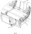
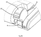
Figures 1A and1B show an actuator of the present invention positioned adjacent an aircraft seat base cushion; -
Figure 2 shows a view from above the actuator; -
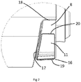
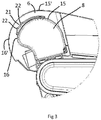
Figure 3 shows a side view of the actuator; -
Figure 4 shows an exploded view of the actuator; and -
Figure 5 shows an internal view of the actuator housing. - The present invention relates to actuators for recline mechanisms, in particular for those used in aircraft seats.
- With reference to the Figures, an
actuator 1 is provided for arecline mechanism 2 of anaircraft seat 3. In the example shown, the recline mechanism is a Hydrolok (RTM) hydraulic seat recline device. - With particular reference to the Figures, the
actuator 1 comprises aconnector 4 for connecting theactuator 1 to anelongate frame member 5 adjacent to aseat base cushion 6 of theaircraft seat 3. In the example shown, theconnector 4 comprises a twopiece frame 5 by asingle bolt 7. This, therefore, allows for easy removal of theactuator 1 for maintenance, adjustment or replacement. - The connected 4 is attached to a
housing 8 bybolts 9. Thebolts 9 are moveable withinslots 10, thus allowing for adjustment of the position of the housing along theelongate frame member 5 of theseat 3. The provision ofbolts 9 also means that thehousing 8 can be removed from theconnector 4 for replacement or repair. - A
trigger 11 is provided on an upper surface of thehousing 8 and is slideable in a forward direction (with reference to the direction of the seat) on the surface of thehousing 8, to pull acable 12 and thus release therecline mechanism 2 and, therefore, allow movement of the seat back 13. It is understood that, reference to "pull" acable 12, means that thecable 12 is displaced. Movement of thecable 12 andtrigger 11 is shown with particular reference toFigure 5 from which it will be seen that thetrigger 11 is connected to a rotating member, or rotor, 14 which is connected to thecable 12 via an attachment means 24 such that movement of thetrigger 11 causes rotation of the rotatingmember 14 and pulling of thecable 12. This in turn actuates therecline mechanism 2. When thetrigger 11 is released, it returns to an "at rest" position locking therecline mechanism 2, and thus the seat back 13, in position. - Whilst not specifically shown in the Figures, the
trigger 11 can be configured to also pull a second cable (not shown) when thetrigger 11 is moved in a rearward direction (with reference to the direction of the seat) and thus release a second control mechanism, for example a hydraulic piston and cylinder assembly, which controls movement of a second part of a seat, for example movement of a leg rest. - Remarkably, the present invention provides a significantly improved actuator for a recline mechanism, which does not suffer from the problems of known actuators. In this respect, by positioning the actuator adjacent to a seat base cushion of an aircraft seat, a much shorter cable is required than compared with the traditional location of the actuator in the arm rest. For example, when provided in an arm rest, the cable is usually about 100 cm in length, whilst the actuator of the present invention allows for a much shorter cable, for example of about 40 to 60 cm in length. This means that, even if the cable does stretch, the increase in overall length of the cable is much less than for a longer cable.
- In addition, the provision of a sliding
trigger 11, instead of a push button, means that sliding movement of thetrigger 11 can pull/displace the cable 12 a much greater distance than by pushing a button. Combined with the location of the actuator much closer to therecline mechanism 2, which means a shorter cable is required, the increased movement of thecable 12 by the actuator is such that failure of the actuator due to cable stretch is significantly reduced, if not completely prevented. - As shown in
Figure 3 , thehousing 8 is curved to correspond to the shape of theseat base cushion 6. In addition, when viewed from the side, thehousing 8 is sized such that itsupper surface 15 is lower than the upper surface 15' of an adjacentseat base cushion 6 and such that itsforward facing surface 16 is set rearward of the forward facing surface 16' of the adjacent seat base cushion. The shape and position of thehousing 8 relative to theseat base cushion 6 is advantageous because it reduces the risk of false activation of thetrigger 11 as a passenger locates themselves in theaircraft seat 3. - With reference to
Figure 2 , when viewed from above, a seat base cushion-facingside 17 of thehousing 8 is tapered from a larger width at or near a forward facingedge 16 of thehousing 8 to a smaller width at or near arear facing edge 18 of thehousing 8. The provision of atapered housing 8 helps to prevent forward movement of aseat base cushion 6 when thehousing 8 is placed next to theseat base cushion 6. It will also be seen that thehousing 8 is shaped to fit against a shaped profile of aseat base cushion 6. In the example shown, the shaped profile is created by a truncated corner of theseat base cushion 6. - In the example shown, the
trigger 11 is a curved plate, which follows the contours of the outer surface of thehousing 8 and is slideable forward from a position on theupper surface 15 of the housing to a position on theforward facing surface 16 of the housing. Whilst the trigger is slideable in a forward direction in the example shown, it will be appreciated that the trigger could be slideable in a rearward direction in other examples. It will further be appreciated that the trigger could be configured such that it is slideable in either a forward or rearward direction. - With particular reference to
Figure 2 the width of thetrigger 11 is tapered from a greater width at or near a forward facingend 19 of the trigger to a lesser width at or near a rearward facingend 20 of thetrigger 11. Referring toFigure 3 , agrip 21, in the form of a series ofridges 22, is provided towards theforward end 19 of thetrigger 11. Accordingly, the increased width of thetrigger 11 in this area not only provides a larger area to be gripped by the finger/s of a passenger, but also provides additional strength. - In the example shown, the
trigger 11 is biased to a non-actuated, rearward position by atorsion spring 23. - As shown in
Figure 4 , the rotatingmember 14 abuts a silicone O-ring 26 and is biased into abutment therewith by awave spring 25. This provides for smooth and predictable movement of the rotatingmember 14 and thus also thetrigger 11. - In order to minimise the risk of accidental actuation of the
trigger 11, theactuator 1 is positioned on a window side of eachaircraft seat 3. - The invention includes the following numbered embodiments.
- 1. An actuator for a recline mechanism, the actuator comprising:-
- (i) a connector for connecting the actuator to an elongate frame member adjacent to a seat base cushion of an aircraft seat;
- (ii) a housing; and
- (iii) a trigger for pulling a cable.
- 2. An actuator according to
embodiment 1, wherein the connector is removably attached to the housing. - 3. An actuator according to
embodiment - 4. An actuator according to
embodiment 3, wherein when the connector is connected to an elongate frame member of an aircraft seat, the position of the housing along the elongate frame member is adjustable. - 5. An actuator according to any preceding embodiment, wherein the connector is releasable from an elongate frame member of an aircraft seat by a single releasable lock.
- 6. An actuator according to
embodiment 5, wherein the lock comprises a single bolt. - 7. An actuator according to any preceding embodiment, wherein the housing is shaped to correspond to the shape of a seat base cushion.
- 8. An actuator according to any preceding embodiment, wherein when attached to an elongate frame member of an aircraft seat, the housing, and preferably also the trigger, does not protrude above or forward of an adjacent seat base cushion of the aircraft seat.
- 9. An actuator according to any preceding embodiment, wherein when attached to a elongate frame member of an aircraft seat, the housing is sized such that its upper surface is lower than the upper surface of an adjacent seat base cushion when viewed from the side and such that its forward facing surface is set rearward of the forward facing surface of an adjacent seat base cushion when viewed from the side.
- 10. An actuator according to any preceding embodiment, wherein the outer profile of the housing is curved.
- 11. An actuator according to any preceding embodiment, wherein the housing has a curved forward facing surface.
- 12. An actuator according to any preceding embodiment, wherein when viewed from above, a seat base cushion-facing side of the housing is tapered, having a larger width at or near a forward-facing edge of the housing and a smaller width at or near a rear-facing edge of the housing.
- 13. An actuator according to any preceding embodiment, wherein the housing is shaped to fit against a shaped profile of a seat base cushion.
- 14. An actuator according to any preceding embodiment, wherein the trigger is a sliding trigger.
- 15. An actuator according to any preceding embodiment, wherein the trigger is shaped to follow the contours of the outer surface of the housing.
- 16. An actuator according to any preceding embodiment, wherein the trigger is slideable forward and/or rearward, for example from a position on the upper surface of the housing.
- 17. An actuator according to any preceding embodiment, wherein the trigger is slideable forward from a position on the upper surface of the housing to a position on the forward facing surface of the housing, or from a position on the forward facing surface of the housing to a position on the upper surface of the housing.
- 18. An actuator according to any preceding embodiment, wherein the trigger is a low profile trigger.
- 19. An actuator according to any preceding embodiment, wherein the width of the trigger is tapered from a greater width at or near a forward facing end of the trigger to a lesser width at or near a reward facing end of the trigger.
- 20. An actuator according to any preceding embodiment, wherein the trigger comprises a grip.
- 21. An actuator according to any preceding embodiment, wherein the grip is provided at or near a forward end or rearward end of the trigger.
- 22. An actuator according to any preceding embodiment, wherein the trigger is biased to a non-actuated position.
- 23. An actuator according to any preceding embodiment, wherein the trigger is connected to a rotating member/rotor with the housing.
- 24. An actuator according to any preceding embodiment, wherein the rotating member/rotor comprises one or more attachment means for connection to one or more cables of a recline mechanism.
- 25. An actuator according to any preceding embodiment, wherein the rotating member/rotor abuts an abutment surface.
- 26. An actuator according to
embodiment 25, wherein the abutment surface is an O-ring. - 27. An actuator according to
embodiment 25 or 26, wherein the abutment surface is a low friction surface. - 28. An actuator according to any of
embodiments 25 to 27, wherein the abutment surface is a silicone abutment surface, for example a silicone O-ring. - 29. An actuator according to any of
embodiments 25 to 28, wherein the rotating member/rotor is biased into abutment with the abutment surface. - 30. An actuator according to any preceding embodiment, wherein the trigger is slideable in a first direction to pull a first cable and in a second direction to pull a second cable.
- 31. An aircraft seat comprising an actuator according to any preceding embodiment.
- 32. An aircraft seat according to embodiment 31, wherein the actuator is positioned adjacent a seat base cushion of the aircraft seat.
- 33. An aircraft seat according to embodiment 31 or 32, wherein the actuator is positioned on a window side of the aircraft seat.
- 34. An aircraft seat according to any of claims 31 to 33 comprising one or more control mechanisms.
- 35. A row of aircraft seats comprising one or more actuators according to any of
embodiments 1 to 30 and one or more control mechanisms, preferably one or more recline mechanisms. - It should be understood that various changes and modifications to the presently preferred embodiments described herein will be apparent to those skilled in the art. Such changes and modifications can be made without departing from the spirit and scope of the present invention and without diminishing its attendant advantages. It is therefore intended that such changes and modifications are covered by the appended claims.
Claims (15)
- An actuator for a recline mechanism, the actuator comprising:-(i) a connector for connecting the actuator to an elongate frame member adjacent to a seat base cushion of an aircraft seat;(ii) a housing; and(iii) a trigger for pulling a cable.
- An actuator according to claim 1, wherein the connector is removably attached to the housing, and/or wherein the position of the housing relative to the connector is adjustable, and/or wherein the connector is releasable from an elongate frame member of an aircraft seat by a single releasable lock.
- An actuator according to claim 1 or 2, wherein the housing is shaped to correspond to the shape of a seat base cushion.
- An actuator according to any preceding claim, wherein the outer profile of the housing is curved, and/or wherein the housing has a curved forward facing surface.
- An actuator according to any preceding claim, wherein when viewed from above, a seat base cushion-facing side of the housing is tapered, having a larger width at or near a forward-facing edge of the housing and a smaller width at or near a rear-facing edge of the housing.
- An actuator according to any preceding claim, wherein the housing is shaped to fit against a shaped profile of a seat base cushion.
- An actuator according to any preceding claim, wherein the trigger is a sliding trigger.
- An actuator according to any preceding claim, wherein the trigger is shaped to follow the contours of the outer surface of the housing.
- An actuator according to any preceding claim, wherein the trigger is slideable forward and/or rearward, for example from a position on the upper surface of the housing, and/or wherein the trigger is slideable forward from a position on the upper surface of the housing to a position on the forward facing surface of the housing, or from a position on the forward facing surface of the housing to a position on the upper surface of the housing.
- An actuator according to any preceding claim, wherein the width of the trigger is tapered from a greater width at or near a forward facing end of the trigger to a lesser width at or near a reward facing end of the trigger.
- An actuator according to any preceding claim, wherein the trigger is connected to a rotating member/rotor with the housing, optionally wherein the rotating member/rotor comprises one or more attachment means for connection to one or more cables of a recline mechanism, and/or wherein the rotating member/rotor abuts an abutment surface, optionally wherein the abutment surface is an O-ring, and/or wherein the abutment surface is a low friction surface.
- An actuator according to claim 11, wherein the rotating member/rotor is biased into abutment with the abutment surface.
- An actuator according to any preceding claim, wherein the trigger is slideable in a first direction to pull a first cable and in a second direction to pull a second cable.
- An aircraft seat comprising an actuator according to any preceding claim.
- A row of aircraft seats comprising one or more actuators according to any of claims 1 to 13 and one or more control mechanisms, preferably one or more recline mechanisms.
Priority Applications (1)
| Application Number | Priority Date | Filing Date | Title |
|---|---|---|---|
| PL18164541T PL3381806T3 (en) | 2017-03-31 | 2018-03-28 | Actuator |
Applications Claiming Priority (1)
| Application Number | Priority Date | Filing Date | Title |
|---|---|---|---|
| GBGB1705188.9A GB201705188D0 (en) | 2017-03-31 | 2017-03-31 | Actuator |
Publications (2)
| Publication Number | Publication Date |
|---|---|
| EP3381806A1 true EP3381806A1 (en) | 2018-10-03 |
| EP3381806B1 EP3381806B1 (en) | 2022-03-09 |
Family
ID=58682429
Family Applications (1)
| Application Number | Title | Priority Date | Filing Date |
|---|---|---|---|
| EP18164541.7A Not-in-force EP3381806B1 (en) | 2017-03-31 | 2018-03-28 | Actuator |
Country Status (5)
| Country | Link |
|---|---|
| US (1) | US10549669B2 (en) |
| EP (1) | EP3381806B1 (en) |
| CN (1) | CN108688813A (en) |
| GB (2) | GB201705188D0 (en) |
| PL (1) | PL3381806T3 (en) |
Families Citing this family (1)
| Publication number | Priority date | Publication date | Assignee | Title |
|---|---|---|---|---|
| USD945897S1 (en) * | 2020-04-27 | 2022-03-15 | Robert Bosch Gmbh | Remote for a display and operating device |
Citations (4)
| Publication number | Priority date | Publication date | Assignee | Title |
|---|---|---|---|---|
| US2998281A (en) * | 1958-06-12 | 1961-08-29 | Jacobs Mfg Co | Adjustable chair locking device |
| US20040145225A1 (en) * | 2003-01-23 | 2004-07-29 | Alter Roy H. | Modular jeep seat |
| JP2014218125A (en) * | 2013-05-07 | 2014-11-20 | トヨタ紡織株式会社 | Seat for vehicle |
| US20170050734A1 (en) * | 2015-08-21 | 2017-02-23 | Cessna Aircraft Company | Locking system for articulating aircraft seat |
Family Cites Families (21)
| Publication number | Priority date | Publication date | Assignee | Title |
|---|---|---|---|---|
| US2579305A (en) * | 1948-01-26 | 1951-12-18 | Sturgess Inc | Position-adjusting mechanism |
| US2833336A (en) * | 1955-10-25 | 1958-05-06 | Aerotherm Corp | Seats with angularly adjustable back |
| US3355963A (en) * | 1965-12-09 | 1967-12-05 | Ford Motor Co | Motion transfer device |
| US3762766A (en) * | 1971-06-04 | 1973-10-02 | American Seating Co | Airplane seat assembly |
| US4640142A (en) * | 1983-05-12 | 1987-02-03 | Ni Industries, Inc. | Adjustable automobile mirror system |
| US6070487A (en) * | 1997-11-12 | 2000-06-06 | Wescon Products Company | Panel mount cable control assembly |
| DE19853656B4 (en) * | 1998-11-20 | 2005-12-08 | Fico Cables, S.A., Rubi | connecting unit |
| US20080245177A1 (en) * | 2004-04-14 | 2008-10-09 | Bing-He Feng | Bicycle transmission mechanism |
| US7182402B1 (en) * | 2004-06-22 | 2007-02-27 | Timco Aviation Services, Inc. | Seat recline control override |
| US7303236B2 (en) * | 2005-03-01 | 2007-12-04 | Brunswich Corporation | Cable operated slider for vehicle seats |
| DE102006058388B4 (en) * | 2006-08-17 | 2008-06-19 | Johnson Controls Gmbh | Actuating device for a seat, in particular a motor vehicle seat |
| US8056219B2 (en) * | 2007-06-12 | 2011-11-15 | Panduit Corp. | One port plug unlocking tool |
| US8297147B2 (en) * | 2010-04-02 | 2012-10-30 | Yao-Chuan Wu | Guiding-wire controlling rod device for chair adjustment |
| JP5625810B2 (en) * | 2010-11-29 | 2014-11-19 | マツダ株式会社 | Vehicle split seat operation mechanism |
| GB2516433B (en) * | 2013-07-19 | 2016-02-17 | British Airways Plc | Aircraft passenger seat fixing system |
| US9604691B2 (en) * | 2014-02-20 | 2017-03-28 | Shimano Inc. | Bicycle operating device |
| US9789964B2 (en) * | 2014-03-31 | 2017-10-17 | B/E Aerospace, Inc. | Electronically actuated cable release mechanism for adjustable aircraft passenger seat features and method therefor |
| US9271573B2 (en) * | 2014-04-10 | 2016-03-01 | Dongguan Kentec Office Seating Co., Ltd. | Multifunction control device |
| US9656717B2 (en) * | 2015-02-06 | 2017-05-23 | Shimano Inc. | Bicycle operating device |
| US10021982B2 (en) * | 2016-08-08 | 2018-07-17 | Marcelo Mezzera | No-tools chair having detachable height and tilt control paddles |
| IT201700015349A1 (en) * | 2017-02-13 | 2018-08-13 | Campagnolo Srl | Device for operating the front derailleur of a bicycle |
-
2017
- 2017-03-31 GB GBGB1705188.9A patent/GB201705188D0/en not_active Ceased
-
2018
- 2018-03-28 GB GB1804964.3A patent/GB2561085B/en not_active Expired - Fee Related
- 2018-03-28 EP EP18164541.7A patent/EP3381806B1/en not_active Not-in-force
- 2018-03-28 PL PL18164541T patent/PL3381806T3/en unknown
- 2018-03-30 US US15/942,048 patent/US10549669B2/en active Active
- 2018-03-30 CN CN201810288523.9A patent/CN108688813A/en active Pending
Patent Citations (4)
| Publication number | Priority date | Publication date | Assignee | Title |
|---|---|---|---|---|
| US2998281A (en) * | 1958-06-12 | 1961-08-29 | Jacobs Mfg Co | Adjustable chair locking device |
| US20040145225A1 (en) * | 2003-01-23 | 2004-07-29 | Alter Roy H. | Modular jeep seat |
| JP2014218125A (en) * | 2013-05-07 | 2014-11-20 | トヨタ紡織株式会社 | Seat for vehicle |
| US20170050734A1 (en) * | 2015-08-21 | 2017-02-23 | Cessna Aircraft Company | Locking system for articulating aircraft seat |
Also Published As
| Publication number | Publication date |
|---|---|
| GB2561085B (en) | 2020-03-25 |
| GB201804964D0 (en) | 2018-05-09 |
| EP3381806B1 (en) | 2022-03-09 |
| GB2561085A (en) | 2018-10-03 |
| PL3381806T3 (en) | 2022-07-11 |
| CN108688813A (en) | 2018-10-23 |
| US10549669B2 (en) | 2020-02-04 |
| GB201705188D0 (en) | 2017-05-17 |
| US20180281650A1 (en) | 2018-10-04 |
Similar Documents
| Publication | Publication Date | Title |
|---|---|---|
| US10562425B2 (en) | Adjustment device for a headrest of a vehicle seat | |
| US6902238B1 (en) | Personal transportation seat in particular for aircraft passengers | |
| EP3056430B1 (en) | Dual-function seat actuator | |
| CN109987006B (en) | Adjustable thigh support for a vehicle seat | |
| KR20190013739A (en) | Chair or armchair with adjustable backrest | |
| US7484808B2 (en) | Vision improving system for a head restraint | |
| EP3335931A1 (en) | Deployable foot rest assembly | |
| EP3381806B1 (en) | Actuator | |
| JP2016052887A (en) | Lock releasing device for vehicular seat equipped with easy entry function, and lock releasing device operation method | |
| EP3844064A1 (en) | Airplane seat device | |
| US7918507B2 (en) | Device for limiting the adjustability of a vehicle seat | |
| EP3056429B1 (en) | Decoupled aircraft seat actuator | |
| KR101475212B1 (en) | Head restraint for a vehicle seat | |
| DE102020124093B4 (en) | Back rest recliner system for a vehicle seat of a motor vehicle and vehicle seat | |
| EP3846761B1 (en) | A tilt lock mechanism for a tilting wheelchair seat | |
| US9271886B2 (en) | Reactive headrest system for disabled individuals | |
| EP3100906A1 (en) | Shoulder adjuster | |
| EP2942231B1 (en) | Reclining seat | |
| US20240215732A1 (en) | Modular seat bottom cushion, and seat assembly comprising such a cushion | |
| JP2009101934A (en) | Headrest device for active headrest | |
| US6942293B2 (en) | Neck rest for the back rest of automobile seats, in particular rear seats | |
| JP6562005B2 (en) | Entry / exit support structure for vehicle seats | |
| EP2671469A1 (en) | Angle adjusting/positioning device for a backrest of a chair | |
| GB2506664A (en) | An armrest arranged to allow lateral movement | |
| EP3556334B1 (en) | A back/headrest for a vehicle |
Legal Events
| Date | Code | Title | Description |
|---|---|---|---|
| PUAI | Public reference made under article 153(3) epc to a published international application that has entered the european phase |
Free format text: ORIGINAL CODE: 0009012 |
|
| STAA | Information on the status of an ep patent application or granted ep patent |
Free format text: STATUS: THE APPLICATION HAS BEEN PUBLISHED |
|
| AK | Designated contracting states |
Kind code of ref document: A1 Designated state(s): AL AT BE BG CH CY CZ DE DK EE ES FI FR GB GR HR HU IE IS IT LI LT LU LV MC MK MT NL NO PL PT RO RS SE SI SK SM TR |
|
| AX | Request for extension of the european patent |
Extension state: BA ME |
|
| STAA | Information on the status of an ep patent application or granted ep patent |
Free format text: STATUS: REQUEST FOR EXAMINATION WAS MADE |
|
| 17P | Request for examination filed |
Effective date: 20190403 |
|
| RBV | Designated contracting states (corrected) |
Designated state(s): AL AT BE BG CH CY CZ DE DK EE ES FI FR GB GR HR HU IE IS IT LI LT LU LV MC MK MT NL NO PL PT RO RS SE SI SK SM TR |
|
| STAA | Information on the status of an ep patent application or granted ep patent |
Free format text: STATUS: EXAMINATION IS IN PROGRESS |
|
| 17Q | First examination report despatched |
Effective date: 20190806 |
|
| RAP1 | Party data changed (applicant data changed or rights of an application transferred) |
Owner name: ACRO AIRCRAFT SEATING LIMITED |
|
| GRAP | Despatch of communication of intention to grant a patent |
Free format text: ORIGINAL CODE: EPIDOSNIGR1 |
|
| STAA | Information on the status of an ep patent application or granted ep patent |
Free format text: STATUS: GRANT OF PATENT IS INTENDED |
|
| INTG | Intention to grant announced |
Effective date: 20211004 |
|
| GRAS | Grant fee paid |
Free format text: ORIGINAL CODE: EPIDOSNIGR3 |
|
| GRAA | (expected) grant |
Free format text: ORIGINAL CODE: 0009210 |
|
| STAA | Information on the status of an ep patent application or granted ep patent |
Free format text: STATUS: THE PATENT HAS BEEN GRANTED |
|
| AK | Designated contracting states |
Kind code of ref document: B1 Designated state(s): AL AT BE BG CH CY CZ DE DK EE ES FI FR GB GR HR HU IE IS IT LI LT LU LV MC MK MT NL NO PL PT RO RS SE SI SK SM TR |
|
| REG | Reference to a national code |
Ref country code: CH Ref legal event code: EP Ref country code: AT Ref legal event code: REF Ref document number: 1473958 Country of ref document: AT Kind code of ref document: T Effective date: 20220315 |
|
| REG | Reference to a national code |
Ref country code: IE Ref legal event code: FG4D |
|
| REG | Reference to a national code |
Ref country code: DE Ref legal event code: R096 Ref document number: 602018031843 Country of ref document: DE |
|
| REG | Reference to a national code |
Ref country code: LT Ref legal event code: MG9D |
|
| REG | Reference to a national code |
Ref country code: NL Ref legal event code: MP Effective date: 20220309 |
|
| PG25 | Lapsed in a contracting state [announced via postgrant information from national office to epo] |
Ref country code: SE Free format text: LAPSE BECAUSE OF FAILURE TO SUBMIT A TRANSLATION OF THE DESCRIPTION OR TO PAY THE FEE WITHIN THE PRESCRIBED TIME-LIMIT Effective date: 20220309 Ref country code: RS Free format text: LAPSE BECAUSE OF FAILURE TO SUBMIT A TRANSLATION OF THE DESCRIPTION OR TO PAY THE FEE WITHIN THE PRESCRIBED TIME-LIMIT Effective date: 20220309 Ref country code: NO Free format text: LAPSE BECAUSE OF FAILURE TO SUBMIT A TRANSLATION OF THE DESCRIPTION OR TO PAY THE FEE WITHIN THE PRESCRIBED TIME-LIMIT Effective date: 20220609 Ref country code: LT Free format text: LAPSE BECAUSE OF FAILURE TO SUBMIT A TRANSLATION OF THE DESCRIPTION OR TO PAY THE FEE WITHIN THE PRESCRIBED TIME-LIMIT Effective date: 20220309 Ref country code: HR Free format text: LAPSE BECAUSE OF FAILURE TO SUBMIT A TRANSLATION OF THE DESCRIPTION OR TO PAY THE FEE WITHIN THE PRESCRIBED TIME-LIMIT Effective date: 20220309 Ref country code: BG Free format text: LAPSE BECAUSE OF FAILURE TO SUBMIT A TRANSLATION OF THE DESCRIPTION OR TO PAY THE FEE WITHIN THE PRESCRIBED TIME-LIMIT Effective date: 20220609 |
|
| REG | Reference to a national code |
Ref country code: AT Ref legal event code: MK05 Ref document number: 1473958 Country of ref document: AT Kind code of ref document: T Effective date: 20220309 |
|
| PG25 | Lapsed in a contracting state [announced via postgrant information from national office to epo] |
Ref country code: LV Free format text: LAPSE BECAUSE OF FAILURE TO SUBMIT A TRANSLATION OF THE DESCRIPTION OR TO PAY THE FEE WITHIN THE PRESCRIBED TIME-LIMIT Effective date: 20220309 Ref country code: GR Free format text: LAPSE BECAUSE OF FAILURE TO SUBMIT A TRANSLATION OF THE DESCRIPTION OR TO PAY THE FEE WITHIN THE PRESCRIBED TIME-LIMIT Effective date: 20220610 Ref country code: FI Free format text: LAPSE BECAUSE OF FAILURE TO SUBMIT A TRANSLATION OF THE DESCRIPTION OR TO PAY THE FEE WITHIN THE PRESCRIBED TIME-LIMIT Effective date: 20220309 |
|
| PG25 | Lapsed in a contracting state [announced via postgrant information from national office to epo] |
Ref country code: NL Free format text: LAPSE BECAUSE OF FAILURE TO SUBMIT A TRANSLATION OF THE DESCRIPTION OR TO PAY THE FEE WITHIN THE PRESCRIBED TIME-LIMIT Effective date: 20220309 |
|
| PG25 | Lapsed in a contracting state [announced via postgrant information from national office to epo] |
Ref country code: SM Free format text: LAPSE BECAUSE OF FAILURE TO SUBMIT A TRANSLATION OF THE DESCRIPTION OR TO PAY THE FEE WITHIN THE PRESCRIBED TIME-LIMIT Effective date: 20220309 Ref country code: SK Free format text: LAPSE BECAUSE OF FAILURE TO SUBMIT A TRANSLATION OF THE DESCRIPTION OR TO PAY THE FEE WITHIN THE PRESCRIBED TIME-LIMIT Effective date: 20220309 Ref country code: RO Free format text: LAPSE BECAUSE OF FAILURE TO SUBMIT A TRANSLATION OF THE DESCRIPTION OR TO PAY THE FEE WITHIN THE PRESCRIBED TIME-LIMIT Effective date: 20220309 Ref country code: PT Free format text: LAPSE BECAUSE OF FAILURE TO SUBMIT A TRANSLATION OF THE DESCRIPTION OR TO PAY THE FEE WITHIN THE PRESCRIBED TIME-LIMIT Effective date: 20220711 Ref country code: ES Free format text: LAPSE BECAUSE OF FAILURE TO SUBMIT A TRANSLATION OF THE DESCRIPTION OR TO PAY THE FEE WITHIN THE PRESCRIBED TIME-LIMIT Effective date: 20220309 Ref country code: EE Free format text: LAPSE BECAUSE OF FAILURE TO SUBMIT A TRANSLATION OF THE DESCRIPTION OR TO PAY THE FEE WITHIN THE PRESCRIBED TIME-LIMIT Effective date: 20220309 Ref country code: CZ Free format text: LAPSE BECAUSE OF FAILURE TO SUBMIT A TRANSLATION OF THE DESCRIPTION OR TO PAY THE FEE WITHIN THE PRESCRIBED TIME-LIMIT Effective date: 20220309 Ref country code: AT Free format text: LAPSE BECAUSE OF FAILURE TO SUBMIT A TRANSLATION OF THE DESCRIPTION OR TO PAY THE FEE WITHIN THE PRESCRIBED TIME-LIMIT Effective date: 20220309 |
|
| REG | Reference to a national code |
Ref country code: CH Ref legal event code: PL |
|
| PG25 | Lapsed in a contracting state [announced via postgrant information from national office to epo] |
Ref country code: IS Free format text: LAPSE BECAUSE OF FAILURE TO SUBMIT A TRANSLATION OF THE DESCRIPTION OR TO PAY THE FEE WITHIN THE PRESCRIBED TIME-LIMIT Effective date: 20220709 Ref country code: AL Free format text: LAPSE BECAUSE OF FAILURE TO SUBMIT A TRANSLATION OF THE DESCRIPTION OR TO PAY THE FEE WITHIN THE PRESCRIBED TIME-LIMIT Effective date: 20220309 |
|
| REG | Reference to a national code |
Ref country code: BE Ref legal event code: MM Effective date: 20220331 |
|
| REG | Reference to a national code |
Ref country code: DE Ref legal event code: R097 Ref document number: 602018031843 Country of ref document: DE |
|
| PLBE | No opposition filed within time limit |
Free format text: ORIGINAL CODE: 0009261 |
|
| STAA | Information on the status of an ep patent application or granted ep patent |
Free format text: STATUS: NO OPPOSITION FILED WITHIN TIME LIMIT |
|
| PG25 | Lapsed in a contracting state [announced via postgrant information from national office to epo] |
Ref country code: MC Free format text: LAPSE BECAUSE OF FAILURE TO SUBMIT A TRANSLATION OF THE DESCRIPTION OR TO PAY THE FEE WITHIN THE PRESCRIBED TIME-LIMIT Effective date: 20220309 Ref country code: LU Free format text: LAPSE BECAUSE OF NON-PAYMENT OF DUE FEES Effective date: 20220328 Ref country code: LI Free format text: LAPSE BECAUSE OF NON-PAYMENT OF DUE FEES Effective date: 20220331 Ref country code: IE Free format text: LAPSE BECAUSE OF NON-PAYMENT OF DUE FEES Effective date: 20220328 Ref country code: DK Free format text: LAPSE BECAUSE OF FAILURE TO SUBMIT A TRANSLATION OF THE DESCRIPTION OR TO PAY THE FEE WITHIN THE PRESCRIBED TIME-LIMIT Effective date: 20220309 Ref country code: CH Free format text: LAPSE BECAUSE OF NON-PAYMENT OF DUE FEES Effective date: 20220331 |
|
| 26N | No opposition filed |
Effective date: 20221212 |
|
| PG25 | Lapsed in a contracting state [announced via postgrant information from national office to epo] |
Ref country code: SI Free format text: LAPSE BECAUSE OF FAILURE TO SUBMIT A TRANSLATION OF THE DESCRIPTION OR TO PAY THE FEE WITHIN THE PRESCRIBED TIME-LIMIT Effective date: 20220309 Ref country code: BE Free format text: LAPSE BECAUSE OF NON-PAYMENT OF DUE FEES Effective date: 20220331 |
|
| PGFP | Annual fee paid to national office [announced via postgrant information from national office to epo] |
Ref country code: IT Payment date: 20230322 Year of fee payment: 6 Ref country code: GB Payment date: 20230215 Year of fee payment: 6 |
|
| PGFP | Annual fee paid to national office [announced via postgrant information from national office to epo] |
Ref country code: PL Payment date: 20230222 Year of fee payment: 6 |
|
| PG25 | Lapsed in a contracting state [announced via postgrant information from national office to epo] |
Ref country code: HU Free format text: LAPSE BECAUSE OF FAILURE TO SUBMIT A TRANSLATION OF THE DESCRIPTION OR TO PAY THE FEE WITHIN THE PRESCRIBED TIME-LIMIT; INVALID AB INITIO Effective date: 20180328 |
|
| PG25 | Lapsed in a contracting state [announced via postgrant information from national office to epo] |
Ref country code: MK Free format text: LAPSE BECAUSE OF FAILURE TO SUBMIT A TRANSLATION OF THE DESCRIPTION OR TO PAY THE FEE WITHIN THE PRESCRIBED TIME-LIMIT Effective date: 20220309 Ref country code: CY Free format text: LAPSE BECAUSE OF FAILURE TO SUBMIT A TRANSLATION OF THE DESCRIPTION OR TO PAY THE FEE WITHIN THE PRESCRIBED TIME-LIMIT Effective date: 20220309 |
|
| PG25 | Lapsed in a contracting state [announced via postgrant information from national office to epo] |
Ref country code: MT Free format text: LAPSE BECAUSE OF FAILURE TO SUBMIT A TRANSLATION OF THE DESCRIPTION OR TO PAY THE FEE WITHIN THE PRESCRIBED TIME-LIMIT Effective date: 20220309 |
|
| PGFP | Annual fee paid to national office [announced via postgrant information from national office to epo] |
Ref country code: DE Payment date: 20240927 Year of fee payment: 7 |
|
| PGFP | Annual fee paid to national office [announced via postgrant information from national office to epo] |
Ref country code: FR Payment date: 20240927 Year of fee payment: 7 |
|
| P01 | Opt-out of the competence of the unified patent court (upc) registered |
Free format text: CASE NUMBER: UPC_APP_326218/2023 Effective date: 20230523 |
|
| GBPC | Gb: european patent ceased through non-payment of renewal fee |
Effective date: 20240328 |
|
| PG25 | Lapsed in a contracting state [announced via postgrant information from national office to epo] |
Ref country code: GB Free format text: LAPSE BECAUSE OF NON-PAYMENT OF DUE FEES Effective date: 20240328 |
|
| PG25 | Lapsed in a contracting state [announced via postgrant information from national office to epo] |
Ref country code: GB Free format text: LAPSE BECAUSE OF NON-PAYMENT OF DUE FEES Effective date: 20240328 |
|
| PG25 | Lapsed in a contracting state [announced via postgrant information from national office to epo] |
Ref country code: IT Free format text: LAPSE BECAUSE OF NON-PAYMENT OF DUE FEES Effective date: 20240328 |
|
| REG | Reference to a national code |
Ref country code: DE Ref legal event code: R119 Ref document number: 602018031843 Country of ref document: DE |
|
| PG25 | Lapsed in a contracting state [announced via postgrant information from national office to epo] |
Ref country code: PL Free format text: LAPSE BECAUSE OF NON-PAYMENT OF DUE FEES Effective date: 20240328 |
|
| PG25 | Lapsed in a contracting state [announced via postgrant information from national office to epo] |
Ref country code: TR Free format text: LAPSE BECAUSE OF FAILURE TO SUBMIT A TRANSLATION OF THE DESCRIPTION OR TO PAY THE FEE WITHIN THE PRESCRIBED TIME-LIMIT Effective date: 20220309 |
|
| PG25 | Lapsed in a contracting state [announced via postgrant information from national office to epo] |
Ref country code: DE Free format text: LAPSE BECAUSE OF NON-PAYMENT OF DUE FEES Effective date: 20251001 |
|
| PG25 | Lapsed in a contracting state [announced via postgrant information from national office to epo] |
Ref country code: FR Free format text: LAPSE BECAUSE OF NON-PAYMENT OF DUE FEES Effective date: 20250331 |