EP3381721A1 - Federungssystem - Google Patents
Federungssystem Download PDFInfo
- Publication number
- EP3381721A1 EP3381721A1 EP18163321.5A EP18163321A EP3381721A1 EP 3381721 A1 EP3381721 A1 EP 3381721A1 EP 18163321 A EP18163321 A EP 18163321A EP 3381721 A1 EP3381721 A1 EP 3381721A1
- Authority
- EP
- European Patent Office
- Prior art keywords
- flows
- flow
- hydraulic cylinder
- throttle valve
- suspension system
- Prior art date
- Legal status (The legal status is an assumption and is not a legal conclusion. Google has not performed a legal analysis and makes no representation as to the accuracy of the status listed.)
- Granted
Links
Images





Classifications
-
- B—PERFORMING OPERATIONS; TRANSPORTING
- B60—VEHICLES IN GENERAL
- B60G—VEHICLE SUSPENSION ARRANGEMENTS
- B60G17/00—Resilient suspensions having means for adjusting the spring or vibration-damper characteristics, for regulating the distance between a supporting surface and a sprung part of vehicle or for locking suspension during use to meet varying vehicular or surface conditions, e.g. due to speed or load
- B60G17/02—Spring characteristics, e.g. mechanical springs and mechanical adjusting means
- B60G17/033—Spring characteristics, e.g. mechanical springs and mechanical adjusting means characterised by regulating means acting on more than one spring
-
- B—PERFORMING OPERATIONS; TRANSPORTING
- B60—VEHICLES IN GENERAL
- B60G—VEHICLE SUSPENSION ARRANGEMENTS
- B60G17/00—Resilient suspensions having means for adjusting the spring or vibration-damper characteristics, for regulating the distance between a supporting surface and a sprung part of vehicle or for locking suspension during use to meet varying vehicular or surface conditions, e.g. due to speed or load
- B60G17/06—Characteristics of dampers, e.g. mechanical dampers
- B60G17/08—Characteristics of fluid dampers
-
- B—PERFORMING OPERATIONS; TRANSPORTING
- B60—VEHICLES IN GENERAL
- B60G—VEHICLE SUSPENSION ARRANGEMENTS
- B60G13/00—Resilient suspensions characterised by arrangement, location or type of vibration dampers
- B60G13/02—Resilient suspensions characterised by arrangement, location or type of vibration dampers having dampers dissipating energy, e.g. frictionally
- B60G13/06—Resilient suspensions characterised by arrangement, location or type of vibration dampers having dampers dissipating energy, e.g. frictionally of fluid type
- B60G13/08—Resilient suspensions characterised by arrangement, location or type of vibration dampers having dampers dissipating energy, e.g. frictionally of fluid type hydraulic
-
- B—PERFORMING OPERATIONS; TRANSPORTING
- B60—VEHICLES IN GENERAL
- B60G—VEHICLE SUSPENSION ARRANGEMENTS
- B60G17/00—Resilient suspensions having means for adjusting the spring or vibration-damper characteristics, for regulating the distance between a supporting surface and a sprung part of vehicle or for locking suspension during use to meet varying vehicular or surface conditions, e.g. due to speed or load
- B60G17/02—Spring characteristics, e.g. mechanical springs and mechanical adjusting means
- B60G17/04—Spring characteristics, e.g. mechanical springs and mechanical adjusting means fluid spring characteristics
-
- B—PERFORMING OPERATIONS; TRANSPORTING
- B60—VEHICLES IN GENERAL
- B60G—VEHICLE SUSPENSION ARRANGEMENTS
- B60G21/00—Interconnection systems for two or more resiliently-suspended wheels, e.g. for stabilising a vehicle body with respect to acceleration, deceleration or centrifugal forces
- B60G21/02—Interconnection systems for two or more resiliently-suspended wheels, e.g. for stabilising a vehicle body with respect to acceleration, deceleration or centrifugal forces permanently interconnected
- B60G21/06—Interconnection systems for two or more resiliently-suspended wheels, e.g. for stabilising a vehicle body with respect to acceleration, deceleration or centrifugal forces permanently interconnected fluid
-
- B—PERFORMING OPERATIONS; TRANSPORTING
- B62—LAND VEHICLES FOR TRAVELLING OTHERWISE THAN ON RAILS
- B62D—MOTOR VEHICLES; TRAILERS
- B62D33/00—Superstructures for load-carrying vehicles
- B62D33/06—Drivers' cabs
- B62D33/0604—Cabs insulated against vibrations or noise, e.g. with elastic suspension
- B62D33/0608—Cabs insulated against vibrations or noise, e.g. with elastic suspension pneumatic or hydraulic suspension
-
- F—MECHANICAL ENGINEERING; LIGHTING; HEATING; WEAPONS; BLASTING
- F16—ENGINEERING ELEMENTS AND UNITS; GENERAL MEASURES FOR PRODUCING AND MAINTAINING EFFECTIVE FUNCTIONING OF MACHINES OR INSTALLATIONS; THERMAL INSULATION IN GENERAL
- F16F—SPRINGS; SHOCK-ABSORBERS; MEANS FOR DAMPING VIBRATION
- F16F9/00—Springs, vibration-dampers, shock-absorbers, or similarly-constructed movement-dampers using a fluid or the equivalent as damping medium
- F16F9/06—Springs, vibration-dampers, shock-absorbers, or similarly-constructed movement-dampers using a fluid or the equivalent as damping medium using both gas and liquid
- F16F9/08—Springs, vibration-dampers, shock-absorbers, or similarly-constructed movement-dampers using a fluid or the equivalent as damping medium using both gas and liquid where gas is in a chamber with a flexible wall
- F16F9/096—Springs, vibration-dampers, shock-absorbers, or similarly-constructed movement-dampers using a fluid or the equivalent as damping medium using both gas and liquid where gas is in a chamber with a flexible wall comprising a hydropneumatic accumulator of the membrane type provided on the upper or the lower end of a damper or separately from or laterally on the damper
-
- F—MECHANICAL ENGINEERING; LIGHTING; HEATING; WEAPONS; BLASTING
- F16—ENGINEERING ELEMENTS AND UNITS; GENERAL MEASURES FOR PRODUCING AND MAINTAINING EFFECTIVE FUNCTIONING OF MACHINES OR INSTALLATIONS; THERMAL INSULATION IN GENERAL
- F16F—SPRINGS; SHOCK-ABSORBERS; MEANS FOR DAMPING VIBRATION
- F16F9/00—Springs, vibration-dampers, shock-absorbers, or similarly-constructed movement-dampers using a fluid or the equivalent as damping medium
- F16F9/32—Details
- F16F9/44—Means on or in the damper for manual or non-automatic adjustment; such means combined with temperature correction
- F16F9/46—Means on or in the damper for manual or non-automatic adjustment; such means combined with temperature correction allowing control from a distance, i.e. location of means for control input being remote from site of valves, e.g. on damper external wall
- F16F9/466—Throttling control, i.e. regulation of flow passage geometry
-
- B—PERFORMING OPERATIONS; TRANSPORTING
- B60—VEHICLES IN GENERAL
- B60G—VEHICLE SUSPENSION ARRANGEMENTS
- B60G2202/00—Indexing codes relating to the type of spring, damper or actuator
- B60G2202/20—Type of damper
- B60G2202/24—Fluid damper
-
- B—PERFORMING OPERATIONS; TRANSPORTING
- B60—VEHICLES IN GENERAL
- B60G—VEHICLE SUSPENSION ARRANGEMENTS
- B60G2204/00—Indexing codes related to suspensions per se or to auxiliary parts
- B60G2204/10—Mounting of suspension elements
- B60G2204/16—Mounting of vehicle body on chassis
- B60G2204/162—Cabins, e.g. for trucks, tractors
-
- B—PERFORMING OPERATIONS; TRANSPORTING
- B60—VEHICLES IN GENERAL
- B60G—VEHICLE SUSPENSION ARRANGEMENTS
- B60G2204/00—Indexing codes related to suspensions per se or to auxiliary parts
- B60G2204/80—Interactive suspensions; arrangement affecting more than one suspension unit
- B60G2204/83—Type of interconnection
- B60G2204/8304—Type of interconnection using a fluid
Definitions
- the invention relates to a suspension system, in particular a cabin suspension comprising at least one hydraulic cylinder with a piston chamber and a rod space, wherein the hydraulic cylinder with at least one hydraulic accumulator for compression and rebounding is in communication.
- suspension systems are used, for example, in working machines such as tractors or the like.
- working machines can be additionally equipped with a cabin suspension in addition to the usual suspension suspensions.
- the EP 2 197 697 B1 describes a suspension system, in particular a cabin suspension, which has a hydraulic cylinder which communicates with a hydraulic accumulator.
- the system includes a throttle valve with two throttles. During compression of the hydraulic cylinder, the entire flow of fluid displaced from the piston chamber first flows through the first throttle and then divides into a partial flow which flows into the hydraulic accumulator and a partial flow which flows into the rod chamber of the hydraulic cylinder.
- the two throttles have opening cross-sections which correspond to the ratio of piston to ring surface of the hydraulic cylinder.
- the object of the invention is to provide a suspension system which has a simple structure with relatively few components and at the same time ensures a defined, optionally adjustable, damping.
- the system should be characterized by a long life and reliable operation. It should be in operation The load on the individual components should be as low as possible and power losses should be minimized.
- the damping of the suspension system should be as identical as possible during compression and rebound, the damping should be specifically adjustable.
- the stiffness of the suspension should be independent of the damping selectable or adjustable. Furthermore, should be avoided with the suspension system unwanted inclinations, such as a car when cornering.
- the system has a branching for dividing a fluid flow from the piston chamber during compression into a partial flow, which flows to a rod space of a hydraulic cylinder and a partial flow, which flows through a throttle valve to a hydraulic accumulator.
- a partial flow which flows through a throttle valve to a hydraulic accumulator.
- the invention also enables a reduction of the throttle. This has a favorable effect on the required installation space. This creates a compact design.
- the suspension system according to the invention simultaneously ensures a defined and precisely adjustable damping, wherein the stiffness of the suspension system during compression and rebound can be influenced by means of a bias pressure in the hydraulic accumulator.
- the suspension system according to the invention allows a variable throttling and comes out with very few components. There is only a relatively small regulatory effort required, thereby ensuring a precise control accuracy and impairments are avoided. Furthermore, the suspension system according to the invention has a small footprint. As a result, the system can be implemented cost-effectively and ensures high reliability. In addition, it is less prone to failure and inexpensive to produce.
- the deviation of the volume flows between the rebound and rebound maximum 20%, preferably at most 10%, especially at most 5%.
- the fluid flow which flows during compression by the throttle of the valve largely corresponds to the fluid flow which flows during rebound over the throttle of the valve.
- a proportional throttle valve is used.
- the proportional throttle valve it is possible to perform the control process with identical damping only once during compression and rebound of the cylinder and at the same time to throttle defined.
- a rod is arranged in the rod space, which has almost the same cross-section as an annular surface which is formed around the rod of the piston.
- the cross-section of the rod deviates a maximum of 15%, preferably a maximum of 10%, in particular a maximum of 5% of the cross-section of the annular surface.
- the cross section of the rod corresponds to the cross section of the annular surface which is formed around the rod of the piston.
- the suspension system according to the invention comprises non-return valves which block in a flow direction and open in the other direction of flow.
- the non-return valves are preferably non-return valves, in particular non-return valves being used.
- a backflow preventer is arranged in a fluid path between the piston chamber and the throttle valve, which opens during compression and locks during rebound.
- a backflow preventer can be arranged in a fluid path between the piston chamber and the hydraulic accumulator, which locks during compression and opens during rebound.
- At least one hydraulic cylinder is connected to a further hydraulic cylinder via a cross-circuit.
- the crosswise interconnection of the cylinders results in improved roll stability. As a result, for example, an undesired bending away of the cabin during cornering by the sinking of only one hydraulic cylinder is effectively prevented.
- the entire partial flow preferably flows from the piston chamber to the hydraulic accumulator through the throttle valve.
- a bypass flow directly to a hydraulic accumulator is avoided. This ensures a defined, adjustable damping.
- the fluid streams preferably share the same ratio during compression, so that the partial flow flowing into the rod space of a hydraulic cylinder is the same as the partial flow, which is passed through the throttle to a hydraulic accumulator.
- FIG. 1 shows a schematic representation of a tractor with a cabin suspension.
- the cabin 1 is seen in the direction of travel supported on its front side via a bearing 2 and on its rear side via hydraulic cylinders 3.
- the hydraulic cylinders 3 are connected to a hydraulic accumulator 4 in connection.
- a throttle 5 is arranged in a fluid path between the hydraulic cylinder 3 and the hydraulic accumulator 4.
- the hydraulic cylinders 3 ensure a suspension, in particular of vertical movements of the car. 1
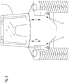
- FIG. 2 shows a schematic view of the tractor from behind. It can be seen that the cabin 1 of the tractor is sprung by two hydraulic cylinders 3.
- FIG. 3 shows a perspective view of the cabin suspension.
- the front bearing 2 comprises two elastic elements 6, which are designed in the embodiment as rubber blocks.
- the elastic members 6 connect a frame 7 of the cab to the chassis 8 of the vehicle.
- the elastic elements 6 provide for a decoupling of the movements of the chassis 8 of the frame 7 of the car 1.
- the cab suspension comprises a positioning system 9.
- the positioning system 9 brings the car into an initial rest position, depending on the load.
- the positioning system 9 the cabin in a corresponding starting position bring so that regardless of the weight of the driver always the same starting position of the suspension system is made.
- the positioning system 9 corresponding sensors to adjust the position of the hydraulic cylinder 3 accordingly.
- the positioning system 9 is part of the cabin suspension.
- the positioning system 9 is state of the art, so will not be discussed in more detail in the further description of the invention.
- FIG. 4 shows a hydraulic cylinder 3 of the suspension system according to the invention during compression.
- the hydraulic cylinder 3 comprises a rod space 11 and a piston space 12.
- a fluid flow 13 from the piston chamber 12 of the hydraulic cylinder 3 is generated by the movement of the piston 10 downwards by a specific travel.
- the fluid flow 13 flows via a non-return valve 14, which opens during compression.
- the fluid flow 13 is divided into a partial flow 16 which flows into the rod space 11 of the hydraulic cylinder 3 and a partial flow 17 which flows through the throttle 18 of a throttle valve 19 to the hydraulic accumulator 4.
- the throttle valve 19 includes a drive 20 which is formed in the embodiment as an electromagnetic actuator.
- the throttle valve 19 includes ports for the corresponding fluid paths.
- the drive 20, comprises a return spring, not shown. About the return spring, the throttle valve 19 can return to its original position.
- the hydraulic accumulator 4 is formed in the embodiment of a diaphragm accumulator.
- the hydraulic accumulator 4 has a separation membrane 21 which separates a gas side 22 from a fluid side 23.
- the hydraulic accumulator 4 can be biased in dependence on the fluid pressure on the gas side 22 and forms an energy reservoir for the stored hydraulic energy.
- the suspension system comprises a further non-return valve 24, which is closed during compression and thus prevents fluid flow from the piston chamber 12 of the hydraulic cylinder 3 directly to the hydraulic accumulator 4.
- the backflow preventer 24 thus ensures that no bypass flow takes place, so that the fluid flow from the piston chamber 12 of the Hydraulic cylinder 3 is guided to the hydraulic accumulator 4 via the throttle 18 of the throttle valve 19.
- FIG. 5 shows the suspension system during rebound.
- the piston 10 moves in accordance with the arrow direction shown upwards and it is a fluid volume displaced from the rod chamber 11 of the hydraulic cylinder 3, which corresponds to the travel of the piston multiplied by the annular surface 25 which is formed around the cross-sectional area 26 of the rod.
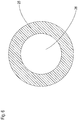
- the two surfaces 25, 26 are in FIG. 6 shown.
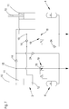
- FIG. 7 shows a suspension system with two hydraulic cylinders 3, which are connected to a cross-connection.
- the operation of this funnelverscnies is based on the FIGS. 8 and 9 explained, which are simplified for clarity. They are not complete and non-functional in this form. The full, functional version is in FIG. 7 shown.
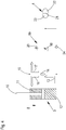
- FIG. 8 shows a simplified representation of the cross-connection during compression. From the overlooking FIG. 8 right hydraulic cylinder 3, a fluid flow 13 is generated from the piston chamber 12 of the hydraulic cylinder 3. At a junction 15, the fluid flow 13 is divided into a partial flow 16 to the rod chamber 11 of the left with respect to the figure hydraulic cylinder 3 and a partial flow 17 through a throttle 18 of the throttle valve 19 to a hydraulic accumulator 4. All return valve 14 are open during compression , All backflow preventer 24 are closed during compression and prevent a bypass flow of the fluid streams 13 directly to a hydraulic accumulator 4, so that the fluid streams 13 are forced to first flow through a throttle valve 19.
- FIG. 9 shows a simplified representation of the cross-connection during rebound. Accordingly, the pistons 10 of both hydraulic cylinders 3 move upward. From the overlooking FIG. 8 left hydraulic cylinder 3, a fluid flow 27 flows from the rod chamber 11 via the throttle 18 of the throttle valve 19. The fluid flow 27 forms with a further fluid stream 28, which is fed from the hydraulic accumulator 24, a fluid flow 29, which via the backflow preventer 24 to the piston chamber 12 of the with respect to FIG. 8 right hydraulic cylinder 3 flows. All return valve 24 are open during rebound. All non-return valve 14 are closed during rebound and prevent flow of the fluid streams 27 directly to the piston chamber 12, so that the fluid flow 27 are forced to flow through a throttle 18.
Landscapes
- Engineering & Computer Science (AREA)
- Mechanical Engineering (AREA)
- General Engineering & Computer Science (AREA)
- Chemical & Material Sciences (AREA)
- Combustion & Propulsion (AREA)
- Transportation (AREA)
- Vehicle Body Suspensions (AREA)
Abstract
Description
- Die Erfindung betrifft ein Federungssystem, insbesondere eine Kabinenfederung, umfassend mindestens einen Hydraulikzylinder mit einem Kolbenraum und einem Stangenraum, wobei der Hydraulikzylinder mit mindestens einem Hydrospeicher zum Einfedern und Ausfedern in Verbindung steht.
- Solche Federungssysteme kommen beispielsweise bei Arbeitsmaschinen wie Traktoren oder dergleichen zum Einsatz. Um dem Fahrer einen möglichst großen Komfort zu bieten, können Arbeitsmaschinen neben den üblichen Fahrwerksfederungen zusätzlich mit einer Kabinenfederung ausgestattet sein.
- Bei herkömmlichen Systemen ist zur Gewährleistung einer möglichst gleichmäßigen Dämpfung des Federungssystems häufig eine aufwendige Regelungstechnik erforderlich. Dabei wird meist eine kostspielige Sensorik benötigt, die den hydraulischen Zustand des jeweiligen Hydraulikzylinders erfasst.
- Die
EP 2 197 697 B1 beschreibt ein Federungssystem, insbesondere eine Kabinenfederung, die einen Hydraulikzylinder aufweist, der mit einem Hydrospeicher in Verbindung steht. Das System umfasst ein Drosselventil mit zwei Drosseln. Beim Einfedern des Hydraulikzylinders fließt der gesamte aus dem Kolbenraum verdrängte Fluidstrom zunächst über die erste Drossel und teilt sich dann in einen Teilstrom auf, der in den Hydrospeicher fließt und einen Teilstrom, der in den Stangenraum des Hydraulikzylinders fließt. - Beim Ausfedern strömt der gesamte aus dem Stangenraum verdrängte Fluidstrom über die zweite Drossel zum Kolbenraum des Hydraulikzylinders, wobei zusätzlich Fluid aus dem Hydrospeicher in den Kolbenraum eingespeist wird.
- Die beiden Drosseln weisen Öffnungsquerschnitte auf, die dem Verhältnis von Kolben- zu Ringfläche des Hydraulikzylinders entsprechen. Dadurch wird bei gleicher Ventilstellung die Bewegung beim Einfedern und Ausfedern gleichmäßig gedämpft, da der Fluidstrom in Abhängigkeit der Bewegungsrichtung entweder über die eine oder die andere Drossel fließt.
- Diese Konstruktion mit zwei Drosseln ist aufwendig und erfordert einen hohen Aufwand um die Drosseln zu dimensionieren. bedingt Leistungsverluste, die beispielsweise auch zu einer Erwärmung der Hydraulikflüssigkeit führen können. Weiterhin werden die Bauteile während des Betriebs verhältnismäßig stark belastet.
- Aufgabe der Erfindung ist es, ein Federungssystem anzugeben, das einen einfachen Aufbau mit verhältnismäßig wenigen Komponenten aufweist und dabei gleichzeitig eine definierte, gegebenenfalls einstellbare, Dämpfung gewährleistet. Das System soll sich durch eine lange Lebensdauer und eine zuverlässige Betriebsweise auszeichnen. Dabei soll im Betrieb die Belastung der einzelnen Komponenten möglichst gering sein und Leistungsverluste sollen minimiert werden. Die Dämpfung des Federungssystems soll beim Einfedern und Ausfedern möglichst identisch sein, wobei die Dämpfung gezielt einstellbar sein soll. Die Steifigkeit der Federung soll unabhängig von der Dämpfung wählbar, beziehungsweise einstellbar sein. Weiterhin sollen mit dem Federungssystem unerwünschte Neigungen, beispielsweise einer Kabine bei einer Kurvenfahrt, vermieden werden.
- Diese Aufgabe wird erfindungsgemäß durch ein Federungssystem mit den Merkmalen des Anspruchs 1 und einem Verfahren mit den Merkmalen des Anspruchs 9 gelöst. Bevorzugte Varianten sind den Unteransprüchen, der Beschreibung und den Zeichnungen zu entnehmen.
- Erfindungsgemäß weist das System eine Verzweigung auf zur Aufteilung eines Fluidstroms aus dem Kolbenraum beim Einfedern in einen Teilstrom, der zu einem Stangenraum eines Hydraulikzylinders fließt und einen Teilstrom, der durch ein Drosselventil zu einem Hydrospeicher fließt. Durch die erfindungsgemäße Aufteilung fließt beim Einfedern nicht der gesamte Fluidstrom aus dem Kolbenraum des Hydraulikzylinders über die Drossel sondern nur ein Teilstrom. Vor der Drossel wird der andere Teilstrom abgezweigt und wird unmittelbar zurückgeführt in einen Stangenraum eines Hydraulikzylinders. Dabei kann es sich um den Stangenraum des gleichen Hydraulikzylinders handeln oder um den Stangenraum eines anderen Hydraulikzylinders. Dadurch, dass nicht der gesamte Fluidstrom über die Drossel geführt wird, werden Leistungsverluste, wie beispielsweise Druckverluste, reduziert und auch eine Erwärmung der Hydraulikflüssigkeit wird minimiert. Weiterhin wird die Drossel nicht so stark belastet, was sich auch positiv auf die Lebensdauer des Federungssystems auswirken kann. Die Erfindung ermöglicht auch eine Verkleinerung der Drossel. Dies wirkt sich günstig auf den benötigten Bauraum aus. Dadurch wird eine kompakte Konstruktion geschaffen. Das erfindungsgemäße Federungssystem gewährleistet gleichzeitig eine definierte und präzise einstellbare Dämpfung, wobei die Steifigkeit des Federungssystems beim Ein- und Ausfedern beeinflusst werden kann, mittels einem Vorspannungsdruck im Hydrospeicher.
- Das erfindungsgemäße Federungssystem ermöglicht eine variable Drosselung und kommt dabei mit sehr wenigen Bauteilen aus. Es ist nur ein verhältnismäßig geringer Regelungsaufwand erforderlich, dadurch wird eine präzise Ansteuerungsgenauigkeit gewährleistet und Beeinträchtigungen werden vermieden. Weiterhin weist das erfindungsgemäße Federungssystem einen geringen Platzbedarf auf. Dadurch lässt sich das System kostengünstig realisieren und gewährleistet eine hohe Zuverlässigkeit. Zudem ist es wenig störungsanfällig und kostengünstig herstellbar.
- Als besonders günstig erweist es sich, wenn beim Ausfedern der gesamte Fluidstrom aus dem Stangenraum durch das Drosselventil fließt, ohne dass es zuvor zu einer Aufteilung kommt.
- Dabei erweist es sich als besonders günstig, wenn beim Einfedern und Ausfedern bei gleicher Verfahrgeschwindigkeit ungefähr gleichgroße Mengen durch das Drosselventil fließen, wobei die Abweichung der Volumenströme zwischen dem Ein- und Ausfedern maximal 20 %, vorzugsweise maximal 10 %, insbesondere maximal 5 % beträgt. Bei einer besonders günstigen Variante der Erfindung entspricht der Fluidstrom, der beim Einfedern durch die Drossel des Ventils fließt, weitgehend dem Fluidstrom, der beim Ausfedern über die Drossel des Ventils fließt.
- Bei einer besonders günstigen Variante der Erfindung kommt ein Proportionaldrosselventil zum Einsatz. Durch den Einsatz des Proportionaldrosselventils besteht die Möglichkeit, beim Ein- und Ausfedern des Zylinders den Ansteuervorgang bei identischer Dämpfung nur einmalig durchführen zu müssen und gleichzeitig definiert zu drosseln.
- Bei einer besonders günstigen Variante der Erfindung ist im Stangenraum eine Stange angeordnet, die nahezu den gleichen Querschnitt aufweist, wie eine Ringfläche, die um die Stange des Kolbens herum gebildet wird. Der Querschnitt der Stange weicht dabei maximal 15%, vorzugsweise maximal 10 % insbesondere maximal 5 % vom Querschnitt der Ringfläche ab. Bei einer besonders günstigen Variante der Erfindung,
Bei einer besonders günstigen Variante der Erfindung entspricht der Querschnitt der Stange dem Querschnitt der Ringfläche, die um die Stange des Kolbens herum gebildet wird. - Beim Einfedern um einen gewissen Stellweg des Kolbens wird eine Fluidmenge aus dem Kolbenraum verdrängt, welche der Fläche des Kolbens multipliziert mit diesem Stellweg entspricht. Beim Ausfedern wird aus dem Stangenraum eine Fluidmenge verdrängt, welche der Ringfläche um die Stange multipliziert mit dem jeweiligen Stellweg entspricht. Die Differenz dieser beiden Volumina beim Einfedern und beim Ausfedern, bei einem gleichen Stellweg, entspricht einem Fluidvolumen, das sich aus dem Produkt der Querschnittsfläche der Stange und dem entsprechenden Stellweg ergibt. Entspricht die Querschnittsfläche der Stange der Ringfläche, dann ist beim Einfedern der Teilstrom, welcher wird in einen Stangenraum des Hydraulikzylinders zurückgeführt genau so groß wie der Teilstrom, der dann über die Drossel des Ventils geführt wird. Dabei wird vorausgesetzt, dass die Verfahrgeschwindigkeit des Kolben beim Einfedern und Ausfedern gleich groß ist. Durch diese Ausgestaltung wird beim Ein- und Ausfedern eine identische Dämpfung gewährleistet.
- Bei einer besonders vorteilhaften Variante der Erfindung kommt pro Hydraulikzylinder nur eine Drossel zum Einsatz, über welche Fluidströme beim Einfedern und Ausfedern fließen.
- Im Gegensatz zu herkömmlichen Varianten nach dem Stand der Technik sind somit nicht zwei Drosseln erforderlich, um eine identische Dämpfung zu gewährleisten, sondern nur eine Drossel.
- Vorzugsweise fließt beim Ausfedern der gesamte Fluidstrom aus dem Stangenraum durch das Drosselventil. Als besonders günstig erweist es sich, wenn der beim Ausfedern erzeugte Fluidstrom aus dem Stangenraum über die gleiche Drossel fließt wie der beim Einfedern erzeugte Teilstrom, wobei der Fluidstrom aus dem Kolbenraum beim Einfedern vor der Drossel aufgeteilt wird in einen Teilstrom, welcher unmittelbar zurückfließt in einen Stangenraum eines Hydraulikzylinders und einen Teilstrom, der durch die Drossel geführt wird.
- Bei einer besonders bevorzugten Ausführungsform umfasst das erfindungsgemäße Federungssystem Rückflussverhinderer, die in eine Durchflussrichtung sperren und in die andere Durchflussrichtung öffnen. Vorzugsweise handelt es sich bei den Rückflussverhinderern um Rückschlagarmaturen, wobei insbesondere Rückschlagventile zum Einsatz kommen.
- Bei einer besonders günstigen Variante der Erfindung ist in einem Fluidweg zwischen dem Kolbenraum und dem Drosselventil ein Rückflussverhinderer angeordnet, der sich beim Einfedern öffnet und beim Ausfedern sperrt.
- Ergänzend oder alternativ kann in einem Fluidweg zwischen dem Kolbenraum und dem Hydrospeicher ein Rückflussverhinderer angeordnet sein, der sich beim Einfedern sperrt und beim Ausfedern öffnet.
- Bei einer vorteilhaften Variante der Erfindung ist mindestens ein Hydraulikzylinder mit einem weiteren Hydraulikzylinder über eine Kreuzschaltung verbunden. Durch die kreuzweise Verschaltung der Zylinder wird eine verbesserte Wankstabilität erreicht. Dadurch wird beispielsweise ein unerwünschtes Wegbiegen der Kabine bei einer Kurvenfahrt durch das Wegsinken nur eines Hydraulikzylinders wirksam verhindert.
- Vorzugsweise fließt beim Einfedern der gesamte Teilstrom vom Kolbenraum zum Hydrospeicher durch das Drosselventil. Eine Bypassströmung unmittelbar zu einem Hydrospeicher wird vermieden. Dadurch wird eine definierte, einstellbare Dämpfung gewährleistet.
- Die Fluidströme teilen sich beim Einfedern vorzugsweise im gleichen Verhältnis auf, sodass der Teilstrom, der in den Stangenraum eines Hydraulikzylinders fließt, genauso groß ist wie der Teilstrom, der durch die Drossel zu einem Hydrospeicher geleitet wird.
- Weitere Merkmale und Vorteile der Erfindung ergeben sich aus der Beschreibung von Ausführungsbeispielen anhand von Zeichnungen und aus den Zeichnungen selbst.
- Dabei zeigt:
-
Figur 1 eine schematische Darstellung einer Kabinenfederung eines Traktors in seitlicher Ansicht, -
Figur 2 eine schematische Darstellung einer Kabinenfederung eines Traktors von hinten gesehen, -
Figur 3 eine perspektivische Darstellung einer Kabinenfederung, -
Figur 4 ein Federungssystem mit einem Hydraulikzylinder beim Einfedern, -
Figur 5 ein Federungssystem mit einem Hydraulikzylinder beim Ausfedern, -
Figur 6 ein Verhältnis eines Stangenquerschnitts zu einer Ringfläche auf der Stangenseite, -
Figur 7 ein Federungssystem mit zwei Hydraulikzylindern in Kreuzverschaltung, -
Figur 8 eine vereinfachte Darstellung der Kreuzverschaltung beim Einfedern, -
Figur 9 eine vereinfachte Darstellung der Kreuzverschaltung beim Ausfedern. -
Figur 1 zeigt eine schematische Darstellung eines Traktors mit einer Kabinenfederung. Die Kabine 1 ist in Fahrtrichtung gesehen an ihrer Vorderseite über eine Lagerung 2 und an ihrer Hinterseite über Hydraulikzylinder 3 abgestützt. Die Hydraulikzylinder 3 stehen mit einem Hydrospeicher 4 in Verbindung. In einem Fluidweg zwischen dem Hydraulikzylinder 3 und dem Hydrospeicher 4 ist eine Drossel 5 angeordnet. Die Hydraulikzylinder 3 gewährleisten eine Federung, insbesondere von vertikalen Bewegungen der Kabine 1. -
Figur 2 zeigt eine schematische Ansicht des Traktors von hinten. Man erkennt, dass die Kabine 1 des Traktors über zwei Hydraulikzylinder 3 gefedert ist. -
Figur 3 zeigt eine perspektivische Darstellung der Kabinenfederung. Das vordere Lager 2 umfasst zwei elastische Elemente 6, die im Ausführungsbeispiel als Gummiklötze ausgeführt sind. Die elastischen Elemente 6 verbinden einen Rahmen 7 der Kabine mit dem Fahrgestell 8 des Fahrzeugs. - Die elastischen Elemente 6 sorgen für eine Entkopplung der Bewegungen des Fahrgestells 8 von dem Rahmen 7 der Kabine 1. An der Hinterseite wird der Rahmen 7 der Kabine 1 vom Fahrgestell 8 über die Hydraulikzylinder 3 in ihren Bewegungen entkoppelt. Die Kabinenfederung umfasst ein Positionierungssystem 9. Das Positionierungssystem 9 bringt die Kabine je nach Belastung in eine anfängliche Ruheposition. Je nach Gewicht des Fahrers kann das Positionierungssystem 9 die Kabine in eine entsprechende Ausgangslage bringen, sodass unabhängig vom Eigengewicht des Fahrers immer die gleiche Ausgangslage des Federungssystems hergestellt wird. Dazu weist das Positionierungssystem 9 entsprechende Sensoren auf, um die Stellung der Hydraulikzylinder 3 entsprechend einzustellen.
- Das Positionierungssystem 9 ist Teil der Kabinenfederung. Das Positionierungssystem 9 ist Stand der Technik, somit wird bei der weiteren Beschreibung der Erfindung nicht näher darauf eingegangen.
-
Figur 4 zeigt einen Hydraulikzylinder 3 des erfindungsgemäßen Federungssystems beim Einfedern. Beim Einfedern bewegt sich der Kolben 10 des Hydraulikzylinders 3 nach unten. Der Hydraulikzylinder 3 umfasst einen Stangenraum 11 und einen Kolbenraum 12. - Beim Einfedern wird durch die Bewegung des Kolbens 10 nach unten um einen bestimmten Stellweg ein Fluidstrom 13 aus dem Kolbenraum 12 des Hydraulikzylinders 3 erzeugt. Der Fluidstrom 13 fließt über einen Rückflussverhinderer 14, welcher beim Einfedern öffnet. An einer Verzweigung 15 teilt sich der Fluidstrom 13 in einen Teilstrom 16, der in den Stangenraum 11 des Hydraulikzylinders 3 fließt und einen Teilstrom 17, der durch die Drossel 18 eines Drosselventils 19 zu dem Hydrospeicher 4 fließt. Das Drosselventil 19 umfasst einen Antrieb 20, der im Ausführungsbeispiel als elektromagnetischer Stellantrieb ausgebildet ist. Das Drosselventil 19 umfasst Anschlüsse für die entsprechenden Fluidwege. Das Drosselventil 19, welches in der Grundstellung (meist stromlos) komplett geschlossen ist oder einen vorgebbaren drosselnden Anfangs-Öffnungsquerschnitt hat, gibt proportional zum Einstellweg einen sich zusehends vergrößernden Fluidquerschnitt frei. Es besteht auch die Möglichkeit, dass das Drosselventil 19 in der Grundstellung (in der Regel stromlos) komplett geöffnet ist und dann über den Einstellweg proportional geschlossen wird. Der Antrieb 20, umfasst eine nicht dargestellte Rückstellfeder. Über die Rückstellfeder lässt sich das Drosselventil 19 in seine Ausgangsstellung zurückbringen.
- Der Hydrospeicher 4 wird im Ausführungsbeispiel von einem Membranspeicher gebildet. Dabei weist der Hydrospeicher 4 eine Trennmembran 21 auf, die eine Gasseite 22 von einer Fluidseite 23 trennt. Der Hydrospeicher 4 lässt sich in Abhängigkeit des Fluiddruckes auf der Gasseite 22 vorspannen und bildet ein Energiereservoir für die eingespeicherte hydraulische Energie.
- Das Federungssystem umfasst einen weiteren Rückflussverhinderer 24, der beim Einfedern geschlossen ist und somit eine Fluidströmung vom Kolbenraum 12 des Hydraulikzylinders 3 direkt zum Hydrospeicher 4 verhindert. Der Rückflussverhinderer 24 gewährleistet somit, dass keine Bypassströmung erfolgt, so dass der Fluidstrom vom Kolbenraum 12 des Hydraulikzylinders 3 zum Hydrospeicher 4 über die Drossel 18 des Drosselventils 19 geführt wird.
-
Figur 5 zeigt das Federungssystem beim Ausfedern. Dabei bewegt sich der Kolben 10 gemäß der dargestellten Pfeilrichtung nach oben und es wird ein Fluidvolumen aus dem Stangenraum 11 des Hydraulikzylinders 3 verdrängt, welches dem Stellweg des Kolbens multipliziert mit der Ringfläche 25 entspricht, die um die Querschnittsfläche 26 der Stange ausgebildet ist. Die beiden Flächen 25, 26 sind inFigur 6 dargestellt. - Beim dem in
Figur 5 dargestellten Ausfedern wird ein Fluidstrom 27 aus dem Stangenraum 11 des Hydraulikzylinders 3 erzeugt. Der Rückflussverhinderer 14 ist beim Ausfedern geschlossen und verhindert eine Strömung zum Kolbenraum 12 des Hydraulikzylinders 3. Der Fluidstrom 27 aus dem Stangenraum 11 des Hydraulikzylinders 3 fließt vollständig über die Drossel 18 des Drosselventils 19. An einer Verzweigung wird zu dem Fluidstrom 27 ein weiterer Fluidstrom 28 aus dem Hydrospeicher 4 zugespeist. Ein Fluidstrom 29, der sich aus dem Fluidstrom 27 aus dem Stangenraum und dem eingespeisten Fluidstrom 28 aus dem Hydrospeicher 4 zusammensetzt, fließt über den Rückflussverhinderer 24 zum Kolbenraum 12 des Hydraulikzylinders 3. Der Rückflussverhinderer 24 ist beim Ausfedern geöffnet. -
Figur 7 zeigt ein Federungssystem mit zwei Hydraulikzylindern 3, die mit einer Kreuzverschaltung verbunden sind. Die Funktionsweise dieser Kreuzverschaltung wird anhand derFiguren 8 und9 erklärt, die zum besseren Verständnis vereinfacht dargestellt sind. Sie sind in dieser Form nicht vollständig und nicht funktionsfähig. Die vollständige, funktionsfähige Version ist inFigur 7 dargestellt. -
Figur 8 zeigt eine vereinfachte Darstellung der Kreuzverschaltung beim Einfedern. Aus dem mit Blick aufFigur 8 rechten Hydraulikzylinder 3 wird ein Fluidstrom 13 aus dem Kolbenraum 12 des Hydraulikzylinders 3 erzeugt. An einer Verzweigung 15 teilt sich der Fluidstrom 13 in einen Teilstrom 16 zum Stangenraum 11 des mit Blick auf die Figur linken Hydraulikzylinders 3 auf und in einen Teilstrom 17 durch eine Drossel 18 des Drosselventils 19 zu einem Hydrospeicher 4. Sämtliche Rückflussverhinderer 14 sind beim Einfedern geöffnet. Sämtliche Rückflussverhinderer 24 sind beim Einfedern geschlossen und verhindern eine Bypassströmung der Fluidströme 13 unmittelbar zu einem Hydrospeicher 4, so dass die Fluidströme 13 gezwungen sind zunächst über ein Drosselventil 19 zu strömen. -
Figur 9 zeigt eine vereinfachte Darstellung der Kreuzverschaltung beim Ausfedern. Entsprechend bewegen sich die Kolben 10 beider Hydraulikzylinder 3 nach oben. Aus dem mit Blick aufFigur 8 linken Hydraulikzylinder 3 strömt ein Fluidstrom 27 aus dem Stangenraum 11 über die Drossel 18 des Drosselventils 19. Der Fluidstrom 27 bildet mit einem weiteren Fluidstrom 28, der aus dem Hydrospeicher 24 zugespeist wird, einen Fluidstrom 29, welcher über den Rückflussverhinderer 24 zum Kolbenraum 12 des mit Blick aufFigur 8 rechten Hydraulikzylinders 3 fließt. Sämtliche Rückflussverhinderer 24 sind beim Ausfedern geöffnet. Sämtliche Rückflussverhinderer 14 sind beim Ausfedern geschlossen und verhindern eine Strömung der Fluidströme 27 direkt zum Kolbenraum 12, sodass die Fluidstrom 27 gezwungen sind, über eine Drossel 18 zu fließen.
Claims (15)
- Federungssystem, insbesondere Kabinenfederung, umfassend mindestens einen Hydraulikzylinder (3) mit einem Kolbenraum (12) und einem Stangenraum (11), wobei der Hydraulikzylinder (3) mit mindestens einem Hydrospeicher (4) zum Einfedern und Ausfedern in Verbindung steht, dadurch gekennzeichnet, dass das System eine Verzweigung (15) aufweist zur Aufteilung eines Fluidstroms (13) aus dem Kolbenraum (12) in einen Teilstrom (16), der zu einem Stangenraum (11) eines Hydraulikzylinders (3) fließt und einen Teilstrom (17), der durch ein Drosselventil (19) zu einem Hydrospeicher (4) fließt.
- Federungssystem nach Anspruch 1, dadurch gekennzeichnet, dass beim Ausfedern der gesamte Fluidstrom (27) aus dem Stangenraum (11) durch das Drosselventil (19) fließt.
- Federungssystem nach Anspruch 1 oder 2, dadurch gekennzeichnet, dass in einem Fluidweg zwischen dem Kolbenraum (12) und dem Drosselventil (19) ein Rückflussverhinderer (14) angeordnet ist, der beim Einfedern öffnet und beim Ausfedern schließt.
- Federungssystem nach einem der Ansprüche 1 bis 3, dadurch gekennzeichnet, dass in einem Fluidweg zwischen dem Kolbenraum (12) und dem Hydrospeicher (4) ein Rückflussverhinderer (24) angeordnet ist, der beim Einfedern schließt und beim Ausfedern öffnet.
- Federungssystem nach einem der Ansprüche 1 bis 4, dadurch gekennzeichnet, dass im Stangenraum (11) eine Stange angeordnet ist, die nahezu den gleichen Querschnitt (26) aufweist wie eine Ringfläche (25), die um die Stange des Kolbens (10) herum gebildet wird.
- Federungssystem nach einem der Ansprüche 1 bis 5, dadurch gekennzeichnet, dass alle Fluidströme (17, 27), die beim Einfedern und Ausfedern durch das Drosselventil (19) fließen gleich groß sind.
- Federungssystem nach einem der Anspruch 6, dadurch gekennzeichnet, dass die Verfahrgeschwindigkeit des Kolbens (10) beim Einfedern und Ausfedern gleich ist.
- ederungssystem nach einem der Ansprüche 1 bis 7, dadurch gekennzeichnet, dass der Hydraulikzylinder (3) mit mindestens einem weiteren Hydraulikzylinder (3) über eine Kreuzschaltung verbunden ist.
- Federungssystem nach einem der Ansprüche 1 bis 8, dadurch gekennzeichnet, dass sich die Teilströme (16, 17) beim Einfedern im gleichen Verhältnis aufteilen, sodass der Teilstrom (16), der zu dem Stangenraum (12) fließt, genauso groß ist wie der Teilstrom (17), der durch die Drossel (19) zum Hydrospeicher (4) fließt.
- Verfahren zur Federung, insbesondere zur Kabinenfederung, dadurch gekennzeichnet, dass ein Fluidstroms (13) aus einem Kolbenraum (12) eines Hydraulikzylinders (3) aufgeteilt wird in einen Teilstrom (16), der unmittelbar in einen Stangenraum (11) eines Hydraulikzylinders (3) fließt und in einen Teilstrom (17), der durch ein Drosselventil (19) zu einem Hydrospeicher (4) fließt.
- Verfahren nach Anspruch 10, dadurch gekennzeichnet, dass bei einem Ausfedern der gesamte Fluidstrom (27) aus dem Stangenraum (11) durch das Drosselventil (19) fließt.
- Verfahren nach Anspruch 10 oder 11, dadurch gekennzeichnet, dass Fluidströme (17, 27), die beim Einfedern oder Ausfedern durch das Drosselventil (19) fließen, über die gleiche Drossel (18) fließen.
- Verfahren nach einem der Ansprüche 10 bis 12, dadurch gekennzeichnet, dass beim Einfedern und Ausfedern bei gleicher Verfahrgeschwindigkeit gleichgroße Fluidströme (17, 27) durch das Drosselventil (19) fließen.
- Verfahren nach einem der Ansprüche 10 bis 13, dadurch gekennzeichnet, dass beim Einfedern der gesamte Teilstrom (17) durch das Drosselventil (19) fließt.
- Verfahren nach einem der Ansprüche 10 bis 14, dadurch gekennzeichnet, dass sich die Teilströme (16, 17) beim Einfedern im gleichen Verhältnis aufteilen, sodass der Teilstrom (16), der zu dem Stangenraum (11) fließt, genauso groß ist wie der Teilstrom (17), der durch das Drosselventil (19) fließt.
Applications Claiming Priority (1)
| Application Number | Priority Date | Filing Date | Title |
|---|---|---|---|
| DE102017205336.4A DE102017205336A1 (de) | 2017-03-29 | 2017-03-29 | Federungssystem |
Publications (2)
| Publication Number | Publication Date |
|---|---|
| EP3381721A1 true EP3381721A1 (de) | 2018-10-03 |
| EP3381721B1 EP3381721B1 (de) | 2020-12-09 |
Family
ID=61763793
Family Applications (1)
| Application Number | Title | Priority Date | Filing Date |
|---|---|---|---|
| EP18163321.5A Active EP3381721B1 (de) | 2017-03-29 | 2018-03-22 | Federungssystem |
Country Status (3)
| Country | Link |
|---|---|
| US (1) | US10556478B2 (de) |
| EP (1) | EP3381721B1 (de) |
| DE (1) | DE102017205336A1 (de) |
Families Citing this family (3)
| Publication number | Priority date | Publication date | Assignee | Title |
|---|---|---|---|---|
| US10745065B2 (en) * | 2018-04-16 | 2020-08-18 | Howe & Howe Inc. | Vehicle with pneumatically suspended operator compartment |
| US11358430B2 (en) | 2020-06-16 | 2022-06-14 | Deere & Company | Suspension system with variable roll resistance |
| FR3152011B1 (fr) * | 2023-08-11 | 2025-09-05 | Seederal Tech | Systeme de suspension d’une cabine d’un tracteur |
Citations (3)
| Publication number | Priority date | Publication date | Assignee | Title |
|---|---|---|---|---|
| DE102008012704A1 (de) * | 2008-03-05 | 2009-09-10 | Deere & Company, Moline | Hydraulische Federungsanordnung |
| US20130099456A1 (en) * | 2010-11-11 | 2013-04-25 | Aisin Seiki Kabushiki Kaisha | Suspension control apparatus for a vehicle |
| DE102015007075A1 (de) * | 2015-06-02 | 2016-12-08 | Hydac System Gmbh | Dämpfungssystem |
Family Cites Families (8)
| Publication number | Priority date | Publication date | Assignee | Title |
|---|---|---|---|---|
| DE1101221B (de) | 1953-04-28 | 1961-03-02 | Internat Vulcanizing Corp | Vorrichtung zum Anvulkanisieren einer Sohle aus Gummi oder einem thermoplastischen Kunststoff an einen Schuhschaft |
| DE2853806C2 (de) * | 1978-12-13 | 1984-05-30 | Fritzmeier AG, 5036 Oberentfelden | Stützeinheit für eine Fahrerkabine an Nutzfahrzeugen |
| DE3414257C2 (de) * | 1984-04-14 | 1993-12-02 | Bosch Gmbh Robert | Federelement mit veränderbarer Härte für Fahrzeuge |
| DE4101221A1 (de) * | 1991-01-17 | 1992-07-23 | Hemscheidt Maschf Hermann | Hydropneumatisches federungssystem insbesondere fuer kfz-fahrerkabinen |
| DE10232909A1 (de) * | 2002-07-19 | 2004-01-29 | Deere & Company, Moline | Kabinenlagerung für eine Fahrzeugkabine |
| DE102007038933A1 (de) * | 2007-08-17 | 2009-02-19 | Hydac System Gmbh | Dämpfungssystem |
| DE102010051872B4 (de) * | 2010-11-22 | 2021-10-28 | Hitachi Astemo, Ltd. | Schwingungsdämpferanordnung |
| DK3059104T3 (en) * | 2015-02-18 | 2018-12-10 | Eco Log Sweden Ab | A HYDRAULIC CYLINDER DEVICE, SPRING DEVICE AND CONTROL DEVICE FOR SHOCK, NOISE AND VIBRATION-ABSORBING SPRING OF A CABIN |
-
2017
- 2017-03-29 DE DE102017205336.4A patent/DE102017205336A1/de not_active Withdrawn
-
2018
- 2018-03-22 EP EP18163321.5A patent/EP3381721B1/de active Active
- 2018-03-27 US US15/936,496 patent/US10556478B2/en active Active
Patent Citations (3)
| Publication number | Priority date | Publication date | Assignee | Title |
|---|---|---|---|---|
| DE102008012704A1 (de) * | 2008-03-05 | 2009-09-10 | Deere & Company, Moline | Hydraulische Federungsanordnung |
| US20130099456A1 (en) * | 2010-11-11 | 2013-04-25 | Aisin Seiki Kabushiki Kaisha | Suspension control apparatus for a vehicle |
| DE102015007075A1 (de) * | 2015-06-02 | 2016-12-08 | Hydac System Gmbh | Dämpfungssystem |
Also Published As
| Publication number | Publication date |
|---|---|
| US10556478B2 (en) | 2020-02-11 |
| EP3381721B1 (de) | 2020-12-09 |
| US20180281551A1 (en) | 2018-10-04 |
| DE102017205336A1 (de) | 2018-10-04 |
Similar Documents
| Publication | Publication Date | Title |
|---|---|---|
| DE102006002983B4 (de) | Aktives Fahrwerksystem eines Fahrzeugs | |
| EP3724013B1 (de) | Druckluftversorgungsanlage zum betreiben einer pneumatikanlage, verfahren und fahrzeug | |
| DE60034230T2 (de) | Passive regelung des fahrverhaltens für ein fahrzeugaufhängungssystem | |
| DE19618055C1 (de) | Kolben-Zylinderaggregat mit wegabhängigem Dämpfkraftfeld | |
| EP1175307B1 (de) | Hydraulisches stabilisierungssystem | |
| EP2098389B1 (de) | Hydraulische Federungsanordnung | |
| DE4129581A1 (de) | Steuerbare ventilanordnung fuer regelbare zweirohr-schwingungsdaempfer | |
| DE102008028676A1 (de) | Dämpferbetätigte aktive Rollsteuerung | |
| DE112016003321T5 (de) | Stossdämpfer | |
| DE112020001098T5 (de) | STOßDÄMPFER | |
| DE102012019863B4 (de) | Fahrzeug | |
| DE4106310C2 (de) | Hilfskraftlenkung, insbesondere für Kraftfahrzeuge | |
| EP3381721B1 (de) | Federungssystem | |
| DE102008037547B4 (de) | Verfahren zum Betreiben einer Niveauregelanlage | |
| EP2197697B1 (de) | Dämpfungssystem | |
| DE102010008723A1 (de) | Gasfederdämpfervorrichtung für ein Kraftfahrzeug | |
| DE102023123750A1 (de) | Endanschlag-steuerventile zur bereitstellung von progressiven dämpfungskräften bei schwingungsdämpfern | |
| DE102023123598A1 (de) | Modulator zum Erzeugen einer Druckänderung, pneumatisches Fahrzeugsystem, Nutzfahrzeug und Verfahren zum Steuern oder Regeln eines pneumatischen Drucks in einem pneumatischen Verbraucher | |
| EP2977640A2 (de) | Schwingungsdämpfer | |
| DE102010021029A1 (de) | Ausgleichselement für ein hydraulisches Wankstabilisatorsystem eines Kraftfahrzeugs | |
| DE4321152A1 (de) | Federung für die Kabine eines landwirtschaftlichen Fahrzeuges | |
| DE102023107421A1 (de) | Dämpfungssystem und Kraftfahrzeug | |
| DE10330877A1 (de) | Fahrwerkslager | |
| DE19540151C1 (de) | Hauptbremszylinder mit Rücklaufanschluß | |
| EP3109503B1 (de) | Dämpfungssystem |
Legal Events
| Date | Code | Title | Description |
|---|---|---|---|
| PUAI | Public reference made under article 153(3) epc to a published international application that has entered the european phase |
Free format text: ORIGINAL CODE: 0009012 |
|
| STAA | Information on the status of an ep patent application or granted ep patent |
Free format text: STATUS: THE APPLICATION HAS BEEN PUBLISHED |
|
| AK | Designated contracting states |
Kind code of ref document: A1 Designated state(s): AL AT BE BG CH CY CZ DE DK EE ES FI FR GB GR HR HU IE IS IT LI LT LU LV MC MK MT NL NO PL PT RO RS SE SI SK SM TR |
|
| AX | Request for extension of the european patent |
Extension state: BA ME |
|
| STAA | Information on the status of an ep patent application or granted ep patent |
Free format text: STATUS: REQUEST FOR EXAMINATION WAS MADE |
|
| 17P | Request for examination filed |
Effective date: 20190403 |
|
| RBV | Designated contracting states (corrected) |
Designated state(s): AL AT BE BG CH CY CZ DE DK EE ES FI FR GB GR HR HU IE IS IT LI LT LU LV MC MK MT NL NO PL PT RO RS SE SI SK SM TR |
|
| STAA | Information on the status of an ep patent application or granted ep patent |
Free format text: STATUS: EXAMINATION IS IN PROGRESS |
|
| 17Q | First examination report despatched |
Effective date: 20191023 |
|
| GRAP | Despatch of communication of intention to grant a patent |
Free format text: ORIGINAL CODE: EPIDOSNIGR1 |
|
| STAA | Information on the status of an ep patent application or granted ep patent |
Free format text: STATUS: GRANT OF PATENT IS INTENDED |
|
| INTG | Intention to grant announced |
Effective date: 20200707 |
|
| GRAS | Grant fee paid |
Free format text: ORIGINAL CODE: EPIDOSNIGR3 |
|
| GRAA | (expected) grant |
Free format text: ORIGINAL CODE: 0009210 |
|
| STAA | Information on the status of an ep patent application or granted ep patent |
Free format text: STATUS: THE PATENT HAS BEEN GRANTED |
|
| AK | Designated contracting states |
Kind code of ref document: B1 Designated state(s): AL AT BE BG CH CY CZ DE DK EE ES FI FR GB GR HR HU IE IS IT LI LT LU LV MC MK MT NL NO PL PT RO RS SE SI SK SM TR |
|
| REG | Reference to a national code |
Ref country code: GB Ref legal event code: FG4D Free format text: NOT ENGLISH |
|
| REG | Reference to a national code |
Ref country code: AT Ref legal event code: REF Ref document number: 1343061 Country of ref document: AT Kind code of ref document: T Effective date: 20201215 Ref country code: CH Ref legal event code: EP |
|
| REG | Reference to a national code |
Ref country code: DE Ref legal event code: R096 Ref document number: 502018003220 Country of ref document: DE |
|
| REG | Reference to a national code |
Ref country code: IE Ref legal event code: FG4D Free format text: LANGUAGE OF EP DOCUMENT: GERMAN |
|
| PG25 | Lapsed in a contracting state [announced via postgrant information from national office to epo] |
Ref country code: RS Free format text: LAPSE BECAUSE OF FAILURE TO SUBMIT A TRANSLATION OF THE DESCRIPTION OR TO PAY THE FEE WITHIN THE PRESCRIBED TIME-LIMIT Effective date: 20201209 Ref country code: FI Free format text: LAPSE BECAUSE OF FAILURE TO SUBMIT A TRANSLATION OF THE DESCRIPTION OR TO PAY THE FEE WITHIN THE PRESCRIBED TIME-LIMIT Effective date: 20201209 Ref country code: NO Free format text: LAPSE BECAUSE OF FAILURE TO SUBMIT A TRANSLATION OF THE DESCRIPTION OR TO PAY THE FEE WITHIN THE PRESCRIBED TIME-LIMIT Effective date: 20210309 Ref country code: GR Free format text: LAPSE BECAUSE OF FAILURE TO SUBMIT A TRANSLATION OF THE DESCRIPTION OR TO PAY THE FEE WITHIN THE PRESCRIBED TIME-LIMIT Effective date: 20210310 |
|
| PG25 | Lapsed in a contracting state [announced via postgrant information from national office to epo] |
Ref country code: BG Free format text: LAPSE BECAUSE OF FAILURE TO SUBMIT A TRANSLATION OF THE DESCRIPTION OR TO PAY THE FEE WITHIN THE PRESCRIBED TIME-LIMIT Effective date: 20210309 Ref country code: LV Free format text: LAPSE BECAUSE OF FAILURE TO SUBMIT A TRANSLATION OF THE DESCRIPTION OR TO PAY THE FEE WITHIN THE PRESCRIBED TIME-LIMIT Effective date: 20201209 Ref country code: SE Free format text: LAPSE BECAUSE OF FAILURE TO SUBMIT A TRANSLATION OF THE DESCRIPTION OR TO PAY THE FEE WITHIN THE PRESCRIBED TIME-LIMIT Effective date: 20201209 |
|
| REG | Reference to a national code |
Ref country code: NL Ref legal event code: MP Effective date: 20201209 |
|
| PG25 | Lapsed in a contracting state [announced via postgrant information from national office to epo] |
Ref country code: NL Free format text: LAPSE BECAUSE OF FAILURE TO SUBMIT A TRANSLATION OF THE DESCRIPTION OR TO PAY THE FEE WITHIN THE PRESCRIBED TIME-LIMIT Effective date: 20201209 Ref country code: HR Free format text: LAPSE BECAUSE OF FAILURE TO SUBMIT A TRANSLATION OF THE DESCRIPTION OR TO PAY THE FEE WITHIN THE PRESCRIBED TIME-LIMIT Effective date: 20201209 |
|
| REG | Reference to a national code |
Ref country code: LT Ref legal event code: MG9D |
|
| PG25 | Lapsed in a contracting state [announced via postgrant information from national office to epo] |
Ref country code: SK Free format text: LAPSE BECAUSE OF FAILURE TO SUBMIT A TRANSLATION OF THE DESCRIPTION OR TO PAY THE FEE WITHIN THE PRESCRIBED TIME-LIMIT Effective date: 20201209 Ref country code: PT Free format text: LAPSE BECAUSE OF FAILURE TO SUBMIT A TRANSLATION OF THE DESCRIPTION OR TO PAY THE FEE WITHIN THE PRESCRIBED TIME-LIMIT Effective date: 20210409 Ref country code: RO Free format text: LAPSE BECAUSE OF FAILURE TO SUBMIT A TRANSLATION OF THE DESCRIPTION OR TO PAY THE FEE WITHIN THE PRESCRIBED TIME-LIMIT Effective date: 20201209 Ref country code: LT Free format text: LAPSE BECAUSE OF FAILURE TO SUBMIT A TRANSLATION OF THE DESCRIPTION OR TO PAY THE FEE WITHIN THE PRESCRIBED TIME-LIMIT Effective date: 20201209 Ref country code: EE Free format text: LAPSE BECAUSE OF FAILURE TO SUBMIT A TRANSLATION OF THE DESCRIPTION OR TO PAY THE FEE WITHIN THE PRESCRIBED TIME-LIMIT Effective date: 20201209 Ref country code: CZ Free format text: LAPSE BECAUSE OF FAILURE TO SUBMIT A TRANSLATION OF THE DESCRIPTION OR TO PAY THE FEE WITHIN THE PRESCRIBED TIME-LIMIT Effective date: 20201209 Ref country code: SM Free format text: LAPSE BECAUSE OF FAILURE TO SUBMIT A TRANSLATION OF THE DESCRIPTION OR TO PAY THE FEE WITHIN THE PRESCRIBED TIME-LIMIT Effective date: 20201209 |
|
| PG25 | Lapsed in a contracting state [announced via postgrant information from national office to epo] |
Ref country code: PL Free format text: LAPSE BECAUSE OF FAILURE TO SUBMIT A TRANSLATION OF THE DESCRIPTION OR TO PAY THE FEE WITHIN THE PRESCRIBED TIME-LIMIT Effective date: 20201209 |
|
| REG | Reference to a national code |
Ref country code: DE Ref legal event code: R097 Ref document number: 502018003220 Country of ref document: DE |
|
| PG25 | Lapsed in a contracting state [announced via postgrant information from national office to epo] |
Ref country code: IS Free format text: LAPSE BECAUSE OF FAILURE TO SUBMIT A TRANSLATION OF THE DESCRIPTION OR TO PAY THE FEE WITHIN THE PRESCRIBED TIME-LIMIT Effective date: 20210409 |
|
| PLBE | No opposition filed within time limit |
Free format text: ORIGINAL CODE: 0009261 |
|
| STAA | Information on the status of an ep patent application or granted ep patent |
Free format text: STATUS: NO OPPOSITION FILED WITHIN TIME LIMIT |
|
| PG25 | Lapsed in a contracting state [announced via postgrant information from national office to epo] |
Ref country code: MC Free format text: LAPSE BECAUSE OF FAILURE TO SUBMIT A TRANSLATION OF THE DESCRIPTION OR TO PAY THE FEE WITHIN THE PRESCRIBED TIME-LIMIT Effective date: 20201209 Ref country code: AL Free format text: LAPSE BECAUSE OF FAILURE TO SUBMIT A TRANSLATION OF THE DESCRIPTION OR TO PAY THE FEE WITHIN THE PRESCRIBED TIME-LIMIT Effective date: 20201209 |
|
| REG | Reference to a national code |
Ref country code: CH Ref legal event code: PL |
|
| 26N | No opposition filed |
Effective date: 20210910 |
|
| PG25 | Lapsed in a contracting state [announced via postgrant information from national office to epo] |
Ref country code: DK Free format text: LAPSE BECAUSE OF FAILURE TO SUBMIT A TRANSLATION OF THE DESCRIPTION OR TO PAY THE FEE WITHIN THE PRESCRIBED TIME-LIMIT Effective date: 20201209 Ref country code: SI Free format text: LAPSE BECAUSE OF FAILURE TO SUBMIT A TRANSLATION OF THE DESCRIPTION OR TO PAY THE FEE WITHIN THE PRESCRIBED TIME-LIMIT Effective date: 20201209 |
|
| REG | Reference to a national code |
Ref country code: BE Ref legal event code: MM Effective date: 20210331 |
|
| PG25 | Lapsed in a contracting state [announced via postgrant information from national office to epo] |
Ref country code: ES Free format text: LAPSE BECAUSE OF FAILURE TO SUBMIT A TRANSLATION OF THE DESCRIPTION OR TO PAY THE FEE WITHIN THE PRESCRIBED TIME-LIMIT Effective date: 20201209 Ref country code: CH Free format text: LAPSE BECAUSE OF NON-PAYMENT OF DUE FEES Effective date: 20210331 Ref country code: LI Free format text: LAPSE BECAUSE OF NON-PAYMENT OF DUE FEES Effective date: 20210331 Ref country code: LU Free format text: LAPSE BECAUSE OF NON-PAYMENT OF DUE FEES Effective date: 20210322 Ref country code: IE Free format text: LAPSE BECAUSE OF NON-PAYMENT OF DUE FEES Effective date: 20210322 |
|
| PG25 | Lapsed in a contracting state [announced via postgrant information from national office to epo] |
Ref country code: IS Free format text: LAPSE BECAUSE OF FAILURE TO SUBMIT A TRANSLATION OF THE DESCRIPTION OR TO PAY THE FEE WITHIN THE PRESCRIBED TIME-LIMIT Effective date: 20210409 |
|
| PG25 | Lapsed in a contracting state [announced via postgrant information from national office to epo] |
Ref country code: BE Free format text: LAPSE BECAUSE OF NON-PAYMENT OF DUE FEES Effective date: 20210331 |
|
| PG25 | Lapsed in a contracting state [announced via postgrant information from national office to epo] |
Ref country code: CY Free format text: LAPSE BECAUSE OF FAILURE TO SUBMIT A TRANSLATION OF THE DESCRIPTION OR TO PAY THE FEE WITHIN THE PRESCRIBED TIME-LIMIT Effective date: 20201209 |
|
| PG25 | Lapsed in a contracting state [announced via postgrant information from national office to epo] |
Ref country code: HU Free format text: LAPSE BECAUSE OF FAILURE TO SUBMIT A TRANSLATION OF THE DESCRIPTION OR TO PAY THE FEE WITHIN THE PRESCRIBED TIME-LIMIT; INVALID AB INITIO Effective date: 20180322 |
|
| PG25 | Lapsed in a contracting state [announced via postgrant information from national office to epo] |
Ref country code: MK Free format text: LAPSE BECAUSE OF FAILURE TO SUBMIT A TRANSLATION OF THE DESCRIPTION OR TO PAY THE FEE WITHIN THE PRESCRIBED TIME-LIMIT Effective date: 20201209 |
|
| REG | Reference to a national code |
Ref country code: AT Ref legal event code: MM01 Ref document number: 1343061 Country of ref document: AT Kind code of ref document: T Effective date: 20230322 |
|
| PG25 | Lapsed in a contracting state [announced via postgrant information from national office to epo] |
Ref country code: AT Free format text: LAPSE BECAUSE OF NON-PAYMENT OF DUE FEES Effective date: 20230322 |
|
| PG25 | Lapsed in a contracting state [announced via postgrant information from national office to epo] |
Ref country code: AT Free format text: LAPSE BECAUSE OF NON-PAYMENT OF DUE FEES Effective date: 20230322 |
|
| PG25 | Lapsed in a contracting state [announced via postgrant information from national office to epo] |
Ref country code: MT Free format text: LAPSE BECAUSE OF FAILURE TO SUBMIT A TRANSLATION OF THE DESCRIPTION OR TO PAY THE FEE WITHIN THE PRESCRIBED TIME-LIMIT Effective date: 20201209 |
|
| PG25 | Lapsed in a contracting state [announced via postgrant information from national office to epo] |
Ref country code: TR Free format text: LAPSE BECAUSE OF FAILURE TO SUBMIT A TRANSLATION OF THE DESCRIPTION OR TO PAY THE FEE WITHIN THE PRESCRIBED TIME-LIMIT Effective date: 20201209 |
|
| PGFP | Annual fee paid to national office [announced via postgrant information from national office to epo] |
Ref country code: GB Payment date: 20260327 Year of fee payment: 9 |
|
| PGFP | Annual fee paid to national office [announced via postgrant information from national office to epo] |
Ref country code: DE Payment date: 20260219 Year of fee payment: 9 |
|
| PGFP | Annual fee paid to national office [announced via postgrant information from national office to epo] |
Ref country code: AT Payment date: 20260410 Year of fee payment: 5 |
|
| PGFP | Annual fee paid to national office [announced via postgrant information from national office to epo] |
Ref country code: IT Payment date: 20260319 Year of fee payment: 9 |
|
| PGFP | Annual fee paid to national office [announced via postgrant information from national office to epo] |
Ref country code: FR Payment date: 20260325 Year of fee payment: 9 |