EP3381310A1 - Head-mounted display - Google Patents
Head-mounted display Download PDFInfo
- Publication number
- EP3381310A1 EP3381310A1 EP18159916.8A EP18159916A EP3381310A1 EP 3381310 A1 EP3381310 A1 EP 3381310A1 EP 18159916 A EP18159916 A EP 18159916A EP 3381310 A1 EP3381310 A1 EP 3381310A1
- Authority
- EP
- European Patent Office
- Prior art keywords
- helmet
- display
- head
- mounted display
- positioner
- Prior art date
- Legal status (The legal status is an assumption and is not a legal conclusion. Google has not performed a legal analysis and makes no representation as to the accuracy of the status listed.)
- Granted
Links
Images

Classifications
-
- G—PHYSICS
- G02—OPTICS
- G02B—OPTICAL ELEMENTS, SYSTEMS OR APPARATUS
- G02B27/00—Optical systems or apparatus not provided for by any of the groups G02B1/00 - G02B26/00, G02B30/00
- G02B27/01—Head-up displays
- G02B27/017—Head mounted
- G02B27/0176—Head mounted characterised by mechanical features
-
- A—HUMAN NECESSITIES
- A42—HEADWEAR
- A42B—HATS; HEAD COVERINGS
- A42B3/00—Helmets; Helmet covers ; Other protective head coverings
- A42B3/04—Parts, details or accessories of helmets
- A42B3/0406—Accessories for helmets
- A42B3/042—Optical devices
-
- A—HUMAN NECESSITIES
- A42—HEADWEAR
- A42B—HATS; HEAD COVERINGS
- A42B3/00—Helmets; Helmet covers ; Other protective head coverings
- A42B3/04—Parts, details or accessories of helmets
- A42B3/30—Mounting radio sets or communication systems
-
- H—ELECTRICITY
- H04—ELECTRIC COMMUNICATION TECHNIQUE
- H04N—PICTORIAL COMMUNICATION, e.g. TELEVISION
- H04N23/00—Cameras or camera modules comprising electronic image sensors; Control thereof
- H04N23/50—Constructional details
-
- G—PHYSICS
- G02—OPTICS
- G02B—OPTICAL ELEMENTS, SYSTEMS OR APPARATUS
- G02B27/00—Optical systems or apparatus not provided for by any of the groups G02B1/00 - G02B26/00, G02B30/00
- G02B27/01—Head-up displays
- G02B27/017—Head mounted
- G02B27/0172—Head mounted characterised by optical features
Definitions
- the present invention relates to a head-mounted display that can be mounted on, and removed from, a helmet.
- Patent Documents 1 and 2 each disclose a structure for mounting, on a helmet of an occupant of a saddle riding vehicle, a head-mounted display including a display and a clip integrated therewith.
- the structures are known to readily change a mounting position of the head-mounted display.
- the clip is directly mounted on the head-mounted display and thus the position of the head-mounted display can be adjusted only by changing the mounting position of the clip.
- Physique e.g., size of a face and position of eyes
- a range in which display contents of the head-mounted display can be recognized in a field of view is extremely narrow. While the saddle riding vehicle is travelling, in particular, a great distance over which a line of sight is moved to the range is not desirable from a safety viewpoint.
- the present invention has been made in view of the foregoing situation and it is an object of the present invention to provide a head-mounted display that can be mounted on a helmet which can take various shapes, that permits adjustments of a mounting position with respect to a helmet to any desired position, that facilitates mounting and removal, and that permits disposition of a display at any position.
- an aspect of the present invention provides a head-mounted display including a mounting portion (4) that can be removed from a helmet (100), a connector (3) that is connected with the mounting portion (4) and that allows a position to be freely adjusted, a display (2) disposed at a distal end of the connector (3), a positioner (5) included in the display (2), a positioned portion (6) at which the positioner (5) is positioned being fixed to the helmet (100) such that a position can be freely adjusted.
- the positioned portion (6) is inserted and fixed in position between a helmet shell (102) and an inner part (103) .
- the positioned portion (6) includes a fixing portion (31) having a diameter enlarged inside the helmet (100).
- the positioner (5) is configured to be mountable on, and removable from, the positioned portion (6).
- the display (2) includes a flat plate-shaped liquid crystal display (11).
- the display (2) is provided so as to be disposed inside a shield (104) of the helmet (100).
- the mounting portion (4) is removably disposed at the helmet shell (102) of the helmet (100).
- the head-mounted display in the aspect of the present invention includes a mounting portion that can be removed from a helmet, a connector that is connected with the mounting portion and that allows a position to be freely adjusted.
- a display is disposed at a distal end of the connector, the display includes a positioner, and a positioned portion at which the positioner is positioned is fixed to the helmet such that a position can be freely adjusted.
- the display can be disposed at an optimum position within a field of view regardless of differences in physique (e.g., size and shape of a face of an occupant) and in an operating position for operating a vehicle. Removal of the helmet can also be easily performed by displacing the display outwardly. Additionally, the positioner and the positioned portion prevent the display from being oscillated by excessive vibrations (due to, for example, road conditions, weather, and when the occupant shakes his or her head). The display can thus be made more easily viewable. Because the display is positioned at the helmet main unit instead of a shield, the display only can be left to stay within the field of view even when the shield is raised.
- the positioned portion may be inserted and fixed in position between the helmet shell and the inner part.
- the positioned portion can be fixed to the helmet main unit using a simple structure.
- the positioned portion may include the fixing portion having a diameter enlarged inside the helmet.
- the positioner is configured to be mountable on, and removable from, the positioned portion.
- the display may include a flat plate-shaped liquid crystal display.
- the display may be provided so as to be disposed inside the shield of the helmet. Through the foregoing configuration, the display can be protected by the shield.
- the mounting portion may be removably disposed at the helmet shell of the helmet. This configuration facilitates removal and wearing of the helmet.
- FIG. 1 is a perspective view of a head-mounted display 1 according to an embodiment of the present invention mounted on a helmet 100.
- the head-mounted display 1 is configured so as to be mounted on the helmet 100 of an occupant of, for example, a saddle riding vehicle.
- the head-mounted display 1 on the helmet 100 is worn together with the helmet 100 on a head.
- the head-mounted display 1 includes a monitor (display) 2, a flexible hose (connector) 3, and a clip (mounting portion) 4.
- the monitor 2 displays information.
- the flexible hose 3 supports the monitor 2.
- the clip 4 mounts the monitor 2 on the helmet 100 via the flexible hose 3.
- the flexible hose 3 can maintain posture at a flexed position.
- the clip 4 includes a pair of clip plates 4a and 4b.
- the flexible hose 3 has a first end connected with the clip plate 4a.
- a torsion spring 4c is disposed between the clip plates 4a and 4b.
- the helmet 100 includes a helmet main unit 101.
- the helmet main unit 101 includes a helmet shell 102 and an inner part 103 as a cushion.
- the clip 4 is mounted at a neck base 101b of the helmet main unit 101 such that the clip plate 4b is inserted between the helmet shell 102 and the inner part 103.
- the clip 4 can be mounted at any position of the neck base 101b.
- the monitor 2 is mounted on a second end of the flexible hose 3.
- the monitor 2 includes a frame 10 and a transmission-type liquid crystal display (liquid crystal display) 11.
- the liquid crystal display 11 is held in the frame 10.
- the liquid crystal display 11 is formed into a flat plate shape (or flat sheet shape).
- the liquid crystal display 11 having the flat sheet shape displays an easily visible image that is not curved.
- the liquid crystal display 11, while displaying an information image generated by a processor 12, is configured such that a real image anterior to the liquid crystal display 11 can be transmitted toward a field of view.
- the processor 12 includes an internal battery (not depicted), a communication unit (not depicted) capable of communicating with an external information processor (not depicted), and a processing unit (not depicted). On the basis of communication with the external information processor, the processor 12 controls the liquid crystal display 11 to thereby cause the liquid crystal display 11 to display information images including navigation, traveling speed, traveling spot, and the like.
- the frame 10 includes a positioner 5.
- the positioner 5 includes a bulge 21 and a magnet 22.
- the bulge 21 bulges outwardly from the frame 10.
- the magnet 22 is fixed and supported at a distal end of the bulge 21.
- the magnet 22 is attracted and fixed by a magnet 33 of a positioning sheet (positioned portion) 6.
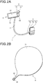
- the positioning sheet 6 includes, as depicted in FIG. 2B , a sheet-shaped fixing portion 31, a protrusion 32, and the magnet 33.
- the fixing portion 31 has a substantially circular shape with an enlarged diameter.
- the protrusion 32 protrudes to extend from an outer edge of the fixing portion 31.
- the magnet 33 is fixed and supported at a distal end of the protrusion 32. As depicted in FIG.
- the fixing portion 31 is disposed to expand between the helmet shell 102 and the inner part 103.
- the protrusion 32 is disposed to be exposed anteriorly from a space between the helmet shell 102 and the inner part 103.
- the fixing portion 31 has an enlarged diameter and a large frictional resistance surface. A friction force received by the fixing portion 31 from the helmet shell 102 and the inner part 103 causes the positioning sheet 6 to be fixed in a condition of being inserted inside the helmet main unit 101.
- the sheet-shaped fixing portion 31 under a condition of being sandwiched between the helmet shell 102 and the inner part 103, has a rear end 31a reaching a point near a head top portion 100a of the helmet 100 and, preferably, extending beyond the head top portion 100a of the helmet 100. Moving the inner part 103 away from the helmet shell 102 allows the fixing portion 31 to be moved. The position of the positioning sheet 6 can be adjusted freely with respect to the helmet 100.
- the monitor 2 When, from the condition depicted in FIG. 3 , the magnet 22 of the positioner 5 is attracted by the magnet 33 of the protrusion 32 disposed anterior to the helmet 100 as depicted in FIG. 1 , the monitor 2 is positioned correctly with respect to the helmet 100. Resisting an attraction force between the magnets 22 and 33 allows the positioner 5 to be removed from the positioning sheet 6, so that the positioner 5 can be removed from the positioning sheet 6.
- causing the clip 4 to pinch the helmet shell 102 allows the head-mounted display 1 to be mounted on the helmet 100.
- the user wears the helmet 100 and then flexes to adjust the position of the flexible hose 3 extending from the clip 4. These steps allow the monitor 2 to be disposed at a position before the eyes of the user. The user can thereby operate the saddle riding vehicle, while watching information, such as navigation, displayed on the monitor 2.
- the head-mounted display 1 in the present embodiment can be mounted by simply pinching the neck base 101b of the helmet 100 with the clip 4 and is thus mountable on the helmet 100 that can take various shapes.
- the mounting position of the head-mounted display 1 with respect to the helmet 100 can be freely adjusted by simply changing the position at which the neck base 101b is to be pinched.
- the head-mounted display 1 is configured so as to be mounted via the clip 4 and is thus readily mountable and removable with respect to the neck base 101b of the helmet 100.
- the monitor 2, because being mounted by way of the flexible hose 3, can be disposed at any position.
- the monitor 2 can thus be disposed at an optimum position within the field of view regardless of differences in the physique (e.g., size and shape of the face) and in an operating position for operating the saddle riding vehicle.
- the user attempts to remove the helmet 100, he or she displaces the monitor 2 laterally outwardly from an opening 101a in the helmet main unit 101. This makes removal of the user's helmet 100 easy without allowing the monitor 2 to be a hindrance.
- the clip 4 is configured so as to be removable with respect to the helmet shell 102.
- the clip 4 thus can be mounted and removed from the outside of the helmet 100, so that mounting of the helmet 100 on the head-mounted display 1 and removal of the helmet 100 from the head-mounted display 1 can be performed easily.
- the monitor 2 can be disposed inside a shield 104 of the helmet 100 by adjusting the position of the flexible hose 3.
- the shield 104 is a shield covering at least eyes of the user and is connected with the helmet shell 102 of the helmet 100 via a hinge 104a.
- the monitor 2 because being disposed inside the shield 104 of the helmet 100, can be protected by the shield 104 from air and obstacles.
- the monitor 2 can be disposed inside the shield 104. This arrangement allows a clearance between the shield 104 and the helmet main unit 101 to be narrowed and the function of the shield 104 is not likely to be impaired.
- the head-mounted display 1 in the present embodiment includes the positioner 5 and the positioning sheet 6 and the positioning sheet 6 is fixed to the helmet 100 at a freely adjustable position.
- the monitor 2 by adjusting the position of the protrusion 32 of the positioning sheet 6 to correspond to the physique of the user in advance, the monitor 2, when attempted to be positioned, can be more easily brought into a position optimum for the user.
- the monitor 2 is positioned at the helmet 100 through the positioner 5 and the positioning sheet 6.
- the monitor 2 can be prevented from being oscillated with respect to the helmet main unit 101 even with excessive vibrations, for example, under bad road conditions or in bad weather, or when the user shakes his or her head.
- the monitor 2 can thus be made more easily viewable. Additionally, the positioning sheet 6 is fixed to the helmet main unit 101. Because the monitor 2 is positioned at the helmet main unit 101 instead of the shield 104, the monitor 2 only can be left to stay within the field of view even when the shield 104 is rotated to swing up about the hinge 104a.
- the positioning sheet 6 is inserted and fixed between the helmet shell 102 and the inner part 103.
- the positioning sheet 6 can be fixed to the helmet main unit 101 through a simple structure.
- the positioning sheet 6 includes the fixing portion 31 having a diameter enlarged inside the helmet 100.
- the positioning sheet 6 can be fixed inside the helmet 100 by the increased frictional resistance surface with respect to the helmet shell 102 and the inner part 103, while having a compactly built protrusion 32 that protrudes to the outside of the helmet 100.
- the positioner 5 of the monitor 2 can be mounted on, and removed from, the positioning sheet 6.
- the monitor 2 can be removed from the positioning sheet 6 and displaced by flexing the flexible hose 3.
- the monitor 2 can thus be easily displaced to a position outside the field of view even with the head-mounted display 1 left attached to the helmet 100.
- the monitor 2 is positioned at the helmet main unit 101 instead of the shield 104 and, with the shield 104 in a lowered position, the positioner 5 can be removed from the positioning sheet 6 to thereby displace the monitor 2 to a position outside the field of view.
- the monitor 2 has been described to include the transmission-type liquid crystal display 11.
- a display configuration is nonetheless possible, in which, for example, a half mirror reflects a projected image and a real image anterior to the half mirror is transmitted to the field of view.
- the processor 12 including a battery and a processing unit has been described to be integrated, together with the liquid crystal display 11, with the frame 10.
- the processor 12 may nonetheless be separated from the monitor 2.
- an arrangement may be made to allow a cable to be disposed inside the flexible hose 3 and the cable inside the flexible hose 3 electrically connects the liquid crystal display 11 with an external processor 12 disposed on the clip 4 side.
- the clip 4 pinches the helmet 100 on the helmet shell 102 as a hat body from a steadiness viewpoint.
- the clip 4 may nonetheless pinch the helmet 100 on the inner part 103.
- the clip 4 may pinch the helmet 100 on both the helmet shell 102 and the inner part 103.
- the positioning sheet 6 has been described to be fixed inside the helmet 100 by the fixing portion 31 having an enlarged diameter.
- the positioning sheet 6 may nonetheless be fixed inside the helmet 100 by a clip instead of the fixing portion 31.
- the clip 4 has been described to include the torsion spring 4c.
- a configuration is still possible, in which the clip plates 4a and 4b removably pinch the helmet 100 using a wing nut and a bolt instead of the torsion spring 4c.
- a head-mounted display that can be mounted on a helmet which can take various shapes, that permits adjustments of a mounting position with respect to the helmet to any desired position, that facilitates mounting and removal, and that permits disposition of a display at any position.
- a head-mounted display includes a mounting portion 4 that can be removed from a helmet 100, a connector 3 that is connected with the mounting portion 4 and that allows a position to be freely adjusted.
- a display 2 is disposed at a distal end of the connector 3, the display 2 includes a positioner 5, and a positioned portion 6 at which the positioner 5 is positioned is fixed to the helmet 100 such that a position can be freely adjusted.
Landscapes
- Physics & Mathematics (AREA)
- General Physics & Mathematics (AREA)
- Optics & Photonics (AREA)
- Engineering & Computer Science (AREA)
- Multimedia (AREA)
- Signal Processing (AREA)
Abstract
Description
- The present invention relates to a head-mounted display that can be mounted on, and removed from, a helmet.
-
Patent Documents -
- [Patent Document 1]
Japanese Patent Laid-Open No.2009-092809 - [Patent Document 2]
Japanese Patent Laid-Open No.2002-072130 - With the arrangement disclosed in each of
Patent Documents - The present invention has been made in view of the foregoing situation and it is an object of the present invention to provide a head-mounted display that can be mounted on a helmet which can take various shapes, that permits adjustments of a mounting position with respect to a helmet to any desired position, that facilitates mounting and removal, and that permits disposition of a display at any position.
- To achieve the foregoing object, an aspect of the present invention provides a head-mounted display including a mounting portion (4) that can be removed from a helmet (100), a connector (3) that is connected with the mounting portion (4) and that allows a position to be freely adjusted, a display (2) disposed at a distal end of the connector (3), a positioner (5) included in the display (2), a positioned portion (6) at which the positioner (5) is positioned being fixed to the helmet (100) such that a position can be freely adjusted.
- In the aspect of the present invention, preferably, the positioned portion (6) is inserted and fixed in position between a helmet shell (102) and an inner part (103) .
- In the aspect of the present invention, preferably, the positioned portion (6) includes a fixing portion (31) having a diameter enlarged inside the helmet (100).
- In the aspect of the present invention, preferably, the positioner (5) is configured to be mountable on, and removable from, the positioned portion (6).
- In the aspect of the present invention, preferably, the display (2) includes a flat plate-shaped liquid crystal display (11).
- In the aspect of the present invention, preferably, the display (2) is provided so as to be disposed inside a shield (104) of the helmet (100).
- In the aspect of the present invention, preferably, the mounting portion (4) is removably disposed at the helmet shell (102) of the helmet (100).
- The head-mounted display in the aspect of the present invention includes a mounting portion that can be removed from a helmet, a connector that is connected with the mounting portion and that allows a position to be freely adjusted. A display is disposed at a distal end of the connector, the display includes a positioner, and a positioned portion at which the positioner is positioned is fixed to the helmet such that a position can be freely adjusted. Through the foregoing configuration, the head-mounted display can be mounted on a helmet that can take various shapes. The position of the head-mounted display can be freely adjusted with respect to a main unit of the helmet. Additionally, the head-mounted display facilitates mounting and removal. Additionally, the display can be disposed at any position. Thus, the display can be disposed at an optimum position within a field of view regardless of differences in physique (e.g., size and shape of a face of an occupant) and in an operating position for operating a vehicle. Removal of the helmet can also be easily performed by displacing the display outwardly. Additionally, the positioner and the positioned portion prevent the display from being oscillated by excessive vibrations (due to, for example, road conditions, weather, and when the occupant shakes his or her head). The display can thus be made more easily viewable. Because the display is positioned at the helmet main unit instead of a shield, the display only can be left to stay within the field of view even when the shield is raised.
- In the aspect of the present invention, the positioned portion may be inserted and fixed in position between the helmet shell and the inner part. Through the foregoing configuration, the positioned portion can be fixed to the helmet main unit using a simple structure.
- In the aspect of the present invention, the positioned portion may include the fixing portion having a diameter enlarged inside the helmet. Through the foregoing configuration, a frictional resistance surface between the helmet shell and the inner part can be increased, while having a compactly built protrusion that protrudes to the outside of the helmet.
- In the aspect of the present invention, the positioner is configured to be mountable on, and removable from, the positioned portion. Through the foregoing configuration, when the liquid crystal display is not necessary, the display can be easily displaced to a position outside the field of view. Moreover, by positioning the display in the helmet main unit instead of the shield, the display only can be displaced to a position outside the field of view with the shield in a lowered position.
- Additionally, in the aspect of the present invention, the display may include a flat plate-shaped liquid crystal display. Through the foregoing configuration, a displayed image is not curved and is thus easily recognizable.
- In the aspect of the present invention, the display may be provided so as to be disposed inside the shield of the helmet. Through the foregoing configuration, the display can be protected by the shield.
- In the aspect of the present invention, the mounting portion may be removably disposed at the helmet shell of the helmet. This configuration facilitates removal and wearing of the helmet.
-
- [
FIG. 1 ]
FIG. 1 is a view illustrating a head-mounted display according to an embodiment of the present invention mounted on a helmet. - [
FIG. 2 ]
FIGS. 2A and 2B are views illustrating the head-mounted display according to the embodiment of the present invention,FIG. 2A illustrating a main unit of the head-mounted display andFIG. 2B illustrating a positioning sheet. - [
FIG. 3 ]
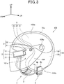
FIG. 3 is a view illustrating a condition in which a positioner has left the positioning sheet. - A specific embodiment to which the present invention is applied will be described below with reference to the accompanying drawings. Throughout the descriptions given hereunder, expressions indicating directions including front and rear, right and left, and up and down are identical to directions with reference to a user unless otherwise specified. In the drawings, an arrow FR indicates a direction anterior to the user, an arrow UP indicates a direction superior to the user, and an arrow LH indicates a direction toward the left of the user.
-
FIG. 1 is a perspective view of a head-mounteddisplay 1 according to an embodiment of the present invention mounted on ahelmet 100. - The head-mounted
display 1 is configured so as to be mounted on thehelmet 100 of an occupant of, for example, a saddle riding vehicle. The head-mounteddisplay 1 on thehelmet 100 is worn together with thehelmet 100 on a head. - The head-mounted
display 1 includes a monitor (display) 2, a flexible hose (connector) 3, and a clip (mounting portion) 4. Themonitor 2 displays information. Theflexible hose 3 supports themonitor 2. Theclip 4 mounts themonitor 2 on thehelmet 100 via theflexible hose 3. Theflexible hose 3 can maintain posture at a flexed position. - Reference is made to
FIG. 2A . Theclip 4 includes a pair ofclip plates flexible hose 3 has a first end connected with theclip plate 4a. Atorsion spring 4c is disposed between theclip plates - The
helmet 100 includes a helmetmain unit 101. The helmetmain unit 101 includes ahelmet shell 102 and aninner part 103 as a cushion. Theclip 4 is mounted at aneck base 101b of the helmetmain unit 101 such that theclip plate 4b is inserted between thehelmet shell 102 and theinner part 103. Theclip 4 can be mounted at any position of theneck base 101b. - The
monitor 2 is mounted on a second end of theflexible hose 3. Themonitor 2 includes aframe 10 and a transmission-type liquid crystal display (liquid crystal display) 11. Theliquid crystal display 11 is held in theframe 10. Theliquid crystal display 11 is formed into a flat plate shape (or flat sheet shape). Theliquid crystal display 11 having the flat sheet shape displays an easily visible image that is not curved. Theliquid crystal display 11, while displaying an information image generated by aprocessor 12, is configured such that a real image anterior to theliquid crystal display 11 can be transmitted toward a field of view. Theprocessor 12 includes an internal battery (not depicted), a communication unit (not depicted) capable of communicating with an external information processor (not depicted), and a processing unit (not depicted). On the basis of communication with the external information processor, theprocessor 12 controls theliquid crystal display 11 to thereby cause theliquid crystal display 11 to display information images including navigation, traveling speed, traveling spot, and the like. - The
frame 10 includes apositioner 5. Thepositioner 5 includes abulge 21 and amagnet 22. Thebulge 21 bulges outwardly from theframe 10. Themagnet 22 is fixed and supported at a distal end of thebulge 21. Themagnet 22 is attracted and fixed by amagnet 33 of a positioning sheet (positioned portion) 6. Thepositioning sheet 6 includes, as depicted inFIG. 2B , a sheet-shaped fixingportion 31, aprotrusion 32, and themagnet 33. The fixingportion 31 has a substantially circular shape with an enlarged diameter. Theprotrusion 32 protrudes to extend from an outer edge of the fixingportion 31. Themagnet 33 is fixed and supported at a distal end of theprotrusion 32. As depicted inFIG. 3 , the fixingportion 31 is disposed to expand between thehelmet shell 102 and theinner part 103. Theprotrusion 32 is disposed to be exposed anteriorly from a space between thehelmet shell 102 and theinner part 103. The fixingportion 31 has an enlarged diameter and a large frictional resistance surface. A friction force received by the fixingportion 31 from thehelmet shell 102 and theinner part 103 causes thepositioning sheet 6 to be fixed in a condition of being inserted inside the helmetmain unit 101. The sheet-shaped fixingportion 31, under a condition of being sandwiched between thehelmet shell 102 and theinner part 103, has arear end 31a reaching a point near a headtop portion 100a of thehelmet 100 and, preferably, extending beyond the headtop portion 100a of thehelmet 100. Moving theinner part 103 away from thehelmet shell 102 allows the fixingportion 31 to be moved. The position of thepositioning sheet 6 can be adjusted freely with respect to thehelmet 100. - When, from the condition depicted in
FIG. 3 , themagnet 22 of thepositioner 5 is attracted by themagnet 33 of theprotrusion 32 disposed anterior to thehelmet 100 as depicted inFIG. 1 , themonitor 2 is positioned correctly with respect to thehelmet 100. Resisting an attraction force between themagnets positioner 5 to be removed from thepositioning sheet 6, so that thepositioner 5 can be removed from thepositioning sheet 6. - In the head-mounted
display 1 according to the present embodiment, causing theclip 4 to pinch thehelmet shell 102 allows the head-mounteddisplay 1 to be mounted on thehelmet 100. The user wears thehelmet 100 and then flexes to adjust the position of theflexible hose 3 extending from theclip 4. These steps allow themonitor 2 to be disposed at a position before the eyes of the user. The user can thereby operate the saddle riding vehicle, while watching information, such as navigation, displayed on themonitor 2. - The head-mounted
display 1 in the present embodiment can be mounted by simply pinching theneck base 101b of thehelmet 100 with theclip 4 and is thus mountable on thehelmet 100 that can take various shapes. The mounting position of the head-mounteddisplay 1 with respect to thehelmet 100 can be freely adjusted by simply changing the position at which theneck base 101b is to be pinched. Furthermore, the head-mounteddisplay 1 is configured so as to be mounted via theclip 4 and is thus readily mountable and removable with respect to theneck base 101b of thehelmet 100. Themonitor 2, because being mounted by way of theflexible hose 3, can be disposed at any position. Themonitor 2 can thus be disposed at an optimum position within the field of view regardless of differences in the physique (e.g., size and shape of the face) and in an operating position for operating the saddle riding vehicle. In addition, when the user attempts to remove thehelmet 100, he or she displaces themonitor 2 laterally outwardly from anopening 101a in the helmetmain unit 101. This makes removal of the user'shelmet 100 easy without allowing themonitor 2 to be a hindrance. - The
clip 4 is configured so as to be removable with respect to thehelmet shell 102. Theclip 4 thus can be mounted and removed from the outside of thehelmet 100, so that mounting of thehelmet 100 on the head-mounteddisplay 1 and removal of thehelmet 100 from the head-mounteddisplay 1 can be performed easily. Additionally, as depicted inFIG. 1 , themonitor 2 can be disposed inside ashield 104 of thehelmet 100 by adjusting the position of theflexible hose 3. Theshield 104 is a shield covering at least eyes of the user and is connected with thehelmet shell 102 of thehelmet 100 via ahinge 104a. Themonitor 2, because being disposed inside theshield 104 of thehelmet 100, can be protected by theshield 104 from air and obstacles. - In the head-mounted
display 1 in the present embodiment, themonitor 2 can be disposed inside theshield 104. This arrangement allows a clearance between theshield 104 and the helmetmain unit 101 to be narrowed and the function of theshield 104 is not likely to be impaired. - The head-mounted
display 1 in the present embodiment includes thepositioner 5 and thepositioning sheet 6 and thepositioning sheet 6 is fixed to thehelmet 100 at a freely adjustable position. Thus, by adjusting the position of theprotrusion 32 of thepositioning sheet 6 to correspond to the physique of the user in advance, themonitor 2, when attempted to be positioned, can be more easily brought into a position optimum for the user. In addition, themonitor 2 is positioned at thehelmet 100 through thepositioner 5 and thepositioning sheet 6. As compared with an arrangement in which themonitor 2 is supported only by theflexible hose 3, themonitor 2 can be prevented from being oscillated with respect to the helmetmain unit 101 even with excessive vibrations, for example, under bad road conditions or in bad weather, or when the user shakes his or her head. Themonitor 2 can thus be made more easily viewable. Additionally, thepositioning sheet 6 is fixed to the helmetmain unit 101. Because themonitor 2 is positioned at the helmetmain unit 101 instead of theshield 104, themonitor 2 only can be left to stay within the field of view even when theshield 104 is rotated to swing up about thehinge 104a. - The
positioning sheet 6 is inserted and fixed between thehelmet shell 102 and theinner part 103. Thepositioning sheet 6 can be fixed to the helmetmain unit 101 through a simple structure. - The
positioning sheet 6 includes the fixingportion 31 having a diameter enlarged inside thehelmet 100. Thepositioning sheet 6 can be fixed inside thehelmet 100 by the increased frictional resistance surface with respect to thehelmet shell 102 and theinner part 103, while having a compactly builtprotrusion 32 that protrudes to the outside of thehelmet 100. - Additionally, the
positioner 5 of themonitor 2 can be mounted on, and removed from, thepositioning sheet 6. Thus, when navigation or other display is not necessary, themonitor 2 can be removed from thepositioning sheet 6 and displaced by flexing theflexible hose 3. Themonitor 2 can thus be easily displaced to a position outside the field of view even with the head-mounteddisplay 1 left attached to thehelmet 100. Moreover, themonitor 2 is positioned at the helmetmain unit 101 instead of theshield 104 and, with theshield 104 in a lowered position, thepositioner 5 can be removed from thepositioning sheet 6 to thereby displace themonitor 2 to a position outside the field of view. - The embodiment described above is illustrative only and not limiting and can be modified or applied freely within the spirit and scope of the invention.
- The
monitor 2 has been described to include the transmission-typeliquid crystal display 11. A display configuration is nonetheless possible, in which, for example, a half mirror reflects a projected image and a real image anterior to the half mirror is transmitted to the field of view. - The
processor 12 including a battery and a processing unit has been described to be integrated, together with theliquid crystal display 11, with theframe 10. Theprocessor 12 may nonetheless be separated from themonitor 2. For example, an arrangement may be made to allow a cable to be disposed inside theflexible hose 3 and the cable inside theflexible hose 3 electrically connects theliquid crystal display 11 with anexternal processor 12 disposed on theclip 4 side. - Additionally, preferably, the
clip 4 pinches thehelmet 100 on thehelmet shell 102 as a hat body from a steadiness viewpoint. Theclip 4 may nonetheless pinch thehelmet 100 on theinner part 103. Alternatively, theclip 4 may pinch thehelmet 100 on both thehelmet shell 102 and theinner part 103. - The
positioning sheet 6 has been described to be fixed inside thehelmet 100 by the fixingportion 31 having an enlarged diameter. Thepositioning sheet 6 may nonetheless be fixed inside thehelmet 100 by a clip instead of the fixingportion 31. - Additionally, the
clip 4 has been described to include thetorsion spring 4c. A configuration is still possible, in which theclip plates helmet 100 using a wing nut and a bolt instead of thetorsion spring 4c. - To provide a head-mounted display that can be mounted on a helmet which can take various shapes, that permits adjustments of a mounting position with respect to the helmet to any desired position, that facilitates mounting and removal, and that permits disposition of a display at any position.
- A head-mounted display includes a mounting
portion 4 that can be removed from ahelmet 100, aconnector 3 that is connected with the mountingportion 4 and that allows a position to be freely adjusted. Adisplay 2 is disposed at a distal end of theconnector 3, thedisplay 2 includes apositioner 5, and a positionedportion 6 at which thepositioner 5 is positioned is fixed to thehelmet 100 such that a position can be freely adjusted. -
- 2 Display
- 3 Connector
- 4 Mounting portion
- 5 Positioner
- 6 Positioned portion
- 11 Liquid crystal display
- 100 Helmet
- 102 Helmet shell
- 103 Inner part
- 104 Shield
Claims (7)
- A head-mounted display characterized by comprising:a mounting portion (4) that can be removed from a helmet (100);a connector (3) connected with the mounting portion (4) and allowing a position to be freely adjusted;a display (2) disposed at a distal end of the connector (3);a positioner (5) included in the display (2);a positioned portion (6) at which the positioner (5) is positioned being fixed to the helmet (100) such that a position can be freely adjusted.
- The head-mounted display according to claim 1, wherein the positioned portion (6) is inserted and fixed in position between a helmet shell (102) and an inner part (103).
- The head-mounted display according to claim 1 or 2, wherein the positioned portion (6) includes a fixing portion (31) having a diameter enlarged inside the helmet (100) .
- The head-mounted display according to any one of claims 1 to 3, wherein the positioner (5) can be mounted on, and removed from, the positioned portion (6).
- The head-mounted display according to any one of claims 1 to 4, wherein the display (2) includes a flat plate-shaped liquid crystal display (11).
- The head-mounted display according to any one of claims 1 to 5, wherein the display (2) is provided so as to be disposed inside a shield (104) of the helmet (100).
- The head-mounted display according to any one of claims 1 to 6, wherein the mounting portion (4) is removably disposed at the helmet shell (102) of the helmet (100).
Applications Claiming Priority (1)
| Application Number | Priority Date | Filing Date | Title |
|---|---|---|---|
| JP2017061766A JP6502989B2 (en) | 2017-03-27 | 2017-03-27 | Head mounted display |
Publications (2)
| Publication Number | Publication Date |
|---|---|
| EP3381310A1 true EP3381310A1 (en) | 2018-10-03 |
| EP3381310B1 EP3381310B1 (en) | 2019-10-23 |
Family
ID=61563273
Family Applications (1)
| Application Number | Title | Priority Date | Filing Date |
|---|---|---|---|
| EP18159916.8A Active EP3381310B1 (en) | 2017-03-27 | 2018-03-05 | Head-mounted display |
Country Status (3)
| Country | Link |
|---|---|
| US (1) | US10488669B2 (en) |
| EP (1) | EP3381310B1 (en) |
| JP (1) | JP6502989B2 (en) |
Families Citing this family (1)
| Publication number | Priority date | Publication date | Assignee | Title |
|---|---|---|---|---|
| US12250361B2 (en) | 2022-08-18 | 2025-03-11 | Apple Inc. | Optical assemblies for shared experience |
Citations (6)
| Publication number | Priority date | Publication date | Assignee | Title |
|---|---|---|---|---|
| JP2002072130A (en) | 2000-08-29 | 2002-03-12 | Shimadzu Corp | Head-mounted information display device |
| JP2009092809A (en) | 2007-10-05 | 2009-04-30 | Nikon Corp | Head mounted display device |
| US20130305437A1 (en) * | 2012-05-19 | 2013-11-21 | Skully Helmets Inc. | Augmented reality motorcycle helmet |
| WO2015127896A1 (en) * | 2014-02-26 | 2015-09-03 | 王浩 | Helmet-type thermal imaging apparatus |
| WO2016022984A1 (en) * | 2014-08-08 | 2016-02-11 | Fusar Technologies, Inc. | Helmet system and methods |
| US20160227866A1 (en) * | 2015-02-05 | 2016-08-11 | Amit TAL | Helmet with monocular optical display |
Family Cites Families (13)
| Publication number | Priority date | Publication date | Assignee | Title |
|---|---|---|---|---|
| JP4572737B2 (en) * | 2005-05-10 | 2010-11-04 | 株式会社島津製作所 | Head mounted display |
| JP4622937B2 (en) * | 2006-06-14 | 2011-02-02 | 株式会社島津製作所 | Head-mounted display device |
| US9217868B2 (en) * | 2007-01-12 | 2015-12-22 | Kopin Corporation | Monocular display device |
| JP2010124339A (en) * | 2008-11-20 | 2010-06-03 | Scalar Corp | Head-mounted display |
| US20130278631A1 (en) * | 2010-02-28 | 2013-10-24 | Osterhout Group, Inc. | 3d positioning of augmented reality information |
| US20130083003A1 (en) * | 2011-09-30 | 2013-04-04 | Kathryn Stone Perez | Personal audio/visual system |
| US9904053B2 (en) * | 2014-12-25 | 2018-02-27 | Seiko Epson Corporation | Display device, and method of controlling display device |
| US9794684B2 (en) * | 2015-02-13 | 2017-10-17 | Seiko Epson Corporation | Head-mounted display device, control method for the same, and computer program |
| WO2016162901A1 (en) * | 2015-04-07 | 2016-10-13 | オリンパス株式会社 | Eyeglasses-type display apparatus |
| JP2017022668A (en) * | 2015-07-15 | 2017-01-26 | コニカミノルタ株式会社 | Wearable display |
| KR102524322B1 (en) * | 2015-09-25 | 2023-04-24 | 삼성전자주식회사 | Band connecting device and head-mounted display apparatus having the same |
| US10888228B2 (en) * | 2016-11-10 | 2021-01-12 | SK Commercial Construction, Inc. | Method and system for correlating anatomy using an electronic mobile device transparent display screen |
| US20180365900A1 (en) * | 2017-06-20 | 2018-12-20 | Immerex Inc. | Mixed Reality Head Mounted Display Device |
-
2017
- 2017-03-27 JP JP2017061766A patent/JP6502989B2/en active Active
-
2018
- 2018-02-28 US US15/908,032 patent/US10488669B2/en active Active
- 2018-03-05 EP EP18159916.8A patent/EP3381310B1/en active Active
Patent Citations (6)
| Publication number | Priority date | Publication date | Assignee | Title |
|---|---|---|---|---|
| JP2002072130A (en) | 2000-08-29 | 2002-03-12 | Shimadzu Corp | Head-mounted information display device |
| JP2009092809A (en) | 2007-10-05 | 2009-04-30 | Nikon Corp | Head mounted display device |
| US20130305437A1 (en) * | 2012-05-19 | 2013-11-21 | Skully Helmets Inc. | Augmented reality motorcycle helmet |
| WO2015127896A1 (en) * | 2014-02-26 | 2015-09-03 | 王浩 | Helmet-type thermal imaging apparatus |
| WO2016022984A1 (en) * | 2014-08-08 | 2016-02-11 | Fusar Technologies, Inc. | Helmet system and methods |
| US20160227866A1 (en) * | 2015-02-05 | 2016-08-11 | Amit TAL | Helmet with monocular optical display |
Also Published As
| Publication number | Publication date |
|---|---|
| JP2018164237A (en) | 2018-10-18 |
| EP3381310B1 (en) | 2019-10-23 |
| US10488669B2 (en) | 2019-11-26 |
| JP6502989B2 (en) | 2019-04-17 |
| US20180275413A1 (en) | 2018-09-27 |
Similar Documents
| Publication | Publication Date | Title |
|---|---|---|
| WO2007129661A1 (en) | Head mount display | |
| US6034653A (en) | Head-set display device | |
| US11262589B2 (en) | Positioning and stabilising structure and system incorporating same | |
| US9039169B2 (en) | Support member for wearable instrument and head-mounted wearable device | |
| JP7277099B2 (en) | Head-mounted displays, dimming materials | |
| JP2022040920A (en) | Head mounted display | |
| CN109073890A (en) | Aircraft head-mounted visualization system with buckles compatible with audio headsets | |
| EP3381310B1 (en) | Head-mounted display | |
| US11347059B2 (en) | Head mounted apparatus | |
| US20220244549A1 (en) | Attachment and head-mounted display | |
| US10502960B2 (en) | Information display assembly | |
| JP2018136369A (en) | Head mounted display | |
| JP2016191950A (en) | Virtual image display device | |
| JP2014007513A (en) | Electronic apparatus | |
| JP2009260798A (en) | Mounting attachment for optical equipment | |
| JP2018132706A (en) | Attitude maintenance tool for spectacle frame shape holding member | |
| JPH1039246A5 (en) | ||
| JP2008271054A (en) | Body-mounted display | |
| JP2005277497A (en) | Head-mounted display device | |
| US20250147324A1 (en) | Wearable video display | |
| JP6116745B1 (en) | Virtual image display device, portable terminal, display control method, and display control program | |
| JPH06281879A (en) | Head mounted display device | |
| JP2004207847A (en) | Display device | |
| EP4127817A1 (en) | Positioning and stabilising structure and system incorporating same | |
| CN117555136A (en) | Shoulder support type AR head display device |
Legal Events
| Date | Code | Title | Description |
|---|---|---|---|
| PUAI | Public reference made under article 153(3) epc to a published international application that has entered the european phase |
Free format text: ORIGINAL CODE: 0009012 |
|
| STAA | Information on the status of an ep patent application or granted ep patent |
Free format text: STATUS: REQUEST FOR EXAMINATION WAS MADE |
|
| 17P | Request for examination filed |
Effective date: 20180305 |
|
| AK | Designated contracting states |
Kind code of ref document: A1 Designated state(s): AL AT BE BG CH CY CZ DE DK EE ES FI FR GB GR HR HU IE IS IT LI LT LU LV MC MK MT NL NO PL PT RO RS SE SI SK SM TR |
|
| AX | Request for extension of the european patent |
Extension state: BA ME |
|
| GRAP | Despatch of communication of intention to grant a patent |
Free format text: ORIGINAL CODE: EPIDOSNIGR1 |
|
| RIC1 | Information provided on ipc code assigned before grant |
Ipc: A42B 3/04 20060101AFI20190408BHEP Ipc: G02B 27/01 20060101ALI20190408BHEP |
|
| STAA | Information on the status of an ep patent application or granted ep patent |
Free format text: STATUS: GRANT OF PATENT IS INTENDED |
|
| INTG | Intention to grant announced |
Effective date: 20190516 |
|
| GRAS | Grant fee paid |
Free format text: ORIGINAL CODE: EPIDOSNIGR3 |
|
| GRAA | (expected) grant |
Free format text: ORIGINAL CODE: 0009210 |
|
| STAA | Information on the status of an ep patent application or granted ep patent |
Free format text: STATUS: THE PATENT HAS BEEN GRANTED |
|
| AK | Designated contracting states |
Kind code of ref document: B1 Designated state(s): AL AT BE BG CH CY CZ DE DK EE ES FI FR GB GR HR HU IE IS IT LI LT LU LV MC MK MT NL NO PL PT RO RS SE SI SK SM TR |
|
| REG | Reference to a national code |
Ref country code: GB Ref legal event code: FG4D |
|
| REG | Reference to a national code |
Ref country code: CH Ref legal event code: EP |
|
| REG | Reference to a national code |
Ref country code: IE Ref legal event code: FG4D |
|
| REG | Reference to a national code |
Ref country code: DE Ref legal event code: R096 Ref document number: 602018000932 Country of ref document: DE |
|
| REG | Reference to a national code |
Ref country code: AT Ref legal event code: REF Ref document number: 1192678 Country of ref document: AT Kind code of ref document: T Effective date: 20191115 |
|
| REG | Reference to a national code |
Ref country code: NL Ref legal event code: MP Effective date: 20191023 |
|
| REG | Reference to a national code |
Ref country code: LT Ref legal event code: MG4D |
|
| PG25 | Lapsed in a contracting state [announced via postgrant information from national office to epo] |
Ref country code: NO Free format text: LAPSE BECAUSE OF FAILURE TO SUBMIT A TRANSLATION OF THE DESCRIPTION OR TO PAY THE FEE WITHIN THE PRESCRIBED TIME-LIMIT Effective date: 20200123 Ref country code: GR Free format text: LAPSE BECAUSE OF FAILURE TO SUBMIT A TRANSLATION OF THE DESCRIPTION OR TO PAY THE FEE WITHIN THE PRESCRIBED TIME-LIMIT Effective date: 20200124 Ref country code: PL Free format text: LAPSE BECAUSE OF FAILURE TO SUBMIT A TRANSLATION OF THE DESCRIPTION OR TO PAY THE FEE WITHIN THE PRESCRIBED TIME-LIMIT Effective date: 20191023 Ref country code: LT Free format text: LAPSE BECAUSE OF FAILURE TO SUBMIT A TRANSLATION OF THE DESCRIPTION OR TO PAY THE FEE WITHIN THE PRESCRIBED TIME-LIMIT Effective date: 20191023 Ref country code: NL Free format text: LAPSE BECAUSE OF FAILURE TO SUBMIT A TRANSLATION OF THE DESCRIPTION OR TO PAY THE FEE WITHIN THE PRESCRIBED TIME-LIMIT Effective date: 20191023 Ref country code: SE Free format text: LAPSE BECAUSE OF FAILURE TO SUBMIT A TRANSLATION OF THE DESCRIPTION OR TO PAY THE FEE WITHIN THE PRESCRIBED TIME-LIMIT Effective date: 20191023 Ref country code: LV Free format text: LAPSE BECAUSE OF FAILURE TO SUBMIT A TRANSLATION OF THE DESCRIPTION OR TO PAY THE FEE WITHIN THE PRESCRIBED TIME-LIMIT Effective date: 20191023 Ref country code: BG Free format text: LAPSE BECAUSE OF FAILURE TO SUBMIT A TRANSLATION OF THE DESCRIPTION OR TO PAY THE FEE WITHIN THE PRESCRIBED TIME-LIMIT Effective date: 20200123 Ref country code: FI Free format text: LAPSE BECAUSE OF FAILURE TO SUBMIT A TRANSLATION OF THE DESCRIPTION OR TO PAY THE FEE WITHIN THE PRESCRIBED TIME-LIMIT Effective date: 20191023 Ref country code: PT Free format text: LAPSE BECAUSE OF FAILURE TO SUBMIT A TRANSLATION OF THE DESCRIPTION OR TO PAY THE FEE WITHIN THE PRESCRIBED TIME-LIMIT Effective date: 20200224 |
|
| PG25 | Lapsed in a contracting state [announced via postgrant information from national office to epo] |
Ref country code: RS Free format text: LAPSE BECAUSE OF FAILURE TO SUBMIT A TRANSLATION OF THE DESCRIPTION OR TO PAY THE FEE WITHIN THE PRESCRIBED TIME-LIMIT Effective date: 20191023 Ref country code: IS Free format text: LAPSE BECAUSE OF FAILURE TO SUBMIT A TRANSLATION OF THE DESCRIPTION OR TO PAY THE FEE WITHIN THE PRESCRIBED TIME-LIMIT Effective date: 20200224 Ref country code: HR Free format text: LAPSE BECAUSE OF FAILURE TO SUBMIT A TRANSLATION OF THE DESCRIPTION OR TO PAY THE FEE WITHIN THE PRESCRIBED TIME-LIMIT Effective date: 20191023 |
|
| PG25 | Lapsed in a contracting state [announced via postgrant information from national office to epo] |
Ref country code: AL Free format text: LAPSE BECAUSE OF FAILURE TO SUBMIT A TRANSLATION OF THE DESCRIPTION OR TO PAY THE FEE WITHIN THE PRESCRIBED TIME-LIMIT Effective date: 20191023 |
|
| REG | Reference to a national code |
Ref country code: DE Ref legal event code: R097 Ref document number: 602018000932 Country of ref document: DE |
|
| PG2D | Information on lapse in contracting state deleted |
Ref country code: IS |
|
| PG25 | Lapsed in a contracting state [announced via postgrant information from national office to epo] |
Ref country code: DK Free format text: LAPSE BECAUSE OF FAILURE TO SUBMIT A TRANSLATION OF THE DESCRIPTION OR TO PAY THE FEE WITHIN THE PRESCRIBED TIME-LIMIT Effective date: 20191023 Ref country code: EE Free format text: LAPSE BECAUSE OF FAILURE TO SUBMIT A TRANSLATION OF THE DESCRIPTION OR TO PAY THE FEE WITHIN THE PRESCRIBED TIME-LIMIT Effective date: 20191023 Ref country code: CZ Free format text: LAPSE BECAUSE OF FAILURE TO SUBMIT A TRANSLATION OF THE DESCRIPTION OR TO PAY THE FEE WITHIN THE PRESCRIBED TIME-LIMIT Effective date: 20191023 Ref country code: ES Free format text: LAPSE BECAUSE OF FAILURE TO SUBMIT A TRANSLATION OF THE DESCRIPTION OR TO PAY THE FEE WITHIN THE PRESCRIBED TIME-LIMIT Effective date: 20191023 Ref country code: RO Free format text: LAPSE BECAUSE OF FAILURE TO SUBMIT A TRANSLATION OF THE DESCRIPTION OR TO PAY THE FEE WITHIN THE PRESCRIBED TIME-LIMIT Effective date: 20191023 Ref country code: IS Free format text: LAPSE BECAUSE OF FAILURE TO SUBMIT A TRANSLATION OF THE DESCRIPTION OR TO PAY THE FEE WITHIN THE PRESCRIBED TIME-LIMIT Effective date: 20200223 |
|
| REG | Reference to a national code |
Ref country code: AT Ref legal event code: MK05 Ref document number: 1192678 Country of ref document: AT Kind code of ref document: T Effective date: 20191023 |
|
| PLBE | No opposition filed within time limit |
Free format text: ORIGINAL CODE: 0009261 |
|
| STAA | Information on the status of an ep patent application or granted ep patent |
Free format text: STATUS: NO OPPOSITION FILED WITHIN TIME LIMIT |
|
| PG25 | Lapsed in a contracting state [announced via postgrant information from national office to epo] |
Ref country code: SM Free format text: LAPSE BECAUSE OF FAILURE TO SUBMIT A TRANSLATION OF THE DESCRIPTION OR TO PAY THE FEE WITHIN THE PRESCRIBED TIME-LIMIT Effective date: 20191023 Ref country code: SK Free format text: LAPSE BECAUSE OF FAILURE TO SUBMIT A TRANSLATION OF THE DESCRIPTION OR TO PAY THE FEE WITHIN THE PRESCRIBED TIME-LIMIT Effective date: 20191023 |
|
| 26N | No opposition filed |
Effective date: 20200724 |
|
| PG25 | Lapsed in a contracting state [announced via postgrant information from national office to epo] |
Ref country code: MC Free format text: LAPSE BECAUSE OF FAILURE TO SUBMIT A TRANSLATION OF THE DESCRIPTION OR TO PAY THE FEE WITHIN THE PRESCRIBED TIME-LIMIT Effective date: 20191023 |
|
| PG25 | Lapsed in a contracting state [announced via postgrant information from national office to epo] |
Ref country code: SI Free format text: LAPSE BECAUSE OF FAILURE TO SUBMIT A TRANSLATION OF THE DESCRIPTION OR TO PAY THE FEE WITHIN THE PRESCRIBED TIME-LIMIT Effective date: 20191023 Ref country code: AT Free format text: LAPSE BECAUSE OF FAILURE TO SUBMIT A TRANSLATION OF THE DESCRIPTION OR TO PAY THE FEE WITHIN THE PRESCRIBED TIME-LIMIT Effective date: 20191023 |
|
| REG | Reference to a national code |
Ref country code: BE Ref legal event code: MM Effective date: 20200331 |
|
| PG25 | Lapsed in a contracting state [announced via postgrant information from national office to epo] |
Ref country code: LU Free format text: LAPSE BECAUSE OF NON-PAYMENT OF DUE FEES Effective date: 20200305 |
|
| PG25 | Lapsed in a contracting state [announced via postgrant information from national office to epo] |
Ref country code: IE Free format text: LAPSE BECAUSE OF NON-PAYMENT OF DUE FEES Effective date: 20200305 Ref country code: FR Free format text: LAPSE BECAUSE OF NON-PAYMENT OF DUE FEES Effective date: 20200331 |
|
| PG25 | Lapsed in a contracting state [announced via postgrant information from national office to epo] |
Ref country code: BE Free format text: LAPSE BECAUSE OF NON-PAYMENT OF DUE FEES Effective date: 20200331 |
|
| PGFP | Annual fee paid to national office [announced via postgrant information from national office to epo] |
Ref country code: IT Payment date: 20210331 Year of fee payment: 4 |
|
| REG | Reference to a national code |
Ref country code: DE Ref legal event code: R084 Ref document number: 602018000932 Country of ref document: DE |
|
| REG | Reference to a national code |
Ref country code: CH Ref legal event code: PL |
|
| PG25 | Lapsed in a contracting state [announced via postgrant information from national office to epo] |
Ref country code: CH Free format text: LAPSE BECAUSE OF NON-PAYMENT OF DUE FEES Effective date: 20210331 Ref country code: LI Free format text: LAPSE BECAUSE OF NON-PAYMENT OF DUE FEES Effective date: 20210331 |
|
| PG25 | Lapsed in a contracting state [announced via postgrant information from national office to epo] |
Ref country code: TR Free format text: LAPSE BECAUSE OF FAILURE TO SUBMIT A TRANSLATION OF THE DESCRIPTION OR TO PAY THE FEE WITHIN THE PRESCRIBED TIME-LIMIT Effective date: 20191023 Ref country code: MT Free format text: LAPSE BECAUSE OF FAILURE TO SUBMIT A TRANSLATION OF THE DESCRIPTION OR TO PAY THE FEE WITHIN THE PRESCRIBED TIME-LIMIT Effective date: 20191023 Ref country code: CY Free format text: LAPSE BECAUSE OF FAILURE TO SUBMIT A TRANSLATION OF THE DESCRIPTION OR TO PAY THE FEE WITHIN THE PRESCRIBED TIME-LIMIT Effective date: 20191023 |
|
| PG25 | Lapsed in a contracting state [announced via postgrant information from national office to epo] |
Ref country code: MK Free format text: LAPSE BECAUSE OF FAILURE TO SUBMIT A TRANSLATION OF THE DESCRIPTION OR TO PAY THE FEE WITHIN THE PRESCRIBED TIME-LIMIT Effective date: 20191023 |
|
| GBPC | Gb: european patent ceased through non-payment of renewal fee |
Effective date: 20220305 |
|
| PG25 | Lapsed in a contracting state [announced via postgrant information from national office to epo] |
Ref country code: GB Free format text: LAPSE BECAUSE OF NON-PAYMENT OF DUE FEES Effective date: 20220305 |
|
| PG25 | Lapsed in a contracting state [announced via postgrant information from national office to epo] |
Ref country code: IT Free format text: LAPSE BECAUSE OF NON-PAYMENT OF DUE FEES Effective date: 20220305 |
|
| PGFP | Annual fee paid to national office [announced via postgrant information from national office to epo] |
Ref country code: DE Payment date: 20260219 Year of fee payment: 9 |