EP3381251B1 - Gartengerät zur bodenbearbeitung und saat- bzw. pflanzenverfahren mit hilfe eines solchen gartengeräts - Google Patents
Gartengerät zur bodenbearbeitung und saat- bzw. pflanzenverfahren mit hilfe eines solchen gartengeräts Download PDFInfo
- Publication number
- EP3381251B1 EP3381251B1 EP18020110.5A EP18020110A EP3381251B1 EP 3381251 B1 EP3381251 B1 EP 3381251B1 EP 18020110 A EP18020110 A EP 18020110A EP 3381251 B1 EP3381251 B1 EP 3381251B1
- Authority
- EP
- European Patent Office
- Prior art keywords
- soil
- garden
- moisture
- nutrient content
- electrodes
- Prior art date
- Legal status (The legal status is an assumption and is not a legal conclusion. Google has not performed a legal analysis and makes no representation as to the accuracy of the status listed.)
- Active
Links
Images




Classifications
-
- A—HUMAN NECESSITIES
- A01—AGRICULTURE; FORESTRY; ANIMAL HUSBANDRY; HUNTING; TRAPPING; FISHING
- A01B—SOIL WORKING IN AGRICULTURE OR FORESTRY; PARTS, DETAILS, OR ACCESSORIES OF AGRICULTURAL MACHINES OR IMPLEMENTS, IN GENERAL
- A01B1/00—Hand tools
- A01B1/02—Spades; Shovels
-
- A—HUMAN NECESSITIES
- A01—AGRICULTURE; FORESTRY; ANIMAL HUSBANDRY; HUNTING; TRAPPING; FISHING
- A01C—PLANTING; SOWING; FERTILISING
- A01C21/00—Methods of fertilising, sowing or planting
- A01C21/007—Determining fertilization requirements
-
- A—HUMAN NECESSITIES
- A01—AGRICULTURE; FORESTRY; ANIMAL HUSBANDRY; HUNTING; TRAPPING; FISHING
- A01B—SOIL WORKING IN AGRICULTURE OR FORESTRY; PARTS, DETAILS, OR ACCESSORIES OF AGRICULTURAL MACHINES OR IMPLEMENTS, IN GENERAL
- A01B79/00—Methods for working soil
- A01B79/005—Precision agriculture
Definitions
- the invention relates to a garden implement for soil cultivation according to the preamble of claim 1, as well as a seed or planting method carried out with the aid of such a garden implement.
- the trend is therefore to integrate the sensors already in the devices to be used by the gardener.
- the international patent application discloses WO 2016 118 000 A1 a fertilizer application device that can pierce holes in the soil and then introduce the fertilizer into it.
- the unit includes a temperature and a pH sensor to determine the temperature or pH of the soil before placing the fertilizer in the soil.
- a fertilizer application device is very expensive for horticultural use outside of industrial agriculture and is too specific in its actual application for the probes used to be able to exploit their full benefits.
- the Canadian patent application CA 2 836 642 A1 shows a garden shovel with a moisture and a nitrate content sensor on the blade.
- the blade handle while a display is provided.
- the blade has a microchip, which can forward the measurement results to remote devices such as computers or mobile phones.
- the nitrate sensor is embedded in a silicate membrane and is located behind the blade, diphenylamine reacts with nitrate particles in the silicate membrane and thereby turns blue and the sensor performs a spectrophotometric detection of the coloration and thus the nitrate amount.
- the moisture sensor is located on the front of the blade and consists of microscopic plates with a variety of water sensitive discs that swell when in contact with water and contact an actuator when reaching a critical length, which emits a signal corresponding to the recorded amount of water.
- the gardening tool according to the invention for tillage has a handle portion and a ground contact portion attached thereto.
- the gardening tool is designed as a garden blade, so that the ground contact portion has the shape of an airfoil.
- the garden device according to the invention comprises a power supply, a moisture detection device for detecting a number of soil moisture corresponding sizes, a nutrient detection device for detecting a number of nutrient content in the soil corresponding sizes, a computing unit for calculating the soil moisture from the soil moisture corresponding number of sizes and the nutrient content the sizes corresponding to the nutrient content, as well as an output device for outputting the soil moisture and / or based on the soil moisture information and for outputting the nutrient content in the soil and / or based on the nutrient content information.
- the garden implement according to the invention is characterized, on the one hand, by the fact that the moisture detection device has two first electrodes mounted on the bottom contact section in the manner of a plate capacitor such that a capacitance of the plate capacitor is influenced by earth as a dielectric when the earth is in contact with the ground contact section is contacted between the electrodes. This achieves a cost-effective, but reliable working structure of the moisture detection device.
- the gardening tool has a user interface, a selection program of user-selectable garden plants and / or vegetables, in the favorable soil moisture or nutrient content in the Floor for the garden plants and / or vegetables are stored, and a comparator, which compares the deposited target values for the selected garden plant or vegetable with the recorded actual soil moisture and / or nutrient content in the soil and transmits the result for output on the output device. It is thus possible to indicate directly whether the determined soil moisture and the determined nutrient content are suitable for a particular plant.
- the sowing or planting method comprises the following steps: Determination of a favorable garden soil or nutrient content in the soil for a particular garden plant or vegetable species to be sown or planted, at a site intended for sowing or planting, determining an actual soil moisture and nutrient content in the soil, then comparing the respective soil Setpoint with the respective actual value and, if the comparison is positive, sowing or planting the garden plant or vegetable species, wherein the determination of the actual and target values for the soil moisture and the nutrient content in the soil is carried out with the aid of the garden implement according to the invention, which on the for sowing or planting intended place in the soil is inserted and which can serve then in the positive comparison case equal to the creation of the hole for the seed or the plant with the sowing or with plants.
- the arithmetic unit is set up to calculate an output variable representing the soil moisture from the capacitance of the plate capacitor and / or from a variable derived from the capacitance of the plate capacitor as an input variable.
- the arithmetic unit may include a stored in their memory lookup table or the like, from which the context.
- the moisture detection device therefore has a vibration generator connected in series with the plate capacitor to form an oscillator circuit.
- the oscillator circuit can easily be evaluated if it outputs binary output signals as a tilting oscillator.
- the vibration generator can be designed as a Schmitt trigger. The frequency of the vibration generated by contact with the earth can then be supplied instead of or in addition to the capacity of the plate capacitor of the arithmetic unit as an input to the soil moisture.
- the ground contact portion on which the electrodes are applied consists of a non-conductive and preferably good dielectric material.
- the ground contact portion consists of plastic, on the surface of which the electrodes can be applied, so that they can be brought into contact with the ground or the earth. It would also be conceivable to form only parts of the airfoil or of the ground contact section made of plastic. More preferably, however, when the ground contact portion is made entirely of fiber-reinforced plastic, in particular glass fiber reinforced plastic is well suited, since this acts in addition to a high strength and Abriebarmut even strong dielectric.
- the electrodes of the moisture detection device can then advantageously consist of a conductive material such as copper or a copper alloy and against the environment air-tight and moisture-tight sealed be applied to the ground contact portion. Therefore, the electrodes are not only inexpensive to produce, but also protected against corrosion or oxidation, so that the electrode material does not require expensive surface treatment or must consist of expensive elements or alloys.
- the seal also prevents the electrodes from coming into direct contact with the ground, thus avoiding unwanted current flow. It would also be possible to apply the two electrodes offset from each other on the front and back of the blade or the ground contact portion. However, it would also be conceivable to embed the electrodes in the interior of the plastic or even to weave them into the fabric of the fiber reinforcement.
- the ground contact portion is also replaceable and in particular mounted without tools replaceable on the handle portion, for example via a bayonet closure or the well-known from the garden area connectors, e.g. from the company Gardena.
- the electrical contacting of the electrodes could be provided an additional connector or the like.
- the airfoil or ground contact portion configured as another work tool can then be easily replaced when worn without having to renew the handle portion containing the electronics.
- the handle portion advantageously comprises a handle, in which a microcontroller of the computing unit and a number of batteries of the power supply are housed, for. B. a 9-V block or a rechargeable battery, wherein on the stem an on / off switch and preferably also a display of the output device is arranged.
- the handle portion has at its end facing away from the bottom contact portion on a removable cap over which a battery receiving compartment in the interior of the stem is accessible, so that the battery can be removed or replaced when it is discharged.
- the connection of the closure cap with the handle portion is advantageously carried out watertight, so that no dirt or water can get into the interior of the battery compartment.
- a rechargeable accumulator could be provided as a battery, wherein the garden implement at its handle portion and there preferably at its end facing away from the bottom contact portion has a corresponding connection socket for a charger.
- a contactless battery charging system in particular an inductive charging system in the manner of an electric toothbrush, so that then the battery could be permanently installed and sealed inside the handle.
- the gardening tool has a plurality of differently shaped ground contacting portions provided with the two first electrodes and adapted to the handle portion.
- the gardening tool can then be used for versatile purposes.
- one of the ground contact portions could be formed as an airfoil, another ground contact portion as a trowel, and another ground contact portion as a hoe, etc.
- the nutrient detection device can be constructed so that it detects an electrical conductivity of the soil as a measure of the nutrient content.
- it may comprise two spaced-apart on the ground contact portion of the garden implement or, if present, mounted on each of the different ground contact portions, further electrodes.
- the electrical conductivity of the soil which is the greater the more nutrient ions are in the soil and therefore provides a measure of the nutrient content of the soil.
- the two first electrodes are advantageously located locally between the two further electrodes of the nutrient detection device, so that they can be arranged so close together that they can form a plate capacitor, whereas the removal of the two other electrodes of the nutrient detection device, which indeed a current flow between them should allow to be further apart from each other.
- the two further electrodes can therefore consist of chemical nickel or comprise a layer of chemical nickel.
- the nickel layer is covered with a gold layer, which not only prevents the oxidation of the nickel, but can also produce a good conductive contact with the soil.
- the two further electrodes are therefore particularly preferably made of chemically nickel / buff gold.
- the nickel layer may be, for example, between 4 and 7 microns thick, the attached gold layer between 0.05 and 0.1 microns.
- the purpose of the gold layer is also to prevent the electrodes, ie the nickel, from decomposing, releasing poisonous ions for the plants.
- the electrodes consist of a thin layer of graphite, palladium, ridium, gold, platinum or similar elements or alloys thereof, which are resistant to electrochemical corrosion and oxidation.
- the output device may include a communication module, with the wireless data to an external device, such as a smartphone or a PC can be transferred.
- the Communication module can be configured, for example, as a Bluetooth radio module or as a WLAN radio module and be provided as an alternative or in addition to the display on the handle of the handle portion.
- This selection program can then continue to have, for example, in the form of a database or look-up table favorable target values for soil moisture or nutrient content in the soil, as well as a likewise preferably designed as software comparator device which the stored target values for the selected garden plant or vegetable with the detected actual values for the soil moisture and / or the nutrient content in the soil compares and then the result transmitted to the output on the output device or on the external device.
- the garden implement already has such a user interface in the form of a touch screen or in the form of selection keys or the like locally on the device itself, as well as the selection program mentioned above and the comparison device, for example in the form of program routines running on the microcontroller of the arithmetic unit.
- the gardening tool could have a memory such as e.g. a micro SD card included.
- the gardening implement can be set up in addition to the detection of further parameters influencing the sowing or planting result.
- the gardening implement could include temperature sensing means for detecting a number of ambient temperatures of corresponding magnitudes, that is, for example, a temperature sensor in the form of a digital thermometer, e.g. is connected via a bus connection to the microcontroller. Also conceivable would be other sensors that measure, for example, the color temperature of the ambient light, the pH of the soil or the air flow.
- the gardening tool can have a light detection device for detecting a number of variables corresponding to the light conditions in the environment, for example in the form of a phototransistor, which measures an illuminance of the incident light and which can likewise be connected to the microcontroller.
- the microcontroller can then measure the illuminance from the luminous flux. It would also be conceivable to design the light detection device as a solar cell.
- the gardening tool may have a clocking device for determining the season. Because the seed or planting result depends significantly on the fact that the season is sown or planted.
- the seedling or planting method according to the invention can be further refined, not only determining favorable soil moisture and nutrient content in the soil, but also the ambient temperature and lighting conditions in the environment and / or the sowing or planting season, which can then be compared with the determined actual values in order to specify even more precisely whether the sowing or planting is to be carried out.
- FIG. 4-6 Schematics in the Figures 1-3 shown garden shovel.
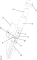
- the FIG. 1 shows a garden shovel with which it is possible, while working the moisture content and nutrient content of the soil or of plant or. To measure potting soil and to determine the ambient temperature and the lighting conditions, so that one immediately receives indicators whether the plant or seed is supplied at this point with sufficient water and nutrients and if the light and temperature conditions correspond to the plant or seed.
- the electronic garden shovel is inserted at a selected location in the ground or in the ground.
- the electronic garden shovel now measures nutrient content and soil moisture, temperature, ambient light conditions and any other parameters, and then tells the user via the display or other user interface based on the data and the current date of an internal real-time clock, not shown. whether the season and the selected location are suitable for the selected plant or vegetable species or not. If the selected location and season suitable, the planting or seed can be introduced there.
- the garden bucket has an airfoil 1, which is preferably made of glass fiber reinforced plastic is made, since this is well suited as a dielectric and has high stability and abrasion resistance.
- an airfoil 1 which is preferably made of glass fiber reinforced plastic is made, since this is well suited as a dielectric and has high stability and abrasion resistance.
- the electrodes 3, 4, 7, 8 can be vapor-deposited, glued, printed or applied by other mechanical or chemical methods. Of the four electrodes 3, 4, 7, 8 serve two first electrodes 3, 4 to the moisture of the soil to eat.
- the two other external electrodes 7, 8 are used to measure the nutrient content of the soil.
- these two outer electrodes 7, 8 are preferably made of electroless nickel / gold plating (Electroless Nickel Immersion Gold, ENIG), a method that is already used today for printed conductors on boards with a typical gold layer of 0.05 - 0.1 microns and nickel layer of 4 - 7 microns.
- ENIG Electroless Nickel Immersion Gold
- the buff gold layer prevents oxidation of the nickel. This is to prevent the further electrodes 7, 8 from decomposing and releasing toxic ions for the plants. Another possibility is that the further electrodes 7, 8 consist of a thin layer of graphite, palladium, iridium, gold, platinum, etc., ie elements or alloys thereof, which are resistant to electrochemical corrosion.
- the two inner, first electrodes 3, 4 form a plate capacitor.
- These two electrodes 3, 4 are sealed air-tight and moisture-tight over their entire surface to prevent the water or soil or air can reach directly to the electrode surfaces. They serve to determine the soil moisture. Since these electrodes 3, 4 are sealed and thus exposed to no corrosion or oxidation, their electrode material does not have to be surface-treated consuming or consist of expensive elements or alloys. For example, copper or the like can be used.
- the moist soil or the moist earth serves as a dielectric which influences the capacitance of the plate capacitor formed from the two electrodes 3, 4.
- the blade 1 and in particular the exposed outer electrodes 7, 8 are worn by the gardening, which can be done with it, the blade 1 is designed so that it can be replaced without special tools. This also opens the possibility to use blades of different shape and offer as accessories.
- an OLED or LCD display 9 and a microcontroller 5 are in the garden blade shown on or in a handle section 2, three other sensors (see Fig. 2 and 3 ) - a 3-axis acceleration sensor 17, a phototransistor 16 and a temperature sensor 15.
- the 3-axis acceleration sensor 17 measures the inclination of the electronic garden blade.
- the analog or digital and pre-filtered values of the 3 axes are fed to a microcontroller 5, which determines the position of the electronic garden bucket.
- the values displayed on the OLED or LCD display 9 are rotated so that the user can read the values no matter in which position the electronic garden shovel is currently located.
- a similar principle can already be found today in most so-called smartphones.
- the phototransistor 16 measures the illuminance, ie what proportion of the luminous flux arrives on a square meter surface of the illuminated object.
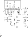
- FIGS 4-6 show a possible example of a circuit diagram for the garden shovel described above without the aforementioned internal real-time clock and user interface, which may be as mentioned, for example, buttons, trackball, miniature joystick or touchscreen.
- Fig. 4 shows as an example of the display 9, a 128 x 64 OLED display, here in the diagram referred to as U1, which is configured so that the communication runs on an I2C bus, also for the usual 5-V microcontroller 5, here in Schematic referred to as U5, the necessary level converters of the 3.3 V I2C bus and the 3.3 V reset line as well as the necessary power supplies for the complete circuit.
- Fig. 5 shows as another example a typical 5V microcontroller U5 and its peripherals.
- the microcontroller U5 has a USB interface made up of CN1 and the USB / serial converter U4 for programming and debugging. This does not necessarily have to be the case. Programming and debugging of the microcontroller U5 could also be done via an SPI interface or similar, so that CN1 and U4 could then be omitted.
- the plate capacitor comprising the first electrodes 3, 4 (in the circuit diagram: SAMPLE 1, SAMPLE 2), together with a Schmitt trigger IC2 of the type 74HC14, forms an oscillator and thus, overall, the moisture detection device.
- the frequency is between a few 100 kHz and several MHz.
- the oscillator itself is an RC oscillator, but with a first electrode not at GND, as usual, but at signal levels to minimize interference that might be spread over the ground line. The moister the soil or the earth, the greater the capacity of the capacitor and the lower the frequency of the oscillator.
- the output signal of the oscillator is fed to a digital input of the microcontroller U5, which measures the frequency of the oscillator and calculates the soil moisture from it.
- the nutrient detection device also comprises further electronic components in addition to the two further electrodes 7, 8, which can be seen in the circuit diagram as PROBE3 and PROBE4.
- One of the two further electrodes 7, 8, or in the circuit diagram PROBE3 or PROBE4 is connected to the base of a npn transistor Q5, the other via your resistor R19 with the positive supply voltage.
- the signal is fed to an analog input of the microcontroller 5, or in the circuit diagram U5. This measures the tension and calculates the nutrient content of the soil.
- PROBE 4 electrodes they are not constantly connected to the supply voltage. Via a p-channel MOSFET Q4, the sensor formed from the electrodes PROBE3 and PROBE4 is only activated by the microcontroller U5 if an instruction for measuring the nutrient content is given in the program sequence.
- Fig. 6 shows once again the five sensors of the garden shovel: consisting of three low-pass filter capacitors C17 to C19 3-axis acceleration sensor 17, here in the circuit diagram U6, consisting of the phototransistor 16, here in the circuit diagram Q3 and the resistor R13 ambient light sensor, the temperature sensor 15 consisting of IC1 and R11, the nutrient sensor consisting of the further electrodes PROBE3 and PROBE4, the npn transistor Q5, the p-channel MOSFET Q5 and the resistors R17 to R19, and the first electrodes PROBE1 and PROBE2, the Schmitt sensor. Trigger IC2 and the resistors R15 to R16 existing capacitive humidity sensor.
- the phototransistor Q3 and the resistor R13 are connected as a voltage divider.
- the signal is fed to an analog input of the microcontroller U5.
- the temperature sensor IC1 is, for example, as shown here, a digital thermometer with a programmable resolution of 9-12 bits, a measuring range of -55 ° C to + 125 ° C and a tolerance of ⁇ 0.5 ° C in the range of -10 ° C to + 85 ° C.
- the Temperature sensor IC1 measures the ambient temperature and communicates with the microcontroller U5 via the so-called single-wire bus.
- the electronic garden shovel is fed by a standard 9 V block battery 6, here in the BAT1 circuit diagram or similar compact batteries or accumulators.
- the battery BAT1 can be removed from the rear end of the handle 2 when it is unloaded.
- the cap 3 which is provided with a thread or other sealing method, must first be removed.
- the cap 3 and the handle 2 itself are waterproof, so that no water or dirt can get into the interior and damage the electronics.
- the electronics are accommodated in a chamber separate from the battery compartment in the handle section 2, which has a closure cover 13 for this purpose. From this chamber lines are led to the airfoil 1, through a hollow connecting shaft 12 of the handle portion. 2
Landscapes
- Life Sciences & Earth Sciences (AREA)
- Soil Sciences (AREA)
- Environmental Sciences (AREA)
- Engineering & Computer Science (AREA)
- Mechanical Engineering (AREA)
- Investigating Or Analyzing Materials By The Use Of Electric Means (AREA)
- Cultivation Receptacles Or Flower-Pots, Or Pots For Seedlings (AREA)
- Sowing (AREA)
Description
- Die Erfindung betrifft ein Gartengerät zur Bodenbearbeitung gemäß dem Oberbegriff des Anspruchs 1, sowie ein mit Hilfe eines solchen Gartengeräts durchgeführtes Saat- bzw. Pflanzverfahren.
- Aus der Schrift
DE 10 2009 010 579 A1 ist ein System bekannt, das eine Pflanze beim Wachsen überwacht. Um den Boden dagegen vorab daraufhin zu kontrollieren, ob er für eine bestimmte Pflanze geeignet ist, sind bereits Bodensonden bekannt, wie beispielsweise die in der deutschen PatentanmeldungDE 10 2012 106 841 A2 offenbarte Bodenfeuchtigkeitsmesssonde. Die dort erläuterte Messsonde weist einen kapazitiv arbeitenden Sensor auf, der sich in einem Gehäuse mit einer Fensterausnehmung befindet. In der Fensterausnehmung sitzt ein Zugangselement, welches mit einem hydrophilen Material imprägniert ist. Je nachdem, wie viel Wasser das umgebende Erdreich hat, zieht das Zugangselement viel oder wenig Wasser an und dient als Elektrizitätsmedium für die kapazitive Messeinrichtung. Die Bodenfeuchtigkeitsmesssonde ist jedoch zumindest für den Hobbygärtner nicht nur zu teuer, sondern auch in der Handhabung zu aufwändig. - Es gibt ferner bereits Gartensensoren, die in den Erdboden eingebracht werden und dort z.B. die Feuchte, Lichtintensität oder die Temperatur messen und beispielsweise auf Handy eines Benutzers übertragen, so dass dieser über die momentan herrschenden Bedingungen für Aussaat oder Pflanzungen, aber auch während der Wachstumsphase seiner Pflanzen informiert ist. Während mit derartigen Sensoren der gärtnerische Erfolg gesteigert werden kann, bleibt die Handhabung jedoch mühsam.
- Der Trend geht daher dahin, die Sensoren bereits in die vom Gärtner zu verwendenden Geräte zu integrieren.
- So offenbart die internationale Patentanmeldung
WO 2016 118 000 A1 ein Düngereinbringungsgerät, mit dem Löcher in den Boden gestochen und dann darin der Dünger eingebracht werden kann. Zudem weist das Gerät einen Temperatur- und einen Ph-Sensor auf, um die Temperatur oder den Ph-Wert des Bodens zu ermitteln, bevor der Dünger in den Boden eingebracht wird. Ein derartiges Düngereinbringungsgerät ist jedoch für den gärtnerischen Einsatz außerhalb der industriellen Landwirtschaft sehr teuer und vom eigentlichen Anwendungszweck her zu speziell, als dass die verwendeten Messfühler ihren vollen Nutzen ausspielen könnten. - Die kanadische Patentanmeldung
CA 2 836 642 A1 zeigt dagegen eine Gartenschaufel mit einem Feuchte- und einem Nitratgehaltssensor am Schaufelblatt. Am Schaufelstiel ist dabei ein Display vorgesehen. Ferner weist die Schaufel einen Microchip auf, der die Messergebnisse an entfernte Geräte wie Computer oder Mobiltelefone weitersenden kann. Der Nitratsensor ist dabei in eine Silikatmembran eingebettet und befindet sich hinterhalb des Schaufelblatts, wobei Diphenylamin mit Nitratpartikeln in der Silikatmembran reagiert und sich dadurch blau färbt und der Sensor eine spektrophotometrische Erfassung der Färbung und damit der Nitratmenge durchführt. Der Feuchtigkeitssensor befindet sich dagegen auf der Vorderseite des Schaufelblatts und besteht aus mikroskopischen Platten mit einer Vielzahl wasserdruckempfindlichen Scheiben, die bei Kontakt mit Wasser anschwellen und bei Erreichen einer kritischen Länge einen Aktuator kontaktieren, der ein der aufgenommenen Wassermenge entsprechendes Signal abgibt. - Hiervon ausgehend ist es Aufgabe der vorliegenden Erfindung, den Aufbau des Gartengeräts so zu verbessern, dass sich bei geringen Kosten eine hohe Robustheit und ein damit auf einfache Weise und mit hoher Zuverlässigkeit durchführbares Saat- bzw. Pflanzverfahren ergibt.
- Diese Aufgabe wird hinsichtlich des Gartengeräts mit den Merkmalen eines Anspruchs 1 gelöst, hinsichtlich des Saat- bzw. Pflanzverfahrens mit den Merkmalen des Anspruchs 10.
- Das erfindungsgemäße Gartengerät zur Bodenbearbeitung weist einen Handgriffabschnitt und einen daran angebrachten Bodenkontaktabschnitt auf. Vorzugsweise ist das Gartengerät als Gartenschaufel ausgebildet, so dass der Bodenkontaktabschnitt die Form eines Schaufelblatts hat. Weiterhin weist das erfindungsgemäße Gartengerät eine Stromversorgung, eine Feuchtigkeitserfassungseinrichtung zur Erfassung einer Anzahl einer Bodenfeuchtigkeit entsprechender Größen, eine Nährstofferfassungseinrichtung zur Erfassung einer Anzahl einem Nährstoffgehalt im Boden entsprechender Größen, eine Recheneinheit zur Berechnung der Bodenfeuchtigkeit aus der der Bodenfeuchtigkeit entsprechenden Anzahl von Größen und des Nährstoffgehalts aus der dem Nährstoffgehalt entsprechenden Größen, sowie eine Ausgabeeinrichtung zur Ausgabe der Bodenfeuchtigkeit und/oder auf der Bodenfeuchtigkeit basierenden Angaben auf sowie zur Ausgabe des Nährstoffgehalts im Boden und/oder auf dem Nährstoffgehalt basierenden Angaben. Das erfindungsgemäße Gartengerät zeichnet sich zum Einen dadurch aus, dass die Feuchtigkeitserfassungseinrichtung zwei nach Art eines Plattenkondensators voneinander so beabstandet auf dem Bodenkontaktabschnitt angebrachte, erste Elektroden aufweist, dass eine Kapazität des Plattenkondensators mit Erde als Dielektrikum beeinflusst wird, wenn die Erde mit dem Bodenkontaktabschnitt im Bereich zwischen den Elektroden kontaktiert wird. Dadurch gelingt ein kostengünstiger, aber zuverlässig arbeitender Aufbau der Feuchtigkeitserfassungseinrichtung. Zum Anderen dadurch, dass das Gartengerät eine Benutzerschnittstelle aufweist, ein Auswahlprogramm an per Benutzerschnittstelle auswählbaren Gartenpflanzen und/oder Gemüsearten, in dem günstige Sollwerte für die Bodenfeuchtigkeit oder den Nährstoffgehalt im Boden für die Gartenpflanzen und/oder Gemüsearten hinterlegt sind, sowie eine Vergleichereinrichtung, welche die hinterlegten Sollwerte für die ausgewählte Gartenpflanze oder Gemüseart mit den erfassten Istwerten für Bodenfeuchtigkeit und/oder Nährstoffgehalt im Boden vergleicht und das Ergebnis zur Ausgabe auf der Ausgabeeinrichtung übermittelt. Es lässt sich also direkt anzeigen, ob sich die ermittelte Bodenfeuchtigkeit und der ermittelte Nährstoffgehalt für eine bestimmte Pflanze eignet.
- Das erfindungsgemäße Saat- bzw. Pflanzverfahren umfasst die folgenden Schritte:
Ermittlung eines für eine bestimmte, auszusäende oder zu pflanzende Gartenpflanze oder Gemüseart günstigen Sollwerts für die Bodenfeuchtigkeit und den Nährstoffgehalt im Boden, an einer zur Aussaat bzw. zum Pflanzen angedachten Stelle das Ermitteln eines Istwerts der Bodenfeuchtigkeit und des Nährstoffgehalts im Boden, anschließend Vergleich des jeweiligen Sollwerts mit dem jeweiligen Istwert und, falls der Vergleich positiv ausfällt, Aussaat bzw. Pflanzen der Gartenpflanze oder Gemüseart, wobei das Ermitteln der Ist- und Sollwerte für die Bodenfeuchtigkeit und des Nährstoffgehalts im Boden mit Hilfe des erfindungsgemäßen Gartengeräts durchgeführt wird, welches dazu an der zur Aussaat bzw. zum Pflanzen vorgesehenen Stelle in den Boden gesteckt wird und welches dann im positiven Vergleichsfall gleich zum Erstellen des Lochs für den Samen oder die Pflanze bei der Aussaat bzw. beim Pflanzen dienen kann. - Vorteilhaft ist die Recheneinheit dabei dazu eingerichtet, aus der Kapazität des Plattenkondensators und/oder aus einer aus der Kapazität des Plattenkondensators abgeleiteten Größe als Eingangsgröße eine die Bodenfeuchtigkeit wiedergebende Ausgangsgröße zu errechnen. Dazu kann die Recheneinheit eine in ihrem Speicher abgelegte Lookup-Tabelle oder dergleichen enthalten, aus der der Zusammenhang hervorgeht.
- Je nach Stärke des Dielektrikums zwischen den Elektroden der Feuchtigkeitserfassungseinrichtung, also je nach Bodenfeuchtigkeit ergibt sich dabei ein anderer Wert für die Kapazität des durch die beiden Elektroden gebildeten Plattenkondensators. Die Kapazität kann dabei erfasst werden. Deutlich einfacher und genauer lässt sich jedoch eine Schwingungsfrequenz als Maß für die Kapazität des Plattenkondensators bzw. die Dielektrizität der Erde und damit die Bodenfeuchte ermitteln. Vorteilhaft weist die Feuchtigkeitserfassungseinrichtung daher einen mit dem Plattenkondensator zu einer Oszillatorschaltung zusammengeschalteten Schwingungserzeuger auf. Einfach auswerten lässt sich die Oszillatorschaltung, wenn diese als Kippschwinger binäre Ausgangssignale abgibt. Dazu kann der Schwingungserzeuger als Schmitt-Trigger ausgebildet sein. Die Frequenz der durch Kontakt mit der Erde erzeugten Schwingung kann dann anstatt oder zusätzlich zur Kapazität des Plattenkondensators der Recheneinheit als Eingangsgröße für die Bodenfeuchtigkeit zugeführt werden.
- Um die beiden Elektroden nicht kurzzuschließen ist es vorteilhaft, wenn der Bodenkontaktabschnitt, auf dem die Elektroden aufgebracht sind, also beispielsweise das Schaufelblatt aus einem nicht leitenden und vorzugsweise gut dielektrisch wirkenden Material besteht. Es wäre aber auch denkbar, an einem Gartengerät, wie beispielsweise einer Harke die beiden Elektroden auf unterschiedlichen Zinken der Harke anzubringen, die zusammen den Bodenkontaktabschnitt bilden, aber nicht elektrisch leitend miteinander verbunden sind, daher auch aus Metall bestehen können. Vorteilhaft besteht der Bodenkontaktabschnitt jedoch aus Kunststoff, wobei auf dessen Oberfläche die Elektroden aufgebracht sein können, so dass sie mit dem Boden bzw. der Erde in Kontakt bringbar sind. Es wäre auch denkbar, nur Teile des Schaufelblatts bzw. des Bodenkontaktabschnitts aus Kunststoff auszubilden. Weiter bevorzugt ist jedoch, wenn der Bodenkontaktabschnitt vollständig aus faserverstärktem Kunststoff gefertigt ist, wobei sich insbesondere glasfaserverstärkter Kunststoff gut eignet, da dieser neben einer hohen Festigkeit und Abriebarmut auch noch stark dielektrisch wirkt.
- Die Elektroden der Feuchtigkeitserfassungseinrichtung können dann vorteilhaft aus einem leitfähigen Material wie Kupfer oder einer Kupferlegierung bestehen und gegenüber der Umgebung luft- und feuchtigkeitsdicht versiegelt auf dem Bodenkontaktabschnitt aufgebracht sein. Darum sind die Elektroden nicht nur kostengünstig herstellbar, sondern auch gegen Korrosion oder Oxidation geschützt, so dass das Elektrodenmaterial nicht aufwendig oberflächenbehandelt oder aus teuren Elementen oder Legierungen bestehen muss. Durch die Versiegelung wird zudem verhindert, dass die Elektroden in direktem Kontakt mit dem Erdboden treten, so dass ein unerwünschter Stromfluss vermieden wird. Möglich wäre es ferner, die beiden Elektroden versetzt zueinander auf Vorder- und Rückseite des Schaufelblatts bzw. des Bodenkontaktabschnitts aufzubringen. Es wäre jedoch auch denkbar, die Elektroden in das Innere des Kunststoffs einzubetten oder sogar in das Gewebe der Faserverstärkung einzuflechten.
- Vorteilhaft ist der Bodenkontaktabschnitt dabei ferner auswechselbar und insbesondere ohne Werkzeug auswechselbar an dem Handgriffabschnitt angebracht, beispielsweise über einen Bajonettverschluss oder die aus dem Gartenbereich hinlänglich bekannten Steckverbindungen, z.B. von der Fa. Gardena. Für die elektrische Kontaktierung der Elektroden könnte dabei eine zusätzliche Steckverbindung oder dergleichen vorgesehen sein. Das Schaufelblatt oder der als ein anderes Arbeitsgerät gestalteter Bodenkontaktabschnitt kann dann einfach ausgetauscht werden, wenn es abgenutzt ist, ohne dass der die Elektronik enthaltende Handgriffabschnitt erneuert werden muss.
- Entsprechend umfasst der Handgriffabschnitt vorteilhaft einen Stiel, in dem ein Microcontroller der Recheneinheit und eine Anzahl Batterien der Stromversorgung untergebracht sind, z. B. ein 9-V- Block oder ein aufladbarer Akku, wobei an dem Stiel ein Ein/Aus-Schalter und vorzugsweise auch ein Display der Ausgabeeinrichtung angeordnet ist.
- Vorzugsweise weist der Handgriffabschnitt dabei an seinem dem Bodenkontaktabschnitt abgewandten Ende eine abnehmbare Verschlusskappe auf, über die ein Batterieaufnahmefach im Inneren des Stiels zugänglich ist, so dass die Batterie entnommen bzw. getauscht werden kann, wenn sie entladen ist. Die Verbindung der Verschlusskappe mit dem Handgriffabschnitt ist dabei vorteilhaft wasserdicht ausgeführt, so dass kein Schmutz oder Wasser in das Innere des Batteriefachs gelangen kann. Das gilt natürlich für die weitere, im Inneren des Stiels bevorzugt in einer separaten Kammer aufgenommene Elektronik, wie beispielsweise den Microcontroller der Recheneinheit, wobei diese Kammer auch fest verschlossen sein kann.
- Gemäß einer weiteren bevorzugten Ausbildung könnte ein aufladbarer Akkumulator als Batterie vorgesehen sein, wobei das Gartengerät an seinem Handgriffabschnitt und dort bevorzugt an seinem den Bodenkontaktabschnitt abgewandten Ende eine entsprechende Anschlussbuchse für ein Ladegerät aufweist. Weiterhin denkbar wäre auch ein kontaktloses Akku-Ladesystem, insbesondere ein induktives Ladesystem nach Art einer elektrischen Zahnbürste, so dass dann die Batterie fest verbaut und im Inneren des Stiels eingesiegelt sein könnte.
- In besonders bevorzugter Weiterbildung der Ausführung des Gartengeräts mit einem auswechselbar an dem Handgriffabschnitt angebrachten Bodenkontaktabschnitt weist das Gartengerät eine Mehrzahl unterschiedlich geformter, jeweils mit den beiden ersten Elektroden versehener und auf den Handgriffabschnitt passender Bodenkontaktabschnitte auf. Das Gartengerät kann dann zu vielseitigen Einsatzzwecken verwendet werden. Beispielsweise könnte einer der Bodenkontaktabschnitte als ein Schaufelblatt, ein weiterer Bodenkontaktabschnitt als eine Kelle und wieder ein anderer Bodenkontaktabschnitt als eine Hacke ausgebildet sein etc..
- Weiterhin vorteilhaft kann die Nährstofferfassungseinrichtung dabei so aufgebaut sein, dass sie eine elektrische Leitfähigkeit des Bodens als Maß für den Nährstoffgehalt erfasst. Dazu kann sie zwei voneinander beabstandet auf dem Bodenkontaktabschnitt des Gartengeräts bzw. falls vorhanden auf jedem der unterschiedlichen Bodenkontaktabschnitte angebrachte, weitere Elektroden umfassen. Über die beiden weiteren Elektroden kann die elektrische Leitfähigkeit des Bodens gemessen werden, welche umso größer ist, je mehr Nährstoffionen sich im Boden befinden und daher ein Maß für den Nährstoffgehalt des Bodens bildet.
- Die beiden ersten Elektroden befinden sich dabei vorteilhaft örtlich zwischen den beiden weiteren Elektroden der Nährstofferfassungseinrichtung, so dass sie so nahe beieinander angeordnet sein können, dass sie einen Plattenkondensator ausbilden können, wohingegen die Entfernung der beiden weiteren Elektroden der Nährstofferfassungseinrichtung, die ja einen Stromfluss zwischen sich erlauben sollen, weiter voneinander beabstandet sein können.
- Insbesondere bei einem aus Kunststoff wie z.B. ABS oder CFK bestehenden Bodenkontaktabschnitt lässt sich eine aus Chemisch Nickel bestehende Schicht sehr gut abscheiden. Vorteilhaft können die beiden weiteren Elektroden daher aus Chemisch Nickel bestehen oder eine Schicht aus Chemisch Nickel umfassen. Weiterhin vorteilhaft ist die Nickelschicht dabei mit einer Goldschicht bedeckt, welche nicht nur die Oxidation des Nickels verhindert, sondern auch einen gut leitfähigen Kontakt zum Erdreich herstellen kann. Die beiden weiteren Elektroden bestehen also besonders bevorzugt aus Chemisch Nickel/Sudgold. Die Nickelschicht kann dabei beispielsweise zwischen 4 und 7 µm dick sein, die darauf angebrachte Goldschicht zwischen 0,05 und 0,1 µm.
- Mittels der Goldschicht soll auch verhindert werden, dass sich die Elektroden, also der Nickel, zersetzt und dabei für die Pflanzen giftige Ionen freigesetzt werden. Es wäre aber auch denkbar, dass die Elektroden aus einer dünnen Schicht Grafit, Palladium, Ridium, Gold, Platin oder ähnlichen Elementen oder Legierungen daraus bestehen, die gegen elektrochemische Korrosion und Oxidation beständig (er) sind.
- Weiterhin vorteilhaft kann die Ausgabevorrichtung ein Kommunikationsmodul umfassen, mit dem drahtlos Daten auf ein externes Gerät, wie z.B. ein Smartphone oder einen PC übertragen werden können. Das Kommunikationsmodul kann dabei beispielsweise als Bluetooth-Funkmodul oder als WLAN-Funkmodul ausgebildet sein und alternativ oder ergänzend zu dem Display am Stiel des Handgriffsabschnitts vorgesehen sein. Damit gelingt nicht nur ein besserer Überblick über die ermittelten Messwerte und die für die Aussaat oder Pflanzung daraus folgenden Konsequenzen, also ob die Stelle, an der das Gartengerät in den Boden gesteckt worden ist, sich für die Aussaat bzw. Pflanzung eignet oder nicht. Vielmehr können die Daten auf den externen Geräten auch weiterverarbeitet werden, oder es kann dort auf einfache Weise eine Benutzerschnittstelle beispielsweise in Form einer Softwareapplikation bereit gestellt werden, an der dem Benutzer eine Auswahl an Gartenpflanzen und/oder Gemüsearten bereit gestellt werden kann. Dieses Auswahlprogramm kann dann weiterhin beispielsweise in Form einer Datenbank oder Lookup-Tabelle günstige Sollwerte für die Bodenfeuchtigkeit oder den Nährstoffgehalt im Boden aufweisen, sowie eine ebenfalls vorzugsweise als Software ausgebildete Vergleichereinrichtung, welche die hinterlegten Sollwerte für die ausgewählte Gartenpflanze oder Gemüseart mit den erfassten Istwerten für die Bodenfeuchtigkeit und/oder den Nährstoffgehalt im Boden vergleicht und das Ergebnis dann zur Ausgabe auf der Ausgabeeinrichtung bzw. auf dem externen Gerät übermittelt.
- Das Gartengerät weist eine solche Benutzerschnittstelle beispielsweise in Form eines Touchscreens oder in Form von Auswahltasten oder dergleichen jedoch bereits lokal am Gerät selbst auf, ebenso das vorstehend genannte Auswahlprogramm und die Vergleichseinrichtung, etwa in Form von auf dem Microcontroller der Recheneinheit ablaufenden Programmroutinen. Hierzu könnte das Gartengerät einen Speicher wie z.B. eine Micro-SD-Karte enthalten. Es wäre aber wie gesagt ebenso denkbar, die Benutzerschnittstelle und die zugehörige Software alternativ oder ergänzend ganz oder in Teilen als Teil des Gartengeräts auf ein externes Gerät auszulagern.
- Weiterhin kann das Gartengerät ergänzend zur Erfassung von weiteren das Aussaat- bzw. Pflanzergebnis beeinflussenden Parametern eingerichtet sein.
- Insbesondere könnte das Gartengerät eine Temperaturerfassungseinrichtung zur Erfassung einer Anzahl der Umgebungstemperatur entsprechender Größen aufweisen, also beispielsweise einen Temperatursensor in Form eines digitalen Thermometers, welcher z.B. über eine Busverbindung an den Microcontroller angeschlossen ist. Denkbar wären auch weitere Sensoren, die beispielsweise die Farbtemperatur des Umgebungslichtes, den pH-Wert des Bodens oder den Luftstrom messen.
- Weiterhin kann das Gartengerät eine Lichterfassungseinrichtung zur Erfassung einer Anzahl den Lichtverhältnissen in der Umgebung entsprechender Größen aufweisen, beispielsweise in Form eines Fototransistors, welcher eine Beleuchtungsstärke des auftreffenden Lichts misst und welcher ebenfalls an dem Microcontroller angeschlossen sein kann. Der Microcontroller kann dann aus dem Lichtstrom die Beleuchtungsstärke messen. Ebenfalls denkbar wäre es, die Lichterfassungseinrichtung als Solarzelle auszubilden.
- Weiterhin kann das Gartengerät eine Uhreinrichtung zur Bestimmung der Jahreszeit aufweisen. Denn das Saat- bzw. Pflanzergebnis hängt maßgeblich davon ab, dass zur richtigen Jahreszeit gesät bzw. gepflanzt wird.
- Wenn das Gartengerät durch diese vorstehend angesprochenen zusätzlichen Einrichtungen ergänzt ist, kann natürlich auch das erfindungsgemäße Saat- bzw. Pflanzverfahren weiter verfeinert werden, wobei nicht nur günstige Sollwerte für die Bodenfeuchtigkeit und den Nährstoffgehalt im Boden bestimmt werden, sondern auch für die Umgebungstemperatur, die Lichtverhältnisse in der Umgebung und/oder die Aussaat bzw. Pflanzjahreszeit, welche dann mit den ermittelten Istwerten verglichen werden können, um noch genauer festlegen zu können, ob die Aussaat bzw. das Pflanzen durchgeführt werden soll.
- Im Folgenden wird anhand der beiliegenden Zeichnungen eine vorteilhafte Ausführungsform der Erfindung näher erläutert.
- Es zeigen:
- Figur 1
- eine perspektivische Ansicht einer Gartenschaufel gemäß einer vorteilhaften Ausführungsform der Erfindung;
- Figur 2
- eine Explosionsdarstellung der in der
Fig. 1 gezeigten Gartenschaufel; - Figur 3
- eine weitere Explosionsdarstellung der in der
Fig. 1 gezeigten Gartenschaufel; und die -
Figuren 4-6 Schaltpläne der in denFiguren 1-3 gezeigten Gartenschaufel. - Die
Figur 1 zeigt eine Gartenschaufel mit der es möglich ist, während dem Arbeiten die Feuchte und den Nährstoffgehalt des Bodens oder von Pflanzen-bzw. Blumenerde zu messen sowie die Umgebungstemperatur und die Lichtverhältnisse zu bestimmen, so dass man unmittelbar Indikatoren erhält, ob das Pflanz- oder Saatgut an dieser Stelle mit ausreichend Wasser und Nährstoffen versorgt ist und ob die Licht- und Temperaturverhältnisse dem Pflanz- oder Saatgut entsprechen. - Hierzu wird die elektronische Gartenschaufel an einer ausgewählten Stelle in den Boden bzw. in die Erde gesteckt. Die elektronische Gartenschaufel misst nun Nährstoffgehalt und Feuchte des Bodens bzw. der Erde, Temperatur, Lichtverhältnisse der Umgebung und etwaige andere Parameter und teilt dann anhand der Daten und des aktuellen Datums einer nicht gezeigten internen Echtzeituhr dem Benutzer über das Display oder einem anderen Benutzerinterface mit, ob die Jahreszeit und die ausgewählte Stelle für die gewählte Pflanze oder Gemüseart geeignet ist oder nicht. Ist die ausgewählte Stelle und Jahreszeit geeignet, kann das Pflanz- oder Saatgut dort eingebracht werden.
- Die Gartenschaufel weist ein Schaufelblatt 1 auf, welches vorzugsweise aus glasfaserverstärkten Kunststoff gefertigt ist, da dieser sich gut als Dielektrikum eignet und hohe Stabilität und Abriebfestigkeit aufweist. Auf der Oberseite des Schaufelblattes 1 sind vier Elektroden 3, 4, 7, 8 aufgebracht. Es wäre aber ebenso denkbar, die Elektroden auf der Unterseite des Schaufelblatts anzubringen. Die Elektroden 3, 4, 7, 8 können aufgedampft, aufgeklebt, aufgedruckt oder durch sonstige mechanische oder chemische Verfahren aufgebracht sein.Von den vier Elektroden 3, 4, 7, 8 dienen zwei erste Elektroden 3, 4 dazu, um die Feuchte des Bodens zu messen. Die beiden weiteren, äußeren Elektroden 7, 8 dienen zur Messung des Nährstoffgehalts des Bodens.
- Je mehr Nährstoffionen sich im Boden befinden, desto größer ist die elektrische Leitfähigkeit. Um elektrochemische Korrosion der weiteren Elektroden 7, 8 zu vermeiden, sind diese beiden außenliegenden Elektroden 7, 8 vorzugsweise aus Chemisch Nickel/Sudgold (Electroless Nickel Immersion Gold, ENIG) gefertigt, ein Verfahren, das heute bereits bei Leiterbahnen auf Platinen angewandt wird mit einer typischen Gold-Schicht von 0,05 - 0,1 µm und Nickel-Schicht von 4 - 7 µm.
- Die Sudgold-Schicht verhindert die Oxidation des Nickels. So soll verhindert werden, dass sich die weiteren Elektroden 7, 8 zersetzen und für die Pflanzen giftige Ionen freisetzen. Eine weitere Möglichkeit besteht darin, dass die weiteren Elektroden 7, 8 aus einer dünnen Schicht Graphit, Palladium Iridium, Gold, Platin etc. bestehen, also Elemente oder Legierungen daraus, die gegen elektrochemische Korrosion beständig sind.
- Die beiden inneren, ersten Elektroden 3, 4 bilden einen Plattenkondensator. Diese beiden Elektroden 3, 4 sind über deren komplette Oberfläche luft- und feuchtigkeitsdicht versiegelt, um zu verhindern, das Wasser oder Erde oder Luft direkt an die Elektrodenflächen gelangen kann. Sie dienen zur Ermittlung der Bodenfeuchte. Da diese Elektroden 3, 4 versiegelt und dadurch keiner Korrosion oder Oxidation ausgesetzt sind, muss ihr Elektrodenmaterial nicht aufwendig oberflächenbehandelt werden oder aus teuren Elementen oder Legierungen bestehen. Es kann beispielsweise Kupfer oder ähnliches verwendet werden. Der feuchte Boden bzw. die feuchte Erde dient hier als Dielektrikum, das die Kapazität des aus den beiden Elektroden 3, 4 gebildeten Plattenkondensators beeinflusst.
- Da das Schaufelblatt 1 und vor allem die freiliegenden äußeren Elektroden 7, 8 durch die Gartenarbeit, die damit verrichtet werden kann, abgenutzt werden, ist das Schaufelblatt 1 so gestaltet, dass sich dieses ohne Spezialwerkzeug austauschen lässt. Dadurch eröffnet sich zudem die Möglichkeit, Schaufelblätter unterschiedlicher Form einzusetzen und als Zubehör anzubieten.
- Neben einem EIN/AUS-Schalter 10, einem OLED- oder LCD-Display 9 und einem Microcontroller 5 befinden sich bei der gezeigten Gartenschaufel an oder in einem Handgriffabschnitt 2 drei weitere Sensoren (siehe
Fig. 2 und3 ) - ein 3-Achsen-Beschleunigungssensor 17, ein Fototransistor 16 und ein Temperatursensor 15. Der 3-Achsen-Beschleunigungssensor 17 misst die Neigung der elektronischen Gartenschaufel. Die analogen oder digitalen und vorab gefilterten Werte der 3 Achsen werden einem Microcontroller 5 zugeführt, der die Position der elektronischen Gartenschaufel ermittelt. - Je nach Neigung werden die auf dem OLED- oder LCD-Display 9 angezeigten Werte gedreht, so dass der Benutzer die Werte, egal in welcher Position sich die elektronische Gartenschaufel gerade befindet, ablesen kann. Ein ähnliches Prinzip findet man heute bereits bei den meisten sogenannten Smartphones. Zudem wäre es möglich, den 3-Achsen-Beschleunigungssensor 17 als Benutzerschnittstelle zu nutzen.
- Der Fototransistor 16 misst die Beleuchtungsstärke, also welcher Anteil vom Lichtstrom auf einem Quadratmeter Fläche des beleuchteten Objekts ankommt.
- Die
Figuren 4-6 zeigen ein mögliches Beispiel eins Schaltplanes für die vorstehend beschriebene Gartenschaufel ohne die erwähnte interne Echtzeituhr und Benutzerschnittstelle, die wie erwähnt beispielsweise aus Tasten,Trackball, Miniatur-Joystick oder Touchscreen bestehen kann. -
Fig. 4 zeigt als Beispiel für das Display 9 ein 128 x 64 OLED-Display, hier im Schaltplan bezeichnet als U1, das so konfiguriert ist, dass die Kommunikation über einen I2C-Bus läuft, zudem für den üblichen 5-V-Microcontroller 5, hier im Schaltplan bezeichnet als U5, die notwendigen Pegelwandler des 3,3 V I2C-Busses und der 3,3 V Reset-Leitung sowie die notwendigen Spannungsversorgungen für die komplette Schaltung. -
Fig. 5 zeigt als weiteres Beispiel einen typischen 5-V-Microcontroller U5 und dessen Peripherie. In der Abbildung verfügt der Microcontroller U5 über eine USB-Schnittstelle gebildet aus CN1 und dem USB/Seriell-Umsetzer U4, um diesen zu programmieren und um zu debuggen. Dies muss aber nicht notwendigerweise der Fall sein. Programmierung und Debugging des Microcontrollers U5 könnte auch über eine SPI-Schnittstelle oder ähnliches erfolgen, so dass CN1 und U4 dann entfallen könnten. - Der die ersten Elektroden 3, 4 (im Schaltplan: PROBE 1, PROBE 2) aufweisende Plattenkondensator bildet zusammen mit einem Schmitt-Trigger IC2 vom Typ 74HC14 einen Oszillator und somit insgesamt die Feuchtigkeitserfassungseinrichtung. Je nach Fläche des Kondensators liegt die Frequenz zwischen einigen 100 kHz und mehreren MHz. Der Oszillator selbst ist ein RC-Oszillator, wobei jedoch die eine erste Elektrode nicht wie üblich auf GND sondern auf Signalpegel liegt, um Störungen welche über die Masseleitung einstreuen könnten, zu minimieren. Je feuchter nun der Boden oder die Erde, desto größer die Kapazität des Kondensators und desto niedriger die Frequenz des Oszillators. Das Ausgangssignal des Oszillators wird einem Digital-Eingang des Microcontrollers U5 zugeführt, der die Frequenz des Oszillators misst und daraus die Bodenfeuchte errechnet.
- Die Nährstofferfassungseinrichtung umfasst neben den beiden weiteren Elektroden 7, 8, die im Schaltplan als PROBE3 und PROBE4 zu entnehmen sind, ebenfalls weitere elektronische Bauteile. Eine der beiden weiteren Elektroden 7, 8, bzw. im Schaltplan PROBE3 oder PROBE4 ist mit der Basis eines npn-Transistors Q5 verbunden, die andere über deinen Vorwiderstand R19 mit der positiven Versorgungsspannung. Je leitfähiger der Boden, desto mehr leitet der Transistor Q5. Der Transistor Q5 , der hier selbst wie ein Widerstand fungiert, bildet mit dem Widerstand an einem Emitter R17 einen Spannungsteiler. Das Signal wird einem Analog-Eingang des Microcontrollers 5, bzw. im Schaltplan U5 zugeführt. Dieser misst die Spannung und errechnet daraus den Nährstoffgehalt des Bodens. Um die Lebensdauer der Elektroden PROBE 3, PROBE 4, zusätzlich zu erhöhen, sind sie nicht ständig mit der Versorgungsspannung verbunden. Über einen p-Kanal MOSFET Q4 wird der aus den Elektroden PROBE3 und PROBE4 gebildete Sensor nur dann vom Microcontroller U5 aktiviert, wenn im Programmablauf ein Befehl zu Messung des Nährstoffgehalts gegeben wird.
-
Fig. 6 zeigt noch einmal die fünf Sensoren der Gartenschaufel: Den aus drei Tiefpassfilter-Kondensatoren C17 bis C19 bestehenden 3-Achsen-Beschleunigungssensor 17, hier im Schaltplan U6, den aus dem Fototransistor 16, hier im Schaltplan Q3 und dem Widerstand R13 bestehenden Umgebungslichtsensor, den Temperatursensor 15 bestehend aus IC1 und R11, den aus den weiteren Elektroden PROBE3 und PROBE4, dem npn-Transistor Q5, dem p-Kanal MOSFET Q5 und den Widerständen R17 bis R19 bestehenden Nährstoffsensor, sowie den aus den ersten Elektroden PROBE1 und PROBE2, dem Schmitt-Trigger IC2 und den Widerständen R15 bis R16 bestehenden kapazitiven Feuchtigkeitssensor. - Der Fototransistor Q3 und der Widerstand R13 sind als Spannungsteiler beschaltet. Das Signal wird einem analogen Eingang des Microcontroller U5 zugeführt. Je größer der Anteil des Lichtstroms, desto größer die Spannung am Ausgang des Spannungsteilers. Aus der gemessenen Spannung errechnet der Microcontroller U5 dann die Beleuchtungsstärke. Der Temperatursensor IC1 ist beispielsweise wie hier dargestellt ein digitales Thermometer mit einer programmierbaren Auflösung von 9-12 Bit, einem Messbereich von -55°C bis +125°C und einer Toleranz von ±0.5°C im Bereich von -10°C bis +85°C. Der Temperatursensor IC1 misst die Umgebungstemperatur und kommuniziert mit dem Microcontroller U5 über den sogenannten Eindraht-Bus.
- Gespeist wird die elektronische Gartenschaufel durch eine handelsübliche 9-V-Blockbatterie 6, hier im Schaltplan BAT1 oder ähnliche kompakte Batterien oder Akkumulatoren. Die Batterie BAT1 kann vom hinteren Ende des Handgriffs 2 entnommen bzw. getauscht werden, wenn sie entladen ist. Dazu muss vorher die Verschlusskappe 3, die mit einem Gewinde oder sonstigem Verschlussverfahren versehen ist, entfernt werden. Die Verschlusskappe 3 sowie der Handgriff 2 selbst sind wasserdicht ausgeführt, so dass kein Wasser oder Schmutz in das Innere gelangen und die Elektronik beschädigen kann.
- Auch denkbar wäre, die Batterie zum Laden nicht entnehmen zu müssen. Die elektronische Gartenschaufel müsste dann über eine entsprechende Anschlussbuchse für ein Ladegerät verfügen oder über ein kontaktloses Akku-Ladesystem, wie es heute beispielsweise bereits für elektrische Zahnbürsten üblich ist.
- Die Elektronik ist dabei in einer vom Batteriefach separaten Kammer im Handgriffabschnitt 2 untergebracht, welcher dafür einen Verschlussdeckel 13 aufweist. Aus dieser Kammer sind Leitungen zum Schaufelblatt 1 geführt, und zwar durch einen hohlen Verbindungsschaft 12 des Handgriffabschnitts 2.
- Abwandlungen und Modifikationen der gezeigten Ausführungsform sind möglich, ohne den Rahmen der Erfindung zu verlassen.
Claims (10)
- Gartengerät zur Bodenbearbeitung, mit einem Handgriffabschnitt, einem daran angebrachten Bodenkontaktabschnitt, beispielsweise einem Schaufelblatt (1), einer Stromversorgung, einer Feuchtigkeitserfassungseinrichtung zur Erfassung einer Anzahl einer Bodenfeuchtigkeit entsprechender Größen, eine Nährstofferfassungseinrichtung zur Erfassung einer Anzahl einem Nährstoffgehalt im Boden entsprechender Größen, einer Recheneinheit zur Berechnung der Bodenfeuchtigkeit aus der der Bodenfeuchtigkeit entsprechenden Anzahl von Größen und des Nährstoffgehalts aus der dem Nährstoffgehalt entsprechenden Größen, sowie einer Ausgabeeinrichtung zur Ausgabe der Bodenfeuchtigkeit und/oder auf der Bodenfeuchtigkeit basierenden Angaben, sowie des Nährstoffgehalts im Boden und/oder auf dem Nährstoffgehalt basierenden Angaben, dadurch gekennzeichnet, dass die Feuchtigkeitserfassungseinrichtung zumindest zwei nach Art eines Plattenkondensators voneinander beabstandet auf dem Bodenkontaktabschnitt angebrachte, erste Elektroden (3, 4) aufweist, wobei eine Kapazität des Plattenkondensators mit Erde als Dielektrikum beeinflusst wird, wenn die Erde mit dem Bodenkontaktabschnitt im Bereich zwischen den Elektroden (3, 4) kontaktiert wird, wobei
das Gartengerät eine Benutzerschnittstelle aufweist, ein Auswahlprogramm an per Benutzerschnittstelle auswählbaren Gartenpflanzen und/oder Gemüsearten, in dem günstige Sollwerte für die Bodenfeuchtigkeit oder den Nährstoffgehalt im Boden für die Gartenpflanzen und/oder Gemüsearten hinterlegt sind, sowie eine Vergleichereinrichtung, welche die hinterlegten Sollwerte für die ausgewählte Gartenpflanze oder Gemüseart mit den erfassten Istwerten für Bodenfeuchtigkeit und/oder Nährstoffgehalt im Boden vergleicht und das Ergebnis zur Ausgabe auf der Ausgabeeinrichtung übermittelt. - Gartengerät nach Anspruch 1, dadurch gekennzeichnet, dass die Recheneinheit dazu eingerichtet ist, aus der Kapazität des Plattenkondensators und/oder aus einer aus der Kapazität des Plattenkondensators abgeleiteten Größe als Eingangsgröße eine die Bodenfeuchtigkeit wiedergebende Ausgangsgröße zu errechnen.
- Gartengerät nach Anspruch 1 oder 2, dadurch gekennzeichnet, dass die Feuchtigkeitserfassungseinrichtung einen mit dem Plattenkondensator zu einer Oszillatorschaltung, insbesondere zu einem Kippschwinger zusammengeschalteten Schwingungserzeuger aufweist, insbesondere einen Schmitt-Trigger, wobei die Frequenz der erzeugten Schwingung und/oder die Kapazität des Plattenkondensators der Recheneinrichtung (6) als Eingangsgröße für die Bodenfeuchtigkeit zugeführt wird.
- Gartengerät nach einem der vorhergehenden Ansprüche, dadurch gekennzeichnet, dass die beiden ersten Elektroden (3, 4) der Feuchtigkeitserfassungseinrichtung aus einem leitfähigen Material wie Kupfer oder einer Kupferlegierung bestehen und gegenüber der Umgebung luft- und feuchtigkeitsdicht versiegelt auf den Bodenkontaktabschnitt aufgebracht sind.
- Gartengerät nach einem der vorhergehenden Ansprüche, dadurch gekennzeichnet, dass der Bodenkontaktabschnitt auswechselbar, insbesondere werkzeuglos auswechselbar, beispielsweise über einen Bajonettverschluss an dem Handgriffabschnitt angebracht ist, wobei der Handgriffabschnitt einen Stiel (2) umfasst, in dem ein Microcontroller (5) der Recheneinheit und eine Anzahl vorzugsweise aufladbarer Batterien (6) der Stromversorgung untergebracht sind, wobei an dem Stiel ein EIN-/AUSSchalter (10) und vorzugsweise auch ein Display (9) der Ausgabeeinrichtung angeordnet ist, und wobei die Vergleichereinrichtung insbesondere eine auf dem Microcontroller (5) laufende Programmroutine ist.
- Gartengerät nach einem der vorhergehenden Ansprüche, dadurch gekennzeichnet, dass das Gartengerät eine Temperaturerfassungseinrichtung (15) zur Erfassung einer Anzahl der Umgebungstemperatur entsprechender Größen, eine Lichterfassungseinrichtung (16) zur Erfassung einer Anzahl den Lichtverhältnissen in der Umgebung entsprechender Größen und/oder eine Uhreinrichtung zur Bestimmung der Jahreszeit aufweist, wobei die Recheneinheit zur Berechnung des Nährstoffgehalts im Boden, der Umgebungstemperatur, der Lichtverhältnisse in der Umgebung und/oder der Jahreszeit eingerichtet ist, und wobei die Ausgabeeinrichtung zur Ausgabe des Nährstoffgehalts im Boden, der Umgebungstemperatur, der Lichtverhältnisse in der Umgebung und/oder der Jahreszeit eingerichtet ist, wobei die Nährstofferfassungseinrichtung eine elektrische Leitfähigkeit des Bodens als Maß für den Nährstoffgehalt erfasst und dazu zumindest zwei voneinander beabstandet auf dem, bzw. jedem Bodenkontaktabschnitt angebrachte, weitere Elektroden (7, 8) umfasst.
- Gartengerät nach Anspruch 6, dadurch gekennzeichnet, dass die beiden weiteren Elektroden (7, 8) eine als Chemisch Nickel auf den Bodenkontaktabschnitt abgeschiedenen Schicht umfassen oder daraus bestehen, welche vorzugsweise mit einer Goldschicht bedeckt ist.
- Gartengerät nach einem der vorhergehenden Ansprüche, dadurch gekennzeichnet, dass der Bodenkontaktabschnitt aus Kunststoff, vorzugsweise faserverstärktem Kunststoff wie beispielsweise glasfaserverstärktem Kunststoff gefertigt ist, auf dessen Oberfläche die Elektroden (3, 4, 7, 8) aufgebracht sind.
- Gartengerät nach einem der vorhergehenden Ansprüche, dadurch gekennzeichnet, dass in dem Auswahlprogramm ferner günstige Sollwerte für Umgebungstemperatur, Lichtverhältnisse in der Umgebung und/oder Aussaat- bzw Pflanzjahreszeit für die Gartenpflanzen und/oder Gemüsearten hinterlegt sind, und die Vergleichereinrichtung auch diese hinterlegten Sollwerte für die ausgewählte Gartenpflanze oder Gemüseart mit den erfassten Istwerten für die Umgebungstemperatur, Lichtverhältnisse in der Umgebung und/oder Jahreszeit vergleicht und das Ergebnis zur Ausgabe auf der Ausgabeeinrichtung übermittelt.
- Saat- bzw. Pflanzverfahren, wobei für eine auszusäende oder zu pflanzende Gartenpflanze und/oder Gemüseart günstige Sollwerte für Bodenfeuchtigkeit, Nährstoffgehalts im Boden, Umgebungstemperatur, Lichtverhältnisse in der Umgebung und/oder Aussaat- bzw Pflanzjahreszeit ermittelt werden, an einer zur Aussaat bzw. zum Pflanzen angedachten Stelle Istwerte für Bodenfeuchtigkeit, Nährstoffgehalt im Boden, Umgebungstemperatur, Lichtverhältnisse in der Umgebung und/oder Jahreszeit ermittelt werden, dann die Sollwerte mit den Istwerten verglichen werden, und, falls der Vergleich positiv ausfällt, die Aussaat bzw. das Pflanzen durchgeführt wird und sonst nicht, dadurch gekennzeichnet, dass das Ermitteln der Istwerte und der Sollwerte, der Vergleich der Sollwerte mit den Istwerten sowie die Aussaat bzw. das Pflanzen mit Hilfe eines Gartengeräts nach einem der vorhergehenden Ansprüche durchgeführt wird.
Priority Applications (2)
| Application Number | Priority Date | Filing Date | Title |
|---|---|---|---|
| SI201830007T SI3381251T1 (sl) | 2017-03-31 | 2018-03-22 | Vrtnarska naprava za obdelavo zemlje in postopek setve oz. saditve s pomočjo take vrtnarske naprave |
| HRP20191863TT HRP20191863T1 (hr) | 2017-03-31 | 2019-10-15 | Vrtni uređaj za obradu tla, te postupak sijanja i sađenja uz pomoć takvog vrtnog uređaja |
Applications Claiming Priority (1)
| Application Number | Priority Date | Filing Date | Title |
|---|---|---|---|
| DE102017003134.7A DE102017003134A1 (de) | 2017-03-31 | 2017-03-31 | Gartengerät zur Bodenbearbeitung und Saat- bzw. Pflanzverfahren mit Hilfe eines solchen Gartengeräts |
Publications (2)
| Publication Number | Publication Date |
|---|---|
| EP3381251A1 EP3381251A1 (de) | 2018-10-03 |
| EP3381251B1 true EP3381251B1 (de) | 2019-07-24 |
Family
ID=61249475
Family Applications (1)
| Application Number | Title | Priority Date | Filing Date |
|---|---|---|---|
| EP18020110.5A Active EP3381251B1 (de) | 2017-03-31 | 2018-03-22 | Gartengerät zur bodenbearbeitung und saat- bzw. pflanzenverfahren mit hilfe eines solchen gartengeräts |
Country Status (7)
| Country | Link |
|---|---|
| EP (1) | EP3381251B1 (de) |
| DE (1) | DE102017003134A1 (de) |
| DK (1) | DK3381251T3 (de) |
| HR (1) | HRP20191863T1 (de) |
| HU (1) | HUE046594T2 (de) |
| LT (1) | LT3381251T (de) |
| SI (1) | SI3381251T1 (de) |
Families Citing this family (2)
| Publication number | Priority date | Publication date | Assignee | Title |
|---|---|---|---|---|
| US11598061B2 (en) * | 2020-04-23 | 2023-03-07 | Joel Reed Rasor | Ice-clearing shovel |
| CN112673752A (zh) * | 2021-01-07 | 2021-04-20 | 北京林业大学 | 一种沙地控水扦插造林打孔装置 |
Family Cites Families (6)
| Publication number | Priority date | Publication date | Assignee | Title |
|---|---|---|---|---|
| GB2222683B (en) * | 1988-08-17 | 1992-04-15 | Hydramotion Ltd | Device for moisture measurement of particulate material |
| DE102009010579A1 (de) * | 2009-02-25 | 2010-08-26 | ETH Zürich | System und Verfahren zur Fernüberwachung von Objekten |
| DE102012106841A1 (de) * | 2012-07-27 | 2014-01-30 | Alfred Kärcher Gmbh & Co. Kg | Bodenfeuchtigkeits-Messvorrichtung |
| CA2836642A1 (en) | 2013-12-17 | 2015-06-17 | Asaad A.A. Ahmed | All-purpose gardening tool |
| WO2016118000A1 (en) | 2015-01-23 | 2016-07-28 | Sarawak Information Technology And Resources Council (Sitrc) | Fertilizer dispenser |
| CN106105422A (zh) * | 2016-08-24 | 2016-11-16 | 李翀 | 一种挖土铲 |
-
2017
- 2017-03-31 DE DE102017003134.7A patent/DE102017003134A1/de not_active Withdrawn
-
2018
- 2018-03-22 EP EP18020110.5A patent/EP3381251B1/de active Active
- 2018-03-22 DK DK18020110T patent/DK3381251T3/da active
- 2018-03-22 HU HUE18020110A patent/HUE046594T2/hu unknown
- 2018-03-22 LT LTEP18020110.5T patent/LT3381251T/lt unknown
- 2018-03-22 SI SI201830007T patent/SI3381251T1/sl unknown
-
2019
- 2019-10-15 HR HRP20191863TT patent/HRP20191863T1/hr unknown
Non-Patent Citations (1)
| Title |
|---|
| None * |
Also Published As
| Publication number | Publication date |
|---|---|
| HUE046594T2 (hu) | 2020-03-30 |
| DE102017003134A1 (de) | 2018-10-04 |
| LT3381251T (lt) | 2019-09-10 |
| EP3381251A1 (de) | 2018-10-03 |
| DK3381251T3 (da) | 2019-10-28 |
| SI3381251T1 (sl) | 2019-11-29 |
| HRP20191863T1 (hr) | 2020-01-10 |
Similar Documents
| Publication | Publication Date | Title |
|---|---|---|
| EP3381250B1 (de) | Gartengerät zur bodenbearbeitung und saat-bzw. pflanzverfahren mit hilfe eines solchen gartengeräts | |
| Burton et al. | Smart gardening IoT soil sheets for real-time nutrient analysis | |
| EP2400832B1 (de) | System und verfahren zur fernüberwachung von topfpflanzen | |
| Watson et al. | Screening of willow species for resistance to heavy metals: comparison of performance in a hydroponics system and field trials | |
| EP2936132A1 (de) | Bodenchemiesensor | |
| DE102017121789B4 (de) | Magnetfeldempfindliche Sensoreinheit und deren Verwendung | |
| WO2008025439A1 (de) | Vorrichtung zur untersuchung oder überwachung von pflanzen | |
| WO2005067696A1 (de) | Elektronische mess- oder regeleinrichtung für die bewässerung von pflanzen | |
| EP3381251A1 (de) | Gartengerät zur bodenbearbeitung und saat- bzw. pflanzenverfahren mit hilfe eines solchen gartengeräts | |
| ES2891875T3 (es) | Sonda de monitorización continua y en tiempo real de parámetros químicos de interés directamente en el terreno y sistema para la monitorización continua y en tiempo real de dichos parámetros químicos de interés | |
| EP3571497B1 (de) | System zur bestimmung oder überwachung einer zustandsgrösse eines messobjekts und entsprechendes verfahren | |
| DE202016000321U1 (de) | Elektronische Vorrichtung zur Bestimmung der von einem Radfahrer ausgeübten Kraft/Leistung auf ein Pedal eines Fahrrads | |
| EP1062506A2 (de) | Verfahren, vorrichtung und system zum überwachen des bodenfeuchtigkeit gehaltes | |
| DE102014100193A1 (de) | Verfahren zur Messung und Beeinflussung eines Feuchtegehalts und/oder Mineralstoffgehalts eines in einem Pflanztopf enthaltenen Substrats und Pflanztopf | |
| Shamsi et al. | Development of integrated EC and pH sensor for low-cost fertigation system | |
| DE3234850C2 (de) | ||
| Veera Boopathy et al. | High Efficient IoT based modern soil composition identifier for smart yield farming | |
| DE19603942A1 (de) | Datenerfassungsvorrichtung | |
| Salvi et al. | Soil monitoring and recommendation system | |
| Sólymos et al. | A possible connection between macroclimate and shell morphometry of Granaria frumentum (Draparnaud, 1801)(Gastropoda: Chondrinidae) | |
| Fares et al. | REAL‐TIME SOIL WATER MONITORING FOR OPTIMUM WATER MANAGEMENT1 | |
| CN210570819U (zh) | 一种物联网无线植物根系土壤分层测量传感器 | |
| DE29908134U1 (de) | Feuchteanzeigegerät | |
| DE102008029715A1 (de) | Kodierungsmodul, Biomessgerät und System zum Betrieb des Biomessgeräts | |
| ur Rehman et al. | IoT based smart farming using decision support system |
Legal Events
| Date | Code | Title | Description |
|---|---|---|---|
| PUAI | Public reference made under article 153(3) epc to a published international application that has entered the european phase |
Free format text: ORIGINAL CODE: 0009012 |
|
| STAA | Information on the status of an ep patent application or granted ep patent |
Free format text: STATUS: THE APPLICATION HAS BEEN PUBLISHED |
|
| AK | Designated contracting states |
Kind code of ref document: A1 Designated state(s): AL AT BE BG CH CY CZ DE DK EE ES FI FR GB GR HR HU IE IS IT LI LT LU LV MC MK MT NL NO PL PT RO RS SE SI SK SM TR |
|
| AX | Request for extension of the european patent |
Extension state: BA ME |
|
| STAA | Information on the status of an ep patent application or granted ep patent |
Free format text: STATUS: REQUEST FOR EXAMINATION WAS MADE |
|
| 17P | Request for examination filed |
Effective date: 20190215 |
|
| GRAP | Despatch of communication of intention to grant a patent |
Free format text: ORIGINAL CODE: EPIDOSNIGR1 |
|
| RBV | Designated contracting states (corrected) |
Designated state(s): AL AT BE BG CH CY CZ DE DK EE ES FI FR GB GR HR HU IE IS IT LI LT LU LV MC MK MT NL NO PL PT RO RS SE SI SK SM TR |
|
| STAA | Information on the status of an ep patent application or granted ep patent |
Free format text: STATUS: GRANT OF PATENT IS INTENDED |
|
| INTG | Intention to grant announced |
Effective date: 20190328 |
|
| GRAS | Grant fee paid |
Free format text: ORIGINAL CODE: EPIDOSNIGR3 |
|
| GRAA | (expected) grant |
Free format text: ORIGINAL CODE: 0009210 |
|
| STAA | Information on the status of an ep patent application or granted ep patent |
Free format text: STATUS: THE PATENT HAS BEEN GRANTED |
|
| AK | Designated contracting states |
Kind code of ref document: B1 Designated state(s): AL AT BE BG CH CY CZ DE DK EE ES FI FR GB GR HR HU IE IS IT LI LT LU LV MC MK MT NL NO PL PT RO RS SE SI SK SM TR |
|
| REG | Reference to a national code |
Ref country code: GB Ref legal event code: FG4D Free format text: NOT ENGLISH |
|
| REG | Reference to a national code |
Ref country code: CH Ref legal event code: EP |
|
| REG | Reference to a national code |
Ref country code: DE Ref legal event code: R096 Ref document number: 502018000090 Country of ref document: DE |
|
| REG | Reference to a national code |
Ref country code: AT Ref legal event code: REF Ref document number: 1157048 Country of ref document: AT Kind code of ref document: T Effective date: 20190815 Ref country code: CH Ref legal event code: NV Representative=s name: PATENTANWAELTE MUNK, DE |
|
| REG | Reference to a national code |
Ref country code: IE Ref legal event code: FG4D Free format text: LANGUAGE OF EP DOCUMENT: GERMAN |
|
| REG | Reference to a national code |
Ref country code: SE Ref legal event code: TRGR |
|
| REG | Reference to a national code |
Ref country code: NL Ref legal event code: FP |
|
| REG | Reference to a national code |
Ref country code: DK Ref legal event code: T3 Effective date: 20191024 |
|
| REG | Reference to a national code |
Ref country code: NO Ref legal event code: T2 Effective date: 20190724 |
|
| REG | Reference to a national code |
Ref country code: HR Ref legal event code: T1PR Ref document number: P20191863 Country of ref document: HR |
|
| PG25 | Lapsed in a contracting state [announced via postgrant information from national office to epo] |
Ref country code: BG Free format text: LAPSE BECAUSE OF FAILURE TO SUBMIT A TRANSLATION OF THE DESCRIPTION OR TO PAY THE FEE WITHIN THE PRESCRIBED TIME-LIMIT Effective date: 20191024 Ref country code: PT Free format text: LAPSE BECAUSE OF FAILURE TO SUBMIT A TRANSLATION OF THE DESCRIPTION OR TO PAY THE FEE WITHIN THE PRESCRIBED TIME-LIMIT Effective date: 20191125 |
|
| PG25 | Lapsed in a contracting state [announced via postgrant information from national office to epo] |
Ref country code: AL Free format text: LAPSE BECAUSE OF FAILURE TO SUBMIT A TRANSLATION OF THE DESCRIPTION OR TO PAY THE FEE WITHIN THE PRESCRIBED TIME-LIMIT Effective date: 20190724 Ref country code: ES Free format text: LAPSE BECAUSE OF FAILURE TO SUBMIT A TRANSLATION OF THE DESCRIPTION OR TO PAY THE FEE WITHIN THE PRESCRIBED TIME-LIMIT Effective date: 20190724 Ref country code: GR Free format text: LAPSE BECAUSE OF FAILURE TO SUBMIT A TRANSLATION OF THE DESCRIPTION OR TO PAY THE FEE WITHIN THE PRESCRIBED TIME-LIMIT Effective date: 20191025 Ref country code: RS Free format text: LAPSE BECAUSE OF FAILURE TO SUBMIT A TRANSLATION OF THE DESCRIPTION OR TO PAY THE FEE WITHIN THE PRESCRIBED TIME-LIMIT Effective date: 20190724 |
|
| REG | Reference to a national code |
Ref country code: HU Ref legal event code: AG4A Ref document number: E046594 Country of ref document: HU |
|
| PG25 | Lapsed in a contracting state [announced via postgrant information from national office to epo] |
Ref country code: TR Free format text: LAPSE BECAUSE OF FAILURE TO SUBMIT A TRANSLATION OF THE DESCRIPTION OR TO PAY THE FEE WITHIN THE PRESCRIBED TIME-LIMIT Effective date: 20190724 |
|
| REG | Reference to a national code |
Ref country code: HR Ref legal event code: ODRP Ref document number: P20191863 Country of ref document: HR Payment date: 20200312 Year of fee payment: 3 |
|
| PG25 | Lapsed in a contracting state [announced via postgrant information from national office to epo] |
Ref country code: EE Free format text: LAPSE BECAUSE OF FAILURE TO SUBMIT A TRANSLATION OF THE DESCRIPTION OR TO PAY THE FEE WITHIN THE PRESCRIBED TIME-LIMIT Effective date: 20190724 Ref country code: PL Free format text: LAPSE BECAUSE OF FAILURE TO SUBMIT A TRANSLATION OF THE DESCRIPTION OR TO PAY THE FEE WITHIN THE PRESCRIBED TIME-LIMIT Effective date: 20190724 Ref country code: IT Free format text: LAPSE BECAUSE OF FAILURE TO SUBMIT A TRANSLATION OF THE DESCRIPTION OR TO PAY THE FEE WITHIN THE PRESCRIBED TIME-LIMIT Effective date: 20190724 Ref country code: RO Free format text: LAPSE BECAUSE OF FAILURE TO SUBMIT A TRANSLATION OF THE DESCRIPTION OR TO PAY THE FEE WITHIN THE PRESCRIBED TIME-LIMIT Effective date: 20190724 |
|
| PG25 | Lapsed in a contracting state [announced via postgrant information from national office to epo] |
Ref country code: SK Free format text: LAPSE BECAUSE OF FAILURE TO SUBMIT A TRANSLATION OF THE DESCRIPTION OR TO PAY THE FEE WITHIN THE PRESCRIBED TIME-LIMIT Effective date: 20190724 Ref country code: SM Free format text: LAPSE BECAUSE OF FAILURE TO SUBMIT A TRANSLATION OF THE DESCRIPTION OR TO PAY THE FEE WITHIN THE PRESCRIBED TIME-LIMIT Effective date: 20190724 Ref country code: CZ Free format text: LAPSE BECAUSE OF FAILURE TO SUBMIT A TRANSLATION OF THE DESCRIPTION OR TO PAY THE FEE WITHIN THE PRESCRIBED TIME-LIMIT Effective date: 20190724 |
|
| REG | Reference to a national code |
Ref country code: DE Ref legal event code: R097 Ref document number: 502018000090 Country of ref document: DE |
|
| PLBE | No opposition filed within time limit |
Free format text: ORIGINAL CODE: 0009261 |
|
| STAA | Information on the status of an ep patent application or granted ep patent |
Free format text: STATUS: NO OPPOSITION FILED WITHIN TIME LIMIT |
|
| 26N | No opposition filed |
Effective date: 20200603 |
|
| PG25 | Lapsed in a contracting state [announced via postgrant information from national office to epo] |
Ref country code: MC Free format text: LAPSE BECAUSE OF FAILURE TO SUBMIT A TRANSLATION OF THE DESCRIPTION OR TO PAY THE FEE WITHIN THE PRESCRIBED TIME-LIMIT Effective date: 20190724 |
|
| REG | Reference to a national code |
Ref country code: HR Ref legal event code: ODRP Ref document number: P20191863 Country of ref document: HR Payment date: 20210315 Year of fee payment: 4 |
|
| PGFP | Annual fee paid to national office [announced via postgrant information from national office to epo] |
Ref country code: CH Payment date: 20210324 Year of fee payment: 4 Ref country code: FI Payment date: 20210318 Year of fee payment: 4 Ref country code: IE Payment date: 20210322 Year of fee payment: 4 Ref country code: FR Payment date: 20210322 Year of fee payment: 4 Ref country code: NL Payment date: 20210319 Year of fee payment: 4 Ref country code: LU Payment date: 20210319 Year of fee payment: 4 Ref country code: LT Payment date: 20210308 Year of fee payment: 4 Ref country code: NO Payment date: 20210322 Year of fee payment: 4 |
|
| PGFP | Annual fee paid to national office [announced via postgrant information from national office to epo] |
Ref country code: BE Payment date: 20210322 Year of fee payment: 4 Ref country code: LV Payment date: 20210324 Year of fee payment: 4 Ref country code: IS Payment date: 20210318 Year of fee payment: 4 Ref country code: HU Payment date: 20210314 Year of fee payment: 4 Ref country code: DK Payment date: 20210323 Year of fee payment: 4 Ref country code: SE Payment date: 20210323 Year of fee payment: 4 Ref country code: SI Payment date: 20210310 Year of fee payment: 4 |
|
| PGFP | Annual fee paid to national office [announced via postgrant information from national office to epo] |
Ref country code: HR Payment date: 20210315 Year of fee payment: 4 |
|
| PGFP | Annual fee paid to national office [announced via postgrant information from national office to epo] |
Ref country code: DE Payment date: 20210331 Year of fee payment: 4 |
|
| PGFP | Annual fee paid to national office [announced via postgrant information from national office to epo] |
Ref country code: MK Payment date: 20210309 Year of fee payment: 4 |
|
| PG25 | Lapsed in a contracting state [announced via postgrant information from national office to epo] |
Ref country code: MT Free format text: LAPSE BECAUSE OF FAILURE TO SUBMIT A TRANSLATION OF THE DESCRIPTION OR TO PAY THE FEE WITHIN THE PRESCRIBED TIME-LIMIT Effective date: 20190724 Ref country code: CY Free format text: LAPSE BECAUSE OF FAILURE TO SUBMIT A TRANSLATION OF THE DESCRIPTION OR TO PAY THE FEE WITHIN THE PRESCRIBED TIME-LIMIT Effective date: 20190724 |
|
| REG | Reference to a national code |
Ref country code: DE Ref legal event code: R119 Ref document number: 502018000090 Country of ref document: DE |
|
| REG | Reference to a national code |
Ref country code: HR Ref legal event code: PBON Ref document number: P20191863 Country of ref document: HR Effective date: 20220322 |
|
| REG | Reference to a national code |
Ref country code: LT Ref legal event code: MM4D Effective date: 20220322 |
|
| REG | Reference to a national code |
Ref country code: FI Ref legal event code: MAE |
|
| REG | Reference to a national code |
Ref country code: NO Ref legal event code: MMEP Ref country code: DK Ref legal event code: EBP Effective date: 20220331 |
|
| PG25 | Lapsed in a contracting state [announced via postgrant information from national office to epo] |
Ref country code: FI Free format text: LAPSE BECAUSE OF NON-PAYMENT OF DUE FEES Effective date: 20220322 |
|
| REG | Reference to a national code |
Ref country code: CH Ref legal event code: PL |
|
| REG | Reference to a national code |
Ref country code: NL Ref legal event code: MM Effective date: 20220401 |
|
| GBPC | Gb: european patent ceased through non-payment of renewal fee |
Effective date: 20220322 |
|
| PG25 | Lapsed in a contracting state [announced via postgrant information from national office to epo] |
Ref country code: LV Free format text: LAPSE BECAUSE OF NON-PAYMENT OF DUE FEES Effective date: 20220322 |
|
| REG | Reference to a national code |
Ref country code: BE Ref legal event code: MM Effective date: 20220331 |
|
| REG | Reference to a national code |
Ref country code: SI Ref legal event code: KO00 Effective date: 20221122 |
|
| PG25 | Lapsed in a contracting state [announced via postgrant information from national office to epo] |
Ref country code: SE Free format text: LAPSE BECAUSE OF NON-PAYMENT OF DUE FEES Effective date: 20220323 Ref country code: NO Free format text: LAPSE BECAUSE OF NON-PAYMENT OF DUE FEES Effective date: 20220331 Ref country code: NL Free format text: LAPSE BECAUSE OF NON-PAYMENT OF DUE FEES Effective date: 20220401 Ref country code: LU Free format text: LAPSE BECAUSE OF NON-PAYMENT OF DUE FEES Effective date: 20220322 Ref country code: LT Free format text: LAPSE BECAUSE OF NON-PAYMENT OF DUE FEES Effective date: 20220322 Ref country code: LI Free format text: LAPSE BECAUSE OF NON-PAYMENT OF DUE FEES Effective date: 20220331 Ref country code: IE Free format text: LAPSE BECAUSE OF NON-PAYMENT OF DUE FEES Effective date: 20220322 Ref country code: HU Free format text: LAPSE BECAUSE OF NON-PAYMENT OF DUE FEES Effective date: 20220323 Ref country code: GB Free format text: LAPSE BECAUSE OF NON-PAYMENT OF DUE FEES Effective date: 20220322 Ref country code: FR Free format text: LAPSE BECAUSE OF NON-PAYMENT OF DUE FEES Effective date: 20220331 Ref country code: DE Free format text: LAPSE BECAUSE OF NON-PAYMENT OF DUE FEES Effective date: 20221001 Ref country code: CH Free format text: LAPSE BECAUSE OF NON-PAYMENT OF DUE FEES Effective date: 20220331 |
|
| PG25 | Lapsed in a contracting state [announced via postgrant information from national office to epo] |
Ref country code: SI Free format text: LAPSE BECAUSE OF NON-PAYMENT OF DUE FEES Effective date: 20220323 Ref country code: HR Free format text: LAPSE BECAUSE OF NON-PAYMENT OF DUE FEES Effective date: 20220322 Ref country code: BE Free format text: LAPSE BECAUSE OF NON-PAYMENT OF DUE FEES Effective date: 20220331 |
|
| PG25 | Lapsed in a contracting state [announced via postgrant information from national office to epo] |
Ref country code: DK Free format text: LAPSE BECAUSE OF NON-PAYMENT OF DUE FEES Effective date: 20220331 |
|
| REG | Reference to a national code |
Ref country code: AT Ref legal event code: MM01 Ref document number: 1157048 Country of ref document: AT Kind code of ref document: T Effective date: 20230322 |
|
| PG25 | Lapsed in a contracting state [announced via postgrant information from national office to epo] |
Ref country code: AT Free format text: LAPSE BECAUSE OF NON-PAYMENT OF DUE FEES Effective date: 20230322 |
|
| PG25 | Lapsed in a contracting state [announced via postgrant information from national office to epo] |
Ref country code: AT Free format text: LAPSE BECAUSE OF NON-PAYMENT OF DUE FEES Effective date: 20230322 |
|
| PG25 | Lapsed in a contracting state [announced via postgrant information from national office to epo] |
Ref country code: IS Free format text: LAPSE BECAUSE OF NON-PAYMENT OF DUE FEES Effective date: 20221005 |
|
| PGFP | Annual fee paid to national office [announced via postgrant information from national office to epo] |
Ref country code: AT Payment date: 20260410 Year of fee payment: 5 |