EP3381027B1 - Crane, construction machine or industrial truck simulator - Google Patents
Crane, construction machine or industrial truck simulator Download PDFInfo
- Publication number
- EP3381027B1 EP3381027B1 EP17700592.3A EP17700592A EP3381027B1 EP 3381027 B1 EP3381027 B1 EP 3381027B1 EP 17700592 A EP17700592 A EP 17700592A EP 3381027 B1 EP3381027 B1 EP 3381027B1
- Authority
- EP
- European Patent Office
- Prior art keywords
- crane
- movement
- control
- machine
- simulator
- Prior art date
- Legal status (The legal status is an assumption and is not a legal conclusion. Google has not performed a legal analysis and makes no representation as to the accuracy of the status listed.)
- Active
Links
- 238000010276 construction Methods 0.000 title claims description 25
- 238000004088 simulation Methods 0.000 claims description 70
- 239000011521 glass Substances 0.000 claims description 9
- 238000001514 detection method Methods 0.000 claims description 5
- 238000012545 processing Methods 0.000 claims description 5
- 238000004891 communication Methods 0.000 claims description 2
- 238000007689 inspection Methods 0.000 claims 2
- 238000006243 chemical reaction Methods 0.000 description 11
- 230000006870 function Effects 0.000 description 10
- 238000004364 calculation method Methods 0.000 description 6
- 210000003128 head Anatomy 0.000 description 6
- 238000012549 training Methods 0.000 description 6
- 239000003086 colorant Substances 0.000 description 5
- 238000000034 method Methods 0.000 description 5
- 230000008569 process Effects 0.000 description 5
- 238000012544 monitoring process Methods 0.000 description 4
- 238000005094 computer simulation Methods 0.000 description 3
- 230000000694 effects Effects 0.000 description 3
- 238000005516 engineering process Methods 0.000 description 3
- 230000003111 delayed effect Effects 0.000 description 2
- 210000003414 extremity Anatomy 0.000 description 2
- 230000003993 interaction Effects 0.000 description 2
- 230000007246 mechanism Effects 0.000 description 2
- 238000009877 rendering Methods 0.000 description 2
- 239000011435 rock Substances 0.000 description 2
- 230000003068 static effect Effects 0.000 description 2
- 238000013519 translation Methods 0.000 description 2
- 230000001133 acceleration Effects 0.000 description 1
- 230000003213 activating effect Effects 0.000 description 1
- 238000005452 bending Methods 0.000 description 1
- 230000001419 dependent effect Effects 0.000 description 1
- 238000011161 development Methods 0.000 description 1
- 210000000245 forearm Anatomy 0.000 description 1
- 239000000463 material Substances 0.000 description 1
- 230000004044 response Effects 0.000 description 1
- 231100000817 safety factor Toxicity 0.000 description 1
- 230000001960 triggered effect Effects 0.000 description 1
Images


Classifications
-
- G—PHYSICS
- G09—EDUCATION; CRYPTOGRAPHY; DISPLAY; ADVERTISING; SEALS
- G09B—EDUCATIONAL OR DEMONSTRATION APPLIANCES; APPLIANCES FOR TEACHING, OR COMMUNICATING WITH, THE BLIND, DEAF OR MUTE; MODELS; PLANETARIA; GLOBES; MAPS; DIAGRAMS
- G09B9/00—Simulators for teaching or training purposes
- G09B9/02—Simulators for teaching or training purposes for teaching control of vehicles or other craft
- G09B9/04—Simulators for teaching or training purposes for teaching control of vehicles or other craft for teaching control of land vehicles
- G09B9/05—Simulators for teaching or training purposes for teaching control of vehicles or other craft for teaching control of land vehicles the view from a vehicle being simulated
-
- B—PERFORMING OPERATIONS; TRANSPORTING
- B66—HOISTING; LIFTING; HAULING
- B66C—CRANES; LOAD-ENGAGING ELEMENTS OR DEVICES FOR CRANES, CAPSTANS, WINCHES, OR TACKLES
- B66C13/00—Other constructional features or details
- B66C13/18—Control systems or devices
- B66C13/40—Applications of devices for transmitting control pulses; Applications of remote control devices
-
- B—PERFORMING OPERATIONS; TRANSPORTING
- B66—HOISTING; LIFTING; HAULING
- B66C—CRANES; LOAD-ENGAGING ELEMENTS OR DEVICES FOR CRANES, CAPSTANS, WINCHES, OR TACKLES
- B66C13/00—Other constructional features or details
- B66C13/18—Control systems or devices
- B66C13/46—Position indicators for suspended loads or for crane elements
-
- B—PERFORMING OPERATIONS; TRANSPORTING
- B66—HOISTING; LIFTING; HAULING
- B66C—CRANES; LOAD-ENGAGING ELEMENTS OR DEVICES FOR CRANES, CAPSTANS, WINCHES, OR TACKLES
- B66C13/00—Other constructional features or details
- B66C13/52—Details of compartments for driving engines or motors or of operator's stands or cabins
- B66C13/54—Operator's stands or cabins
-
- E—FIXED CONSTRUCTIONS
- E02—HYDRAULIC ENGINEERING; FOUNDATIONS; SOIL SHIFTING
- E02F—DREDGING; SOIL-SHIFTING
- E02F9/00—Component parts of dredgers or soil-shifting machines, not restricted to one of the kinds covered by groups E02F3/00 - E02F7/00
- E02F9/16—Cabins, platforms, or the like, for drivers
- E02F9/166—Cabins, platforms, or the like, for drivers movable, tiltable or pivoting, e.g. movable seats, dampening arrangements of cabins
-
- E—FIXED CONSTRUCTIONS
- E02—HYDRAULIC ENGINEERING; FOUNDATIONS; SOIL SHIFTING
- E02F—DREDGING; SOIL-SHIFTING
- E02F9/00—Component parts of dredgers or soil-shifting machines, not restricted to one of the kinds covered by groups E02F3/00 - E02F7/00
- E02F9/20—Drives; Control devices
- E02F9/2004—Control mechanisms, e.g. control levers
-
- E—FIXED CONSTRUCTIONS
- E02—HYDRAULIC ENGINEERING; FOUNDATIONS; SOIL SHIFTING
- E02F—DREDGING; SOIL-SHIFTING
- E02F9/00—Component parts of dredgers or soil-shifting machines, not restricted to one of the kinds covered by groups E02F3/00 - E02F7/00
- E02F9/20—Drives; Control devices
- E02F9/2025—Particular purposes of control systems not otherwise provided for
- E02F9/205—Remotely operated machines, e.g. unmanned vehicles
-
- E—FIXED CONSTRUCTIONS
- E02—HYDRAULIC ENGINEERING; FOUNDATIONS; SOIL SHIFTING
- E02F—DREDGING; SOIL-SHIFTING
- E02F9/00—Component parts of dredgers or soil-shifting machines, not restricted to one of the kinds covered by groups E02F3/00 - E02F7/00
- E02F9/26—Indicating devices
- E02F9/264—Sensors and their calibration for indicating the position of the work tool
-
- G—PHYSICS
- G09—EDUCATION; CRYPTOGRAPHY; DISPLAY; ADVERTISING; SEALS
- G09B—EDUCATIONAL OR DEMONSTRATION APPLIANCES; APPLIANCES FOR TEACHING, OR COMMUNICATING WITH, THE BLIND, DEAF OR MUTE; MODELS; PLANETARIA; GLOBES; MAPS; DIAGRAMS
- G09B9/00—Simulators for teaching or training purposes
- G09B9/02—Simulators for teaching or training purposes for teaching control of vehicles or other craft
- G09B9/08—Simulators for teaching or training purposes for teaching control of vehicles or other craft for teaching control of aircraft, e.g. Link trainer
- G09B9/16—Ambient or aircraft conditions simulated or indicated by instrument or alarm
- G09B9/165—Condition of cabin, cockpit or pilot's accessories
Definitions
- the present invention relates to a simulator for a crane, a construction machine or an industrial truck, with a control stand which has at least one input means for entering control commands, a graphic simulation module for calculating a virtual representation of the machine environment and / or machine components visible from the control stand such as Boom or load hook, as well as a display device for displaying the calculated virtual representation, with a motion simulation module for determining movements and / or deformations of the machine components depending on the input control commands, depending on which the graphic simulation module calculates the virtual representation.
- Cranes and similar large devices such as hammer drills, surface miners or rope shovels are very complex to operate and control and therefore difficult to learn, so that common training and teaching materials such as photos, plans or even films are not sufficient to actually make operation and monitoring clear convey and make it easy to learn.
- This is not just about the multitude of control functions and their interaction as well as the associated ones
- the associated, in their entirety quite complex input means such as joysticks, foot pedals and control switches are a problem, but also the often unfamiliar, machine-specific reactions of the machine structure to movements of the actuators.
- the tower structure and the boom system can, for example, deform the tower structure and the boom system when a load is picked up, or the load can oscillate when rotating around the upright axis and the boom can oscillate accordingly.
- Something similar can occur with rope excavators or hammer drills, so that a crane operator or machine operator becomes unsure if he applies the control processes that have been safely learned in theory in practice and experiences the corresponding crane reactions.
- the graphic simulation module calculates the representation of the crane environment in such a way that it moves on the screen from right to left or vice versa, so that the virtual crane environment shown on the display device is on The crane operator wanders past in a similar way to what happens when a crane is "real" twisted in its crane cabin.
- a control command is entered which, for example, lowers the load hook and / or rocks the boom
- the graphic simulation module changes the virtual representation in such a way that the crane hook moves downwards on the display device or the boom rocks.
- Such a realistic simulation of the crane operation gives the crane operator a sense of what the reactions are to an actuation of the input means of the control station.
- Such a crane simulator is from the document, for example DE 10 2013 011 818 A1 famous.
- a crane operator's cab is provided there as a control stand with appropriate input means, the viewing windows or the glazing of the simulated crane operator's cab being replaced by screens on which the virtual representation of the crane environment is displayed.
- a technical simulation module is used to simulate the dynamic behavior of the control and drive components and to take them into account in the screen display, with the setting movements of crane components such as the hoist that occur during certain crane movements being shown here.
- the present invention is based on the object of creating an improved simulator of the type mentioned at the beginning, which avoids the disadvantages of the prior art and further develops the latter in an advantageous manner.
- a more realistic simulation of the crane or machine operation is to be achieved, which improves the training effect and communicates the actual crane or machine behavior better and makes it easier to learn.
- Such a data emulation module of the simulator can in particular include actuator components and / or power electronics components, by means of which actuating movements are actually carried out that simulate the real crane or machine movements and provide data characterizing these movements, for example in the form of sensor signals that reproduce the actuating movements of the drive components mentioned .
- Such a data emulation allows movement and / or position parameters that can then be used further for the motion simulation, are provided significantly faster and with less computing power, which allows a more realistic simulation in real time or almost real time.
- the mentioned movement simulation module can be designed as a hybrid device or hybrid module, which on the one hand has a computer for simulating movement and / or position parameters and on the other hand, the real crane or machine actuators include at least similar hardware components such as drive units, rotary encoders or frequency converters, by means of which actuating movements are simulated and movement and / or position parameters are determined.
- "real" hardware components are used which are also built into the crane to be simulated or the machine to be simulated as actuator and / or control device components.
- the movement simulation module can include the switch cabinet or at least a part of the switch cabinet and its components, which is also used in the machine to be simulated and forms part of the machine control there.
- the power electronics and / or at least some of the power electronics, such as a frequency converter can be used to simulate the positioning movements that are triggered by control command inputs at the control station.
- actuator units are used, for example in the form of servomotors, which are used to emulate the actuator movements of the machine or machine components to be simulated.
- a drive unit for example in the form of a servo drive unit, is used for a respective actuator axis, which - in particular via the aforementioned frequency converter - is controlled in accordance with a control command, and is also coupled to a further drive unit, for example in the form of a servo drive unit, by means of which a counter-torque and / or a counter-load can be exerted in order to simulate actually occurring loads, resistances or inertia.
- a load can be simulated which counteracts a lifting mechanism, or a wind moment can be simulated which counteracts a slewing mechanism drive.
- the adjusting movement of the first-mentioned drive unit can be recorded by a suitable detection device, with a corresponding detection signal reproducing the actually achieved adjusting movement and being used as a sensor signal in the further simulation, in particular in the aforementioned Way to determine movements and / or positions and / or deformations of the structural parts and / or to simulate the virtual representation of the machine environment and / or the machine components visible therein.
- several such drive units or several such drive unit pairs comprising drive and counter-load drive as well as a respective associated detection device are used to determine the various adjustment movement axes and the related adjustment movements of the machine operation to be simulated.
- the sensor values of the drive units of the actuating movement axes which are actuated and moved depending on the control commands entered at the control station, are not simulated or calculated using a computer model, but rather using hardware components that are as close as possible to the real actuator components of the machine to be simulated come, emulated or readjusted and output directly as actual sensor values.
- the motion simulation module can determine movements and / or positions of the machine components much faster and with less computing power, so that the virtual representation of the machine environment and / or the machine components and the associated positioning movements of the machine status are much quicker and more realistic can be achieved.
- the generated sensor signals can be displayed at the control stand and / or used for further monitoring measures such as load monitoring or work area limitations that can be displayed and / or simulated at the control stand.
- the aforementioned pairs of drive units can correspond to the tower slewing gear - or, in the case of a top slewing, the boom slewing gear -, the hoist gear and the trolley for executing the corresponding adjusting movements and providing the corresponding counter-torque or counter-load .
- the movement simulation module is designed in such a way that the crane or machine structure is not viewed as a rigid, so to speak infinitely rigid structure, but rather as an elastically deformable and / or flexible and / or relatively soft structure that - in addition to the Adjustment movement axes of the machine such as the boom luffing axis or the tower rotation axis - allows movements and / or changes in position due to deformation of the structural components.
- the motion simulation module takes into account such deformations of the machine structure under static or dynamic loads.
- the determination device for determining such structural deformations can have a calculation unit which calculates these structural deformations on the basis of a stored calculation model as a function of the control commands entered at the control station.
- a model can be constructed similarly to a finite element model or a finite element model, but advantageously a model that is significantly simplified compared to a finite element model is used which, for example, empirically by detecting structural deformations under certain control commands and / or load conditions on the real crane or the real machine can be determined.
- Such a calculation model can work, for example, with tables in which certain control commands are assigned certain deformations, with intermediate values of the control commands being able to be converted into corresponding deformations by means of an interpolation device.
- the structural part deformations taken into account by the movement simulation module can on the one hand be taken into account when activating the drive device for moving the control stand, so that the control stand simulates the control stand movements that occur as a result of the structural part deformations.
- the determined structural part deformations can also be used when calculating the virtual representation of the machine environment and / or the machine components visible therein are taken into account, for example to the effect that the deflection of the boom is shown in the virtual representation or the horizon of the crane environment is moved up a little in order to simulate a slight forward nod of the crane operator's cab, for example by deforming the tower.
- control stand which can comprise an operator's chair, is no longer statically rigid in the room or mounted on the floor, but can be moved in the room by a drive device.
- control stand is movably mounted and can be moved by a drive device as a function of the movements and / or deformation of the machine components determined by the movement simulation module. If the motion simulation module determines deflections of machine components such as the crane tower by adjusting movements or deformations that would affect the position of the real crane driver's cab, the drive device is controlled accordingly by a drive control device in order to simulate the movement of the crane driver's cab and move the control station accordingly. If, for example, a command to rotate the crane about an upright axis is entered at the control stand, the control stand is correspondingly rotated about the upright axis by the drive device.
- the drive device can be designed to be movable in multiple axes and / or can perform both rotary and translational movements.
- the control station can be mounted so as to be movable in multiple axes and the drive device can comprise at least one upright axis of rotation and at least one horizontal tilting axis and / or two horizontally oriented translation axes.
- the drive device can have three axes of rotation or tilting or can be designed to work in rotation in three axes and to work in translation on three axes, so that the control station rotates or tilts around all three spatial axes and translationally in all three spatial directions can be proceeded.
- simpler designs of the drive device with fewer axes of movement can also be considered.
- a further aspect provides that the virtual representations from the simulation world provided by the graphic simulation module are superimposed on the display device with live images from the control station, which can show movements of the simulator user, for example become.
- the virtual representations of the machine environment and / or the machine components visible therein generated by the graphic simulation module and, on the other hand, live images of a live camera recorded at the control station can be displayed simultaneously and superimposed on the display device.
- Such a superposition of images from the simulation world and live images gives the simulator user a particularly strong feeling of closeness to reality.
- a display device which can be worn on the head, in particular a glasses-like display device, for example in the form of virtual reality glasses, and a camera which is advantageously also wearable on the head, for example designed as a helmet camera or integrated in the aforementioned virtual reality glasses, can be used as the display device provides the live images mentioned, which are displayed together with the artificially generated, virtual representation on the display device, in particular the virtual reality glasses.
- Said camera for providing the live images can advantageously be a stereoscopic camera, which preferably provides stereoscopic images in a camera viewing direction which at least approximately corresponds to the viewing direction of the pair of eyes of a user and which can be displayed at the appropriate point on the display device, in particular the virtual reality glasses. In this way, a particularly realistic user experience can be achieved.
- the overlay device for overlaying the live images from the camera with the virtual representation from the graphic simulation module can advantageously be designed to work according to the so-called green screen technology, the overlay device recognizing color areas of a predetermined color in the live image and then recognizing these image areas through the virtual representation replaced from the simulation module.
- control station can advantageously a Include driver's cab wall in which window areas - for example corresponding to the viewing windows of a real crane driver's cab - are colored in a key color that differs from the remaining colors of the other components in the camera's field of view, such as the color of the window frames, the input means and the operator's clothing and skin color as clearly as possible, so that the live image recorded in the control station shows the named colored areas in a certain color rendering, while all other image areas are shown in different colors.
- the live image areas or partial areas colored in the key color mentioned - for example green - are then replaced by the virtual representation of the machine environment and / or the machine components visible therein, so that the superimposed image or the superimposed display on the one hand the control station of the simulator, its components and the limbs of the user located in the field of view of the live camera are shown in real life as a live image and, on the other hand, shows the virtual representation of the machine environment and the machine components visible therein in the window areas of the cab wall recorded by the live camera.
- Said virtual representation of the machine environment can advantageously be changed by the graphic simulation module and adapted to various scenarios as a function of various data records that can be imported into the simulation module via an interface.
- planning data such as CAD data of a building to be produced and / or actual construction site data, which reflect the actual state of a building or structure being built depending on the construction progress, can be imported into the simulation module via a corresponding data interface and used by the simulation module to create the virtual representation to generate or adapt to the machine environment in accordance with the imported data record, in particular depending on the imported planning data and / or actual construction site data.
- the linking of the graphic simulation module with construction site or building information makes it possible to use the simulator specifically for training the work to be carried out for a specific building or a specific building site. If, for example, a complicated crane lifting movement is to be carried out, which juggles a load past various obstacles and, for example, has to set it down in an invisible part of the structure, this can also be repeated on the simulator.
- the mentioned construction site or building information can be CAD data or other geometric data of the building or the construction site in the aforementioned manner, digital image data may also be used that reproduce the actual building and its construction progress.
- image data can be imported into the graphic simulation module as machine environment data via the named CAD interface or a suitable image data interface, which then adapts the virtual representation to the CAD and / or image data taken over.
- the modeling of a planned or already existing or partially executed construction site and the corresponding generation of the virtual representation of the machine environment by the graphic simulation module is also a particularly valuable aid to ensure the logistics on a construction site and to be able to simulate and practice critical processes even before the start of construction .
- the simulator can also be used as a remote control device for remote control of a "real" crane, construction machine or industrial truck, a communication link being advantageously provided between the crane, construction machine and / or industrial truck on the one hand and the simulator on the other can be transmitted to the control device of the crane, the construction machine and / or the industrial truck via the control commands entered at the control station of the simulator.
- the "real" crane or the remote-controlled “real” device executes the control commands entered at the control station of the simulator, at the same time the virtual representation of the crane environment and the crane components visible in it shows how the crane implements the control commands. It can be provided that the movement parameters and sensor signals recorded on the real crane are fed back to the simulator and used there to generate the virtual representation of the crane environment in order to ensure that a representation corresponding to the actual crane environment and position is actually displayed on the simulator's display device will.
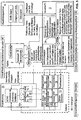
- the simulator 1 can be designed as a crane simulator, which includes a control stand 2 in the form of a crane operator's cab, which is essentially a "real" crane operator's cab, as used on a crane, for example a tower crane, a harbor crane or a maritime crane or mobile telescopic crane Can be found.
- a crane simulator which includes a control stand 2 in the form of a crane operator's cab, which is essentially a "real" crane operator's cab, as used on a crane, for example a tower crane, a harbor crane or a maritime crane or mobile telescopic crane Can be found.
- Said control station 2 can comprise, in a manner known per se, an operator's seat 21, for example in the form of an operator's chair 20, around which various input means 18 for entering control commands are arranged.
- Said input means 18 can for example have a joystick, a touchscreen, control levers, input keys and switches, rotary controls, slide controls and the like.
- a driver's cab wall 22 which can correspond to a cabin housing and can have window areas 23 that are glazed in real crane driver's cabs, but in the present case are colored in a certain color, for example coated with a green film, in order to Screen technology to be able to show a virtual machine environment, as will be explained.
- the control stand 2 is mounted on a movement platform 7, by means of which the control stand 2 can be moved in multiple axes.
- the movement platform 7 is advantageously designed to be movable in multiple axes, in particular tiltable or rotatable about all three spatial axes x, y and z and translationally displaceable along these axes.
- the movement axes x, y and z of the movement platform 7 are assigned actuators of a drive device 8, for example in the form of electric motors and / or hydraulic cylinders and / or hydraulic motors, in order to be able to move the control station 2 around or along the named axes.
- the drive device 8 is controlled by a movement control device 24, which can be implemented, for example, by an industrial PC.
- the mentioned movement control device 24 can in particular be part of a movement simulation module 10, by means of which crane movements and / or positions and / or alignments of crane components such as the boom or the tower and also twisting of structural components such as the boom or the tower depending on the respective at the control station 2 entered control commands can be determined. That said Movement simulation module 10 determines, so to speak, the effects of the input control commands on the crane to be simulated, ie which movements, positions, orientations and twists of the crane components would result on the crane to be simulated as a result of input control commands and outputs corresponding movement signals characterizing the variables mentioned.
- the mentioned movement simulation module 10 does not or does not completely determine the mentioned movement variables by calculation using a computer model, but rather uses actual hardware components in the form of drive and control components that perform actual movements and are simulated on a real crane with the corresponding hardware components.
- the movement simulation module 10 comprises at least the essential components of a crane control 25, as this can be implemented, for example, in the control cabinet of a crane.
- the named crane control 25 includes the frequency converters 15 of various crane drives, for example the slewing gear, the trolley and the hoisting gear.
- the mentioned crane control 25 can optionally include further control and / or power electronic components, in particular load monitoring components, work area restriction components, etc.
- the crane control 25 is communicatively connected to the control station 2 and its input means 18, so that the crane control 25 can further process the input control commands, the frequency converters 15 in particular controlling drive units 12, for example in the form of servo drives, depending on the input control commands.
- the control commands entered at the control station 2 are thus converted into real movements or drive torques and forces of the drive units 12.
- Said drive units 12 can be coupled to counter drive units 14, via which movement resistances can be connected to drive units 12 in order to be able to simulate real resistances such as lifting loads, wind forces, inertia or dynamic loads.
- the aforementioned counter drive units 14 can be controlled by the aforementioned industrial PC, which also implements the movement control device 24.
- the counter drive units 14 can be controlled using various specifications or programs, for example using prescribable lifting loads, prescribable wind programs or using predetermined functions or tables such as dynamic reactions when braking the trolley or the rotary movement.
- corresponding models, tables or functions can be stored in a memory module of the control device for controlling the counter drive units 14.
- the drive units 12 are assigned detection devices 13, for example in the form of rotary encoders or other position and / or movement sensors, by means of which movement or position signals are provided that characterize the actuating movements of the drive units 12.
- the movement simulation module 10 thus provides real sensor signals as movement parameters which, on the one hand, can be displayed on the control stand 2 and, on the other hand, can also be used for more extensive simulation functions.
- the movement simulation module 10 can include a computer unit 11, which in turn can be implemented by the aforementioned industrial PC, by means of which computer unit 11 as a function of the control station 2 input control commands and / or the emulated data generated by the data emulation device 19 or the sensor signals generated by the drive units 12 associated with the drive units 12, structural distortions are determined, in particular bending and torsion in the crane tower and in the crane boom, with the computer unit 11 entering the structural rigidity for this purpose used calculation model, as explained at the beginning.
- the movement control device 24 controls the drive device 8 of the movement platform 7 in order to move the control stand 2 and to simulate real crane operator cabin movements that would occur in a real crane if the corresponding control commands were entered.
- the mentioned movement data and possibly also the mentioned deformation data are used to take crane reactions into account in a virtual representation that is generated by a graphic simulation module 9 and displayed on a display device 3.
- the aforementioned virtual representation shows in particular the crane environment and the crane components visible therein, such as the crane boom and the load hook, and can essentially correspond to the image that a crane operator would see from the crane operator's cab.
- the aforementioned virtual representation can in this case correspond to a photo or film-like digital image, for example a pixel representation in several colors.
- a simplified graphic representation can also be provided, although a representation image that is as realistic as possible, photo- or film-like is preferred.
- the aforementioned virtual representation of the crane environment and the crane components visible therein is superimposed by a live image which shows real components from the control stand 2, in particular components such as the ones visible from the head of the simulator user in his direction of view Input means 18, the hands and forearms of the user and other components in the field of view.
- a camera 16 is advantageously provided, which can be designed as a head camera that can be worn on the head of the user and can have corresponding fastening and / or holding means for fastening on the head, for example in the form of a helmet camera. If the display device 3 is advantageously designed in the form of virtual reality glasses 4 that the user wears, the camera 16 can be integrated into these VR glasses.
- the camera 16 is advantageously designed as a stereoscopic camera in order to be able to provide stereoscopic images corresponding to the viewing axes of the two eyes of the user.
- the overlay device 17 for overlaying the virtual representation of the crane environment generated by the graphic simulation module 9 and the live image from the camera 16 can in particular include a color-based image processing module 26 that can work according to the so-called green screen technology.
- the named color-based image processing module 26 can recognize image areas in the live image of the camera 16 that have a specific color that differs from the remaining partial image areas, and then replace these image areas with the virtual representation from the simulation module 9.
- control station 2 can advantageously comprise a driver's cab wall 22 in which window areas 23 - for example corresponding to the viewing windows of a real crane driver's cab - are colored in a key color that differs from the remaining colors of the other components in the camera's field of view, such as the color of the window frames Input means 18 and the operator's clothing and skin color as clearly as possible, so that the live image recorded in the control stand 2 shows the mentioned colored areas in a specific color rendering, while all other picture areas are shown in different colors.
- window areas 23 - for example corresponding to the viewing windows of a real crane driver's cab - are colored in a key color that differs from the remaining colors of the other components in the camera's field of view, such as the color of the window frames Input means 18 and the operator's clothing and skin color as clearly as possible, so that the live image recorded in the control stand 2 shows the mentioned colored areas in a specific color rendering, while all other picture areas are shown in different colors.
- the live image areas or partial areas colored in the key color mentioned - for example green - are then replaced by the virtual representation of the machine environment and / or the machine components visible therein, which is generated by the graphic simulation module 9, so that the overlaid image or representation on the one hand shows the control station 2 of the simulator, its components and the limbs of the user located in the field of view of the live camera in real life as a live image and on the other hand shows the virtual representation of the machine environment and the machine components visible therein in the window areas 23 of the driver's cab wall 22 recorded by the live camera 16.
- Said virtual representation of the machine environment can advantageously be changed by the graphic simulation module 9 and adapted to various scenarios as a function of various data records that can be imported into the simulation module via an interface.
- planning data such as CAD data of a building to be manufactured and / or actual construction site data and / or image data, which reflect the actual state of a building or structure depending on the construction progress, can be made via a corresponding data interface, for example a CAD interface and / or an image data interface, are imported into the simulation module 9 and used by the simulation module 9 to generate or adapt the virtual representation of the machine environment according to the imported data record, in particular depending on the imported planning data and / or actual construction site data.
Description
Die vorliegende Erfindung betrifft einen Simulator für einen Kran, eine Baumaschine oder ein Flurförderzeug, mit einem Steuerstand, der zumindest ein Eingabemittel zum Eingeben von Steuerbefehlen aufweist, einem grafischen Simulationsmodul zum Berechnen einer virtuellen Darstellung der Maschinenumgebung und/oder von aus dem Steuerstand sichtbaren Maschinenkomponenten wie Ausleger oder Lasthaken, sowie einer Anzeigevorrichtung zum Anzeigen der berechneten virtuellen Darstellung, wobei ein Bewegungssimulationsmodul zum Bestimmen von Bewegungen und/oder Verformungen der Maschinenkomponenten in Abhängigkeit der eingegebenen Steuerbefehle vorgesehen ist, in Abhängigkeit derer das grafische Simulationsmodul die virtuelle Darstellung berechnet.The present invention relates to a simulator for a crane, a construction machine or an industrial truck, with a control stand which has at least one input means for entering control commands, a graphic simulation module for calculating a virtual representation of the machine environment and / or machine components visible from the control stand such as Boom or load hook, as well as a display device for displaying the calculated virtual representation, with a motion simulation module for determining movements and / or deformations of the machine components depending on the input control commands, depending on which the graphic simulation module calculates the virtual representation.
Krane und ähnliche Großgeräte wie Bohrrammgeräte, Surface Miner oder Seilbagger sind in der Bedienung und Steuerung sehr komplex und daher schwierig zu erlernen, so dass übliche Schulungs- und Lehrmaterialien wie Fotos, Pläne oder auch Filme nicht ausreichen, um die Bedienung und Überwachung tatsächlich anschaulich zu vermitteln und leicht erlernbar zu machen. Dabei ist nicht nur die Vielzahl der Steuerungsfunktionen und deren Zusammenwirken sowie die damit einhergehenden, in ihrer Gesamtheit recht komplexen Eingabemittel wie Joysticks, Fußpedale und Steuerungsschalter ein Problem, sondern auch die oft ungewohnten, maschinenspezifischen Reaktionen der Maschinenstruktur auf Bewegungen der Stellantriebe. Krane wie beispielsweise Turmdrehkrane oder Teleskop-Wippkrane, aber auch Hafen- oder Maritimkrane besitzen lange, schlanke Strukturbauteile wie Ausleger- oder Turmstrukturen, die sich verwinden und relativ weich sind, so dass mit Beschleunigungs- oder Abbremsvorgängen der Stellantriebe Strukturverformungen und Pendelbewegungen einhergehen, die eine sichere Bedienung auch für erfahrene Kranführer erschweren, wenn diese auf einen neuen Krantyp umsteigen. Anders als bei Kleingeräten mit näherungsweise als starr anzunehmenden Strukturen kann es beispielsweise bei Turmdrehkranen zu Verformungen der Turmstruktur und des Auslegersystems kommen, wenn eine Last aufgenommen wird, oder es kann die Last beim Drehen um die aufrechte Achse nachpendeln und der Ausleger dementsprechend rotatorisch nachschwingen. Ähnliches kann bei Seilbaggern oder Bohrrammgeräten auftreten, so dass ein Kranführer bzw. Maschinenführer unsicher wird, wenn er die in der Theorie zwar sicher erlernten Steuervorgänge in der Praxis anwendet und die entsprechenden Kranreaktionen erfährt.Cranes and similar large devices such as hammer drills, surface miners or rope shovels are very complex to operate and control and therefore difficult to learn, so that common training and teaching materials such as photos, plans or even films are not sufficient to actually make operation and monitoring clear convey and make it easy to learn. This is not just about the multitude of control functions and their interaction as well as the associated ones The associated, in their entirety quite complex input means such as joysticks, foot pedals and control switches are a problem, but also the often unfamiliar, machine-specific reactions of the machine structure to movements of the actuators. Cranes such as tower cranes or telescopic luffing cranes, but also harbor or maritime cranes have long, slim structural components such as jib or tower structures that twist and are relatively soft, so that acceleration or braking processes of the actuators are accompanied by structural deformations and pendulum movements make safe operation even more difficult for experienced crane operators when they switch to a new type of crane. In contrast to small devices with structures that can be assumed to be more or less rigid, the tower structure and the boom system can, for example, deform the tower structure and the boom system when a load is picked up, or the load can oscillate when rotating around the upright axis and the boom can oscillate accordingly. Something similar can occur with rope excavators or hammer drills, so that a crane operator or machine operator becomes unsure if he applies the control processes that have been safely learned in theory in practice and experiences the corresponding crane reactions.
Um die Schulung und das Training realitätsnäher zu gestalten, wurde daher bereits der Einsatz von Kransimulatoren vorgeschlagen, in denen der zu trainierende Kranführer in einem näherungsweise realistischen Steuerstand, der beispielsweise der Kranführerkabine eines jeweiligen Krantyps entsprechen kann, über dort vorgesehene Eingabemittel wie Joysticks, Pedale, Steuerschalter oder Touchscreens Steuerbefehle eingeben kann, um die Kranreaktionen auf diese Steuerbefehle möglichst realitätsnah zu erfahren, vgl.
Wird beispielsweise der Kran um die aufrechte Achse verdreht bzw. ein entsprechender Steuerbefehl eingegeben, berechnet das grafische Simulationsmodul die Darstellung der Kranumgebung derart, dass diese auf dem Bildschirm von rechts nach links bzw. umgekehrt wandert, so dass die auf der Anzeigevorrichtung dargestellte virtuelle Kranumgebung am Kranführer in ähnlicher Weise vorbeiwandert, wie dies bei einem "echten" Verdrehen eines Krans in dessen Krankabine erfolgt. Wird andererseits ein Steuerbefehl eingegeben, der beispielsweise den Lasthaken absenkt und/oder den Ausleger abwippt, verändert das grafische Simulationsmodul die virtuelle Darstellung derart, dass der Kranhaken auf der Anzeigevorrichtung nach unten wandert bzw. der Ausleger abwippt. Durch eine solche realitätsnahe Simulation des Kranbetriebs bekommt der Kranführer leichter ein Gespür dafür, was die Reaktionen auf eine Betätigung der Eingabemittel des Steuerstands sind.If, for example, the crane is rotated around the upright axis or a corresponding control command is entered, the graphic simulation module calculates the representation of the crane environment in such a way that it moves on the screen from right to left or vice versa, so that the virtual crane environment shown on the display device is on The crane operator wanders past in a similar way to what happens when a crane is "real" twisted in its crane cabin. If, on the other hand, a control command is entered which, for example, lowers the load hook and / or rocks the boom, the graphic simulation module changes the virtual representation in such a way that the crane hook moves downwards on the display device or the boom rocks. Such a realistic simulation of the crane operation gives the crane operator a sense of what the reactions are to an actuation of the input means of the control station.
Ein solcher Kransimulator ist beispielsweise aus der Schrift
Bei diesem vorbekannten Kransimulator ist die Realitätsnähe der virtuellen Darstellung jedoch noch begrenzt. Zum einen kann es durch die komplexen Rechenvorgänge, die für die Bestimmung des dynamischen Verhaltens notwendig sind, zu einem verzögerten Ansprechverhalten bzw. einer gegenüber den tatsächlichen, in Echtzeit erfolgenden Kranreaktionen verzögerten Darstellung der virtuellen Kranrealität kommen, insbesondere wenn mehrere Stellbewegungen gleichzeitig virtuell umzusetzen sind. Zum anderen ist die intuitive Erspürbarkeit der Kranreaktionen auf bestimmte Steuerbefehle durch die auf den Bildschirmen erzeugbaren Darstellungen der virtuellen Kranumgebung begrenzt.In this previously known crane simulator, however, the realism of the virtual representation is still limited. On the one hand, the complex computing processes that are necessary to determine the dynamic behavior can lead to a delayed response behavior or a representation of the virtual crane reality that is delayed compared to the actual crane reactions taking place in real time, especially if several actuating movements are to be implemented virtually at the same time. On the other hand is the intuitive perceptibility of the Crane reactions to certain control commands are limited by the representations of the virtual crane environment that can be generated on the screens.
Hiervon ausgehend liegt der vorliegenden Erfindung die Aufgabe zugrunde, einen verbesserten Simulator der eingangs genannten Art zu schaffen, der Nachteile des Standes der Technik vermeidet und Letzteren in vorteilhafter Weise weiterbildet. Insbesondere soll eine realitätsnähere Simulation des Kran- bzw. Maschinenbetriebs erreicht werden, die den Trainingseffekt verbessert und das tatsächliche Kran- bzw. Maschinenverhalten besser vermittelt und leichter erlernbar macht.Proceeding from this, the present invention is based on the object of creating an improved simulator of the type mentioned at the beginning, which avoids the disadvantages of the prior art and further develops the latter in an advantageous manner. In particular, a more realistic simulation of the crane or machine operation is to be achieved, which improves the training effect and communicates the actual crane or machine behavior better and makes it easier to learn.
Erfindungsgemäß wird die genannte Aufgabe durch einen Simulator gemäß Anspruch 1 gelöst. Bevorzugte Ausgestaltungen der Erfindung sind Gegenstand der abhängigen Ansprüche.According to the invention, the stated object is achieved by a simulator according to claim 1. Preferred embodiments of the invention are the subject of the dependent claims.
Es wird also eine Datenemulation unter Verwendung von Hardwarekomponenten vorgeschlagen, die tatsächliche Stellbewegungen ausführen und somit "echte" Stellbewegungen der zu simulierenden Maschine nachbilden, um entsprechende Bewegungsdaten schneller und mit weniger Rechenleistung bereitzustellen, wodurch in Echtzeit oder nahezu Echtzeit eine realistischere Simulation erreicht werden kann. Dabei kann der Simulator die für die Bewegungssimulation benötigten Bewegungsparameter nicht alle von einem Simulationsrechner berechnen lassen, sondern zumindest teilweise im Wege der Datenemulation unter Verwendung von sich tatsächlich bewegenden Hardwarekomponenten, die einen Bestandteil des Simulators bilden können, bestimmen. Ein solches Datenemulationsmodul des Simulators kann insbesondere Stellantriebskomponenten und/oder Leistungselektronikkomponenten umfassen, mittels derer tatsächlich Stellbewegungen ausgeführt werden, die die echten Kran- bzw. Maschinenbewegungen nachbilden und diese Bewegungen charakterisierende Daten bereitstellen, beispielsweise in Form von Sensorsignalen, die die Stellbewegungen der genannten Antriebskomponenten wiedergeben. Durch eine solche Datenemulation können Bewegungs- und/oder Positionsparameter, die dann für die Bewegungssimulation weiter verwendet werden können, deutlich schneller und unter geringerer Rechenleistung bereitgestellt werden, was eine realistischere Simulation in Echtzeit bzw. nahezu Echtzeit erlaubt.It is therefore proposed a data emulation using hardware components that carry out actual positioning movements and thus simulate "real" positioning movements of the machine to be simulated in order to provide corresponding movement data faster and with less computing power, whereby a more realistic simulation can be achieved in real time or almost real time. The simulator cannot have all of the motion parameters required for the motion simulation calculated by a simulation computer, but can at least partially determine them by means of data emulation using actually moving hardware components that can form part of the simulator. Such a data emulation module of the simulator can in particular include actuator components and / or power electronics components, by means of which actuating movements are actually carried out that simulate the real crane or machine movements and provide data characterizing these movements, for example in the form of sensor signals that reproduce the actuating movements of the drive components mentioned . Such a data emulation allows movement and / or position parameters that can then be used further for the motion simulation, are provided significantly faster and with less computing power, which allows a more realistic simulation in real time or almost real time.
Um eine besonders schnelle, realistische Bestimmung von Bewegungen der Maschinenkomponenten in Abhängigkeit der am Steuerstand eingegebenen Steuerbefehle zu erreichen, kann nach einem weiteren Aspekt das genannte Bewegungssimulationsmodul als Hybrideinrichtung bzw. Hybridmodul ausgebildet sein, das einerseits einen Rechner zur Simulation von Bewegungs- und/oder Positionsparametern und andererseits den echten Kran- bzw. Maschinenstellantrieben zumindestens ähnliche Hardwarekomponenten wie Antriebseinheiten, Drehgeber oder Frequenzumrichter umfasst, mittels derer Stellbewegungen nachgebildet und Bewegungs- und/oder Positionsparameter bestimmt werden. Insbesondere werden "echte" Hardwarekomponenten verwendet, die auch im zu simulierenden Kran bzw. der zu simulierenden Maschine als Stellantriebs- und/oder Steuervorrichtungsbauteile verbaut sind.In order to achieve a particularly fast, realistic determination of movements of the machine components as a function of the control commands entered at the control station, according to a further aspect, the mentioned movement simulation module can be designed as a hybrid device or hybrid module, which on the one hand has a computer for simulating movement and / or position parameters and on the other hand, the real crane or machine actuators include at least similar hardware components such as drive units, rotary encoders or frequency converters, by means of which actuating movements are simulated and movement and / or position parameters are determined. In particular, "real" hardware components are used which are also built into the crane to be simulated or the machine to be simulated as actuator and / or control device components.
Insbesondere kann das Bewegungssimulationsmodul den Schaltschrank oder zumindest einen Teil des Schaltschranks und dessen Komponenten umfassen, der auch in der zu simulierenden Maschine Verwendung findet und dort einen Teil der Maschinensteuerung bildet. Insbesondere kann die Leistungselektronik und/oder zumindest ein Teil der Leistungselektronik wie beispielsweise ein Frequenzumrichter verwendet werden, um die Stellbewegungen nachzubilden, die von Steuerbefehlseingaben am Steuerstand ausgelöst werden.In particular, the movement simulation module can include the switch cabinet or at least a part of the switch cabinet and its components, which is also used in the machine to be simulated and forms part of the machine control there. In particular, the power electronics and / or at least some of the power electronics, such as a frequency converter, can be used to simulate the positioning movements that are triggered by control command inputs at the control station.
Gemäß der Erfindung finden Stellantriebseinheiten, beispielsweise in Form von Servomotoren Verwendung finden, die der Emulation der Stellantriebsbewegungen der zu simulierenden Maschine bzw. Maschinenkomponenten dienen. Dabei wird für eine jeweilige Stellantriebsachse eine Antriebseinheit beispielsweise in Form einer Servoantriebseinheit verwendet, die - insbesondere über den vorgenannten Frequenzumrichter - entsprechend einem Steuerbefehl angesteuert wird, und ferner mit einer weiteren Antriebseinheit, beispielsweise in Form einer Servoantriebseinheit, gekuppelt wird, mittels derer ein Gegenmoment und/oder eine Gegenlast ausgeübt werden kann, um tatsächlich auftretende Lasten, Widerstände oder Trägheiten zu simulieren. Beispielsweise kann mittels der genannten zweiten Antriebseinheit eine Last simuliert werden, die einem Hubwerk entgegenwirkt, oder es kann ein Windmoment simuliert werden, das einem Drehwerksantrieb entgegenwirkt.According to the invention, actuator units are used, for example in the form of servomotors, which are used to emulate the actuator movements of the machine or machine components to be simulated. In this case, a drive unit, for example in the form of a servo drive unit, is used for a respective actuator axis, which - in particular via the aforementioned frequency converter - is controlled in accordance with a control command, and is also coupled to a further drive unit, for example in the form of a servo drive unit, by means of which a counter-torque and / or a counter-load can be exerted in order to simulate actually occurring loads, resistances or inertia. For example, by means of said second drive unit, a load can be simulated which counteracts a lifting mechanism, or a wind moment can be simulated which counteracts a slewing mechanism drive.
Die ggf. unter Berücksichtigung des aufgebrachten Gegenmoments oder der aufgebrachten Gegenlast ausgeführte Stellbewegung der erstgenannten Antriebseinheit kann von einer geeigneten Erfassungseinrichtung erfasst werden, wobei ein entsprechendes Erfassungssignal die tatsächlich erzielte Stellbewegung wiedergibt und als Sensorsignal in der weiteren Simulation verwendet werden kann, insbesondere um in der vorgenannten Weise Bewegungen und/oder Positionen und/oder Verformungen der Strukturteile zu bestimmen und/oder die virtuelle Darstellung der Maschinenumgebung und/oder der darin sichtbaren Maschinenkomponenten zu simulieren.The adjusting movement of the first-mentioned drive unit, possibly taking into account the applied counter-torque or the applied counter-load, can be recorded by a suitable detection device, with a corresponding detection signal reproducing the actually achieved adjusting movement and being used as a sensor signal in the further simulation, in particular in the aforementioned Way to determine movements and / or positions and / or deformations of the structural parts and / or to simulate the virtual representation of the machine environment and / or the machine components visible therein.
Vorteilhafterweise werden mehrere solcher Antriebseinheiten bzw. mehrere solcher Antriebseinheiten-Paare umfassend Antrieb und Gegenlast-Antrieb sowie eine jeweils zugeordnete Erfassungseinrichtung verwendet, um die verschiedenen Stellbewegungs-Achsen und die diesbezüglich ausgeführten Stellbewegungen des zu simulierenden Maschinenbetriebs bestimmen zu können.Advantageously, several such drive units or several such drive unit pairs comprising drive and counter-load drive as well as a respective associated detection device are used to determine the various adjustment movement axes and the related adjustment movements of the machine operation to be simulated.
Die Sensorwerte der Antriebseinheiten der Stellbewegungsachsen, die in Abhängigkeit der am Steuerstand eingegebenen Steuerbefehle betätigt und bewegt werden, werden also nach einem weiteren Aspekt nicht mittels eines Rechenmodells simuliert bzw. berechnet, sondern anhand von Hardwarekomponenten, die den echten Stellantriebskomponenten der zu simulierenden Maschine möglichst nahe kommen, emuliert bzw. nachgestellt und direkt als tatsächliche Sensorwerte ausgegeben.According to a further aspect, the sensor values of the drive units of the actuating movement axes, which are actuated and moved depending on the control commands entered at the control station, are not simulated or calculated using a computer model, but rather using hardware components that are as close as possible to the real actuator components of the machine to be simulated come, emulated or readjusted and output directly as actual sensor values.
Durch ein solches Daten-Emulationssystem kann das Bewegungssimulationsmodul Bewegungen und/oder Positionen der Maschinenkomponenten sehr viel schneller und mit geringerer Rechenleistung bestimmen, so dass die virtuelle Darstellung der Maschinenumgebung und/oder der Maschinenkomponenten und auch die damit einhergehenden Stellbewegungen des Maschinenstands sehr viel rascher und realitätsnaher erreicht werden können. Zudem können die generierten Sensorsignale am Steuerstand angezeigt und/oder für weitere Überwachungsmassnahmen wie Traglastüberwachung oder Arbeitsbereichs-Begrenzungen, die am Steuerstand angezeigt und/oder simuliert werden können, verwendet werden.With such a data emulation system, the motion simulation module can determine movements and / or positions of the machine components much faster and with less computing power, so that the virtual representation of the machine environment and / or the machine components and the associated positioning movements of the machine status are much quicker and more realistic can be achieved. In addition, the generated sensor signals can be displayed at the control stand and / or used for further monitoring measures such as load monitoring or work area limitations that can be displayed and / or simulated at the control stand.
Wird der Kransimulator zur Simulation eines Turmdrehkrans und dessen Betriebs verwendet, können die vorgenannten Antriebseinheiten-Paare zum Ausführen der entsprechenden Stellbewegungen und Bereitstellen des entsprechenden Gegenmoments bzw. Gegenlast insbesondere dem Turmdrehwerk - bzw. bei einem Obendreher dem Auslegerdrehwerk -, dem Hubwerk und dem Katzfahrwerk entsprechen.If the crane simulator is used to simulate a tower crane and its operation, the aforementioned pairs of drive units can correspond to the tower slewing gear - or, in the case of a top slewing, the boom slewing gear -, the hoist gear and the trolley for executing the corresponding adjusting movements and providing the corresponding counter-torque or counter-load .
Nach einem weiteren Aspekt ist das Bewegungssimulationsmodul derart ausgebildet, dass die Kran- bzw. Maschinenstruktur nicht als starre, sozusagen unendlich steife Struktur betrachtet wird, sondern als elastisch verformbare und/oder nachgiebige und/oder relativ weiche Struktur angenommen wird, die - zusätzlich zu den Stellbewegungsachsen der Maschine wie beispielsweise der Auslegerwippachse oder der Turmdrehachse - Bewegungen und/oder Positionsänderungen durch Verformungen der Strukturbauteile zulässt. Die Berücksichtigung der Beweglichkeit der Maschinenstruktur infolge von Strukturverformungen unter Last oder dynamischen Belastungen ist gerade bei langgestreckten, schlanken und von den statischen und dynamischen Randbedingungen her bewusst - unter Berücksichtigung der notwendigen Sicherheiten - ausgereizten Strukturen wie bei Kranen von Bedeutung, da hier spürbare Bewegungsanteile beispielsweise für die Kranführerkabine, aber auch die Lasthakenposition durch die Verformungen der Strukturbauteile hinzukommen. Um hier eine tatsächlich realistische Schulung bzw. ein realitätsnahes Training ermöglichen zu können, berücksichtigt das Bewegungssimulationsmodul solche Verformungen der Maschinenstruktur unter statischen oder dynamischen Belastungen.According to a further aspect, the movement simulation module is designed in such a way that the crane or machine structure is not viewed as a rigid, so to speak infinitely rigid structure, but rather as an elastically deformable and / or flexible and / or relatively soft structure that - in addition to the Adjustment movement axes of the machine such as the boom luffing axis or the tower rotation axis - allows movements and / or changes in position due to deformation of the structural components. Taking into account the mobility of the machine structure as a result of structural deformations under load or dynamic loads is particularly important in the case of elongated, slim structures that are deliberately exhausted from the static and dynamic boundary conditions - taking into account the necessary safety factors - such as cranes, since here noticeable movement components, for example the crane operator's cab, but also the load hook position due to the deformation of the structural components. Around To enable an actually realistic training or a realistic training, the motion simulation module takes into account such deformations of the machine structure under static or dynamic loads.
Insbesondere kann die Bestimmungseinrichtung zur Bestimmung solcher Strukturverformungen eine Berechnungseinheit aufweisen, die diese Strukturverformungen anhand eines gespeicherten Berechnungsmodells in Abhängigkeit der am Steuerstand eingegebenen Steuerbefehle berechnet. Ein solches Modell kann ähnlich einem Finite-Elemente-Modell aufgebaut sein oder ein Finite-Elemente-Modell sein, wobei vorteilhafterweise jedoch ein gegenüber einem Finite-Elemente-Modell deutlich vereinfachtes Modell verwendet wird, das beispielsweise empirisch durch Erfassung von Strukturverformungen unter bestimmten Steuerbefehlen und/oder Belastungszuständen am echten Kran bzw. der echten Maschine bestimmt werden kann. Ein solches Berechnungsmodell kann beispielsweise mit Tabellen arbeiten, in denen bestimmten Steuerbefehlen bestimmte Verformungen zugeordnet sind, wobei Zwischenwerte der Steuerbefehle mittels einer Interpolationsvorrichtung in entsprechende Verformungen umgerechnet werden können.In particular, the determination device for determining such structural deformations can have a calculation unit which calculates these structural deformations on the basis of a stored calculation model as a function of the control commands entered at the control station. Such a model can be constructed similarly to a finite element model or a finite element model, but advantageously a model that is significantly simplified compared to a finite element model is used which, for example, empirically by detecting structural deformations under certain control commands and / or load conditions on the real crane or the real machine can be determined. Such a calculation model can work, for example, with tables in which certain control commands are assigned certain deformations, with intermediate values of the control commands being able to be converted into corresponding deformations by means of an interpolation device.
Die Verwendung eines solchen gegenüber einem Finite-Elemente-Modell vereinfachten Berechnungsmodells erlaubt eine zeitlich schnellere Bestimmung der Strukturverformungen und damit eine realitätsnähere Simulation von Maschinenbewegungen in Echtzeit bzw. nahezu Echtzeit unter weniger Rechenleistung.The use of such a calculation model, which is simplified compared to a finite element model, allows the structural deformations to be determined more quickly and thus a more realistic simulation of machine movements in real time or almost real time with less computing power.
Die vom Bewegungssimulationsmodul berücksichtigten Strukturteilverformungen können einerseits bei der Ansteuerung der Antriebsvorrichtung zum Bewegen des Steuerstands berücksichtigt werden, so dass der Steuerstand die durch die Strukturteilverformungen auftretenden Steuerstandbewegungen nachbildet. Alternativ oder zusätzlich können die bestimmten Strukturteilverformungen auch bei der Berechnung der virtuellen Darstellung der Maschinenumgebung und/oder der darin sichtbaren Maschinenkomponenten berücksichtigt werden, beispielsweise dahingehend, dass in der virtuellen Darstellung die Durchbiegung des Auslegers dargestellt wird oder der Horizont der Kranumgebung ein Stück nach oben gefahren wird, um ein leichtes Nach-vorne-Nicken der Kranführerkabine durch beispielsweise eine Turmverformung nachzubilden.The structural part deformations taken into account by the movement simulation module can on the one hand be taken into account when activating the drive device for moving the control stand, so that the control stand simulates the control stand movements that occur as a result of the structural part deformations. As an alternative or in addition, the determined structural part deformations can also be used when calculating the virtual representation of the machine environment and / or the machine components visible therein are taken into account, for example to the effect that the deflection of the boom is shown in the virtual representation or the horizon of the crane environment is moved up a little in order to simulate a slight forward nod of the crane operator's cab, for example by deforming the tower.
Nach einem weiteren Aspekt wird vorgeschlagen, Kran- bzw. Maschinenreaktionen auf am Steuerstand eingegebene Steuerbefehle beispielsweise in Form von Kranbewegungen und/oder -verformungen nicht nur in Form einer virtuellen Darstellung auf der Anzeigevorrichtung darzustellen, sondern in eine mit der Kran- bzw. Maschinenreaktion einhergehende, tatsächliche Bewegung des Steuerstands umzusetzen, um dem Simulator-Nutzer die dynamischen Maschinenreaktionen realitätsnäher zu vermitteln und erfahren zu lassen. Der Steuerstand, der beispielsweise einen Bedienersessel umfassen kann, ist hierzu nicht mehr statisch starr im Raum, bzw. am Boden montiert, sondern von einer Antriebsvorrichtung im Raum bewegbar.According to a further aspect, it is proposed to display crane or machine reactions to control commands entered at the control station, for example in the form of crane movements and / or deformations, not only in the form of a virtual representation on the display device, but also in one associated with the crane or machine reaction to implement actual movement of the control station in order to convey and experience the dynamic machine reactions more realistically to the simulator user. For this purpose, the control stand, which can comprise an operator's chair, is no longer statically rigid in the room or mounted on the floor, but can be moved in the room by a drive device.
Insbesondere ist der Steuerstand beweglich gelagert und von einer Antriebsvorrichtung in Abhängigkeit der von dem Bewegungs-simulationsmodul bestimmten Bewegungen und/oder Verformung der Maschinenkomponenten bewegbar. Bestimmt das Bewegungssimulationsmodul Auslenkungen von Maschinenkomponenten wie beispielsweise des Kranturms durch Stellbewegungen oder Verformungen, die auf die Position der echten Kranführerkabine Einfluss hätten, wird die Antriebsvorrichtung von einer Antriebssteuervorrichtung entsprechend angesteuert, um die Bewegung der Kranführerkabine nachzubilden und den Steuerstand entsprechend zu bewegen. Wird beispielsweise am Steuerstand ein Befehl zum Verdrehen des Krans um eine aufrechte Achse eingegeben, wird der Steuerstand von der Antriebsvorrichtung entsprechend um die aufrechte Achse verdreht. Wird beispielsweise der Steuerbefehl zum Anheben einer schweren Last eingegeben, was in der Realität zu einem leichten Nicken der Kranstruktur unter leichter Verwindung des Turms führen kann, wird der Steuerstand von der Antriebsvorrichtung leicht nach vorne verfahren und/oder leicht nach vorne verkippt.In particular, the control stand is movably mounted and can be moved by a drive device as a function of the movements and / or deformation of the machine components determined by the movement simulation module. If the motion simulation module determines deflections of machine components such as the crane tower by adjusting movements or deformations that would affect the position of the real crane driver's cab, the drive device is controlled accordingly by a drive control device in order to simulate the movement of the crane driver's cab and move the control station accordingly. If, for example, a command to rotate the crane about an upright axis is entered at the control stand, the control stand is correspondingly rotated about the upright axis by the drive device. If, for example, the control command to lift a heavy load is entered, which in reality can lead to a slight pitching of the crane structure with a slight twisting of the tower, the Move the control station slightly forwards from the drive device and / or tilt it slightly forwards.
Um eine möglichst realitätsnahe Nachbildung der im echten Betrieb auftretenden Steuerstandbewegungen zu ermöglichen, kann die Antriebsvorrichtung mehrachsig bewegbar ausgebildet sein und/oder sowohl rotatorische als auch translatorische Bewegungen ausführen. Insbesondere kann der Steuerstand mehrachsig beweglich gelagert sein und die Antriebsvorrichtung zumindest eine aufrechte Drehachse und zumindest eine liegende Wippachse und/oder zwei liegend ausgerichtete Translationsachsen umfassen. Um auch komplexe Steuerstandsbewegungen nachbilden zu können, kann die Antriebsvorrichtung drei Rotations- bzw. Kippachsen aufweisen bzw. dreiachsig rotatorisch arbeitend ausgebildet sein und dreiachsig translatorisch arbeitend ausgebildet sein, so dass der Steuerstand um alle drei Raumachsen verdreht bzw. verkippt und in alle drei Raumrichtungen translatorisch verfahren werden kann. Je nach zu simulierendem Kran- bzw. Maschinentyp können auch einfachere Ausbildungen der Antriebsvorrichtung mit weniger Bewegungsachsen in Betracht kommen.In order to allow the control station movements that occur in real operation to be simulated as realistically as possible, the drive device can be designed to be movable in multiple axes and / or can perform both rotary and translational movements. In particular, the control station can be mounted so as to be movable in multiple axes and the drive device can comprise at least one upright axis of rotation and at least one horizontal tilting axis and / or two horizontally oriented translation axes. In order to also be able to simulate complex control station movements, the drive device can have three axes of rotation or tilting or can be designed to work in rotation in three axes and to work in translation on three axes, so that the control station rotates or tilts around all three spatial axes and translationally in all three spatial directions can be proceeded. Depending on the type of crane or machine to be simulated, simpler designs of the drive device with fewer axes of movement can also be considered.
Um das Realitätsempfinden des Nutzers des Simulators weiter zu erhöhen, ist nach einem weiteren Aspekt vorgesehen, dass auf der Anzeigevorrichtung die von dem grafischen Simulationsmodul bereitgestellten virtuellen Darstellungen aus der Simulationswelt mit Livebildern aus dem Steuerstand, die beispielsweise Bewegungen des Simulator-Nutzers zeigen können, überlagert werden. Insbesondere können auf der Anzeigevorrichtung einerseits die vom grafischen Simulationsmodul generierten virtuellen Darstellungen der Maschinenumgebung und/oder der darin sichtbaren Maschinenkomponenten und andererseits am Steuerstand aufgenommene Livebilder einer Livekamera gleichzeitig und überlagert dargestellt werden. Eine solche Überlagerung von Bildern aus der Simulationswelt und Livebildern gibt dem Simulatornutzer ein besonders starkes Gefühl der Realitätsnähe.In order to further increase the simulator's sense of reality, a further aspect provides that the virtual representations from the simulation world provided by the graphic simulation module are superimposed on the display device with live images from the control station, which can show movements of the simulator user, for example become. In particular, on the one hand, the virtual representations of the machine environment and / or the machine components visible therein generated by the graphic simulation module and, on the other hand, live images of a live camera recorded at the control station can be displayed simultaneously and superimposed on the display device. Such a superposition of images from the simulation world and live images gives the simulator user a particularly strong feeling of closeness to reality.
Vorteilhafterweise kann hierzu als Anzeigevorrichtung eine am Kopf tragbare, insbesondere brillenartig ausgebildete Anzeigevorrichtung beispielsweise in Form einer Virtual-Reality-Brille und eine vorteilhafterweise ebenfalls am Kopf tragbare, beispielsweise als Helmkamera ausgeführte oder in die genannte Virtual-Reality-Brille integrierte Kamera Verwendung finden, die die genannten Livebilder bereitstellt, die zusammen mit der künstlich generierten, virtuellen Darstellung auf der Anzeigevorrichtung, insbesondere der Virtual-Reality-Brille, dargestellt werden.Advantageously, a display device which can be worn on the head, in particular a glasses-like display device, for example in the form of virtual reality glasses, and a camera which is advantageously also wearable on the head, for example designed as a helmet camera or integrated in the aforementioned virtual reality glasses, can be used as the display device provides the live images mentioned, which are displayed together with the artificially generated, virtual representation on the display device, in particular the virtual reality glasses.
Die genannte Kamera für die Bereitstellung der Livebilder kann vorteilhafterweise eine Stereoskopkamera sein, die stereoskopische Bilder vorzugswesie in zumindest näherungsweise mit der Blickrichtung des Augenpaars eines Nutzers übereinstimmender Kamerablickrichtung bereitstellt, welche an entsprechender Stelle der Anzeigevorrichtung, insbesondere der Virtual-Reality-Brille eingeblendet werden können. Hierdurch kann ein besonders realitätsnahes Nutzerempfinden erreicht werden.Said camera for providing the live images can advantageously be a stereoscopic camera, which preferably provides stereoscopic images in a camera viewing direction which at least approximately corresponds to the viewing direction of the pair of eyes of a user and which can be displayed at the appropriate point on the display device, in particular the virtual reality glasses. In this way, a particularly realistic user experience can be achieved.
Grundsätzlich wäre es aber auch möglich, Bilder aus der Simulationswelt und die genannten Livebilder auf einem an sich herkömmlichen Bildschirm zu überlagern, wobei hier beispielsweise ein Nutzer eine Livebildkamera am Kopf tragen könnte, die zumindest näherungsweise der Blickrichtung des Nutzers entsprechende Bilder bereitstellt, so dass auf der Anzeigevorrichtung beispielsweise in Form mehrerer Bildschirme dann auch ein live aufgenommener Benutzerarm bzw. der live aufgenommene Teil des Steuerstands eingeblendet werden kann. Eine realitätsnähere und damit eindrücklicher aufnehmbare Simulation kann jedoch durch Überlagerung auf den Sichtflächen eienr Virtual Reality Brille erreicht werden.In principle, however, it would also be possible to superimpose images from the simulation world and the live images mentioned on a conventional screen, in which case, for example, a user could wear a live image camera on his head that provides images that at least approximately correspond to the user's line of sight, so that on the display device, for example in the form of several screens, can then also display a live recorded user arm or the live recorded part of the control station. A more realistic and thus more impressive, recordable simulation can, however, be achieved by superimposing it on the visible surfaces of virtual reality glasses.
Die Überlagerungseinrichtung zum Überlagern der Livebilder der Kamera mit der virtuellen Darstellung aus dem grafischen Simulationsmodul kann vorteilhafterweise nach der sog. Green-Screen-Technik arbeitend ausgebildet sein, wobei die Überlagerungseinrichtung in dem Livebild Farbflächen einer vorbestimmten Farbe erkennt und diese Bildbereiche dann durch die virtuelle Darstellung aus dem Simulationsmodul ersetzt. Hierzu kann vorteilhafterweise der Steuerstand eine Führerkabinenwandung umfassen, in der Fensterbereiche - beispielsweise entsprechend den Sichtfenstern einer echten Kranführerkabine - in einer Schlüsselfarbe eingefärbt sind, die sich von den restlichen Farben der übrigen im Kamerablickfeld liegenden Komponenten wie beispielsweise der Farbe der Fenstereinrahmungen, der Eingabemittel und der Bediener-Bekleidung sowie - Hautfarbe möglichst deutlich unterscheidet, so dass das im Steuerstand aufgenommene Livebild die genannten eingefärbten Flächen in einer bestimmten Farbwiedergabe zeigt, während alle anderen Bildflächen in anderen Farben gezeigt sind. Die in der genannten Schlüsselfarbe - beispielsweise grün - gefärbten Livebildflächen bzw. -teilflächen werden dann durch die virtuelle Darstellung der Maschinenumgebung und/oder der darin sichtbaren Maschinenkomponenten ersetzt, so dass das überlagerte Bild bzw. die überlagerte Darstellung einerseits den Steuerstand des Simulators, dessen Komponenten und sich im Sichtfeld der Livekamera befindliche Körperglieder des Nutzers in echt als Livebild zeigt und andererseits in den von der Livekamera aufgenommenen Fensterbereichen der Führerkabinenwandung die virtuelle Darstellung der Maschinenumgebung und der darin sichtbaren Maschinenkomponenten zeigt.The overlay device for overlaying the live images from the camera with the virtual representation from the graphic simulation module can advantageously be designed to work according to the so-called green screen technology, the overlay device recognizing color areas of a predetermined color in the live image and then recognizing these image areas through the virtual representation replaced from the simulation module. For this purpose, the control station can advantageously a Include driver's cab wall in which window areas - for example corresponding to the viewing windows of a real crane driver's cab - are colored in a key color that differs from the remaining colors of the other components in the camera's field of view, such as the color of the window frames, the input means and the operator's clothing and skin color as clearly as possible, so that the live image recorded in the control station shows the named colored areas in a certain color rendering, while all other image areas are shown in different colors. The live image areas or partial areas colored in the key color mentioned - for example green - are then replaced by the virtual representation of the machine environment and / or the machine components visible therein, so that the superimposed image or the superimposed display on the one hand the control station of the simulator, its components and the limbs of the user located in the field of view of the live camera are shown in real life as a live image and, on the other hand, shows the virtual representation of the machine environment and the machine components visible therein in the window areas of the cab wall recorded by the live camera.
Die genannte virtuelle Darstellung der Maschinenumgebung kann von dem grafischen Simulationsmodul vorteilhafterweise verändert und in Abhängigkeit von verschiedenen Datensätzen, die über eine Schnittstelle in das Simulationsmodul einspielbar sind, verschiedenen Szenarien angepasst werden. Insbesondere können Planungsdaten wie CAD-Daten eines herzustellenden Bauwerks und/oder Baustellen-Istdaten, die je nach Baufortschritt den Istzustand eines entstehenden Gebäudes oder Bauwerks wiedergeben, über eine entsprechende Datenschnittstelle in das Simulationsmodul eingespielt werden und von dem Simulationsmodul dazu verwendet werden, die virtuelle Darstellung der Maschinenumgebung entsprechend dem eingespielten Datensatz, insbesondere in Abhängigkeit der eingespielten Planungsdaten und/oder Baustellen-Istdaten, zu generieren bzw. daran anzupassen.Said virtual representation of the machine environment can advantageously be changed by the graphic simulation module and adapted to various scenarios as a function of various data records that can be imported into the simulation module via an interface. In particular, planning data such as CAD data of a building to be produced and / or actual construction site data, which reflect the actual state of a building or structure being built depending on the construction progress, can be imported into the simulation module via a corresponding data interface and used by the simulation module to create the virtual representation to generate or adapt to the machine environment in accordance with the imported data record, in particular depending on the imported planning data and / or actual construction site data.
Die Verknüpfung des grafischen Simulationsmoduls mit Baustellen- bzw. Bauwerkinformationen ermöglicht es, den Simulator gezielt zum Training der auszuführenden Arbeiten für ein bestimmtes Bauwerk oder eine bestimmte Baustelle zu nutzen. Ist beispielsweise eine komplizierte Kranhubbewegung auszuführen, die eine Last an verschiedenen Hindernissen vorbeijonglieren und beispielsweise in einem nicht sichtbaren Bauwerksbereich absetzen muss, kann dies am Simulator auch wiederholt trainiert werden.The linking of the graphic simulation module with construction site or building information makes it possible to use the simulator specifically for training the work to be carried out for a specific building or a specific building site. If, for example, a complicated crane lifting movement is to be carried out, which juggles a load past various obstacles and, for example, has to set it down in an invisible part of the structure, this can also be repeated on the simulator.
Die genannten Baustellen- bzw. Bauwerksinformationen können in der vorgenannten Weise CAD-Daten oder andere Geometriedaten des Bauwerks oder der Baustelle sein, wobei ggf. auch digitale Bilddaten Verwendung finden können, die das tatsächliche Bauwerk und dessen Baufortschritt wiedergeben. Derartige Bilddaten können als Maschinenumgebungsdaten über die genannte CAD-Schnittstelle bzw. eine geignete Bilddaten-Schnittstelle in das grafische Simulationsmodul eingespielt werden, welches dann die virtuelle Darstellung an diese übernommenen CAD- und/oder Bilddaten anpasst.The mentioned construction site or building information can be CAD data or other geometric data of the building or the construction site in the aforementioned manner, digital image data may also be used that reproduce the actual building and its construction progress. Such image data can be imported into the graphic simulation module as machine environment data via the named CAD interface or a suitable image data interface, which then adapts the virtual representation to the CAD and / or image data taken over.
Die Modellierung einer geplanten oder schon existierenden oder teilweise ausgeführten Baustelle und die entsprechende Generierung der virtuellen Darstellung der Maschinenumgebung durch das grafische Simulationsmodul ist insbesondere auch ein wertvolles Hilfsmittel, um die Logistik auf einer Baustelle sicherzustellen und auch bereits vor Baubeginn kritische Abläufe simulieren und einüben zu können.The modeling of a planned or already existing or partially executed construction site and the corresponding generation of the virtual representation of the machine environment by the graphic simulation module is also a particularly valuable aid to ensure the logistics on a construction site and to be able to simulate and practice critical processes even before the start of construction .
In Weiterbildung der Erfindung kann auch eine Verwendung des Simulators als Fernsteuereinrichtung zum Fernsteuern eines "echten" Krans, einer Baumaschine oder eines Flurförderzeugs vorgesehen sein, wobei vorteilhafterweise zwischen dem Kran, der Baumaschine und/oder dem Flurförderzeug einerseits und dem Simulator andererseits eine Kommunikationsverbindung vorgesehen werden kann, über die am Steuerstand des Simulators eingegebene Steuerbefehle an die Steuereinrichtung des Krans, der Baumaschine und/oder des Flurförderzeugs übertragbar sind. Der "echte" Kran bzw. das jeweils ferngesteuerte "echte" Gerät führt die am Steuerstand des Simulators eingegebenen Steuerbefehle aus, gleichzeitig zeigt die vom Simulator generierte virtuelle Darstellung der Kranumgebung und der darin sichtbaren Krankomponenten an, wie der Kran die Steuerbefehle umsetzt. Hierbei kann vorgesehen sein, die am echten Kran erfassten Bewegungsparameter und Sensorsignale auf den Simulator rückzuspeisen und dort für die Generierung der virtuellen Darstellung der Kranumgebung zu verwenden, um sicherzustellen, dass tatsächlich eine der tatsächlichen Kranumgebung und -stellung entsprechende Darstellung auf der Anzeigevorrichtung des Simulators angezeigt wird.In a further development of the invention, the simulator can also be used as a remote control device for remote control of a "real" crane, construction machine or industrial truck, a communication link being advantageously provided between the crane, construction machine and / or industrial truck on the one hand and the simulator on the other can be transmitted to the control device of the crane, the construction machine and / or the industrial truck via the control commands entered at the control station of the simulator. The "real" crane or the remote-controlled "real" device executes the control commands entered at the control station of the simulator, at the same time the virtual representation of the crane environment and the crane components visible in it shows how the crane implements the control commands. It can be provided that the movement parameters and sensor signals recorded on the real crane are fed back to the simulator and used there to generate the virtual representation of the crane environment in order to ensure that a representation corresponding to the actual crane environment and position is actually displayed on the simulator's display device will.
Unabhängig von der genannten Option der Verwendung als Fenrstuerstation, Die Erfindung wird nachfolgend anhand eines bevorzugten Ausführungsbeispiels und zugehöriger Zeichnungen näher erläutert. In den Zeichnungen zeigen:
- Fig. 1:
- eine schematische Darstellung der Komponenten eines Kransimulators nach einer vorteilhaften Ausführung der Erfindung,
- Fig. 2:
- eine schematische Darstellung der Hardwarekomponenten für die Datenemulation des Bewegungssimulationsmoduls, und
- Fig. 3:
- eine schematische, blockschaltbildartige Darstellung des Gesamtkonzepts des Simulators aus den vorhergehenden Figuren und der funktionalen Interaktion der Komponenten hiervon.
- Fig. 1:
- a schematic representation of the components of a crane simulator according to an advantageous embodiment of the invention,
- Fig. 2:
- a schematic representation of the hardware components for the data emulation of the motion simulation module, and
- Fig. 3:
- a schematic, block diagram-like representation of the overall concept of the simulator from the previous figures and the functional interaction of the components thereof.
Wie
Der genannte Steuerstand 2 kann hierbei in an sich bekannter Weise einen Bedienersitzplatz 21 beispielsweise in Form eines Bedienersessels 20 umfassen, um den herum diverse Eingabemittel 18 zum Eingeben von Steuerbefehlen angeordnet sind. Die genannten Eingabemittel 18 können beispielsweise einen Joystick, ein Touchscreen, Steuerhebel, Eingabetasten und -schalter, Drehregler, Schieberegler und Ähnliches aufweisen.Said
Der Bedienerplatz ist hierbei von einer Führerstandwandung 22 umgeben, die einer Kabineneinhausung entsprechen kann und Fensterbereiche 23 aufweisen kann, die bei echten Kranführerkabinen verglast sind, im vorliegenden Fall jedoch in einer bestimmten Farbe eingefärbt, beispielsweise mit einer grünen Folie beschichtet sind, um mittels Green-Screen-Technik eine virtuelle Maschinenumgebung einblenden zu können, wie noch erläutert wird.The operator's position is surrounded by a driver's cab wall 22, which can correspond to a cabin housing and can have
Der Steuerstand 2 ist auf einer Bewegungsplattform 7 montiert, mittels derer der Steuerstand 2 mehrachsig beweglich ist. Die Bewegungsplattform 7 ist dabei vorteilhafterweise mehrachsig beweglich ausgebildet, insbesondere um alle drei Raumachsen x, y und z verkipp- bzw. verdrehbar und entlang dieser Achsen translatorisch verschieblich.The control stand 2 is mounted on a movement platform 7, by means of which the control stand 2 can be moved in multiple axes. The movement platform 7 is advantageously designed to be movable in multiple axes, in particular tiltable or rotatable about all three spatial axes x, y and z and translationally displaceable along these axes.
Den Bewegungsachsen x, y und z der Bewegungsplattform 7 sind dabei Aktoren einer Antriebsvorrichtung 8 zugeordnet, beispielsweise in Form von Elektromotoren und/oder Hydraulikzylindern und/oder Hydraulikmotoren, um den Steuerstand 2 um die bzw. entlang der genannten Achsen bewegen zu können.The movement axes x, y and z of the movement platform 7 are assigned actuators of a
Die Antriebsvorrichtung 8 wird dabei von einer Bewegungssteuervorrichtung 24 angesteuert, die beispielsweise durch einen Industrie-PC realisiert sein kann.The
Die genannte Bewegungssteuervorrichtung 24 kann dabei insbesondere Teil eines Bewegungssimulationsmoduls 10 sein, mittels dessen Kranbewegungen und/oder Positionen und/oder Ausrichtungen von Krankomponenten wie beispielsweise des Auslegers oder des Turms und auch Verwindungen von Strukturbauteilen wie des Auslegers oder des Turms in Abhängigkeit der jeweils am Steuerstand 2 eingegebenen Steuerbefehle bestimmt werden können. Das genannte Bewegungssimulationsmodul 10 bestimmt sozusagen die Auswirkungen der eingegebenen Steuerbefehle auf den zu simulierenden Kran, d.h. welche Bewegungen, Positionen, Ausrichtungen und Verwindungen der Krankomponenten sich infolge eingegebener Steuerbefehle sich am zu simulierenden Kran ergeben würden und gibt entsprechende, die genannten Größen charakterisierende Bewegungssignale aus.The mentioned
Das genannte Bewegungssimulationsmodul 10 bestimmt die genannten Bewegungsgrößen hierbei nicht bzw. nicht vollständig durch Berechnung anhand eines Rechenmodells, sondern greift auf tatsächliche Hardwarekomponenten in Form von Antriebs- und Steuerungskomponenten zurück, die tatsächliche Bewegungen ausführen und den entsprechenden Hardwarekomponenten an einem echten Kran nachgebildet sind.The mentioned
Wie die
Die Kransteuerung 25 ist mit dem Steuerstand 2 und dessen Eingabemitteln 18 kommunikativ verbunden, so dass die Kransteuerung 25 die eingegebenen Steuerbefehle weiter verarbeiten kann, wobei insbesondere die Frequenzumrichter 15 in Abhängigkeit der eingegebenen Steuerbefehle Antriebseinheiten 12 beispielsweise in Form von Servoantrieben ansteuern. Die am Steuerstand 2 eingegebenen Steuerbefehle werden also in reale Bewegungen bzw. Antriebsmomente und -kräfte der Antriebseinheiten 12 umgesetzt.The
Die genannten Antriebseinheiten 12 sind hierbei mit Gegenantriebseinheiten 14 kuppelbar, über die auf die Antriebseinheiten 12 Bewegungswiderstände aufgeschaltet werden können, um echten Widerständen wie Hublasten, Windkräfte, Trägheiten oder dynamische Belastungen nachbilden zu können. Die genannten Gegenantriebseinheiten 14 können von dem vorgenannten Industrie-PC angesteuert werden, der auch die Bewegungssteuervorrichtung 24 realisiert. Die Ansteuerung der Gegenantriebseinheiten 14 kann hierbei anhand verschiedener Vorgaben oder Programme erfolgen, beispielsweise durch vorgebbare Hublasten, vorgebbare Windprogramme oder anhand von vorbestimmten Funktionen oder Tabellen wie Dynamikreaktionen beim Abbremsen des Katzfahrwerks oder der Drehbewegung. Hierzu können in einem Speicherbaustein der Steuervorrichtung zum Ansteuern der Gegenantriebseinheiten 14 entsprechende Modelle, Tabellen bzw. Funktionen abgespeichert sein.Said
Wie die
Wie
Anhand der genannten, emulierten Bewegungsdaten sowie der hieraus bestimmten Verformungsdaten steuert die Bewegungssteuervorrichtung 24 die Antriebsvorrichtung 8 der Bewegungsplattform 7 an, um den Steuerstand 2 zu bewegen und echte Kranführerkabinen-Bewegungen nachzubilden, die bei Eingabe entsprechender Steuerbefehle in einem echten Kran auftreten würden.Using the mentioned, emulated movement data and the deformation data determined therefrom, the
Zum anderen werden die genannten Bewegungsdaten und ggf. auch die genannten Verformungsdaten verwendet, um Kranreaktionen in einer virtuellen Darstellung zu berücksichtigen, die von einem grafischen Simulationsmodul 9 generiert und auf einer Anzeigevorrichtung 3 angezeigt wird. Die genannte virtuelle Darstellung zeigt dabei insbesondere die Kranumgebung sowie darin sichtbare Krankomponenten wie beispielsweise den Kranausleger und den Lasthaken und kann im Wesentlichen dem Bild entsprechen, welches ein Kranführer aus der Kranführerkabine sehen würde. Die genannte virtuelle Darstellung kann hierbei in Form eines foto- oder filmähnlichen Digitalbilds, beispielsweise einer Pixeldarstellung in mehreren Farben entsprechen. Alternativ kann aber auch eine vereinfachte grafische Darstellung vorgesehen sein, wenngleich ein möglichst realistisches, foto- oder filmähnliches Darstellungsbild bevorzugt ist.On the other hand, the mentioned movement data and possibly also the mentioned deformation data are used to take crane reactions into account in a virtual representation that is generated by a
Vorteilhafterweise wird dabei die genannte virtuelle Darstellung der Kranumgebung und der darin sichtbaren Krankomponenten durch ein Livebild überlagert, welches reale Komponenten aus dem Steuerstand 2 zeigt, insbesondere vom Kopf des Simulatornutzers in dessen Blickrichtung aus sichtbare Bauteile wie die Eingabemittel 18, die Hände und den Unterarm des Nutzers und andere im Blickfeld liegende Komponenten.Advantageously, the aforementioned virtual representation of the crane environment and the crane components visible therein is superimposed by a live image which shows real components from the
Hierzu ist vorteilhafterweise eine Kamera 16 vorgesehen, die als am Kopf des Nutzers tragbare Kopfkamera ausgebildet sein kann und entsprechende Befestigungs- und/oder Haltemittel zum Befestigen am Kopf aufweisen kann, beispielsweise in Form einer Helmkamera. Ist die Anzeigevorrichtung 3 vorteilhafterweise in Form einer Virtual-Reality-Brille 4 ausgebildet, die der Nutzer trägt, kann die Kamera 16 in diese VR-Brille integriert sein.For this purpose, a
Vorteilhafterweise ist die Kamera 16 dabei als Stereoskopkamera ausgebildet, um stereoskopische Bilder entsprechend den Blickachsen der beiden Augen des Nutzers bereitstellen zu können.The
Die Überlagerungsvorrichtung 17 zum Überlagern des vom grafischen Simulationsmodul 9 generierten virtuellen Darstellung der Kranumgebung und des Livebilds der Kamera 16 kann hierbei insbesondere ein farbbasiertes Bildbearbeitungsmodul 26 umfassen, das nach der sog. Green-Screen-Technik arbeiten kann. Insbesondere kann das genannte farbbasierte Bildbearbeitungsmodul 26 im Livebild der Kamera 16 Bildbereiche erkennen, die eine bestimmte, von den restlichen Bildteilflächen abweichende Farbe besitzen, und diese Bildbereiche dann durch die virtuelle Darstellung aus dem Simulationsmodul 9 ersetzen.The overlay device 17 for overlaying the virtual representation of the crane environment generated by the
Hierzu kann vorteilhafterweise der Steuerstand 2 eine Führerkabinenwandung 22 umfassen, in der Fensterbereiche 23 - beispielsweise entsprechend den Sichtfenstern einer echten Kranführerkabine - in einer Schlüsselfarbe eingefärbt sind, die sich von den restlichen Farben der übrigen im Kamerablickfeld liegenden Komponenten wie beispielsweise der Farbe der Fenstereinrahmungen, der Eingabemittel 18 und der Bediener-Bekleidung sowie -Hautfarbe möglichst deutlich unterscheidet, so dass das im Steuerstand 2 aufgenommene Livebild die genannten eingefärbten Flächen in einer bestimmten Farbwiedergabe zeigt, während alle anderen Bildflächen in anderen Farben gezeigt sind. Die in der genannten Schlüsselfarbe - beispielsweise grün - gefärbten Livebildflächen bzw. - teilflächen werden dann durch die virtuelle Darstellung der Maschinenumgebung und/oder der darin sichtbaren Maschinenkomponenten ersetzt, die vom grafischen Simulationsmodul 9 generiert wird, so dass das überlagerte Bild bzw. die überlagerte Darstellung einerseits den Steuerstand 2 des Simulators, dessen Komponenten und sich im Sichtfeld der Livekamera befindliche Körperglieder des Nutzers in echt als Livebild zeigt und andererseits in den von der Livekamera 16 aufgenommenen Fensterbereichen 23 der Führerkabinenwandung 22 die virtuelle Darstellung der Maschinenumgebung und der darin sichtbaren Maschinenkomponenten zeigt.For this purpose, the
Die genannte virtuelle Darstellung der Maschinenumgebung kann von dem grafischen Simulationsmodul 9 vorteilhafterweise verändert und in Abhängigkeit von verschiedenen Datensätzen, die über eine Schnittstelle in das Simulationsmodul einspielbar sind, verschiedenen Szenarien angepasst werden. Insbesondere können Planungsdaten wie CAD-Daten eines herzustellenden Bauwerks und/oder Baustellen-Istdaten und/oder Bilddaten, die je nach Baufortschritt den Istzustand eines entstehenden Gebäudes oder Bauwerks wiedergeben, über eine entsprechende Datenschnittstelle, beispilesweise eine CAD-Schnittstelle und/oder eine Bilddatenschnittstelle, in das Simulationsmodul 9 eingespielt werden und von dem Simulationsmodul 9 dazu verwendet werden, die virtuelle Darstellung der Maschinenumgebung entsprechend dem eingespielten Datensatz, insbesondere in Abhängigkeit der eingespielten Planungsdaten und/oder Baustellen-Istdaten, die virtuelle Darstellung der Maschinenumgebung zu generieren bzw. daran anzupassen.Said virtual representation of the machine environment can advantageously be changed by the
Claims (15)
- Simulator for a crane, a construction machine or an industrial truck, with a control station (2) comprising at least one input means (18) for inputting control commands, a graphical simulation module (9) for calculating a virtual representation of the machine environment and / or machine components visible from the control station (2), as well as a display device (3) for displaying the calculated virtual representation, wherein a movement simulation module (10) for determining movements and / or deformations of machine components such as the crane jib or the load hook depending on the entered control commands is provided, and the graphical simulation module (9) is configured for calculating the virtual representation depending on the determined movements and / or deformations, characterized in that the movement simulation module (10) includes a data emulation apparatus (19) for emulating movement data of the machine to be simulated, wherein the mentioned data emulation apparatus (19) includes at least one drive unit (12) for performing an actuator movement depending on a control command entered at the control station (2) and the graphical simulation device is configured to generate the virtual representation under consideration of the performed actuator movement, at least one further drive unit (14) for providing a counter movement and/or a counter load, which further drive unit (14) can be coupled with the at least one drive unit (12), as well as a detection device (13) for detecting the movements of the drive unit (12) and providing a movement signal and/or position signal, wherein the mentioned movement signal and/or position signal represents the actually obtained actuating movement and is used as sensor signal in the further simulation, and the graphical simulation device is configured for generating the virtual representation under consideration of the performed actuator movement.
- Simulator according to the preceding claim, wherein the movement simulation module (10) comprises at least one power control component, in particular in the form of a frequency converter (15), for controlling the at least one drive unit (12).
- Simulator according to the preceding claim, wherein the movement simulation module (10) includes the control cabinet and/or the control unit, which corresponds to the control cabinet and/or the control unit of the machine to be simulated or is emulated corresponding to the same.
- Simulator according to the preamble of claim 1 or one of the preceding claims, wherein the control station (2) is moveably mounted and a drive apparatus (8) is provided for moving the control station (2) depending on the movements and/or deformations determined by the movement simulation module (10).
- Simulator according to the preceding claim, wherein the control station (2) is mounted to be moveable along multiple axes, and the drive apparatus (8) comprises multiple movement axes (x, y, z), preferably including multiple rotary movement axes and/or multiple translatory movement axes, which can be actuated depending on control commands entered at the control station (2).
- Simulator according to one of the two preceding claims, wherein the control station (2) is mounted on a movement platform (7), into which the drive apparatus (8) is integrated.
- Simulator according to the preamble of claim 1 or one of the preceding claims, wherein the movement simulation module (10) comprises a determination device for determining deformations of structural components of the machine to be simulated depending on the control commands entered at the control station (2), wherein the mentioned determination device comprises a computing unit (11) for calculating the deformations based upon a stored deformation model of the structural components.
- Simulator according to the preceding claim, wherein the graphical simulation module (9) is configured to generate the virtual representation depending on the calculated deformations of the structural components and/or a control device is provided for controlling the drive apparatus (8) depending on the calculated deformations of the structural components.
- Simulator according to the preamble of claim 1 or one of the preceding claims, wherein at least one camera (16) for capturing live images at the control station (2) is provided, and the at least one display device (3) is assigned a superimposition device (17) which is provided to superimpose the virtual representation generated by the graphical simulation module (9) with the live image provided by the camera (16) on the display device (3).
- Simulator according to the preceding claim, wherein the camera (16) comprises a head holder for carrying the camera at the head of the user of the simulator and/or is formed as a head camera and/or helmet camera, wherein the camera (16) is formed as a stereoscopic camera for the provision of stereoscopic images at least approximately in the viewing direction of the user of the simulator, wherein the at least one display device (3) comprises a head holder to be carried on the head of the user of the simulator and/or is formed as display glasses, in particular in the form of virtual reality glasses with integrated camera (16).
- Simulator according to claim 9 or 10, wherein the control station (2) includes an operator's cab wall, in which inspection windows are formed, wherein the mentioned inspection windows are colored in a certain color, wherein the graphical simulation module (9) and/or the superimposition device (17) comprises a color-sensitive fade-in unit for fading-in the virtual representation in the image surfaces of the live image provided by the camera (16), which are colored in the above-mentioned specific color.
- Simulator according to the preamble of claim 1 or one of the preceding claims, wherein the graphical simulation module (9) comprises a data interface for importing data of the building and/or construction site, and an image processing device for generating and/or adjusting the virtual representation of the machine surroundings depending on the imported data of the building and/or construction site.
- Simulator according to the preceding claim, wherein the mentioned data interface is a CAD interface and the image processing device is configured to generate and/or adjust the virtual representation of the machine surroundings depending on the CAD data imported through the CAD interface, and/or is an image data interface and the image processing device is configured to generate and/or adjust the virtual representation of the machine surroundings depending on the preferably digital image data imported via the image data interface.
- Use of a simulator according to one of the preceding claims as a remote controller for the remote-control of a crane, a construction machine or an industrial truck.
- System including a simulator (1), which is formed according to one of claims 1 to 13, as well as a crane, a construction machine or an industrial truck, wherein a communication link is provided between the crane, the construction machine and/or the industrial truck on the one hand, and the simulator (1) on the other hand, via which control commands entered at the control station (2) of the simulator (1) can be transmitted to the control device of the crane, the crane construction machine and/or the industrial truck.
Applications Claiming Priority (2)
| Application Number | Priority Date | Filing Date | Title |
|---|---|---|---|
| DE102016000353.7A DE102016000353A1 (en) | 2016-01-14 | 2016-01-14 | Crane, construction machine or industrial truck simulator |
| PCT/EP2017/000024 WO2017121636A1 (en) | 2016-01-14 | 2017-01-10 | Crane, construction machine or industrial truck simulator |
Publications (2)
| Publication Number | Publication Date |
|---|---|
| EP3381027A1 EP3381027A1 (en) | 2018-10-03 |
| EP3381027B1 true EP3381027B1 (en) | 2021-07-21 |
Family
ID=57838340
Family Applications (2)
| Application Number | Title | Priority Date | Filing Date |
|---|---|---|---|
| EP17700592.3A Active EP3381027B1 (en) | 2016-01-14 | 2017-01-10 | Crane, construction machine or industrial truck simulator |
| EP21197655.0A Pending EP3950558A1 (en) | 2016-01-14 | 2017-04-07 | Remote control device for crane, construction machine and industrial truck |
Family Applications After (1)
| Application Number | Title | Priority Date | Filing Date |
|---|---|---|---|
| EP21197655.0A Pending EP3950558A1 (en) | 2016-01-14 | 2017-04-07 | Remote control device for crane, construction machine and industrial truck |
Country Status (8)
| Country | Link |
|---|---|
| US (3) | US10968082B2 (en) |
| EP (2) | EP3381027B1 (en) |
| CN (2) | CN108701425B (en) |
| BR (2) | BR112018013923A2 (en) |
| DE (2) | DE102016000353A1 (en) |
| ES (1) | ES2904634T3 (en) |
| RU (3) | RU2730697C2 (en) |
| WO (2) | WO2017121636A1 (en) |
Families Citing this family (29)
| Publication number | Priority date | Publication date | Assignee | Title |
|---|---|---|---|---|
| JP6306552B2 (en) * | 2015-10-13 | 2018-04-04 | 株式会社タダノ | Remote control device and guidance system |
| DE102016000353A1 (en) * | 2016-01-14 | 2017-07-20 | Liebherr-Components Biberach Gmbh | Crane, construction machine or industrial truck simulator |
| DE102017112765A1 (en) * | 2017-06-09 | 2018-12-13 | Liebherr-Werk Biberach Gmbh | Method and device for lifting a load |
| CN107403580B (en) * | 2017-07-20 | 2023-05-23 | 兰州安信铁路科技有限公司 | Railway signal integrated system experiment platform |
| PL3687936T3 (en) | 2017-09-26 | 2024-02-12 | Palfinger Ag | Operating device and loading crane having an operating device |
| JP7206622B2 (en) * | 2018-04-20 | 2023-01-18 | コベルコ建機株式会社 | Work Ordering System, Server, and Work Ordering Method |
| JP7143634B2 (en) * | 2018-05-29 | 2022-09-29 | コベルコ建機株式会社 | Skill evaluation system and skill evaluation method |
| CN108510831A (en) * | 2018-06-04 | 2018-09-07 | 上海振华重工(集团)股份有限公司 | Automate bridge crane remote operation simulator |
| JP7040304B2 (en) * | 2018-06-12 | 2022-03-23 | コベルコ建機株式会社 | Construction management system |
| CN108877379A (en) * | 2018-09-10 | 2018-11-23 | 苏州大成有方数据科技有限公司 | A kind of automatic control system of movable engineering simulator |
| CN109972674B (en) * | 2019-03-04 | 2020-10-02 | 华中科技大学 | Unmanned excavation system and method under complex construction environment based on natural interaction |
| DE102019108689A1 (en) * | 2019-04-03 | 2020-10-08 | Liebherr-Werk Biberach Gmbh | Method and device for controlling a material handling and / or construction machine |
| JP2020170474A (en) * | 2019-04-05 | 2020-10-15 | コベルコ建機株式会社 | Skill information presentation system and skill information presentation method |
| JP7302244B2 (en) * | 2019-04-05 | 2023-07-04 | コベルコ建機株式会社 | Skill information presentation system and skill information presentation method |
| CN110555913B (en) * | 2019-08-27 | 2023-04-14 | 正知(上海)智能技术有限公司 | Virtual imaging method and device based on industrial human-computer interface |
| JP7415480B2 (en) * | 2019-11-25 | 2024-01-17 | コベルコ建機株式会社 | Work support server and work support system |
| JP7310595B2 (en) * | 2019-12-24 | 2023-07-19 | コベルコ建機株式会社 | Work support server and work support system |
| US11486115B2 (en) * | 2020-02-13 | 2022-11-01 | Caterpillar Inc. | Remote training system and method |
| CN111402559A (en) * | 2020-02-28 | 2020-07-10 | 三一重型装备有限公司 | Remote control system and mining system |
| DE102020108592A1 (en) | 2020-03-27 | 2021-09-30 | Jungheinrich Aktiengesellschaft | Device and method for remote control of an industrial truck |
| US11595618B2 (en) | 2020-04-07 | 2023-02-28 | Caterpillar Inc. | Enhanced visibility system for work machines |
| CN111524414A (en) * | 2020-04-22 | 2020-08-11 | 江苏桅杆电子科技有限公司 | Electric control simulation system for automobile radar |
| US20220099824A1 (en) * | 2020-09-25 | 2022-03-31 | Rohde & Schwarz Gmbh & Co. Kg | Radar target simulation system and radar target simulation method |
| CN112479037B (en) * | 2020-12-01 | 2023-05-09 | 徐州重型机械有限公司 | Wearing formula monitored control system, hoist and engineering machine tool |
| CN112764357A (en) * | 2021-01-22 | 2021-05-07 | 郑州捷安高科股份有限公司 | Engineering machinery simulation method, device, equipment and storage medium |
| CN113192382A (en) * | 2021-03-19 | 2021-07-30 | 徐州九鼎机电总厂 | Vehicle mobility simulation system and method based on immersive human-computer interaction |
| US11893902B1 (en) | 2021-05-11 | 2024-02-06 | Prabhu Swaminathan | Educational training system using mechanical models |
| CN114327076A (en) * | 2022-01-04 | 2022-04-12 | 上海三一重机股份有限公司 | Virtual interaction method, device and system for working machine and working environment |
| JP2024007313A (en) | 2022-07-05 | 2024-01-18 | 吉谷土木株式会社 | Planting support methods and field work support systems, etc. |
Family Cites Families (74)
| Publication number | Priority date | Publication date | Assignee | Title |
|---|---|---|---|---|
| US3557304A (en) * | 1967-10-24 | 1971-01-19 | Richard O Rue | Remote control flying system |
| US4884137A (en) * | 1986-07-10 | 1989-11-28 | Varo, Inc. | Head mounted video display and remote camera system |
| US20030224333A1 (en) * | 2002-05-31 | 2003-12-04 | Jan Vastvedt | Suspended Motion system simulation theater |
| US20060040239A1 (en) * | 2004-08-02 | 2006-02-23 | J. J. Keller & Associates, Inc. | Driving simulator having articial intelligence profiles, replay, hazards, and other features |
| US20060265664A1 (en) * | 2005-05-17 | 2006-11-23 | Hitachi, Ltd. | System, method and computer program product for user interface operations for ad-hoc sensor node tracking |
| US7848698B2 (en) * | 2005-07-22 | 2010-12-07 | Appareo Systems Llc | Flight training and synthetic flight simulation system and method |
| WO2007065210A1 (en) * | 2005-12-06 | 2007-06-14 | Andrew Warburton Swan | Video-captured model vehicle simulator |
| DE102006044086B4 (en) * | 2006-09-20 | 2013-05-29 | Audi Ag | System and method for the simulation of traffic situations, in particular accident-critical dangerous situations, as well as a driving simulator |
| US8139108B2 (en) * | 2007-01-31 | 2012-03-20 | Caterpillar Inc. | Simulation system implementing real-time machine data |
| US20080249756A1 (en) * | 2007-04-06 | 2008-10-09 | Pongsak Chaisuparasmikul | Method and system for integrating computer aided design and energy simulation |
| CN101046926A (en) * | 2007-04-28 | 2007-10-03 | 武汉科技大学 | Virtual operation system of crane |
| CN101231790A (en) * | 2007-12-20 | 2008-07-30 | 北京理工大学 | Enhancing reality flight simulator based on a plurality of fixed cameras |
| TWI444939B (en) * | 2008-01-10 | 2014-07-11 | Univ Nat Taiwan | A crane simulation method and system |
| CN201172591Y (en) * | 2008-01-29 | 2008-12-31 | 黎峰 | Tower crane remote intelligent operating device |
| WO2010047562A2 (en) * | 2008-10-23 | 2010-04-29 | Oh Seung-Kug | Simulator |
| US8195368B1 (en) * | 2008-11-07 | 2012-06-05 | The United States Of America As Represented By The Secretary Of The Navy | Coordinated control of two shipboard cranes for cargo transfer with ship motion compensation |
| CN101419756A (en) * | 2008-11-24 | 2009-04-29 | 常州基腾电气有限公司 | Simulated operating system for port crane |
| US9206589B2 (en) * | 2009-03-31 | 2015-12-08 | Caterpillar Inc. | System and method for controlling machines remotely |
| EP2280359A1 (en) | 2009-07-31 | 2011-02-02 | EADS Construcciones Aeronauticas, S.A. | Training method and system using augmented reality |
| CN101661676B (en) * | 2009-09-16 | 2011-07-20 | 山东建筑大学 | Tower-type crane operation stimulating and training system |
| DE102009045452B4 (en) * | 2009-10-07 | 2011-07-07 | Winter, York, 10629 | Arrangement and method for carrying out an interactive simulation and a corresponding computer program and a corresponding computer-readable storage medium |
| US8768580B2 (en) * | 2009-10-19 | 2014-07-01 | Hitachi Construction Machinery Co., Ltd. | Operation machine |
| WO2011067456A1 (en) * | 2009-12-03 | 2011-06-09 | John Deere Forestry Oy | A method and a system for a work machine with a boom |
| BRPI0914277A2 (en) * | 2009-12-11 | 2012-05-02 | Petroleo Brasileiro Sa | crane operation simulator |
| CN201796514U (en) * | 2010-03-12 | 2011-04-13 | 中国人民解放军总后勤部建筑工程研究所 | Excavator simulation training platform |
| DE102010016113A1 (en) * | 2010-03-24 | 2011-09-29 | Krauss-Maffei Wegmann Gmbh & Co. Kg | Method for training a crew member of a particular military vehicle |
| WO2011155749A2 (en) * | 2010-06-07 | 2011-12-15 | 연세대학교 산학협력단 | Tower crane navigation system |
| DE102010034671A1 (en) * | 2010-08-18 | 2012-02-23 | Volkswagen Ag | Brake assembly for e.g. electric car, has support assembly provided with hydraulic chamber, and switching valve device that closes chamber during operation mode in which relapse plane is opened |
| DE102010035814B3 (en) * | 2010-08-30 | 2011-12-29 | Grenzebach Maschinenbau Gmbh | Device and method for operating a flight simulator with a special appearance of reality |
| DE202010014309U1 (en) * | 2010-10-14 | 2012-01-18 | Liebherr-Werk Ehingen Gmbh | Crane, in particular caterpillar or mobile crane |
| CN201864485U (en) * | 2010-11-12 | 2011-06-15 | 卫华集团有限公司 | Three-dimensional configurable simulation control system of crane |
| EP2717570A4 (en) * | 2011-06-02 | 2014-11-19 | Hitachi Construction Machinery | Device for monitoring area around working machine |
| CN102360396A (en) * | 2011-09-27 | 2012-02-22 | 浙江工业大学 | Creating method for virtual double-bridge crane based on Virtools |
| JP2013116773A (en) * | 2011-12-01 | 2013-06-13 | Shimizu Corp | Remote operation system of tower crane |
| KR101220787B1 (en) * | 2012-02-01 | 2013-01-09 | 씨제이포디플렉스 주식회사 | Four degrees of freedom motion apparatus |
| DE102012004802A1 (en) * | 2012-03-09 | 2013-09-12 | Liebherr-Werk Nenzing Gmbh | Crane control with distribution of a kinematically limited size of the hoist |
| US8768583B2 (en) * | 2012-03-29 | 2014-07-01 | Harnischfeger Technologies, Inc. | Collision detection and mitigation systems and methods for a shovel |
| DE102012205291A1 (en) * | 2012-03-30 | 2013-10-17 | Siemens Aktiengesellschaft | Method for ensuring e.g. static positioning accuracy of movable C-arm, for X-ray imaging of vessel of patient in clinic, involves minimizing dynamic resilient deviation of tripod system by optimization of control quantities of drive control |
| US10162797B1 (en) * | 2012-04-13 | 2018-12-25 | Design Data Corporation | System for determining structural member liftability |
| DE102012216489A1 (en) | 2012-09-17 | 2014-03-20 | Terex Cranes Germany Gmbh | Method for operating a remote control system and such a remote control system |
| US10410124B1 (en) * | 2013-01-21 | 2019-09-10 | Link-Belt Cranes, L.P., Lllp | Display for displaying lifting capacity of a lifting machine and related methods |
| CN103150939B (en) * | 2013-03-01 | 2014-11-19 | 北京交通大学 | Redundant-drive six-freedom-degree motion simulator |
| JP6284302B2 (en) * | 2013-04-02 | 2018-02-28 | 株式会社タダノ | Boom telescopic pattern selection device |
| DE102013011818B4 (en) | 2013-07-15 | 2023-07-06 | Liebherr-Werk Nenzing Gmbh | Simulator for a working machine |
| KR101483106B1 (en) * | 2013-07-31 | 2015-01-16 | 한국항공우주산업 주식회사 | Flight Simulator having a Displaying Point Changing Function of Display Video Picture and Controlling Method for the sames |
| US20150321758A1 (en) * | 2013-08-31 | 2015-11-12 | II Peter Christopher Sarna | UAV deployment and control system |
| CN103531051A (en) * | 2013-10-21 | 2014-01-22 | 武汉湾流新技术有限公司 | Method and simulator for virtual reality training of crane operation |
| ITVR20130046U1 (en) * | 2013-10-25 | 2015-04-26 | Giovanni Nicola Lopreiato | TRANSPORTABLE FLIGHT SIMULATOR |
| EP3105646B1 (en) * | 2014-02-14 | 2021-03-03 | Sandvik Mining and Construction Oy | Arrangement for initiating a remote operation mode |
| DE202014001801U1 (en) * | 2014-02-26 | 2015-05-27 | Liebherr-Components Biberach Gmbh | crane |
| CN103794103B (en) | 2014-02-26 | 2016-08-17 | 上海海事大学 | A kind of portable two passage portal crane simulator construction methods |
| CN103871291A (en) * | 2014-04-06 | 2014-06-18 | 门立山 | Driving simulation system for driving license getting |
| US9982415B2 (en) * | 2014-04-09 | 2018-05-29 | Hitachi, Ltd. | Remote control system for work machines |
| WO2015155878A1 (en) * | 2014-04-11 | 2015-10-15 | 株式会社日立製作所 | Remote-controlled work machine |
| US20150310758A1 (en) * | 2014-04-26 | 2015-10-29 | The Travelers Indemnity Company | Systems, methods, and apparatus for generating customized virtual reality experiences |
| US9741169B1 (en) * | 2014-05-20 | 2017-08-22 | Leap Motion, Inc. | Wearable augmented reality devices with object detection and tracking |
| CN103995478B (en) * | 2014-05-30 | 2016-05-18 | 山东建筑大学 | Modular Press Machine tool arm experiment porch and method based on virtual reality interaction |
| US20160035251A1 (en) * | 2014-07-31 | 2016-02-04 | Trimble Navigation Limited | Crane operator guidance |
| US9227821B1 (en) * | 2014-07-31 | 2016-01-05 | Trimble Navigation Limited | Crane operation simulation |
| US9690375B2 (en) * | 2014-08-18 | 2017-06-27 | Universal City Studios Llc | Systems and methods for generating augmented and virtual reality images |
| CN204143671U (en) * | 2014-09-15 | 2015-02-04 | 孙波 | Race simulator |
| DE102014218749A1 (en) * | 2014-09-18 | 2016-03-24 | Bayerische Motoren Werke Aktiengesellschaft | Support of an operator of a work machine by means of an unmanned flying object |
| US9446858B2 (en) * | 2014-09-18 | 2016-09-20 | Kevin Hess | Apparatus and methods for tethered aerial platform and system |
| WO2016053220A1 (en) * | 2014-10-01 | 2016-04-07 | Turgay Gürbüz | Ground controlled tower crane with camera system |
| CN104361781A (en) * | 2014-11-25 | 2015-02-18 | 上海建工五建集团有限公司 | Analogue simulation system for tower crane |
| US10057534B2 (en) * | 2015-02-27 | 2018-08-21 | Badu Networks, Inc. | Hybrid modular device |
| US9685009B2 (en) * | 2015-04-01 | 2017-06-20 | Caterpillar Inc. | System and method for managing mixed fleet worksites using video and audio analytics |
| CN204557842U (en) * | 2015-04-13 | 2015-08-12 | 庄荣发 | Riding manipulation simulating chamber |
| JP6496182B2 (en) * | 2015-04-28 | 2019-04-03 | 株式会社小松製作所 | Construction planning system |
| CN105185184B (en) * | 2015-07-17 | 2018-06-12 | 北京大华旺达科技有限公司 | A kind of six-freedom parallel vivid platform |
| DE102016000353A1 (en) | 2016-01-14 | 2017-07-20 | Liebherr-Components Biberach Gmbh | Crane, construction machine or industrial truck simulator |
| DE102016000351A1 (en) * | 2016-01-14 | 2017-07-20 | Liebherr-Werk Biberach Gmbh | Crane, construction machine or industrial truck simulator |
| CN107466384A (en) * | 2016-05-25 | 2017-12-12 | 深圳市大疆创新科技有限公司 | A kind of method and device for following the trail of target |
| US10242562B2 (en) * | 2017-02-22 | 2019-03-26 | Thames Technology Holdings, Inc. | Control systems with modular configurable devices |
-
2016
- 2016-01-14 DE DE102016000353.7A patent/DE102016000353A1/en active Pending
- 2016-04-08 DE DE202016002295.5U patent/DE202016002295U1/en active Active
-
2017
- 2017-01-10 WO PCT/EP2017/000024 patent/WO2017121636A1/en active Application Filing
- 2017-01-10 CN CN201780006880.5A patent/CN108701425B/en active Active
- 2017-01-10 EP EP17700592.3A patent/EP3381027B1/en active Active
- 2017-01-10 RU RU2018128141A patent/RU2730697C2/en active
- 2017-01-10 BR BR112018013923-8A patent/BR112018013923A2/en not_active Application Discontinuation
- 2017-01-10 US US16/069,384 patent/US10968082B2/en active Active
- 2017-04-07 RU RU2021100284A patent/RU2021100284A/en unknown
- 2017-04-07 CN CN201780024872.3A patent/CN109311639B/en active Active
- 2017-04-07 EP EP21197655.0A patent/EP3950558A1/en active Pending
- 2017-04-07 BR BR112018070471A patent/BR112018070471A2/en not_active Application Discontinuation
- 2017-04-07 WO PCT/EP2017/000460 patent/WO2017174205A2/en active Application Filing
- 2017-04-07 ES ES17721522T patent/ES2904634T3/en active Active
- 2017-04-07 RU RU2018138301A patent/RU2741456C2/en active
-
2018
- 2018-10-09 US US16/155,534 patent/US10850949B2/en active Active
-
2021
- 2021-01-19 US US17/152,251 patent/US11634306B2/en active Active
Non-Patent Citations (1)
| Title |
|---|
| None * |
Also Published As
| Publication number | Publication date |
|---|---|
| CN108701425A (en) | 2018-10-23 |
| US11634306B2 (en) | 2023-04-25 |
| EP3381027A1 (en) | 2018-10-03 |
| ES2904634T3 (en) | 2022-04-05 |
| CN109311639B (en) | 2021-01-12 |
| RU2730697C2 (en) | 2020-08-25 |
| WO2017174205A3 (en) | 2018-01-25 |
| RU2018138301A3 (en) | 2020-09-17 |
| DE202016002295U1 (en) | 2017-04-20 |
| US10968082B2 (en) | 2021-04-06 |
| RU2018128141A (en) | 2020-02-03 |
| CN108701425B (en) | 2021-10-19 |
| DE102016000353A1 (en) | 2017-07-20 |
| RU2021100284A (en) | 2021-02-03 |
| RU2018128141A3 (en) | 2020-05-26 |
| US20190039862A1 (en) | 2019-02-07 |
| US20210139293A1 (en) | 2021-05-13 |
| WO2017174205A2 (en) | 2017-10-12 |
| BR112018070471A2 (en) | 2019-01-29 |
| RU2741456C2 (en) | 2021-01-26 |
| US10850949B2 (en) | 2020-12-01 |
| WO2017121636A1 (en) | 2017-07-20 |
| RU2018138301A (en) | 2020-05-12 |
| EP3950558A1 (en) | 2022-02-09 |
| CN109311639A (en) | 2019-02-05 |
| US20190019429A1 (en) | 2019-01-17 |
| BR112018013923A2 (en) | 2018-12-11 |
Similar Documents
| Publication | Publication Date | Title |
|---|---|---|
| EP3381027B1 (en) | Crane, construction machine or industrial truck simulator | |
| EP3403253B1 (en) | Crane simulator | |
| EP3437036B1 (en) | Method and device for planning and/or controlling and/or simulating the operation of a construction machine | |
| EP3504148B1 (en) | Remote control device for crane, construction machine and/or lift truck, and system comprising said remote control device and a crane, a construction machine and/or a lift truck | |
| DE102013011818B4 (en) | Simulator for a working machine | |
| EP3408210B1 (en) | Remote-control device for a crane, construction machine, and/or industrial truck | |
| EP3904984B1 (en) | Method for an immersive human machine interaction | |
| DE102018201589A1 (en) | Method for programming the control of an industrial robot, method for operating an industrial robot, programming device and industrial robot system with such a programming device | |
| EP1700175A1 (en) | Device and method for programming an industrial robot | |
| DE102018109326B4 (en) | Multi-unit actuated kinematics, preferably robots, particularly preferably articulated robots | |
| DE102005003513A1 (en) | Mobile haptic interface |
Legal Events
| Date | Code | Title | Description |
|---|---|---|---|
| STAA | Information on the status of an ep patent application or granted ep patent |
Free format text: STATUS: UNKNOWN |
|
| STAA | Information on the status of an ep patent application or granted ep patent |
Free format text: STATUS: THE INTERNATIONAL PUBLICATION HAS BEEN MADE |
|
| PUAI | Public reference made under article 153(3) epc to a published international application that has entered the european phase |
Free format text: ORIGINAL CODE: 0009012 |
|
| STAA | Information on the status of an ep patent application or granted ep patent |
Free format text: STATUS: REQUEST FOR EXAMINATION WAS MADE |
|
| 17P | Request for examination filed |
Effective date: 20180628 |
|
| AK | Designated contracting states |
Kind code of ref document: A1 Designated state(s): AL AT BE BG CH CY CZ DE DK EE ES FI FR GB GR HR HU IE IS IT LI LT LU LV MC MK MT NL NO PL PT RO RS SE SI SK SM TR |
|
| AX | Request for extension of the european patent |
Extension state: BA ME |
|
| RIN1 | Information on inventor provided before grant (corrected) |
Inventor name: BRANDT, SVEN Inventor name: STEIB, THOMAS Inventor name: RESCH, JUERGEN Inventor name: PALBERG, MICHAEL |
|
| DAV | Request for validation of the european patent (deleted) | ||
| DAX | Request for extension of the european patent (deleted) | ||
| STAA | Information on the status of an ep patent application or granted ep patent |
Free format text: STATUS: EXAMINATION IS IN PROGRESS |
|
| 17Q | First examination report despatched |
Effective date: 20191219 |
|
| STAA | Information on the status of an ep patent application or granted ep patent |
Free format text: STATUS: EXAMINATION IS IN PROGRESS |
|
| GRAP | Despatch of communication of intention to grant a patent |
Free format text: ORIGINAL CODE: EPIDOSNIGR1 |
|
| STAA | Information on the status of an ep patent application or granted ep patent |
Free format text: STATUS: GRANT OF PATENT IS INTENDED |
|
| RIC1 | Information provided on ipc code assigned before grant |
Ipc: B66C 13/54 20060101ALI20210120BHEP Ipc: G09B 9/05 20060101AFI20210120BHEP Ipc: B66C 13/40 20060101ALI20210120BHEP Ipc: B66C 13/46 20060101ALI20210120BHEP Ipc: E02F 9/16 20060101ALI20210120BHEP Ipc: E02F 9/26 20060101ALI20210120BHEP Ipc: E02F 9/20 20060101ALI20210120BHEP |
|
| INTG | Intention to grant announced |
Effective date: 20210210 |
|
| GRAS | Grant fee paid |
Free format text: ORIGINAL CODE: EPIDOSNIGR3 |
|
| GRAA | (expected) grant |
Free format text: ORIGINAL CODE: 0009210 |
|
| STAA | Information on the status of an ep patent application or granted ep patent |
Free format text: STATUS: THE PATENT HAS BEEN GRANTED |
|
| AK | Designated contracting states |
Kind code of ref document: B1 Designated state(s): AL AT BE BG CH CY CZ DE DK EE ES FI FR GB GR HR HU IE IS IT LI LT LU LV MC MK MT NL NO PL PT RO RS SE SI SK SM TR |
|
| REG | Reference to a national code |
Ref country code: GB Ref legal event code: FG4D Free format text: NOT ENGLISH |
|
| REG | Reference to a national code |
Ref country code: CH Ref legal event code: EP |
|
| REG | Reference to a national code |
Ref country code: DE Ref legal event code: R096 Ref document number: 502017010953 Country of ref document: DE |
|
| REG | Reference to a national code |
Ref country code: AT Ref legal event code: REF Ref document number: 1413307 Country of ref document: AT Kind code of ref document: T Effective date: 20210815 |
|
| REG | Reference to a national code |
Ref country code: IE Ref legal event code: FG4D Free format text: LANGUAGE OF EP DOCUMENT: GERMAN |
|
| REG | Reference to a national code |
Ref country code: LT Ref legal event code: MG9D |
|
| REG | Reference to a national code |
Ref country code: NL Ref legal event code: MP Effective date: 20210721 |
|
| PG25 | Lapsed in a contracting state [announced via postgrant information from national office to epo] |
Ref country code: BG Free format text: LAPSE BECAUSE OF FAILURE TO SUBMIT A TRANSLATION OF THE DESCRIPTION OR TO PAY THE FEE WITHIN THE PRESCRIBED TIME-LIMIT Effective date: 20211021 Ref country code: LT Free format text: LAPSE BECAUSE OF FAILURE TO SUBMIT A TRANSLATION OF THE DESCRIPTION OR TO PAY THE FEE WITHIN THE PRESCRIBED TIME-LIMIT Effective date: 20210721 Ref country code: ES Free format text: LAPSE BECAUSE OF FAILURE TO SUBMIT A TRANSLATION OF THE DESCRIPTION OR TO PAY THE FEE WITHIN THE PRESCRIBED TIME-LIMIT Effective date: 20210721 Ref country code: FI Free format text: LAPSE BECAUSE OF FAILURE TO SUBMIT A TRANSLATION OF THE DESCRIPTION OR TO PAY THE FEE WITHIN THE PRESCRIBED TIME-LIMIT Effective date: 20210721 Ref country code: NL Free format text: LAPSE BECAUSE OF FAILURE TO SUBMIT A TRANSLATION OF THE DESCRIPTION OR TO PAY THE FEE WITHIN THE PRESCRIBED TIME-LIMIT Effective date: 20210721 Ref country code: NO Free format text: LAPSE BECAUSE OF FAILURE TO SUBMIT A TRANSLATION OF THE DESCRIPTION OR TO PAY THE FEE WITHIN THE PRESCRIBED TIME-LIMIT Effective date: 20211021 Ref country code: PT Free format text: LAPSE BECAUSE OF FAILURE TO SUBMIT A TRANSLATION OF THE DESCRIPTION OR TO PAY THE FEE WITHIN THE PRESCRIBED TIME-LIMIT Effective date: 20211122 Ref country code: HR Free format text: LAPSE BECAUSE OF FAILURE TO SUBMIT A TRANSLATION OF THE DESCRIPTION OR TO PAY THE FEE WITHIN THE PRESCRIBED TIME-LIMIT Effective date: 20210721 Ref country code: RS Free format text: LAPSE BECAUSE OF FAILURE TO SUBMIT A TRANSLATION OF THE DESCRIPTION OR TO PAY THE FEE WITHIN THE PRESCRIBED TIME-LIMIT Effective date: 20210721 Ref country code: SE Free format text: LAPSE BECAUSE OF FAILURE TO SUBMIT A TRANSLATION OF THE DESCRIPTION OR TO PAY THE FEE WITHIN THE PRESCRIBED TIME-LIMIT Effective date: 20210721 |
|
| PG25 | Lapsed in a contracting state [announced via postgrant information from national office to epo] |
Ref country code: PL Free format text: LAPSE BECAUSE OF FAILURE TO SUBMIT A TRANSLATION OF THE DESCRIPTION OR TO PAY THE FEE WITHIN THE PRESCRIBED TIME-LIMIT Effective date: 20210721 Ref country code: LV Free format text: LAPSE BECAUSE OF FAILURE TO SUBMIT A TRANSLATION OF THE DESCRIPTION OR TO PAY THE FEE WITHIN THE PRESCRIBED TIME-LIMIT Effective date: 20210721 Ref country code: GR Free format text: LAPSE BECAUSE OF FAILURE TO SUBMIT A TRANSLATION OF THE DESCRIPTION OR TO PAY THE FEE WITHIN THE PRESCRIBED TIME-LIMIT Effective date: 20211022 |
|
| REG | Reference to a national code |
Ref country code: DE Ref legal event code: R097 Ref document number: 502017010953 Country of ref document: DE |
|
| PG25 | Lapsed in a contracting state [announced via postgrant information from national office to epo] |
Ref country code: DK Free format text: LAPSE BECAUSE OF FAILURE TO SUBMIT A TRANSLATION OF THE DESCRIPTION OR TO PAY THE FEE WITHIN THE PRESCRIBED TIME-LIMIT Effective date: 20210721 |
|
| PLBE | No opposition filed within time limit |
Free format text: ORIGINAL CODE: 0009261 |
|
| STAA | Information on the status of an ep patent application or granted ep patent |
Free format text: STATUS: NO OPPOSITION FILED WITHIN TIME LIMIT |
|
| PG25 | Lapsed in a contracting state [announced via postgrant information from national office to epo] |
Ref country code: SM Free format text: LAPSE BECAUSE OF FAILURE TO SUBMIT A TRANSLATION OF THE DESCRIPTION OR TO PAY THE FEE WITHIN THE PRESCRIBED TIME-LIMIT Effective date: 20210721 Ref country code: SK Free format text: LAPSE BECAUSE OF FAILURE TO SUBMIT A TRANSLATION OF THE DESCRIPTION OR TO PAY THE FEE WITHIN THE PRESCRIBED TIME-LIMIT Effective date: 20210721 Ref country code: RO Free format text: LAPSE BECAUSE OF FAILURE TO SUBMIT A TRANSLATION OF THE DESCRIPTION OR TO PAY THE FEE WITHIN THE PRESCRIBED TIME-LIMIT Effective date: 20210721 Ref country code: EE Free format text: LAPSE BECAUSE OF FAILURE TO SUBMIT A TRANSLATION OF THE DESCRIPTION OR TO PAY THE FEE WITHIN THE PRESCRIBED TIME-LIMIT Effective date: 20210721 Ref country code: CZ Free format text: LAPSE BECAUSE OF FAILURE TO SUBMIT A TRANSLATION OF THE DESCRIPTION OR TO PAY THE FEE WITHIN THE PRESCRIBED TIME-LIMIT Effective date: 20210721 Ref country code: AL Free format text: LAPSE BECAUSE OF FAILURE TO SUBMIT A TRANSLATION OF THE DESCRIPTION OR TO PAY THE FEE WITHIN THE PRESCRIBED TIME-LIMIT Effective date: 20210721 |
|
| 26N | No opposition filed |
Effective date: 20220422 |
|
| PG25 | Lapsed in a contracting state [announced via postgrant information from national office to epo] |
Ref country code: IT Free format text: LAPSE BECAUSE OF FAILURE TO SUBMIT A TRANSLATION OF THE DESCRIPTION OR TO PAY THE FEE WITHIN THE PRESCRIBED TIME-LIMIT Effective date: 20210721 |
|
| PG25 | Lapsed in a contracting state [announced via postgrant information from national office to epo] |
Ref country code: MC Free format text: LAPSE BECAUSE OF FAILURE TO SUBMIT A TRANSLATION OF THE DESCRIPTION OR TO PAY THE FEE WITHIN THE PRESCRIBED TIME-LIMIT Effective date: 20210721 |
|
| GBPC | Gb: european patent ceased through non-payment of renewal fee |
Effective date: 20220110 |
|
| REG | Reference to a national code |
Ref country code: BE Ref legal event code: MM Effective date: 20220131 |
|
| PG25 | Lapsed in a contracting state [announced via postgrant information from national office to epo] |
Ref country code: LU Free format text: LAPSE BECAUSE OF NON-PAYMENT OF DUE FEES Effective date: 20220110 Ref country code: GB Free format text: LAPSE BECAUSE OF NON-PAYMENT OF DUE FEES Effective date: 20220110 |
|
| REG | Reference to a national code |
Ref country code: DE Ref legal event code: R081 Ref document number: 502017010953 Country of ref document: DE Owner name: LIEBHERR-WERK BIBERACH GMBH, DE Free format text: FORMER OWNER: LIEBHERR-COMPONENTS BIBERACH GMBH, 88400 BIBERACH, DE |
|
| PG25 | Lapsed in a contracting state [announced via postgrant information from national office to epo] |
Ref country code: BE Free format text: LAPSE BECAUSE OF NON-PAYMENT OF DUE FEES Effective date: 20220131 |
|
| REG | Reference to a national code |
Ref country code: AT Ref legal event code: PC Ref document number: 1413307 Country of ref document: AT Kind code of ref document: T Owner name: LIEBHERR-WERK BIBERACH GMBH, DE Effective date: 20221018 |
|
| PG25 | Lapsed in a contracting state [announced via postgrant information from national office to epo] |
Ref country code: IE Free format text: LAPSE BECAUSE OF NON-PAYMENT OF DUE FEES Effective date: 20220110 |
|
| PGFP | Annual fee paid to national office [announced via postgrant information from national office to epo] |
Ref country code: FR Payment date: 20230125 Year of fee payment: 7 Ref country code: CH Payment date: 20230125 Year of fee payment: 7 Ref country code: AT Payment date: 20230124 Year of fee payment: 7 |
|
| PGFP | Annual fee paid to national office [announced via postgrant information from national office to epo] |
Ref country code: DE Payment date: 20230126 Year of fee payment: 7 |
|
| P01 | Opt-out of the competence of the unified patent court (upc) registered |
Effective date: 20230630 |
|
| P02 | Opt-out of the competence of the unified patent court (upc) changed |
Effective date: 20230906 |
|
| PG25 | Lapsed in a contracting state [announced via postgrant information from national office to epo] |
Ref country code: HU Free format text: LAPSE BECAUSE OF FAILURE TO SUBMIT A TRANSLATION OF THE DESCRIPTION OR TO PAY THE FEE WITHIN THE PRESCRIBED TIME-LIMIT; INVALID AB INITIO Effective date: 20170110 |