EP3380386B1 - Point machine and electrical switch with snap-action and method of operating said point machine - Google Patents
Point machine and electrical switch with snap-action and method of operating said point machine Download PDFInfo
- Publication number
- EP3380386B1 EP3380386B1 EP15813171.4A EP15813171A EP3380386B1 EP 3380386 B1 EP3380386 B1 EP 3380386B1 EP 15813171 A EP15813171 A EP 15813171A EP 3380386 B1 EP3380386 B1 EP 3380386B1
- Authority
- EP
- European Patent Office
- Prior art keywords
- cylinder
- motor
- electrical switch
- moving
- piston
- Prior art date
- Legal status (The legal status is an assumption and is not a legal conclusion. Google has not performed a legal analysis and makes no representation as to the accuracy of the status listed.)
- Active
Links
Images


Classifications
-
- B—PERFORMING OPERATIONS; TRANSPORTING
- B61—RAILWAYS
- B61L—GUIDING RAILWAY TRAFFIC; ENSURING THE SAFETY OF RAILWAY TRAFFIC
- B61L5/00—Local operating mechanisms for points or track-mounted scotch-blocks; Visible or audible signals; Local operating mechanisms for visible or audible signals
- B61L5/10—Locking mechanisms for points; Means for indicating the setting of points
- B61L5/107—Locking mechanisms for points; Means for indicating the setting of points electrical control of points position
Definitions
- aspects of the present invention generally relate to an electrical switch with snap-action for a point machine, a point machine with said electrical switch, and method of operating said point machine.
- a railroad point (also referred to a turnout) is a mechanical installation at a section of railroad track where the track diverges into two separate tracks: a straight track and a diverging track.
- the point consists of a set of blades that move laterally between two positions to direct an oncoming train onto either the either the straight or diverging track (for ease of reference, the set of blades will be referred to simply as the "point” hereafter).
- the operation of a point is well known to one of skill in the art and will not be discussed in greater detail.
- a railroad track point machine also known as a point motor, switch machine or switch motor.
- point machines were purely mechanical, employing hand-thrown levers or rod/wires to operate the point machine at a distance.
- improvements in rail infrastructure have necessitated more powerful point machines driven hydraulically or electrically.
- Modern point machines employ at least one electrical motor to move the point between its two positions. The operation of a point machine is well known to one of skill in the art and will not be discussed in greater detail.
- Safety is the most important design criteria for point machines. When moving track to divert a fast moving train, the tolerance for error is extremely low and the results of a malfunction can be catastrophic. It is crucial that the point machine executes the movement of the point precisely and reliably.
- the motor most move the point an exact distance in a desired direction and shut off at the end of travel. It is important to verify that the motor has shut off.
- the patent publication WO 01/15955 describes a device for determining the locking end position or the switching end position of a fluid-driven cylinder piston assembly of a switch turnout drive. Two contacts are connected with each other over a defined axial range while being out of contact when exceeding this range. In this way, false signals due to thermal expansions or vibrations whose amplitude typically is less than the predefined range, are prevented.
- Operation of the motor is controlled by an electrical switch (not to be confused with a railroad switch, which is another term used to describe a point or turnout).
- Mechanical force (usually from movement generated by the motor) opens the electrical switch, cutting off power to the motor, once the motor has completed movement of the point from a first position to the second position.
- switches There are a variety of switches that have been employed for this purpose. However, current switch designs are complex and prone to failure through contamination, wear from mechanical stress and vibrational forces.
- the present invention meets all of these functional and design criteria.
- the present invention is directed to an electric switch for a point machine, a point machine with said electrical switch, and a method of operating said point machine.
- the present invention is an electrical switch according to claim 1 with an elastic element, preferably integral to the switch, disposed within the housing for toggling the switch open and closed to regulate current flow to the motor of a point machine.
- the invention is a point machine according to claim 8 with such an electrical switch having a deformable elastic element.
- the point machine comprises a toggle assembly that can translate movement of the point induced by the motor to the electrical switch.
- the toggle assembly acts upon the switch to deform the elastic element and cause the switch to "snap" open, to reducing the likelihood of arcing when the circuit opens.
- the invention is a method of operating a point machine according to claim 9.
- the method comprises activating a motor to move a point, the movement of the point translated to an electrical switch by a toggle assembly.
- the toggle assembly acting on the electrical switch to deform an elastic element within the electrical switch, causing the electrical switch to snap open and cut off power to the motor substantially simultaneously to the point completing its movement.
- FIG. 1 illustrates an exemplary embodiment of the electrical switch 100 in the closed position.
- the switch 100 comprises a housing 110, which preferably has a design footprint similar to existing switches and can be retrofit or incorporated into new units without significant design change to the point machine.
- the electrical switch 100 is preferably disposed inside of the point machine (not pictured), but in other embodiments may be installed outside the main point machine housing.
- the housing 110 has two sets of fixed contacts.
- Motor contacts 120a and 120b are in electrical communication and forming a circuit with the power supply and motor (both not pictured) of the point machine.
- the electrical switch 100 When the electrical switch 100 is in the closed position (described in more detail below) current flows between motor contacts 120a and 120b, closing the circuit with the motor and power supply. This allows current to flow from the power supply to the motor, enabling the motor to operate and the point machine to move the points from a first to a second position.
- Detection contacts 130a and 130b are part of a detection circuit, which serves as an indicator whether the electrical switch 100 is toggled closed and the motor is powered or the electrical switch 100 is toggled open, as described in more detail in Fig. 3 below.
- the electrical switch 100 further comprises a moving contact assembly 140, preferably disposed within the housing 110.
- the assembly 140 comprises a pair of mirroring contact frames 141a and 141b.
- the frames 141a and 141b may carry leaf springs 142a and 142b, respectively.
- Springs 142a and 142b each have a pair of moving contacts 143a and b and 144a and b disposed at their distal ends, respectively.
- the moving contacts 143a and b and 144a and b are made of beryllium cooper. Additionally, in accordance with an exemplary embodiment, the moving contacts 143a and b and 144a and b all have rounded "wiping" surfaces.
- springs 142a and b are deformed/bent allowing the surfaces of moving contacts 143a and b and 144a and b to pivot against the surface of fixed contacts 120a and b and 130a and b, this movement effectively cleaning or "wiping" residue or contaminants off the surface that could impede current flow.
- the moving contact assembly 140 is mounted on cylinder 150.
- the cylinder 150 is mounted within the housing 110 such that the cylinder 150 can axially, bi-directionally translate a predetermined travel distance. Axial movement of the cylinder 150 carries the moving contact assembly 140 back and forth between the fixed contacts 120a and b and 130a and b, opening and closing the circuits as it moves, thereby toggling the electrical switch 100.
- a piston 151 is also provided, partially mounted within the housing 110 and partially extending outside the housing 110. In accordance with an embodiment of the invention, the piston 151 is coaxially mounted relative to the cylinder 150.
- a portion of the piston 151 is disposed within the cylinder 150, allowing the piston 151 to slide axially relative the cylinder 150.
- the cylinder 150 could be disposed partially within the piston 151.
- Other mounting arrangements allowing the cylinder 150 and piston 151 to move relative to each other are also contemplated.
- a spring 152 can be mounted such that movement of the piston 151 relative to the cylinder 150 causes to the spring 152 to deform.
- the spring 152 is illustrated as a conventional coil spring. However, it is contemplated that a different type spring or other elastic element having appropriate elasticity could be used.
- the terms elastic element and spring may be used interchangeably within this specification, but term elastic element contemplates a broader range of elements capable of being deformed.
- a spring is just a preferred embodiment of an elastic element.
- a pair of magnets 160a and b are mounted within the housing 110.
- the magnets 160a and b are preferably permanent magnets, but electromagnets are contemplated as well. In alternative embodiments, a single magnet or multiple magnets could be used in place of the two magnets 160a and b depicted in this embodiment.
- a ferrous plate 170 is located on the end of the cylinder 150 opposite the piston 151. The magnets 160a and b exert an attractive magnetic force on the ferrous plate 170. When the plate 170 is "fixed" to the magnets 160a and b, the cylinder 150 is locked in a fixed position and unable to move within the housing 110 until the connection between the plate 170 and magnets 160 a and b is broken.
- Fig. 1 depicts the switch 100 toggled in closed position.
- This electrical switch 100 is referred to as being toggled closed because the circuit including the motor and power supply is closed because current can flow between motor contacts 102a and b through moving contacts 143a and b and leaf spring 142a.
- the electrical switch 100 is kept locked in the closed position by the magnetic force of magnets 160a and b exerted on plate 170, which keeps the cylinder 150 in a fixed position such that the assembly 140 is proximate the motor contacts 120a and b and leaf spring 142a is depressed and moving contacts 143a and b are in physical contact with the motor contacts 120a and b, respectively, allowing current to flow between said contacts 120a and b through the moving contacts 143a and b and spring 142a.
- the electrical switch 100 is toggled in the closed position, the motor is able to operate and move the point from a first position to a second.
- Figs. 2 and 3 illustrate the movement of the electrical switch 100 elements and operation/toggling of
- Fig. 2 illustrates the electrical switch 100 still toggled in the closed position, but the piston 151 being translated axially in the direction of the cylinder 150. Movement of the piston 151 is induced by the toggle assembly (not pictured), which is in communication with the motor, as will be discussed in more detail below.
- the motor moves the point, which move one or more rods, which are connected to a toggle assembly, which toggles the electrical switch by exerting a force on the piston 151, moving it toward the cylinder 150, compressing the spring 152 because the cylinder 150 remains held fixed in place by the force exerted by the magnets 160a and b on the plate 170.
- the electrical switch 100 will remain closed and the motor will keep moving the points and further compressing the spring 152.
- the mechanical force will continue to grow in the spring 152 in accordance with Hooke's Law.
- the spring constant is selected such that the mechanical force in the spring 152 exceeds the magnetic force between the magnets 160a and b and plate 170 when the motor has fully moved the point from the first position to the second position.
- the stored mechanical energy in the spring 152 is released and "snaps" the cylinder 150 axially in a direction away from the piston 151, thereby opening the electrical switch 100 and cutting off current flow to the motor. It is desired to shut the motor off at this time since the motor has completed moving the point.
- the "snap-action" caused by the spring 152 reduces potential for arcing between the moving contacts 143a and b and motor contacts 120a and b.
- the electrical switch 100 includes an integral "fail safe” if the "snap-action" should fail.
- the most likely point of failure is the spring 152 that generates the "snap-action”. If the spring 152 breaks or malfunctions, the piston 151 will continue to toward the cylinder 150.
- the range of movement of the piston 151 relative to the cylinder 150 is limited so that the piston 151 moves relative to the cylinder 150 a predetermined amount after which it pushes the cylinder 150.
- the range of movement of the piston 151 relative to the cylinder 150 is less than the distance of the movement of the cylinder 150 from the first position to the second position.
- the range is set so that the piston 151 would push the cylinder 150, overcoming the force of the magnets 160a and b, opening the electrical switch 100 and shutting off the motor, at the same time as the motor completes movement of the point, thus shutting off the motor.
- FIG. 3 All of the elements in FIG. 3 are identical to FIGS. 1 and 2 .
- the electrical switch 100 has been toggled/"snapped” open due to the movement generated by the motor compressing spring 152 until the stored mechanical energy exceeded the magnetic force between plate 170 and magnets 160a and b.
- the spring 152 "snapping" the cylinder 150 in a direction away from the piston 151 also moves the entire assembly 140 away from the motor contacts 120a and b, preventing current flow between the contacts 120a and b, opening the circuit with the motor and power supply, shutting off power to the motor and preventing further movement of the point by the motor.
- the "snap-action" reduces the potential for harmful electric arcing between the contacts.
- the moving contacts 144a and b are pressed against detection contacts 130a and b, closing the detection circuit and allowing current to flow between contacts 130a and b through moving contacts 144a and b and leaf spring 142b.
- the detection circuit is used to confirm that the electrical switch 100 is operating properly, toggled open, and power to the motor has been shut off. If the detection circuit is closed, the motor circuit must be open.
- FIG. 4A illustrates a point machine with a toggle assembly and switches according to the prior art.
- a point machine 400 comprises a motor housing 401. At least one motor (not pictured) for moving the point is disposed within the motor housing 401.
- a point machine 400 also comprises a toggle assembly housing 405, within which the toggle assembly 420 is housed.
- the toggle assembly 420 can comprise an arrangement of hinged levers that translate movement of the point, induced by the motor of the point machine, via one or more rods 425, to switches 410.
- the motor moves the point, which is connected to and causes movement of the rods 425, which move the levers of the toggle assembly 420; movement of the levers activates/toggles the switches 410, controlling current flow to the motor.
- the rods 425 and toggle assembly 420 are calibrated such that the appropriate electrical switch 100 is toggled open to shut off the motor when it completes movement of the point.
- Switches 410 perform similar basic functions as electrical switch 100 described above in regulating current flow to the motor, but lack the features of electrical switch 100.
- switches 410 and electrical switch 100 are the integral "snap-action" of electrical switch 100 described above.
- the "snap-action" in the prior art is achieved by a spring mechanism in the assembly 420, not in the switch 410 itself.
- FIG. 4B illustrates a close-up of the toggle assembly 420 and a switch 410 according to the prior art.
- the toggle assembly 420 comprises an arrangement of hinged levers that translate movement of the point induced by the motor to the switch 410 as described above.
- the toggle assembly 420 comprises an intermediary lever 421 that acts upon a toggle lever 422.
- the toggle lever 422 toggles the switch 410 by pressing against and moving the piston 451.
- Piston 451 performs a similar function to piston 151.
- the switch 410 does not have integral "snap-action" as switch 100 does. Instead, the necessary "snap" to avoid arcing in the contacts is achieved in the prior art by disposing an elastic toggle element 430 between intermediary lever 421 and toggle lever 422.
- FIG. 5 illustrates close-up of the toggle assembly 520 and electrical switch 100 according to a preferred embodiment of the invention.
- FIG. 5 does not show the entire point machine, the housing, motor, and other not pictured components being substantially similar to those illustrated in FIG. 4A .
- Electrical switch 100 is the same as described above in FIGS. 1-3 .
- the toggle assembly 520 is disposed within housing 505. Translation of the movement of the point by the motor through rods 525 to the assembly 520 is substantially similar as described above in relation to FIG. 4A .
- the engagement of the electrical switch 100 by the assembly 520 differs from the prior art, because of the "snap-action" integral to electrical switch 100.
- Toggle assembly 520 translates movement induced by the motor from rods 525 through the assembly 520 to the piston 151 to toggle electrical switch 100.
- intermediary lever 523 exerts a force directly on toggle lever 522, which presses against piston 151, toggling the switch between first and second (open and closed) positions as described above.
- no elastic element is interposed between the intermediary lever 523 and toggle lever 522, unlike assemble 420 that utilizes element 430. This is because the point machine of this exemplary embodiment of the invention comprises the electrical switch 100 having integral "snap-action", as described above, which simplifies the design of the toggle assembly 520 by removing the need for an elastic element that can generate "snap" toggling.
- toggle assembly 520 does not have components equivalent to toggle lever 422 and elastic toggle element 430, these components being unnecessary since "snap-action" is generated integrally within electrical switch 100. Instead, toggle lever 522 directly interfaces with piston 151 to toggle electrical switch 100, as described above. Toggle assembly 520 is simpler and more reliable than toggle assembly 420 because the design does not require components to generate "snap-action", which require maintenance and are prone to failure.
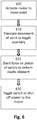
- FIG. 6 is a flowchart of a method of operating a point machine with the electrical switch according to an exemplary embodiment of the invention.
- the switch described in this method is substantially similar to the embodiments of electrical switch 100 and its corresponding components/elements, described above.
- step 600 the motor of the point machine is activated to move the point from a first position to a second position.
- step 610 the movement of the point is translated to a toggle assembly, preferably via one or more rods, as described in the above embodiments.
- step 600 and 610 occur substantially simultaneously.
- the toggle assembly exerts a force on a piston of the electrical switch to deform an elastic element within the switch.
- the switch is kept in the toggled closed position by one or more magnets to supply power to the motor.
- Deformation of the elastic element stores energy in the elastic element.
- step 630 when the elastic element is deformed a predetermined amount, the force of the stored energy exceeds the magnetic force keeping the switch closed and the electrical switch is toggled open, shutting off power to the motor.
- the movement of the toggle assembly, force of the magnet, and the deformation of the elastic element are selected/calibrated such that the electrical switch is toggled open, turning off the motor, when the point completes its movement from the first position to the second.
Landscapes
- Engineering & Computer Science (AREA)
- Mechanical Engineering (AREA)
- Mechanisms For Operating Contacts (AREA)
- Connection Of Motors, Electrical Generators, Mechanical Devices, And The Like (AREA)
Description
- Aspects of the present invention generally relate to an electrical switch with snap-action for a point machine, a point machine with said electrical switch, and method of operating said point machine.
- In general, a railroad point (also referred to a turnout) is a mechanical installation at a section of railroad track where the track diverges into two separate tracks: a straight track and a diverging track. The point consists of a set of blades that move laterally between two positions to direct an oncoming train onto either the either the straight or diverging track (for ease of reference, the set of blades will be referred to simply as the "point" hereafter). The operation of a point is well known to one of skill in the art and will not be discussed in greater detail.
- The movement of the points is operated by a railroad track point machine (also known as a point motor, switch machine or switch motor). In the past, point machines were purely mechanical, employing hand-thrown levers or rod/wires to operate the point machine at a distance. Over the years, improvements in rail infrastructure have necessitated more powerful point machines driven hydraulically or electrically. Modern point machines employ at least one electrical motor to move the point between its two positions. The operation of a point machine is well known to one of skill in the art and will not be discussed in greater detail.
- Safety is the most important design criteria for point machines. When moving track to divert a fast moving train, the tolerance for error is extremely low and the results of a malfunction can be catastrophic. It is crucial that the point machine executes the movement of the point precisely and reliably. The motor most move the point an exact distance in a desired direction and shut off at the end of travel. It is important to verify that the motor has shut off.
- The patent publication
WO 01/15955 - Operation of the motor is controlled by an electrical switch (not to be confused with a railroad switch, which is another term used to describe a point or turnout). Mechanical force (usually from movement generated by the motor) opens the electrical switch, cutting off power to the motor, once the motor has completed movement of the point from a first position to the second position. There are a variety of switches that have been employed for this purpose. However, current switch designs are complex and prone to failure through contamination, wear from mechanical stress and vibrational forces.
- A significant design need exists for a switch design with the following properties: snap-action to reduce arcing between contacts; detectable switch toggle position, positive override to ensure contact break; and contact wiping ability. It is desirable for these features to fit into the footprint of current switch designs, alleviating the need to alter the internal arrangement of the point machine. The present invention meets all of these functional and design criteria.
- The present invention is directed to an electric switch for a point machine, a point machine with said electrical switch, and a method of operating said point machine. In accordance with one aspect of the invention, the present invention is an electrical switch according to
claim 1 with an elastic element, preferably integral to the switch, disposed within the housing for toggling the switch open and closed to regulate current flow to the motor of a point machine. - In accordance with another aspect of the invention, the invention is a point machine according to claim 8 with such an electrical switch having a deformable elastic element. The point machine comprises a toggle assembly that can translate movement of the point induced by the motor to the electrical switch. Specifically, the toggle assembly acts upon the switch to deform the elastic element and cause the switch to "snap" open, to reducing the likelihood of arcing when the circuit opens.
- In accordance with another aspect of the invention, the invention is a method of operating a point machine according to claim 9. The method comprises activating a motor to move a point, the movement of the point translated to an electrical switch by a toggle assembly. The toggle assembly acting on the electrical switch to deform an elastic element within the electrical switch, causing the electrical switch to snap open and cut off power to the motor substantially simultaneously to the point completing its movement.
-
-
FIG. 1 illustrates an exemplary embodiment of the switch in the closed position. -
FIG. 2 illustrates an exemplary embodiment of the switch in the closed position with the piston partially depressed. -
FIG. 3 illustrates an exemplary embodiment of the switch in the open position. -
FIG. 4A illustrates a point machine with a toggle assembly and switches according to the prior art. -
FIG. 4B illustrates a close-up of the toggle assemble and a switch according to the prior art. -
FIG. 5 illustrates an exemplary embodiment of the toggle assembly and switch in a point machine. -
FIG. 6 illustrates a flowchart of a method of operating a point machine. - To facilitate an understanding of embodiments, principles, and features of the present invention, they are explained hereinafter with reference to implementation in illustrative embodiments.
- The components and materials described hereinafter as making up the various embodiments are intended to be illustrative and not restrictive. Many suitable components and materials that would perform the same or a similar function as the materials described herein are intended to be embraced within the scope of embodiments of the present invention.
-
FIG. 1 illustrates an exemplary embodiment of theelectrical switch 100 in the closed position. Theswitch 100 comprises ahousing 110, which preferably has a design footprint similar to existing switches and can be retrofit or incorporated into new units without significant design change to the point machine. Theelectrical switch 100 is preferably disposed inside of the point machine (not pictured), but in other embodiments may be installed outside the main point machine housing. - In accordance with a preferred embodiment, the
housing 110 has two sets of fixed contacts.Motor contacts electrical switch 100 is in the closed position (described in more detail below) current flows betweenmotor contacts Detection contacts electrical switch 100 is toggled closed and the motor is powered or theelectrical switch 100 is toggled open, as described in more detail inFig. 3 below. - In accordance with preferred embodiment, the
electrical switch 100 further comprises a movingcontact assembly 140, preferably disposed within thehousing 110. Theassembly 140 comprises a pair ofmirroring contact frames frames leaf springs contacts 143a and b and 144a and b disposed at their distal ends, respectively. In accordance with an exemplary embodiment, themoving contacts 143a and b and 144a and b are made of beryllium cooper. Additionally, in accordance with an exemplary embodiment, themoving contacts 143a and b and 144a and b all have rounded "wiping" surfaces. As themoving contacts 143a and b and 144a and b come into contact withfixed contacts 120a and b and 130a and b, respectively,springs 142a and b are deformed/bent allowing the surfaces of movingcontacts 143a and b and 144a and b to pivot against the surface offixed contacts 120a and b and 130a and b, this movement effectively cleaning or "wiping" residue or contaminants off the surface that could impede current flow. - In accordance with a preferred embodiment, the moving
contact assembly 140 is mounted oncylinder 150. Thecylinder 150 is mounted within thehousing 110 such that thecylinder 150 can axially, bi-directionally translate a predetermined travel distance. Axial movement of thecylinder 150 carries the movingcontact assembly 140 back and forth between the fixedcontacts 120a and b and 130a and b, opening and closing the circuits as it moves, thereby toggling theelectrical switch 100. Apiston 151 is also provided, partially mounted within thehousing 110 and partially extending outside thehousing 110. In accordance with an embodiment of the invention, thepiston 151 is coaxially mounted relative to thecylinder 150. In a preferred embodiment, a portion of thepiston 151 is disposed within thecylinder 150, allowing thepiston 151 to slide axially relative thecylinder 150. In an alternative embodiment, thecylinder 150 could be disposed partially within thepiston 151. Other mounting arrangements allowing thecylinder 150 andpiston 151 to move relative to each other are also contemplated. Aspring 152 can be mounted such that movement of thepiston 151 relative to thecylinder 150 causes to thespring 152 to deform. Thespring 152 is illustrated as a conventional coil spring. However, it is contemplated that a different type spring or other elastic element having appropriate elasticity could be used. The terms elastic element and spring may be used interchangeably within this specification, but term elastic element contemplates a broader range of elements capable of being deformed. A spring is just a preferred embodiment of an elastic element. - In accordance with a preferred embodiment, a pair of
magnets 160a and b are mounted within thehousing 110. Themagnets 160a and b are preferably permanent magnets, but electromagnets are contemplated as well. In alternative embodiments, a single magnet or multiple magnets could be used in place of the twomagnets 160a and b depicted in this embodiment. Aferrous plate 170 is located on the end of thecylinder 150 opposite thepiston 151. Themagnets 160a and b exert an attractive magnetic force on theferrous plate 170. When theplate 170 is "fixed" to themagnets 160a and b, thecylinder 150 is locked in a fixed position and unable to move within thehousing 110 until the connection between theplate 170 andmagnets 160 a and b is broken. -
Fig. 1 depicts theswitch 100 toggled in closed position. Thiselectrical switch 100 is referred to as being toggled closed because the circuit including the motor and power supply is closed because current can flow between motor contacts 102a and b through movingcontacts 143a and b andleaf spring 142a. Theelectrical switch 100 is kept locked in the closed position by the magnetic force ofmagnets 160a and b exerted onplate 170, which keeps thecylinder 150 in a fixed position such that theassembly 140 is proximate themotor contacts 120a and b andleaf spring 142a is depressed and movingcontacts 143a and b are in physical contact with themotor contacts 120a and b, respectively, allowing current to flow between saidcontacts 120a and b through the movingcontacts 143a and b andspring 142a. When theelectrical switch 100 is toggled in the closed position, the motor is able to operate and move the point from a first position to a second.Figs. 2 and3 illustrate the movement of theelectrical switch 100 elements and operation/toggling of theelectrical switch 100. - All of the elements in
Fig. 2 are identical toFig. 1 .Fig. 2 illustrates theelectrical switch 100 still toggled in the closed position, but thepiston 151 being translated axially in the direction of thecylinder 150. Movement of thepiston 151 is induced by the toggle assembly (not pictured), which is in communication with the motor, as will be discussed in more detail below. The motor moves the point, which move one or more rods, which are connected to a toggle assembly, which toggles the electrical switch by exerting a force on thepiston 151, moving it toward thecylinder 150, compressing thespring 152 because thecylinder 150 remains held fixed in place by the force exerted by themagnets 160a and b on theplate 170. As long as the magnetic force between themagnets 160a and b andplate 170 is greater than the mechanical force stored in thespring 152, theelectrical switch 100 will remain closed and the motor will keep moving the points and further compressing thespring 152. The mechanical force will continue to grow in thespring 152 in accordance with Hooke's Law. In a preferred embodiment of the invention, the spring constant is selected such that the mechanical force in thespring 152 exceeds the magnetic force between themagnets 160a and b andplate 170 when the motor has fully moved the point from the first position to the second position. When this occurs the stored mechanical energy in thespring 152 is released and "snaps" thecylinder 150 axially in a direction away from thepiston 151, thereby opening theelectrical switch 100 and cutting off current flow to the motor. It is desired to shut the motor off at this time since the motor has completed moving the point. The "snap-action" caused by thespring 152 reduces potential for arcing between the movingcontacts 143a and b andmotor contacts 120a and b. - The
electrical switch 100 includes an integral "fail safe" if the "snap-action" should fail. The most likely point of failure is thespring 152 that generates the "snap-action". If thespring 152 breaks or malfunctions, thepiston 151 will continue to toward thecylinder 150. The range of movement of thepiston 151 relative to thecylinder 150, however, is limited so that thepiston 151 moves relative to the cylinder 150 a predetermined amount after which it pushes thecylinder 150. The range of movement of thepiston 151 relative to thecylinder 150 is less than the distance of the movement of thecylinder 150 from the first position to the second position. The range is set so that thepiston 151 would push thecylinder 150, overcoming the force of themagnets 160a and b, opening theelectrical switch 100 and shutting off the motor, at the same time as the motor completes movement of the point, thus shutting off the motor. - All of the elements in
FIG. 3 are identical toFIGS. 1 and2 . InFIG. 3 , theelectrical switch 100 has been toggled/"snapped" open due to the movement generated by themotor compressing spring 152 until the stored mechanical energy exceeded the magnetic force betweenplate 170 andmagnets 160a and b. Thespring 152 "snapping" thecylinder 150 in a direction away from thepiston 151 also moves theentire assembly 140 away from themotor contacts 120a and b, preventing current flow between thecontacts 120a and b, opening the circuit with the motor and power supply, shutting off power to the motor and preventing further movement of the point by the motor. The "snap-action" reduces the potential for harmful electric arcing between the contacts. In the open position, the movingcontacts 144a and b are pressed againstdetection contacts 130a and b, closing the detection circuit and allowing current to flow betweencontacts 130a and b through movingcontacts 144a and b andleaf spring 142b. The detection circuit is used to confirm that theelectrical switch 100 is operating properly, toggled open, and power to the motor has been shut off. If the detection circuit is closed, the motor circuit must be open. -
FIG. 4A illustrates a point machine with a toggle assembly and switches according to the prior art. Apoint machine 400 comprises amotor housing 401. At least one motor (not pictured) for moving the point is disposed within themotor housing 401. Apoint machine 400 also comprises atoggle assembly housing 405, within which thetoggle assembly 420 is housed. Thetoggle assembly 420 can comprise an arrangement of hinged levers that translate movement of the point, induced by the motor of the point machine, via one ormore rods 425, to switches 410. Specifically, the motor moves the point, which is connected to and causes movement of therods 425, which move the levers of thetoggle assembly 420; movement of the levers activates/toggles theswitches 410, controlling current flow to the motor. Therods 425 and toggleassembly 420 are calibrated such that the appropriateelectrical switch 100 is toggled open to shut off the motor when it completes movement of the point.Switches 410 perform similar basic functions aselectrical switch 100 described above in regulating current flow to the motor, but lack the features ofelectrical switch 100. Among the distinctions betweenswitches 410 andelectrical switch 100 is the integral "snap-action" ofelectrical switch 100 described above. In contrast, the "snap-action" in the prior art is achieved by a spring mechanism in theassembly 420, not in theswitch 410 itself. -
FIG. 4B illustrates a close-up of thetoggle assembly 420 and aswitch 410 according to the prior art. Thetoggle assembly 420 comprises an arrangement of hinged levers that translate movement of the point induced by the motor to theswitch 410 as described above. Thetoggle assembly 420 comprises anintermediary lever 421 that acts upon atoggle lever 422. Thetoggle lever 422 toggles theswitch 410 by pressing against and moving thepiston 451.Piston 451 performs a similar function topiston 151. As discussed previously, theswitch 410 does not have integral "snap-action" asswitch 100 does. Instead, the necessary "snap" to avoid arcing in the contacts is achieved in the prior art by disposing anelastic toggle element 430 betweenintermediary lever 421 andtoggle lever 422. Movement of theintermediary lever 421 deforms theelastic toggle element 430, rather than directly moving thetoggle lever 422. When theelastic toggle element 430 has been deformed a predetermined amount, then energy stored within it is released causing thetoggle lever 422 to "snap" andpush piston 451 to toggleswitch 451 into the open position, shutting off power to the motor. This is a more complicated and less reliable arrangement than the operation of theelectrical switch 100 described above. It is known to one of ordinary skill in the art that the toggle assembly can operate a plurality ofswitches 410 and has a mirror arrangement as pictured, although only on "side" is discussed in detail above. -
FIG. 5 illustrates close-up of thetoggle assembly 520 andelectrical switch 100 according to a preferred embodiment of the invention.FIG. 5 does not show the entire point machine, the housing, motor, and other not pictured components being substantially similar to those illustrated inFIG. 4A .Electrical switch 100 is the same as described above inFIGS. 1-3 . Thetoggle assembly 520 is disposed withinhousing 505. Translation of the movement of the point by the motor throughrods 525 to theassembly 520 is substantially similar as described above in relation toFIG. 4A . However, the engagement of theelectrical switch 100 by theassembly 520 differs from the prior art, because of the "snap-action" integral toelectrical switch 100. -
Toggle assembly 520 translates movement induced by the motor fromrods 525 through theassembly 520 to thepiston 151 to toggleelectrical switch 100. Specifically,intermediary lever 523 exerts a force directly ontoggle lever 522, which presses againstpiston 151, toggling the switch between first and second (open and closed) positions as described above. It is important to note that no elastic element is interposed between theintermediary lever 523 andtoggle lever 522, unlike assemble 420 that utilizeselement 430. This is because the point machine of this exemplary embodiment of the invention comprises theelectrical switch 100 having integral "snap-action", as described above, which simplifies the design of thetoggle assembly 520 by removing the need for an elastic element that can generate "snap" toggling. - A comparison of
toggle assembly assembly 520 does not have components equivalent to togglelever 422 andelastic toggle element 430, these components being unnecessary since "snap-action" is generated integrally withinelectrical switch 100. Instead, togglelever 522 directly interfaces withpiston 151 to toggleelectrical switch 100, as described above.Toggle assembly 520 is simpler and more reliable thantoggle assembly 420 because the design does not require components to generate "snap-action", which require maintenance and are prone to failure. -
FIG. 6 is a flowchart of a method of operating a point machine with the electrical switch according to an exemplary embodiment of the invention. The switch described in this method is substantially similar to the embodiments ofelectrical switch 100 and its corresponding components/elements, described above. Instep 600, the motor of the point machine is activated to move the point from a first position to a second position. Instep 610, the movement of the point is translated to a toggle assembly, preferably via one or more rods, as described in the above embodiments. Preferably,step step 620, the toggle assembly exerts a force on a piston of the electrical switch to deform an elastic element within the switch. The switch is kept in the toggled closed position by one or more magnets to supply power to the motor. Deformation of the elastic element stores energy in the elastic element. Instep 630, when the elastic element is deformed a predetermined amount, the force of the stored energy exceeds the magnetic force keeping the switch closed and the electrical switch is toggled open, shutting off power to the motor. The movement of the toggle assembly, force of the magnet, and the deformation of the elastic element are selected/calibrated such that the electrical switch is toggled open, turning off the motor, when the point completes its movement from the first position to the second. - In the foregoing specification, the invention has been described with reference to specific embodiments. However, one of ordinary skill in the art appreciates that various modifications and changes can be made without departing from the scope of the invention as claimed. Accordingly, the specification and figures are to be regarded in an illustrative rather than a restrictive sense, and all such modifications are intended to be included within the scope of invention.
- Although the invention has been described with respect to specific embodiments thereof, these embodiments are merely illustrative, and not restrictive of the invention. The description herein of illustrated embodiments of the invention is not intended to be exhaustive or to limit the invention to the precise forms disclosed herein (and in particular, the inclusion of any particular embodiment, feature or function is not intended to limit the scope of the invention to such embodiment, feature or function). Rather, the description is intended to describe illustrative embodiments, features and functions in order to provide a person of ordinary skill in the art context to understand the invention without limiting the invention to any particularly described embodiment, feature or function. While specific embodiments of, and examples for, the invention are described herein for illustrative purposes only, various equivalent modifications are possible within the scope of the invention within the scope of the claims, as those skilled in the relevant art will recognize and appreciate. As indicated, these modifications may be made to the invention in light of the foregoing description of illustrated embodiments of the invention and are to be included within the scope of the invention. Thus, while the invention has been described herein with reference to particular embodiments thereof, a latitude of modification, various changes and substitutions are intended in the foregoing disclosures, and it will be appreciated that in some instances some features of embodiments of the invention will be employed without a corresponding use of other features without departing from the scope of the invention as claimed.
- Therefore, many modifications may be made to adapt a particular situation or material to the essential scope of the invention.
Claims (12)
- An electrical switch (100) for a point machine, the electrical switch (100) comprising:a housing (110);a first motor contact (120a) and a second motor contact (120b) disposed within the housing (110), the motor contacts (120a, 120b) in electrical communication with a motor circuit providing power to an electrical motor of the point machine;a cylinder (150) disposed within the housing (110) such that the cylinder (150) can move within the housing (110) between a first position and a second position;a first contact frame (141a) attached to the cylinder (150), the contact frame (141a) moving with the cylinder (150);a first moving contact (143a) and a second moving contact (143b) disposed on the first contact frame (141a) and moving with the cylinder (150, the first contact frame (141a) and first and second moving contacts (143a, 143b) providing electrical communication between the first and second motor contacts (120a, 120b) when the cylinder (150) is in the first position;a piston (151) partially disposed outside the housing (110), the piston (151) in communication with the cylinder (150), the piston (151) capable of moving within the housing (110) relative to the cylinder 150);an elastic element in communication with the cylinder (150) and the piston (151),wherein movement of the piston (151) relative to the cylinder (150) deforms the elastic element;a magnetic element (160a, 160b) attached to the housing (110) being adapted to exert a magnetic force on the cylinder (150) keeping the cylinder (150) stationary in the first position from moving relative to the housing (110);wherein the electrical switch (100) is configured such that a movement of the piston (151) relative to the cylinder (150) exerts a first force on the elastic element deforming the elastic element, the deformation of the elastic element causing the elastic element to exert a second force on the cylinder (150), the cylinder (150) being able to move from the first position to the second position when the second force exceeds the magnetic force.
- The electrical switch of claim 1, wherein when cylinder (150) is in the first position the motor circuit is closed and current can flow to the electrical motor, or wherein when the cylinder is in the second position the motor circuit is open and current cannot flow to the electrical motor.
- The electrical switch of claim 1, the first and second moving contacts (143a, 143b) attached to the first contact frame (141a) by a leaf spring (142a), the spring (142a) being deformed and pushing the first and second moving contacts (143a, 143b) against the surface of the motor contacts (120a, 120b) when the cylinder is in the first position.
- The electrical switch of claim 3, the first and second moving contacts (143a, 143b) having a rounded surface, wherein the surfaces of the first and second moving contacts (143a, 143b) pivot against the surface of the motor contacts as the cylinder (150) moves to or from the first position, thereby wiping contaminants off the surface of the first and second moving contacts (143a, 143b) and the surface of the motor contacts.
- The electrical switch of claim 1, the distance the piston (151) can move relative to the cylinder (150) being less than the distance the cylinder (150) moves between the first position and second position.
- The electrical switch of claim 1, the longitudinal axes of the cylinder (150) and piston (151) being collinear, the cylinder (150) and piston (151) moving within the housing parallel to the longitudinal axes.
- The electrical switch of claim 1, further comprising:
a first detection contact (130a) and a second detection contact (130b) disposed within the housing (110), the detection contacts (130a, 130b) in electrical communication with a detection circuit;
a second contact frame (141b) attached to the cylinder (150), the second contact frame (141b) moving with the cylinder (150);
a third moving contact (144a) and a fourth moving (144b) contact disposed on the second contact frame (141b) and moving with the cylinder (150), the second contact frame (141b) and third and fourth moving contacts (144a, 144b) providing electrical communication between the first and second detection contacts (130a, 130b) when the piston (151) is in the second position, thereby closing a detection circuit, the closed detection circuit being indicative of the motor circuit being open. - A point machine having the electrical switch of claim 1, the point machine comprising:a motor in communication with a point;a toggle assembly (520) in mechanical communication with the point, wherein movement of the point induced by the motor is translated to movement of the toggle assembly (520), the toggle assembly (520) exerting a force on the piston (151) of the electrical switch (100).
- A method for operating a point machine with the electrical switch (100) according to claim 1 comprising a housing (110), a cylinder (150) and a piston (151); the method comprising:Activating (600) a motor of the point machine to move a point from a first position to a second position;Translating (610) the movement of the point to movement of a toggle assembly (520) of the point machine;Exerting (620) a force by the movement of the toggle assembly (520) on the piston (151) to deform an elastic element within the electrical switch (100);Toggling (630) the electrical switch (100) open to shut off power to the motor when the elastic element is deformed a predetermined amount;Keeping the electrical switch (100) closed in the first position by a magnetic element (160a, 160b) within the switch (100);the magnetic element (160a, 160b) attached to the housing (110) exerting a magnetic force on the cylinder (150) keeping the cylinder (150) stationary in the first position from moving relative to the housing (110); wherein movement of the piston (151) relative to the cylinder (150) exerts a first force on the elastic element deforming the elastic element, the deformation of the elastic element causing the elastic element to exert a second force on the cylinder (150), the cylinder (150) being able to move from the first position to the second position when the second force exceeds the magnetic force.
- The method of claim 9, wherein the elastic element is deformed a predetermined amount when the point completes its movement from the first position to the second position.
- The method of claim 9, wherein the step of toggling the electrical switch (100) open comprises the force stored in the elastic element due to its deformation exceeding the force exerted by the magnetic element (160a, 160b).
- The method of claim 9, wherein the point machine is a point machine according to claim 8.
Priority Applications (1)
| Application Number | Priority Date | Filing Date | Title |
|---|---|---|---|
| PL15813171T PL3380386T3 (en) | 2015-11-24 | 2015-11-24 | Point machine and electrical switch with snap-action and method of operating said point machine |
Applications Claiming Priority (1)
| Application Number | Priority Date | Filing Date | Title |
|---|---|---|---|
| PCT/US2015/062248 WO2017091202A1 (en) | 2015-11-24 | 2015-11-24 | Point machine and switch with snap-action and method of operating said point machine |
Publications (2)
| Publication Number | Publication Date |
|---|---|
| EP3380386A1 EP3380386A1 (en) | 2018-10-03 |
| EP3380386B1 true EP3380386B1 (en) | 2021-03-17 |
Family
ID=54884385
Family Applications (1)
| Application Number | Title | Priority Date | Filing Date |
|---|---|---|---|
| EP15813171.4A Active EP3380386B1 (en) | 2015-11-24 | 2015-11-24 | Point machine and electrical switch with snap-action and method of operating said point machine |
Country Status (8)
| Country | Link |
|---|---|
| US (1) | US10850752B2 (en) |
| EP (1) | EP3380386B1 (en) |
| CN (1) | CN109415072B (en) |
| AU (1) | AU2015415489B2 (en) |
| DK (1) | DK3380386T3 (en) |
| ES (1) | ES2864703T3 (en) |
| PL (1) | PL3380386T3 (en) |
| WO (1) | WO2017091202A1 (en) |
Families Citing this family (3)
| Publication number | Priority date | Publication date | Assignee | Title |
|---|---|---|---|---|
| PL3380386T3 (en) * | 2015-11-24 | 2021-09-20 | Siemens Mobility Pty Ltd. | Point machine and electrical switch with snap-action and method of operating said point machine |
| CN116373941B (en) * | 2023-04-14 | 2025-10-10 | 太原国铁京丰装备技术股份有限公司 | A switch machine and its action plate assembly mechanism |
| WO2024226051A1 (en) * | 2023-04-27 | 2024-10-31 | Advanced Rail Systems, Llc | Railroad switch device |
Family Cites Families (24)
| Publication number | Priority date | Publication date | Assignee | Title |
|---|---|---|---|---|
| AT405925B (en) * | 1997-05-27 | 1999-12-27 | Vae Ag | DEVICE FOR LOCKING THE END OF MOVING PARTS |
| US6427950B1 (en) * | 1999-06-04 | 2002-08-06 | Meridian Rail Information Systems Corp. | Electrically operated railroad switch machine |
| ATA149899A (en) | 1999-08-31 | 2005-10-15 | Vae Ag | DEVICE FOR DETERMINING THE LOCKING POSITION OR MOVEMENT POSITION OF A CYLINDER PISTON UNIT OF A SOFT DRIVE |
| AT411047B (en) * | 2001-01-11 | 2003-09-25 | Vae Eisenbahnsysteme Gmbh | DEVICE FOR LOCKING THE END OF MOVING PARTS |
| AT5706U1 (en) * | 2001-05-07 | 2002-10-25 | Vae Eisenbahnsysteme Gmbh | METHOD FOR INSTALLING SOURCES IN TRACKS AND SOFTWARE FOR IMPLEMENTING THIS METHOD |
| AT5757U1 (en) * | 2001-07-31 | 2002-11-25 | Vae Eisenbahnsysteme Gmbh | DEVICE FOR MOVING SWITCHES |
| AT411241B (en) * | 2001-08-02 | 2003-11-25 | Vae Eisenbahnsysteme Gmbh | DEVICE FOR LOCKING THE END OF MOVING PARTS |
| AT6379U3 (en) * | 2003-05-09 | 2005-06-27 | Vae Eisenbahnsysteme Gmbh | DEVICE FOR REMOTELY MONITORING SOFT DRIVES |
| US9156479B2 (en) * | 2004-01-02 | 2015-10-13 | Donald Coy Beamon | Hydraulic switch machine for railroads |
| CN1944145A (en) * | 2006-10-14 | 2007-04-11 | 史长春 | Rail switching device for electric control switch |
| US7753318B2 (en) * | 2007-01-31 | 2010-07-13 | General Electric Company | System and method for temporary protection operation of a controller box for a railroad switch turnout |
| US7699272B2 (en) * | 2007-09-14 | 2010-04-20 | Jim Arnold | Railroad switching indicator mechanism |
| CN201544999U (en) * | 2009-10-22 | 2010-08-11 | 史长春 | Actuating device of electric driver-controlling turnout rail switch machine |
| CN101734263B (en) * | 2009-12-24 | 2013-03-20 | 徐州中矿大矿山设备有限公司 | Electric linear points switch machine |
| US8684318B2 (en) * | 2010-09-16 | 2014-04-01 | Spx International Limited | Mechanical lock |
| CN202279135U (en) | 2011-09-22 | 2012-06-20 | 无锡市锡湖液压气动机械有限公司 | Pneumatic turnout switch machine |
| US20130264431A1 (en) * | 2012-04-05 | 2013-10-10 | Daniel H. Brushwood | Rail mount point detector for railroad switches |
| WO2015013492A1 (en) * | 2013-07-24 | 2015-01-29 | Ansaldo Sts Usa, Inc. | Point detection calibration before switch machine failure |
| CN104512436B (en) | 2013-09-30 | 2017-04-19 | 西门子信号有限公司 | Point switch machine |
| US9863096B2 (en) * | 2015-07-02 | 2018-01-09 | James Arnold | Point detector overtie structure |
| PL3380386T3 (en) * | 2015-11-24 | 2021-09-20 | Siemens Mobility Pty Ltd. | Point machine and electrical switch with snap-action and method of operating said point machine |
| US10953897B2 (en) * | 2016-09-30 | 2021-03-23 | Hitachi Rail Sts Usa, Inc. | Electronic circuit controller for railway switch machine, railway switch machine and railway switching system including same |
| EP3412535B1 (en) * | 2017-06-08 | 2019-12-11 | ALSTOM Transport Technologies | Switching machine for a railroad |
| US10710617B2 (en) * | 2017-08-24 | 2020-07-14 | Alstom Transport Technologies | Control and monitoring device for a switch machine, a system and method for monitoring a switch machine |
-
2015
- 2015-11-24 PL PL15813171T patent/PL3380386T3/en unknown
- 2015-11-24 CN CN201580085735.1A patent/CN109415072B/en active Active
- 2015-11-24 ES ES15813171T patent/ES2864703T3/en active Active
- 2015-11-24 WO PCT/US2015/062248 patent/WO2017091202A1/en not_active Ceased
- 2015-11-24 US US15/778,695 patent/US10850752B2/en active Active
- 2015-11-24 DK DK15813171.4T patent/DK3380386T3/en active
- 2015-11-24 AU AU2015415489A patent/AU2015415489B2/en active Active
- 2015-11-24 EP EP15813171.4A patent/EP3380386B1/en active Active
Non-Patent Citations (1)
| Title |
|---|
| None * |
Also Published As
| Publication number | Publication date |
|---|---|
| ES2864703T3 (en) | 2021-10-14 |
| WO2017091202A1 (en) | 2017-06-01 |
| EP3380386A1 (en) | 2018-10-03 |
| US20180346002A1 (en) | 2018-12-06 |
| DK3380386T3 (en) | 2021-05-10 |
| CN109415072A (en) | 2019-03-01 |
| AU2015415489B2 (en) | 2019-06-20 |
| US10850752B2 (en) | 2020-12-01 |
| PL3380386T3 (en) | 2021-09-20 |
| AU2015415489A1 (en) | 2018-06-21 |
| CN109415072B (en) | 2021-09-07 |
Similar Documents
| Publication | Publication Date | Title |
|---|---|---|
| EP2782110B1 (en) | Lorentz force activated electric switching device | |
| JP6275884B2 (en) | New magnetic proximity switch | |
| KR101448136B1 (en) | Devise operating for vacuum circuitbreaker | |
| CN104347324B (en) | Breaker | |
| AU2015415489B2 (en) | Point machine and switch with snap-action and method of operating said point machine | |
| US9530578B2 (en) | Electrical switching apparatus and transmission assembly therefor | |
| US7834280B2 (en) | Safety switch | |
| RU2470400C1 (en) | Emergency disconnection device | |
| RU2011143743A (en) | DISCONNECTOR FOR ELECTRICAL SWITCHING DEVICE | |
| TWI382435B (en) | Microswitch | |
| KR102518006B1 (en) | medium voltage switching device | |
| US8785797B2 (en) | Medium voltage circuit breaker | |
| KR20150134388A (en) | Drive for a switching device | |
| WO2019044071A1 (en) | Vacuum switch device and anomaly monitoring method therefor | |
| CN206758313U (en) | Dual-power transfer switch | |
| US7800004B2 (en) | Safety switch | |
| CA2563695C (en) | Fault interrupter and disconnect device | |
| DE69834153D1 (en) | Electrical arrangement with actuator for a load switch, with malfunction indicator | |
| KR102067270B1 (en) | Fast switch | |
| CN113826177A (en) | Switchgear with self-cleaning contacts | |
| SU1624555A1 (en) | Current-limiting switching device | |
| RU2367049C1 (en) | Vacuum contactor | |
| EP2907148B1 (en) | Actuator for low-, medium- or high-voltage switchgears | |
| KR200454683Y1 (en) | Vacuum circuit breaker | |
| HRP20250264T1 (en) | ALTERNATING ELECTRICAL SWITCH |
Legal Events
| Date | Code | Title | Description |
|---|---|---|---|
| STAA | Information on the status of an ep patent application or granted ep patent |
Free format text: STATUS: THE INTERNATIONAL PUBLICATION HAS BEEN MADE |
|
| PUAI | Public reference made under article 153(3) epc to a published international application that has entered the european phase |
Free format text: ORIGINAL CODE: 0009012 |
|
| STAA | Information on the status of an ep patent application or granted ep patent |
Free format text: STATUS: REQUEST FOR EXAMINATION WAS MADE |
|
| 17P | Request for examination filed |
Effective date: 20180524 |
|
| AK | Designated contracting states |
Kind code of ref document: A1 Designated state(s): AL AT BE BG CH CY CZ DE DK EE ES FI FR GB GR HR HU IE IS IT LI LT LU LV MC MK MT NL NO PL PT RO RS SE SI SK SM TR |
|
| AX | Request for extension of the european patent |
Extension state: BA ME |
|
| DAV | Request for validation of the european patent (deleted) | ||
| DAX | Request for extension of the european patent (deleted) | ||
| STAA | Information on the status of an ep patent application or granted ep patent |
Free format text: STATUS: EXAMINATION IS IN PROGRESS |
|
| 17Q | First examination report despatched |
Effective date: 20190621 |
|
| RAP1 | Party data changed (applicant data changed or rights of an application transferred) |
Owner name: SIEMENS MOBILITY PTY LTD. |
|
| GRAP | Despatch of communication of intention to grant a patent |
Free format text: ORIGINAL CODE: EPIDOSNIGR1 |
|
| STAA | Information on the status of an ep patent application or granted ep patent |
Free format text: STATUS: GRANT OF PATENT IS INTENDED |
|
| INTG | Intention to grant announced |
Effective date: 20201124 |
|
| GRAS | Grant fee paid |
Free format text: ORIGINAL CODE: EPIDOSNIGR3 |
|
| GRAA | (expected) grant |
Free format text: ORIGINAL CODE: 0009210 |
|
| STAA | Information on the status of an ep patent application or granted ep patent |
Free format text: STATUS: THE PATENT HAS BEEN GRANTED |
|
| AK | Designated contracting states |
Kind code of ref document: B1 Designated state(s): AL AT BE BG CH CY CZ DE DK EE ES FI FR GB GR HR HU IE IS IT LI LT LU LV MC MK MT NL NO PL PT RO RS SE SI SK SM TR |
|
| REG | Reference to a national code |
Ref country code: GB Ref legal event code: FG4D |
|
| REG | Reference to a national code |
Ref country code: CH Ref legal event code: EP |
|
| REG | Reference to a national code |
Ref country code: DE Ref legal event code: R096 Ref document number: 602015067045 Country of ref document: DE |
|
| REG | Reference to a national code |
Ref country code: IE Ref legal event code: FG4D |
|
| REG | Reference to a national code |
Ref country code: AT Ref legal event code: REF Ref document number: 1371988 Country of ref document: AT Kind code of ref document: T Effective date: 20210415 |
|
| REG | Reference to a national code |
Ref country code: DK Ref legal event code: T3 Effective date: 20210504 |
|
| REG | Reference to a national code |
Ref country code: FI Ref legal event code: FGE |
|
| REG | Reference to a national code |
Ref country code: LT Ref legal event code: MG9D |
|
| PG25 | Lapsed in a contracting state [announced via postgrant information from national office to epo] |
Ref country code: NO Free format text: LAPSE BECAUSE OF FAILURE TO SUBMIT A TRANSLATION OF THE DESCRIPTION OR TO PAY THE FEE WITHIN THE PRESCRIBED TIME-LIMIT Effective date: 20210617 Ref country code: GR Free format text: LAPSE BECAUSE OF FAILURE TO SUBMIT A TRANSLATION OF THE DESCRIPTION OR TO PAY THE FEE WITHIN THE PRESCRIBED TIME-LIMIT Effective date: 20210618 Ref country code: HR Free format text: LAPSE BECAUSE OF FAILURE TO SUBMIT A TRANSLATION OF THE DESCRIPTION OR TO PAY THE FEE WITHIN THE PRESCRIBED TIME-LIMIT Effective date: 20210317 Ref country code: BG Free format text: LAPSE BECAUSE OF FAILURE TO SUBMIT A TRANSLATION OF THE DESCRIPTION OR TO PAY THE FEE WITHIN THE PRESCRIBED TIME-LIMIT Effective date: 20210617 |
|
| REG | Reference to a national code |
Ref country code: NL Ref legal event code: MP Effective date: 20210317 |
|
| PG25 | Lapsed in a contracting state [announced via postgrant information from national office to epo] |
Ref country code: RS Free format text: LAPSE BECAUSE OF FAILURE TO SUBMIT A TRANSLATION OF THE DESCRIPTION OR TO PAY THE FEE WITHIN THE PRESCRIBED TIME-LIMIT Effective date: 20210317 Ref country code: LV Free format text: LAPSE BECAUSE OF FAILURE TO SUBMIT A TRANSLATION OF THE DESCRIPTION OR TO PAY THE FEE WITHIN THE PRESCRIBED TIME-LIMIT Effective date: 20210317 Ref country code: SE Free format text: LAPSE BECAUSE OF FAILURE TO SUBMIT A TRANSLATION OF THE DESCRIPTION OR TO PAY THE FEE WITHIN THE PRESCRIBED TIME-LIMIT Effective date: 20210317 |
|
| PG25 | Lapsed in a contracting state [announced via postgrant information from national office to epo] |
Ref country code: NL Free format text: LAPSE BECAUSE OF FAILURE TO SUBMIT A TRANSLATION OF THE DESCRIPTION OR TO PAY THE FEE WITHIN THE PRESCRIBED TIME-LIMIT Effective date: 20210317 |
|
| REG | Reference to a national code |
Ref country code: ES Ref legal event code: FG2A Ref document number: 2864703 Country of ref document: ES Kind code of ref document: T3 Effective date: 20211014 |
|
| PG25 | Lapsed in a contracting state [announced via postgrant information from national office to epo] |
Ref country code: EE Free format text: LAPSE BECAUSE OF FAILURE TO SUBMIT A TRANSLATION OF THE DESCRIPTION OR TO PAY THE FEE WITHIN THE PRESCRIBED TIME-LIMIT Effective date: 20210317 Ref country code: CZ Free format text: LAPSE BECAUSE OF FAILURE TO SUBMIT A TRANSLATION OF THE DESCRIPTION OR TO PAY THE FEE WITHIN THE PRESCRIBED TIME-LIMIT Effective date: 20210317 Ref country code: LT Free format text: LAPSE BECAUSE OF FAILURE TO SUBMIT A TRANSLATION OF THE DESCRIPTION OR TO PAY THE FEE WITHIN THE PRESCRIBED TIME-LIMIT Effective date: 20210317 Ref country code: SM Free format text: LAPSE BECAUSE OF FAILURE TO SUBMIT A TRANSLATION OF THE DESCRIPTION OR TO PAY THE FEE WITHIN THE PRESCRIBED TIME-LIMIT Effective date: 20210317 |
|
| PG25 | Lapsed in a contracting state [announced via postgrant information from national office to epo] |
Ref country code: IS Free format text: LAPSE BECAUSE OF FAILURE TO SUBMIT A TRANSLATION OF THE DESCRIPTION OR TO PAY THE FEE WITHIN THE PRESCRIBED TIME-LIMIT Effective date: 20210717 Ref country code: PT Free format text: LAPSE BECAUSE OF FAILURE TO SUBMIT A TRANSLATION OF THE DESCRIPTION OR TO PAY THE FEE WITHIN THE PRESCRIBED TIME-LIMIT Effective date: 20210719 Ref country code: SK Free format text: LAPSE BECAUSE OF FAILURE TO SUBMIT A TRANSLATION OF THE DESCRIPTION OR TO PAY THE FEE WITHIN THE PRESCRIBED TIME-LIMIT Effective date: 20210317 Ref country code: RO Free format text: LAPSE BECAUSE OF FAILURE TO SUBMIT A TRANSLATION OF THE DESCRIPTION OR TO PAY THE FEE WITHIN THE PRESCRIBED TIME-LIMIT Effective date: 20210317 |
|
| REG | Reference to a national code |
Ref country code: DE Ref legal event code: R097 Ref document number: 602015067045 Country of ref document: DE |
|
| PLBE | No opposition filed within time limit |
Free format text: ORIGINAL CODE: 0009261 |
|
| STAA | Information on the status of an ep patent application or granted ep patent |
Free format text: STATUS: NO OPPOSITION FILED WITHIN TIME LIMIT |
|
| PG25 | Lapsed in a contracting state [announced via postgrant information from national office to epo] |
Ref country code: AL Free format text: LAPSE BECAUSE OF FAILURE TO SUBMIT A TRANSLATION OF THE DESCRIPTION OR TO PAY THE FEE WITHIN THE PRESCRIBED TIME-LIMIT Effective date: 20210317 |
|
| 26N | No opposition filed |
Effective date: 20211220 |
|
| PG25 | Lapsed in a contracting state [announced via postgrant information from national office to epo] |
Ref country code: SI Free format text: LAPSE BECAUSE OF FAILURE TO SUBMIT A TRANSLATION OF THE DESCRIPTION OR TO PAY THE FEE WITHIN THE PRESCRIBED TIME-LIMIT Effective date: 20210317 |
|
| PG25 | Lapsed in a contracting state [announced via postgrant information from national office to epo] |
Ref country code: IT Free format text: LAPSE BECAUSE OF FAILURE TO SUBMIT A TRANSLATION OF THE DESCRIPTION OR TO PAY THE FEE WITHIN THE PRESCRIBED TIME-LIMIT Effective date: 20210317 |
|
| PG25 | Lapsed in a contracting state [announced via postgrant information from national office to epo] |
Ref country code: IS Free format text: LAPSE BECAUSE OF FAILURE TO SUBMIT A TRANSLATION OF THE DESCRIPTION OR TO PAY THE FEE WITHIN THE PRESCRIBED TIME-LIMIT Effective date: 20210717 |
|
| PG25 | Lapsed in a contracting state [announced via postgrant information from national office to epo] |
Ref country code: MC Free format text: LAPSE BECAUSE OF FAILURE TO SUBMIT A TRANSLATION OF THE DESCRIPTION OR TO PAY THE FEE WITHIN THE PRESCRIBED TIME-LIMIT Effective date: 20210317 |
|
| GBPC | Gb: european patent ceased through non-payment of renewal fee |
Effective date: 20211124 |
|
| PG25 | Lapsed in a contracting state [announced via postgrant information from national office to epo] |
Ref country code: LU Free format text: LAPSE BECAUSE OF NON-PAYMENT OF DUE FEES Effective date: 20211124 |
|
| PG25 | Lapsed in a contracting state [announced via postgrant information from national office to epo] |
Ref country code: IE Free format text: LAPSE BECAUSE OF NON-PAYMENT OF DUE FEES Effective date: 20211124 Ref country code: GB Free format text: LAPSE BECAUSE OF NON-PAYMENT OF DUE FEES Effective date: 20211124 |
|
| REG | Reference to a national code |
Ref country code: AT Ref legal event code: UEP Ref document number: 1371988 Country of ref document: AT Kind code of ref document: T Effective date: 20210317 |
|
| PG25 | Lapsed in a contracting state [announced via postgrant information from national office to epo] |
Ref country code: FR Free format text: LAPSE BECAUSE OF NON-PAYMENT OF DUE FEES Effective date: 20211130 |
|
| PG25 | Lapsed in a contracting state [announced via postgrant information from national office to epo] |
Ref country code: HU Free format text: LAPSE BECAUSE OF FAILURE TO SUBMIT A TRANSLATION OF THE DESCRIPTION OR TO PAY THE FEE WITHIN THE PRESCRIBED TIME-LIMIT; INVALID AB INITIO Effective date: 20151124 |
|
| PG25 | Lapsed in a contracting state [announced via postgrant information from national office to epo] |
Ref country code: CY Free format text: LAPSE BECAUSE OF FAILURE TO SUBMIT A TRANSLATION OF THE DESCRIPTION OR TO PAY THE FEE WITHIN THE PRESCRIBED TIME-LIMIT Effective date: 20210317 |
|
| PG25 | Lapsed in a contracting state [announced via postgrant information from national office to epo] |
Ref country code: MK Free format text: LAPSE BECAUSE OF FAILURE TO SUBMIT A TRANSLATION OF THE DESCRIPTION OR TO PAY THE FEE WITHIN THE PRESCRIBED TIME-LIMIT Effective date: 20210317 |
|
| PG25 | Lapsed in a contracting state [announced via postgrant information from national office to epo] |
Ref country code: MT Free format text: LAPSE BECAUSE OF FAILURE TO SUBMIT A TRANSLATION OF THE DESCRIPTION OR TO PAY THE FEE WITHIN THE PRESCRIBED TIME-LIMIT Effective date: 20210317 |
|
| PG25 | Lapsed in a contracting state [announced via postgrant information from national office to epo] |
Ref country code: TR Free format text: LAPSE BECAUSE OF FAILURE TO SUBMIT A TRANSLATION OF THE DESCRIPTION OR TO PAY THE FEE WITHIN THE PRESCRIBED TIME-LIMIT Effective date: 20210317 |
|
| PGFP | Annual fee paid to national office [announced via postgrant information from national office to epo] |
Ref country code: AT Payment date: 20251014 Year of fee payment: 11 |
|
| PGFP | Annual fee paid to national office [announced via postgrant information from national office to epo] |
Ref country code: FI Payment date: 20251125 Year of fee payment: 11 Ref country code: DK Payment date: 20251125 Year of fee payment: 11 |
|
| PGFP | Annual fee paid to national office [announced via postgrant information from national office to epo] |
Ref country code: BE Payment date: 20251119 Year of fee payment: 11 |
|
| PGFP | Annual fee paid to national office [announced via postgrant information from national office to epo] |
Ref country code: PL Payment date: 20251114 Year of fee payment: 11 |
|
| REG | Reference to a national code |
Ref country code: CH Ref legal event code: U11 Free format text: ST27 STATUS EVENT CODE: U-0-0-U10-U11 (AS PROVIDED BY THE NATIONAL OFFICE) Effective date: 20260209 |
|
| PGFP | Annual fee paid to national office [announced via postgrant information from national office to epo] |
Ref country code: ES Payment date: 20260220 Year of fee payment: 11 |
|
| PGFP | Annual fee paid to national office [announced via postgrant information from national office to epo] |
Ref country code: DE Payment date: 20260119 Year of fee payment: 11 |
|
| PGFP | Annual fee paid to national office [announced via postgrant information from national office to epo] |
Ref country code: CH Payment date: 20260209 Year of fee payment: 11 |