EP3380192B1 - Radiation beam collimating systems - Google Patents
Radiation beam collimating systems Download PDFInfo
- Publication number
- EP3380192B1 EP3380192B1 EP16809273.2A EP16809273A EP3380192B1 EP 3380192 B1 EP3380192 B1 EP 3380192B1 EP 16809273 A EP16809273 A EP 16809273A EP 3380192 B1 EP3380192 B1 EP 3380192B1
- Authority
- EP
- European Patent Office
- Prior art keywords
- multileaf collimator
- leaves
- multileaf
- collimator
- collimating system
- Prior art date
- Legal status (The legal status is an assumption and is not a legal conclusion. Google has not performed a legal analysis and makes no representation as to the accuracy of the status listed.)
- Revoked
Links
Images




Classifications
-
- G—PHYSICS
- G21—NUCLEAR PHYSICS; NUCLEAR ENGINEERING
- G21K—HANDLING OF PARTICLES OR IONISING RADIATION NOT OTHERWISE PROVIDED FOR; IRRADIATION DEVICES; GAMMA RAY OR X-RAY MICROSCOPES
- G21K1/00—Arrangements for handling particles or ionising radiation, e.g. focusing or moderating
- G21K1/02—Arrangements for handling particles or ionising radiation, e.g. focusing or moderating using diaphragms, collimators
- G21K1/04—Arrangements for handling particles or ionising radiation, e.g. focusing or moderating using diaphragms, collimators using variable diaphragms, shutters, choppers
- G21K1/046—Arrangements for handling particles or ionising radiation, e.g. focusing or moderating using diaphragms, collimators using variable diaphragms, shutters, choppers varying the contour of the field, e.g. multileaf collimators
-
- A—HUMAN NECESSITIES
- A61—MEDICAL OR VETERINARY SCIENCE; HYGIENE
- A61N—ELECTROTHERAPY; MAGNETOTHERAPY; RADIATION THERAPY; ULTRASOUND THERAPY
- A61N5/00—Radiation therapy
- A61N5/10—X-ray therapy; Gamma-ray therapy; Particle-irradiation therapy
- A61N5/1042—X-ray therapy; Gamma-ray therapy; Particle-irradiation therapy with spatial modulation of the radiation beam within the treatment head
- A61N5/1045—X-ray therapy; Gamma-ray therapy; Particle-irradiation therapy with spatial modulation of the radiation beam within the treatment head using a multi-leaf collimator, e.g. for intensity modulated radiation therapy or IMRT
-
- A—HUMAN NECESSITIES
- A61—MEDICAL OR VETERINARY SCIENCE; HYGIENE
- A61N—ELECTROTHERAPY; MAGNETOTHERAPY; RADIATION THERAPY; ULTRASOUND THERAPY
- A61N5/00—Radiation therapy
- A61N5/10—X-ray therapy; Gamma-ray therapy; Particle-irradiation therapy
- A61N5/1077—Beam delivery systems
Definitions
- the present disclosure relates to systems for collimating or shaping a radiation beam.
- Collimators are typically made from high atomic number materials, such as tungsten, and are therefore able to attenuate a significant amount of radiation.
- Collimators may be used, for example, to shape a radiation beam for the purpose of providing precise medical radiation therapy.
- Double collimator systems are disclosed for example in US 6 600 810 as well as US 2014 112 453 .
- a collimating system collimates a radiation beam from a radiation source, the beam being directed at a target.
- the collimating system includes a first multileaf collimator having a number of leaves, and a second multileaf collimator having a number of leaves.
- the collimating system is configured such that the radiation beam will pass through the first multileaf collimator before passing through the second multileaf collimator, and pass through the second multileaf collimator before hitting the target.
- the leaves of the first multileaf collimator and the leaves of the second multileaf collimator are configured to move independently of one another. At least one of the first multileaf collimator and the second multileaf collimator is double focused.
- the first multileaf collimator and the second multileaf collimator can both be double focused, configured to be slightly defocused to decrease radiation leakage through interleaf gaps, or can be configured to be defocused by approximately 1 centimeter.
- the first multileaf collimator has a focus point and the second multileaf collimator has a focus point and the focus point of the first multileaf collimator can be different from the focus point of the second multileaf collimator.
- the differing focus points of the first multileaf collimator and the second multileaf collimator can improve the match of penumbra between the first multileaf collimator and the second multileaf collimator.
- the focus point of the first multileaf collimator can be at the effective source point and the focus point of the second multileaf collimator moved off of the effective source point.
- the first multileaf collimator and second multileaf collimator can further be configured to collimate a beam thinner than the widths of the leaves of the first and second multileaf collimators.
- the leaves of the first multileaf collimator can have approximately the same width as the leaves of the second multileaf collimator.
- the leaves of the first multileaf collimator can be immediately adjacent to one another and the leaves of the second multileaf collimator can be immediately adjacent to one another.
- the gaps between adjacent leaves in the first multileaf collimator and gaps between adjacent leaves in the second multileaf collimator can be minimized to reduce radiation leakage.
- the leaves of both the first multileaf collimator and the second multileaf collimator can be approximately 4 mm wide.
- the leaves of the first multileaf collimator and the leaves of the second multileaf collimator can be offset by approximately 50% of their width.
- the thickness of the leaves of the first multileaf collimator and the thickness of the leaves of the second multileaf collimator can be approximately the same, can be each sufficient to fully attenuate the radiation beam for medical radiation therapy, or can be approximately 5.5 cm.
- the mating surfaces of the leaves can be straight edged, machined to provide a tongue and groove interface, or machined to provide a step interface.
- the leaves of the first and second multileaf collimators can include leaf assemblies utilizing a frame separate from an attenuating material.
- the frame can be made from a stainless steel alloy and the attenuating material can be a tungsten alloy.
- the first multileaf collimator can have two banks and each bank includes 34 leaves and the second multileaf collimator can have two banks and each bank includes 35 leaves.
- the edge of the collimating system closest to the target can be less than 60 cm from a radiation isocenter.
- the collimating system can optionally not include collimator jaws.
- collimating device 102 is placed in the path of a radiation beam 106 emanating from a radiation source 104. Collimating device 102 enables selective attenuation of the radiation beam 106 as it travels toward target 108.
- the radiation source 104 may be, for example, a radioisotope, a heavy ion accelerator, a linear accelerator for producing an electron or photon beam, or the like. While the technology of the present disclosure may be used in any field where radiation beams are utilized, an embodiment described herein depicts a medical patient as target 108.
- FIG. 2 depicts a particular type of collimating device known as a Multi-Leaf Collimator (or MLC).
- MLC 200 shown includes a bank of movable leaves 202 opposite a second bank of movable leaves 204.
- each leaf 206 is independently adjustable in order to enable the forming of an aperture 212, which collimates the beam into the desired shape for treatment.
- Each leaf in MLC 200 may be described as having a width 208 and a height 110 (height is shown in FIG. 1 ).
- the height 110 may also be described as the "thickness" of a leaf and is important in determining the amount of attenuation of beam 106 by MLC 200.
- the amount of attenuation is also affected by the material that the leaves of the MLC are made of and therefore high-attenuating materials are used such as tungsten, tungsten alloys, tantalum, tantalum alloys, lead, lead alloys and the like.
- FIG. 3 An exemplary collimating system contemplated by the present disclosure is depicted in FIG. 3 and comprises multiple "stacked" MLCs.
- the embodiment depicted includes a first MLC 302 and a second MLC 304.
- the MLCs are stacked such that their attenuation values are additive with respect to radiation beam 106.
- the first MLC 302 is positioned closer to radiation source 104 than second MLC 304, so that radiation beam 106 passes through first MLC 302 before passing through second MLC 304.
- the embodiments depicted herein show two stacked MLCs but it is contemplated that additional MLCs could be added (e.g., a stack of three) following the general teachings of the present disclosure.
- the present disclosure contemplates an embodiment that moves the collimating device closer to the target or patient.
- a preferred implementation of the present disclosure moves the collimating device as close to the target as possible, without restricting the desired bore or volume to be occupied by the target/patient.
- the edge of the collimating device closest to target 108 i.e., the edge of the second MLC 304 that is farthest from radiation source 104 is less than 60 cm from isocenter, and preferably about 50 cm from isocenter. It is contemplated that such a design facilitates positioning of the collimating device during assembly and decreases beam penumbra.
- FIG. 4A and FIG. 4B are simplified illustrations of how beams may be collimated with an exemplary double-stacked MLC system.
- the leaves in the first MLC 302 and second MLC 304 are offset by one half the width of the leaves, or by approximately one half of the width of the leaves.
- the leaves in first MLC 302 and second MLC 304 can be moved independently of one another.
- one leaf in first MLC 302 and one leaf in second MLC 304 can be retracted to create the smallest aperture through which beam 106 may pass (in the dimension corresponding to the width of the leaves).
- the leaves of the MLCs are offset in a manner to allow for collimation of a beam thinner than the widths of the leaves of each of the first and second multileaf collimators.
- the width of such a beam may be 4.15 mm when the width of the leaves in both first MLC 302 and second MLC 304 are approximately 8.3 mm.
- FIG. 4B shows that when two leaves of one of the MLCs are retracted and an overlapping leaf in the other MLC is retracted, the second smallest aperture through which radiation beam 106 may pass is created, for example, a beam having a width of 8.3 mm.
- the MLCs are stacked, the leaves in each MLC are approximately the same width, and the leaves in first MLC 302 are offset from the leaves in second MLC 304 by approximately one-half of their width (as shown in FIG. 4 ).
- the MLC leaves in such an implementation may be designed to be approximately twice the width of a typical MLC, while still achieving approximately the same resolution. For example, to achieve a 5mm resolution at isocenter, a typical single MLC will require leaves approximately 2.5mm wide, while in a double-stacked design with offset, the leaves may be approximately 5 mm wide and achieve the same resolution. Such a design may be desirable for ease of machining and to provide more material for equipment connecting to or interfacing with the leaves.
- FIG. 5 is an isometric view of the exemplary collimating system of FIG. 3 showing double stacked MLCs 302 and 304.
- the exemplary collimating system includes multiple MLCs, arranged to have an additive beam attenuating affect, the leaves in each of the individual MLCs may have a decreased height, or thickness, compared to the leaves in a standard single MLC collimating system.
- the leaves in each MLC may be approximately one half the height of the leaves in a typical single MLC made of the same material. Such may decrease the weight of individual leaves, making them easier to control and allowing for more rapid movement, which can reduce overall treatment time.
- the collimators are designed to be focused or double focused (as preferred, and described further below), the edges of the MLCs exposed to the beam will have greater attenuation and the leaves of each of the MLCs may be further decreased in height.
- first MLC 302 and second MLC 304 utilize leaf heights for first MLC 302 and second MLC 304 that are the same, or approximately the same. Because both the first MLC 302 and second MLC 304 are responsible for shaping radiation beam 106, both first MLC 302 and second MLC 304 are each preferably designed with leaf heights sufficient to fully attenuate the radiation beam 106, as an example, for medical radiation therapy.
- the leaves of both first MLC 302 and second MLC 304 are made with a tungsten alloy of 17.5 gm/cc or higher density (e.g., 5:5:90 Cu:Ni:W) and are each approximately 5.5 cm thick.
- a preferred exemplary collimating system may include 34 leaves in each bank of the first MLC 302, and 35 leaves in each bank of the second MLC 304, although different resolutions and numbers of leaves in each bank are contemplated.
- the MLCs used with the technology of the present disclosure be double focused, as shown in the drawings (as opposed to using non-focused collimators such as those having linear leaf motion and rounded leaf ends).
- MLCs are double focused when all of the beam defining surfaces of the leaves project back to the radiation source.
- radiation beam 106 fans out from radiation source 104.
- the exemplary collimating systems utilize curved leaves that retract along an arc (e.g., as shown in FIGS. 1 , 3 ), the edges of the leaves, as they retract, always represent a line projecting back to radiation source 104. With such a design, the entire thickness of the leaves will attenuate beam 106 as it passes through the collimating device, providing for a sharper beam edge with low penumbra regardless of how far the leaves are retracted.
- FIG. 5 illustrates a manner by which the MLCs may focus beam 106 in the other dimension - by virtue of the leaves' width increasing with distance from radiation source 104.
- the width of the leaves at the top of MLC 302 is the thinnest. The width is larger at the bottom of the leaves of MLC 302, larger still at the top of the leaves in second MLC 304, and largest at the bottom of the leaves in MLC 304. This design is also illustrated in FIG. 6 .
- the focusing of the leaf designs is purposefully defocused slightly.
- the leaf surfaces may designed to project to a point one to two centimeters above or below the actual radiation source. This slight defocusing can significantly decrease radiation leakage through the space between the leaves (i.e., interleaf gaps), while having only a small impact on beam penumbra.
- the first MLC 302 and second MLC 304 have different focus points.
- the arcs on which the MLCs travel would therefore intersect at some point but within their boundaries they can be designed to have sufficient clearance from one another.
- the differing focus points may be chosen to improve the match of penumbra between the first multileaf collimator and the second multileaf collimator even though they are at different distances from the source.
- the focus of the first MLC can be placed at the effective source point and the focus of the second MLC can be moved off of the effective source point.
- Such an exemplary design would increase the penumbra of the lower MLC to better match the penumbra of the upper MLC and provide better dosimetric matching of the beam edges shaped by first MLC and second MLC.
- collimator jaws are necessary to prevent radiation leakage outside of beam apertures.
- the rounded leaf ends of a conventional MLC are poor at blocking radiation even when completely closed, closed leaf ends are often moved to a position where they are blocked by the conventional collimator jaws.
- the utilization of double focused leaves limits leaf end leakage and penumbra to an extent that an adjacent, stacked MLC of reasonable thickness (having an offset leaf-meeting location) will be sufficient to block transmission so that conventional collimator jaws are not necessary.
- the present disclosure thus contemplates collimating systems that do not include collimator jaws.
- a preferred implementation of the present disclosure includes leaf designs with approximately the same width in the first MLC 302 as in the second MLC 304.
- approximately the same width means that the bottom width of the leaves in first MLC 302 is approximately the same (i.e., just slightly smaller) than the top width of the leaves in second MLC 304.
- focused leaves in the first and second MLCs can be thought of as having approximately the same width - including a small additional width being added along the leaves as they extend further from radiation source 104, as is necessary to provide a focused design (e.g., as shown in FIGS. 5 and 6 ).
- first MLC 302 and second MLC 304 are approximately the same
- present disclosure contemplate designs where the leaf widths can be different between the stacked MLCs.
- first MLC 302 are immediately adjacent to each other or touching
- second MLC 304 are immediately adjacent to one another or touching.
- the gaps between adjacent leaves in both first MLC 302 and second MLC 304 are minimized in a manner that will minimize radiation leakage between the leaves, yet still allow for relative motion. This type of implementation is illustrated in, for example, FIGS. 4 , 5 , and 6 .
- the leaves of an MLC are able to move independently, there is necessarily a small gap between them through which some radiation may pass.
- the collimating system of the present disclosure contemplates that the leaves of first MLC 302 and the leaves of second MLC 304 are preferably arranged so the gaps between leaves are not aligned so radiation beam 106 may not transmit through a leaf gap in first MLC 302 and then directly through a leaf gap in second MLC 304.
- the leaves of first MLC 302 are preferably offset from the leaves of second MLC 304 so that there is no straight-line path for the beam to travel through the inter-leaf gaps of both of MLCs. See, for example, FIGS. 4 , 5 and 6 .
- first MLC 302 and second MLC 304 are offset by approximately 50% of their width so as to provide the greatest separation between the inter-leaf gaps of the first MLC 302 and the second MLC 304. Offsets of less than 50% of the leaf width are contemplated by the present disclosure but an offset is preferably utilized and is preferably is greater than 10% of the width of the leaves.
- inter-leaf leakage must be prevented through complex machining of the leaves in the location where they mate or abut one another.
- tongue and groove or stepped designs may be employed to interrupt an otherwise linear inter-leaf gap that could allow significant beam leakage.
- the collimating system of the present disclosure contemplates the ability to eliminate such additional machining because, even if straight-edged leaves are utilized, the leakage path through the collimating system will be in interrupted by virtue of the previously described overlap or offset of the leaves between first MLC 302 and second MLC 304.
- a preferred implementation includes simple, straight-edged leaves without additional machining or features to block interleaf leakage. Such a design may also result in a more uniform leaf edge and decreased beam penumbra.
- the mating surfaces of the leaves may be machined to further decrease the leakage paths and enable reduction of the height of the MLCs. Any configuration of nonlinear surfaces may prove beneficial, such as a tongue and groove design, or the like.
- steps are machined into the mating surfaces of the leaves.
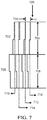
- FIG. 7 shows a first partial leaf bank 702, corresponding to first MLC 302 and second partial leaf bank 706, corresponding to second MLC 304.
- the leaves have a width 709 and heights 704 and 708.
- leaf height 704 of partial leaf bank 702 and leaf height 708 of partial leaf bank 706 are the same and are approximately 5.5 cm. It is not necessary, however, for the height of each of the leaf banks to be the same.
- the exemplary leaf mating surface machining depicted in FIG. 7 is a step feature, included in the leaves of both the first MLC 302 and second MLC 304.
- height 704 and height 708 are the same, and both equal to the variable "H".
- transmission paths such as path 710, where the incident radiation beam 106 must travel through the full height 704 of leaf bank 702, and the full height 708 of leaf bank 706, exhibiting maximum beam attenuation through a thickness of 2 x H.
- the step feature thus allows for a 33% reduction in the total height of the leaves in MLC 302 and MLC 304 to achieve the same attenuation observed by MLCs without the step feature.
- Such a feature may therefore be used to reduce the amount of material required and the weight of the leaves, thereby improving MLC speed and performance.
- the leaf height for each of the MLCs 302 304 may be approximately 3.7 cm.
- the leaf offset will result in beam 106 being attenuated by only about half of the typical amount of material at locations at the edge of aperture 212. Or, if a step feature is utilized, radiation beam 106 will be attenuated by even less material (see, for example, path 716 in FIG. 7 ).
- the exemplary MLC assemblies discussed herein may also include mechanical structures for supporting and driving the leaves, servomotors for manipulating the position of the leaves, and control systems for achieving the desired beam shape and attenuation.
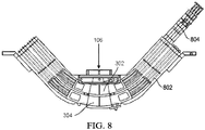
- FIG. 8 is a further depiction of the exemplary collimating system, with the inclusion of drive linkages 802 and leaf drive motor assemblies 804.
- a number of other related systems such as control systems, encoders, power cables, etc., are not depicted but may also be included.
- FIG. 9 depicts additional structures for supporting and driving the leaves of an exemplary collimating system including a top leaf support guide 902, a middle leaf support guide 904, and a bottom leaf support guide 906.
- the leaves include tabs at their top and bottom surfaces, which may ride within grooves in the leaf support guides (see, e.g., FIG. 6 ).
- guide pressure adjustment plates 908 may also be included to ensure smooth, but not loose, movement of the leaves.
- One particular implementation may also include rods 910 to further guide movement of the leaves and avoid excessive rocking.
- one implementation for the design of a leaf assembly 1002 utilizes a frame 1004, separate from attenuating material 1006.
- the frame 1004 portion of leaf assembly 1002 that will engage with leaf support guides can be made with a material different from that of attenuating material 1006.
- the attenuating material 1006 is typically a tungsten alloy or other high density material for radiation attenuation
- the frame 1004 may be made from another material, for example, stainless steel.
- Attenuating material 1006 may be designed to be an insert into frame 1004 and the two materials may be fixed together using a number of methods such as bonding, sintering or welding.
- frame 1004 does not extend all the way to the attenuating edge 1008 of leaf assembly 1002 to avoid variation in the overall attenuating properties of the leaf assembly 1002.
- control systems for multileaf collimators can be realized in digital electronic circuitry, integrated circuitry, specially designed application specific integrated circuits (ASICs), field programmable gate arrays (FPGAs) computer hardware, firmware, software, and/or combinations thereof.
- ASICs application specific integrated circuits
- FPGAs field programmable gate arrays
- These various aspects or features can include implementation in one or more computer programs that are executable and/or interpretable on a programmable system including at least one programmable processor, which can be special or general purpose, coupled to receive data and instructions from, and to transmit data and instructions to, a storage system, at least one input device, and at least one output device.
- the programmable system or computing system may include clients and servers.
- a client and server are generally remote from each other and typically interact through a communication network. The relationship of client and server arises by virtue of computer programs running on the respective computers and having a client-server relationship to each other.
- machine-readable signal refers to any signal used to provide machine instructions and/or data to a programmable processor.
- the machine-readable medium can store such machine instructions non-transitorily, such as for example as would a non-transient solid-state memory or a magnetic hard drive or any equivalent storage medium.
- the machine-readable medium can alternatively or additionally store such machine instructions in a transient manner, such as for example as would a processor cache or other random access memory associated with one or more physical processor cores.
- one or more aspects or features of the subject matter described herein can be implemented on a computer having a display device, such as for example a cathode ray tube (CRT) or a liquid crystal display (LCD) or a light emitting diode (LED) monitor for displaying information to the user and a keyboard and a pointing device, such as for example a mouse or a trackball, by which the user may provide input to the computer.
- a display device such as for example a cathode ray tube (CRT) or a liquid crystal display (LCD) or a light emitting diode (LED) monitor for displaying information to the user
- LCD liquid crystal display
- LED light emitting diode
- a keyboard and a pointing device such as for example a mouse or a trackball
- feedback provided to the user can be any form of sensory feedback, such as for example visual feedback, auditory feedback, or tactile feedback; and input from the user may be received in any form, including, but not limited to, acoustic, speech, or tactile input.
- Other possible input devices include, but are not limited to, touch screens or other touch-sensitive devices such as single or multi-point resistive or capacitive trackpads, voice recognition hardware and software, optical scanners, optical pointers, digital image capture devices and associated interpretation software, and the like.
- phrases such as "at least one of” or “one or more of” may occur followed by a conjunctive list of elements or features.
- the term “and/or” may also occur in a list of two or more elements or features. Unless otherwise implicitly or explicitly contradicted by the context in which it used, such a phrase is intended to mean any of the listed elements or features individually or any of the recited elements or features in combination with any of the other recited elements or features.
- the phrases “at least one of A and B;” “one or more of A and B;” and “A and/or B” are each intended to mean "A alone, B alone, or A and B together.”
- a similar interpretation is also intended for lists including three or more items.
- phrases “at least one of A, B, and C;” “one or more of A, B, and C;” and “A, B, and/or C” are each intended to mean “A alone, B alone, C alone, A and B together, A and C together, B and C together, or A and B and C together.”
- Use of the term “based on,” above and in the claims is intended to mean, “based at least in part on,” such that an unrecited feature or element is also permissible.
Landscapes
- Health & Medical Sciences (AREA)
- Engineering & Computer Science (AREA)
- Biomedical Technology (AREA)
- Physics & Mathematics (AREA)
- General Health & Medical Sciences (AREA)
- Pathology (AREA)
- Life Sciences & Earth Sciences (AREA)
- Animal Behavior & Ethology (AREA)
- Nuclear Medicine, Radiotherapy & Molecular Imaging (AREA)
- Public Health (AREA)
- Veterinary Medicine (AREA)
- Radiology & Medical Imaging (AREA)
- Spectroscopy & Molecular Physics (AREA)
- General Engineering & Computer Science (AREA)
- High Energy & Nuclear Physics (AREA)
- Radiation-Therapy Devices (AREA)
- Analysing Materials By The Use Of Radiation (AREA)
- Apparatus For Radiation Diagnosis (AREA)
Description
- The present disclosure relates to systems for collimating or shaping a radiation beam. Collimators are typically made from high atomic number materials, such as tungsten, and are therefore able to attenuate a significant amount of radiation. Collimators may be used, for example, to shape a radiation beam for the purpose of providing precise medical radiation therapy.
- Double collimator systems are disclosed for example in
US 6 600 810 as well asUS 2014 112 453 . - In one implementation, a collimating system collimates a radiation beam from a radiation source, the beam being directed at a target. The collimating system includes a first multileaf collimator having a number of leaves, and a second multileaf collimator having a number of leaves. The collimating system is configured such that the radiation beam will pass through the first multileaf collimator before passing through the second multileaf collimator, and pass through the second multileaf collimator before hitting the target. The leaves of the first multileaf collimator and the leaves of the second multileaf collimator are configured to move independently of one another. At least one of the first multileaf collimator and the second multileaf collimator is double focused.
- The first multileaf collimator and the second multileaf collimator can both be double focused, configured to be slightly defocused to decrease radiation leakage through interleaf gaps, or can be configured to be defocused by approximately 1 centimeter.
- The first multileaf collimator has a focus point and the second multileaf collimator has a focus point and the focus point of the first multileaf collimator can be different from the focus point of the second multileaf collimator. The differing focus points of the first multileaf collimator and the second multileaf collimator can improve the match of penumbra between the first multileaf collimator and the second multileaf collimator. The focus point of the first multileaf collimator can be at the effective source point and the focus point of the second multileaf collimator moved off of the effective source point. The first multileaf collimator and second multileaf collimator can further be configured to collimate a beam thinner than the widths of the leaves of the first and second multileaf collimators.
- The leaves of the first multileaf collimator can have approximately the same width as the leaves of the second multileaf collimator. The leaves of the first multileaf collimator can be immediately adjacent to one another and the leaves of the second multileaf collimator can be immediately adjacent to one another.
- The gaps between adjacent leaves in the first multileaf collimator and gaps between adjacent leaves in the second multileaf collimator can be minimized to reduce radiation leakage.
- The leaves of both the first multileaf collimator and the second multileaf collimator can be approximately 4 mm wide.
- The leaves of the first multileaf collimator and the leaves of the second multileaf collimator can be offset by approximately 50% of their width.
- The thickness of the leaves of the first multileaf collimator and the thickness of the leaves of the second multileaf collimator can be approximately the same, can be each sufficient to fully attenuate the radiation beam for medical radiation therapy, or can be approximately 5.5 cm.
- The mating surfaces of the leaves can be straight edged, machined to provide a tongue and groove interface, or machined to provide a step interface.
- The leaves of the first and second multileaf collimators can include leaf assemblies utilizing a frame separate from an attenuating material. The frame can be made from a stainless steel alloy and the attenuating material can be a tungsten alloy.
- The first multileaf collimator can have two banks and each bank includes 34 leaves and the second multileaf collimator can have two banks and each bank includes 35 leaves.
- The edge of the collimating system closest to the target can be less than 60 cm from a radiation isocenter. The collimating system can optionally not include collimator jaws.
- The details of one or more variations of the subject matter described herein are set forth in the accompanying drawings and the description below. Other features and advantages of the subject matter described herein will be apparent from the description and drawings, and from the claims. While certain features of the currently disclosed subject matter are described for illustrative purposes in relation to particular implementations, it should be readily understood that such features are not intended to be limiting. The claims that follow this disclosure are intended to define the scope of the protected subject matter, other embodiments being merely exemplary.
- The accompanying drawings, which are incorporated in and constitute a part of this specification, show certain aspects of the subject matter disclosed herein and, together with the description, help explain some of the principles associated with the disclosed implementations. In the drawings,
-
Figure 1 is a simplified diagram illustrating an exemplary use of a collimating device with a radiation source. -
Figure 2 is a simplified illustration of an exemplary multileaf collimator and the manner in which it can create an aperture. -
Figure 3 is a simplified illustration of an exemplary double-stacked collimating device in accordance with certain aspects of the present disclosure. -
Figures 4A and 4B are simplified illustrations of a manner in which a double stacked collimating device may collimate a radiation beam -
Figure 5 is a simplified isometric illustration of an exemplary double-stacked collimating device in accordance with certain aspects of the present disclosure. -
Figure 6 is a simplified illustration of an exemplary double-stacked collimating device in accordance with certain aspects of the present disclosure. -
Figure 7 is a simplified illustration of an exemplary double-stacked collimating device utilizing stepped leaf designs. -
Figure 8 is a simplified illustration of an exemplary double-stacked collimating device with additional drive hardware in accordance with certain aspects of the present disclosure. -
Figure 9 is a simplified illustration of an exemplary double-stacked collimating device with additional guide hardware accordance with certain aspects of the present disclosure. -
Figure 10 is a simplified illustration of an exemplary leaf assembly in accordance with certain aspects of the present disclosure. - An exemplary use for a collimating device/system is depicted in
FIG. 1 . As shown,collimating device 102 is placed in the path of aradiation beam 106 emanating from aradiation source 104.Collimating device 102 enables selective attenuation of theradiation beam 106 as it travels towardtarget 108. Theradiation source 104 may be, for example, a radioisotope, a heavy ion accelerator, a linear accelerator for producing an electron or photon beam, or the like. While the technology of the present disclosure may be used in any field where radiation beams are utilized, an embodiment described herein depicts a medical patient astarget 108. -
FIG. 2 depicts a particular type of collimating device known as a Multi-Leaf Collimator (or MLC). Theexemplary MLC 200 shown includes a bank ofmovable leaves 202 opposite a second bank ofmovable leaves 204. In such a device, eachleaf 206 is independently adjustable in order to enable the forming of anaperture 212, which collimates the beam into the desired shape for treatment. - Each leaf in
MLC 200 may be described as having awidth 208 and a height 110 (height is shown inFIG. 1 ). Theheight 110 may also be described as the "thickness" of a leaf and is important in determining the amount of attenuation ofbeam 106 byMLC 200. The amount of attenuation is also affected by the material that the leaves of the MLC are made of and therefore high-attenuating materials are used such as tungsten, tungsten alloys, tantalum, tantalum alloys, lead, lead alloys and the like. - An exemplary collimating system contemplated by the present disclosure is depicted in
FIG. 3 and comprises multiple "stacked" MLCs. For example, the embodiment depicted includes afirst MLC 302 and asecond MLC 304. The MLCs are stacked such that their attenuation values are additive with respect toradiation beam 106. The first MLC 302 is positioned closer toradiation source 104 thansecond MLC 304, so thatradiation beam 106 passes throughfirst MLC 302 before passing throughsecond MLC 304. The embodiments depicted herein show two stacked MLCs but it is contemplated that additional MLCs could be added (e.g., a stack of three) following the general teachings of the present disclosure. - While it is common for collimating devices to be placed close to
radiation source 104, the present disclosure contemplates an embodiment that moves the collimating device closer to the target or patient. For example, a preferred implementation of the present disclosure moves the collimating device as close to the target as possible, without restricting the desired bore or volume to be occupied by the target/patient. In one preferred implementation, the edge of the collimating device closest to target 108 (i.e., the edge of thesecond MLC 304 that is farthest from radiation source 104) is less than 60 cm from isocenter, and preferably about 50 cm from isocenter. It is contemplated that such a design facilitates positioning of the collimating device during assembly and decreases beam penumbra. -
FIG. 4A and FIG. 4B are simplified illustrations of how beams may be collimated with an exemplary double-stacked MLC system. As shown in both figures, the leaves in thefirst MLC 302 andsecond MLC 304 are offset by one half the width of the leaves, or by approximately one half of the width of the leaves. The leaves infirst MLC 302 andsecond MLC 304 can be moved independently of one another. InFIG. 4A , one leaf infirst MLC 302 and one leaf insecond MLC 304 can be retracted to create the smallest aperture through whichbeam 106 may pass (in the dimension corresponding to the width of the leaves). As a result, the leaves of the MLCs are offset in a manner to allow for collimation of a beam thinner than the widths of the leaves of each of the first and second multileaf collimators. - In one particular implementation, the width of such a beam may be 4.15 mm when the width of the leaves in both
first MLC 302 andsecond MLC 304 are approximately 8.3 mm.FIG. 4B shows that when two leaves of one of the MLCs are retracted and an overlapping leaf in the other MLC is retracted, the second smallest aperture through whichradiation beam 106 may pass is created, for example, a beam having a width of 8.3 mm. - In one implementation, the MLCs are stacked, the leaves in each MLC are approximately the same width, and the leaves in
first MLC 302 are offset from the leaves insecond MLC 304 by approximately one-half of their width (as shown inFIG. 4 ). The MLC leaves in such an implementation may be designed to be approximately twice the width of a typical MLC, while still achieving approximately the same resolution. For example, to achieve a 5mm resolution at isocenter, a typical single MLC will require leaves approximately 2.5mm wide, while in a double-stacked design with offset, the leaves may be approximately 5 mm wide and achieve the same resolution. Such a design may be desirable for ease of machining and to provide more material for equipment connecting to or interfacing with the leaves. -
FIG. 5 is an isometric view of the exemplary collimating system ofFIG. 3 showing doublestacked MLCs - Given the beam collimating features shown in
FIG. 4 , and the importance of beam attenuation described herein, preferred implementations of the present disclosure utilize leaf heights forfirst MLC 302 andsecond MLC 304 that are the same, or approximately the same. Because both thefirst MLC 302 andsecond MLC 304 are responsible for shapingradiation beam 106, bothfirst MLC 302 andsecond MLC 304 are each preferably designed with leaf heights sufficient to fully attenuate theradiation beam 106, as an example, for medical radiation therapy. In one particular implementation, the leaves of bothfirst MLC 302 andsecond MLC 304 are made with a tungsten alloy of 17.5 gm/cc or higher density (e.g., 5:5:90 Cu:Ni:W) and are each approximately 5.5 cm thick. A preferred exemplary collimating system may include 34 leaves in each bank of thefirst MLC 302, and 35 leaves in each bank of thesecond MLC 304, although different resolutions and numbers of leaves in each bank are contemplated. - It is preferable that the MLCs used with the technology of the present disclosure be double focused, as shown in the drawings (as opposed to using non-focused collimators such as those having linear leaf motion and rounded leaf ends). MLCs are double focused when all of the beam defining surfaces of the leaves project back to the radiation source. For example, with reference to
FIG. 1 ,radiation beam 106 fans out fromradiation source 104. Because the exemplary collimating systems utilize curved leaves that retract along an arc (e.g., as shown inFIGS. 1 ,3 ), the edges of the leaves, as they retract, always represent a line projecting back toradiation source 104. With such a design, the entire thickness of the leaves will attenuatebeam 106 as it passes through the collimating device, providing for a sharper beam edge with low penumbra regardless of how far the leaves are retracted. - When all four of the leaf surfaces that collimate
beam 106 project back to the radiation source, the collimating system is "double" focused.FIG. 5 illustrates a manner by which the MLCs may focusbeam 106 in the other dimension - by virtue of the leaves' width increasing with distance fromradiation source 104. InFIG. 5 , for example, the width of the leaves at the top ofMLC 302 is the thinnest. The width is larger at the bottom of the leaves ofMLC 302, larger still at the top of the leaves insecond MLC 304, and largest at the bottom of the leaves inMLC 304. This design is also illustrated inFIG. 6 . - In one implementation, the focusing of the leaf designs is purposefully defocused slightly. For example, the leaf surfaces may designed to project to a point one to two centimeters above or below the actual radiation source. This slight defocusing can significantly decrease radiation leakage through the space between the leaves (i.e., interleaf gaps), while having only a small impact on beam penumbra.
- The
first MLC 302 andsecond MLC 304 have different focus points. The arcs on which the MLCs travel would therefore intersect at some point but within their boundaries they can be designed to have sufficient clearance from one another. The differing focus points may be chosen to improve the match of penumbra between the first multileaf collimator and the second multileaf collimator even though they are at different distances from the source. For example, the focus of the first MLC can be placed at the effective source point and the focus of the second MLC can be moved off of the effective source point. Such an exemplary design would increase the penumbra of the lower MLC to better match the penumbra of the upper MLC and provide better dosimetric matching of the beam edges shaped by first MLC and second MLC. - With conventional, non-focused MLCs, collimator jaws are necessary to prevent radiation leakage outside of beam apertures. As the rounded leaf ends of a conventional MLC are poor at blocking radiation even when completely closed, closed leaf ends are often moved to a position where they are blocked by the conventional collimator jaws. The utilization of double focused leaves limits leaf end leakage and penumbra to an extent that an adjacent, stacked MLC of reasonable thickness (having an offset leaf-meeting location) will be sufficient to block transmission so that conventional collimator jaws are not necessary. The present disclosure thus contemplates collimating systems that do not include collimator jaws.
- While preferred implementations of the present disclosure utilize double focused MLCs, it is contemplated that single focused or unfocused MLCs may also be utilized, or a mixture of focusing types may be used across multiple stacked MLCs.
- When comparing the width of the leaves of
first MLC 302 andsecond MLC 304 in a focused implementation, it is noted above that the leaf width continually increases with distance fromradiation source 104. That being said, a preferred implementation of the present disclosure includes leaf designs with approximately the same width in thefirst MLC 302 as in thesecond MLC 304. When described in this way, "approximately the same width" means that the bottom width of the leaves infirst MLC 302 is approximately the same (i.e., just slightly smaller) than the top width of the leaves insecond MLC 304. Stated another way, focused leaves in the first and second MLCs can be thought of as having approximately the same width - including a small additional width being added along the leaves as they extend further fromradiation source 104, as is necessary to provide a focused design (e.g., as shown inFIGS. 5 and6 ). - While a preferred implementation utilizes leaf designs where leaf widths in
first MLC 302 andsecond MLC 304 are approximately the same, the present disclosure contemplate designs where the leaf widths can be different between the stacked MLCs. - In a preferred implementation of the present disclosure, the leaves of
first MLC 302 are immediately adjacent to each other or touching, and the leaves ofsecond MLC 304 are immediately adjacent to one another or touching. In this implementation, the gaps between adjacent leaves in bothfirst MLC 302 andsecond MLC 304 are minimized in a manner that will minimize radiation leakage between the leaves, yet still allow for relative motion. This type of implementation is illustrated in, for example,FIGS. 4 ,5 , and6 . - Because the leaves of an MLC are able to move independently, there is necessarily a small gap between them through which some radiation may pass. The collimating system of the present disclosure contemplates that the leaves of
first MLC 302 and the leaves ofsecond MLC 304 are preferably arranged so the gaps between leaves are not aligned soradiation beam 106 may not transmit through a leaf gap infirst MLC 302 and then directly through a leaf gap insecond MLC 304. Instead, the leaves offirst MLC 302 are preferably offset from the leaves ofsecond MLC 304 so that there is no straight-line path for the beam to travel through the inter-leaf gaps of both of MLCs. See, for example,FIGS. 4 ,5 and6 . - In an exemplary embodiment, the leaves of
first MLC 302 andsecond MLC 304 are offset by approximately 50% of their width so as to provide the greatest separation between the inter-leaf gaps of thefirst MLC 302 and thesecond MLC 304. Offsets of less than 50% of the leaf width are contemplated by the present disclosure but an offset is preferably utilized and is preferably is greater than 10% of the width of the leaves. - In typical collimating systems with only one MLC, inter-leaf leakage must be prevented through complex machining of the leaves in the location where they mate or abut one another. For example, tongue and groove or stepped designs may be employed to interrupt an otherwise linear inter-leaf gap that could allow significant beam leakage. The collimating system of the present disclosure contemplates the ability to eliminate such additional machining because, even if straight-edged leaves are utilized, the leakage path through the collimating system will be in interrupted by virtue of the previously described overlap or offset of the leaves between
first MLC 302 andsecond MLC 304. A preferred implementation includes simple, straight-edged leaves without additional machining or features to block interleaf leakage. Such a design may also result in a more uniform leaf edge and decreased beam penumbra. - In an alternative embodiment of the presently described collimating system, despite having multiple MLCs and leaf offsets, the mating surfaces of the leaves may be machined to further decrease the leakage paths and enable reduction of the height of the MLCs. Any configuration of nonlinear surfaces may prove beneficial, such as a tongue and groove design, or the like. In an exemplary embodiment, depicted in
FIG. 7 , steps are machined into the mating surfaces of the leaves.FIG. 7 shows a firstpartial leaf bank 702, corresponding tofirst MLC 302 and secondpartial leaf bank 706, corresponding tosecond MLC 304. In the depicted embodiment, the leaves have a width 709 andheights leaf height 704 ofpartial leaf bank 702 andleaf height 708 ofpartial leaf bank 706 are the same and are approximately 5.5 cm. It is not necessary, however, for the height of each of the leaf banks to be the same. - The exemplary leaf mating surface machining depicted in
FIG. 7 is a step feature, included in the leaves of both thefirst MLC 302 andsecond MLC 304. For the purposes of simplified discussion we will assume thatheight 704 andheight 708 are the same, and both equal to the variable "H". In the example ofFIG. 7 , there will exist transmission paths such aspath 710, where theincident radiation beam 106 must travel through thefull height 704 ofleaf bank 702, and thefull height 708 ofleaf bank 706, exhibiting maximum beam attenuation through a thickness of 2 x H. However, there are also transmission paths that will encounter inter-leaf gaps, such aspaths 712 and 714, which will exhibit decreased attenuation as a result of only passing through a total leaf thickness of H + 1/2 H = 3/2 H. Nevertheless, this attenuation thickness of 3/2 H is greater than the thickness of only 1 H that would be encountered in a double stacked collimating system without the "step" feature. The step feature thus allows for a 33% reduction in the total height of the leaves inMLC 302 andMLC 304 to achieve the same attenuation observed by MLCs without the step feature. Such a feature may therefore be used to reduce the amount of material required and the weight of the leaves, thereby improving MLC speed and performance. As an example, the leaf height for each of theMLCs 302 304 may be approximately 3.7 cm. - In a double-stacked design, with offset, the leaf offset will result in
beam 106 being attenuated by only about half of the typical amount of material at locations at the edge ofaperture 212. Or, if a step feature is utilized,radiation beam 106 will be attenuated by even less material (see, for example,path 716 inFIG. 7 ). - The exemplary MLC assemblies discussed herein may also include mechanical structures for supporting and driving the leaves, servomotors for manipulating the position of the leaves, and control systems for achieving the desired beam shape and attenuation.
FIG. 8 is a further depiction of the exemplary collimating system, with the inclusion ofdrive linkages 802 and leafdrive motor assemblies 804. A number of other related systems such as control systems, encoders, power cables, etc., are not depicted but may also be included. -
FIG. 9 depicts additional structures for supporting and driving the leaves of an exemplary collimating system including a topleaf support guide 902, a middleleaf support guide 904, and a bottomleaf support guide 906. In one embodiment, the leaves include tabs at their top and bottom surfaces, which may ride within grooves in the leaf support guides (see, e.g.,FIG. 6 ). In addition, guidepressure adjustment plates 908 may also be included to ensure smooth, but not loose, movement of the leaves. One particular implementation may also includerods 910 to further guide movement of the leaves and avoid excessive rocking. - Referring now to
FIG. 10 , one implementation for the design of aleaf assembly 1002 utilizes aframe 1004, separate from attenuatingmaterial 1006. In such a design, theframe 1004 portion ofleaf assembly 1002 that will engage with leaf support guides can be made with a material different from that of attenuatingmaterial 1006. While the attenuatingmaterial 1006 is typically a tungsten alloy or other high density material for radiation attenuation, theframe 1004 may be made from another material, for example, stainless steel.Attenuating material 1006 may be designed to be an insert intoframe 1004 and the two materials may be fixed together using a number of methods such as bonding, sintering or welding. Preferably,frame 1004 does not extend all the way to the attenuatingedge 1008 ofleaf assembly 1002 to avoid variation in the overall attenuating properties of theleaf assembly 1002. - One or more aspects or features of the subject matter described herein, for example, the control systems for multileaf collimators, can be realized in digital electronic circuitry, integrated circuitry, specially designed application specific integrated circuits (ASICs), field programmable gate arrays (FPGAs) computer hardware, firmware, software, and/or combinations thereof. These various aspects or features can include implementation in one or more computer programs that are executable and/or interpretable on a programmable system including at least one programmable processor, which can be special or general purpose, coupled to receive data and instructions from, and to transmit data and instructions to, a storage system, at least one input device, and at least one output device. The programmable system or computing system may include clients and servers. A client and server are generally remote from each other and typically interact through a communication network. The relationship of client and server arises by virtue of computer programs running on the respective computers and having a client-server relationship to each other.
- These computer programs, which can also be referred to programs, software, software applications, applications, components, or code, include machine instructions for a programmable processor, and can be implemented in a high-level procedural language, an object-oriented programming language, a functional programming language, a logical programming language, and/or in assembly/machine language. As used herein, the term "machine-readable medium" (or "computer readable medium") refers to any computer program product, apparatus and/or device, such as for example magnetic discs, optical disks, memory, and Programmable Logic Devices (PLDs), used to provide machine instructions and/or data to a programmable processor, including a machine-readable medium that receives machine instructions as a machine-readable signal. The term "machine-readable signal" (or "computer readable signal") refers to any signal used to provide machine instructions and/or data to a programmable processor. The machine-readable medium can store such machine instructions non-transitorily, such as for example as would a non-transient solid-state memory or a magnetic hard drive or any equivalent storage medium. The machine-readable medium can alternatively or additionally store such machine instructions in a transient manner, such as for example as would a processor cache or other random access memory associated with one or more physical processor cores.
- To provide for interaction with a user, one or more aspects or features of the subject matter described herein can be implemented on a computer having a display device, such as for example a cathode ray tube (CRT) or a liquid crystal display (LCD) or a light emitting diode (LED) monitor for displaying information to the user and a keyboard and a pointing device, such as for example a mouse or a trackball, by which the user may provide input to the computer. Other kinds of devices can be used to provide for interaction with a user as well. For example, feedback provided to the user can be any form of sensory feedback, such as for example visual feedback, auditory feedback, or tactile feedback; and input from the user may be received in any form, including, but not limited to, acoustic, speech, or tactile input. Other possible input devices include, but are not limited to, touch screens or other touch-sensitive devices such as single or multi-point resistive or capacitive trackpads, voice recognition hardware and software, optical scanners, optical pointers, digital image capture devices and associated interpretation software, and the like.
- In the descriptions above and in the claims, phrases such as "at least one of" or "one or more of" may occur followed by a conjunctive list of elements or features. The term "and/or" may also occur in a list of two or more elements or features. Unless otherwise implicitly or explicitly contradicted by the context in which it used, such a phrase is intended to mean any of the listed elements or features individually or any of the recited elements or features in combination with any of the other recited elements or features. For example, the phrases "at least one of A and B;" "one or more of A and B;" and "A and/or B" are each intended to mean "A alone, B alone, or A and B together." A similar interpretation is also intended for lists including three or more items. For example, the phrases "at least one of A, B, and C;" "one or more of A, B, and C;" and "A, B, and/or C" are each intended to mean "A alone, B alone, C alone, A and B together, A and C together, B and C together, or A and B and C together." Use of the term "based on," above and in the claims is intended to mean, "based at least in part on," such that an unrecited feature or element is also permissible.
Claims (15)
- A collimating system for collimating a radiation beam from a radiation source, the beam being directed at a target, comprising:a first multileaf collimator having a plurality of leaves;a second multileaf collimator having a plurality of leaves and configured such that the radiation beam will pass through the first multileaf collimator before passing through the second multileaf collimator, and pass through the second multileaf collimator before hitting the target;wherein the leaves of the first multileaf collimator and the leaves of the second multileaf collimator are configured to move independently of one another;wherein at least one of the first multileaf collimator and the second multileaf collimator is double focused,characterised in that:
the first multileaf collimator has a focus point and the second multileaf collimator has a focus point and the focus point of the first multileaf collimator is different from the focus point of the second multileaf collimator. - The collimating system of claim 1 wherein the first multileaf collimator and the second multileaf collimator are both double focused.
- The collimating system of claim 2 wherein the first multileaf collimator and the second multileaf collimator are configured to be slightly defocused to decrease radiation leakage through interleaf gaps.
- The collimating system of claim 3 wherein the first multileaf collimator and the second multileaf collimator are configured to be defocused by approximately 1 centimeter.
- The collimating system of claim 1 wherein the differing focus points of the first multileaf collimator and the second multileaf collimator improve the match of penumbra between the first multileaf collimator and the second multileaf collimator.
- The collimating system of claim 1 wherein the focus point of the first multileaf collimator is at the effective source point and the focus point of the second multileaf collimator is moved off of the effective source point.
- The collimating system as in any preceding claim wherein the first multileaf collimator and second multileaf collimator are further configured to collimate a beam thinner than the widths of the leaves of the first and second multileaf collimators.
- The collimating system as in any preceding claim wherein the leaves of the first multileaf collimator have approximately the same width as the leaves of the second multileaf collimator.
- The collimating system as in any preceding claim wherein the leaves of the first multileaf collimator are immediately adjacent to one another and the leaves of the second multileaf collimator are immediately adjacent to one another.
- The collimating system as in any preceding claim wherein the thickness of the leaves of the first multileaf collimator and the thickness of the leaves of the second multileaf collimator are each sufficient to fully attenuate the radiation beam for medical radiation therapy.
- The collimating system as in any preceding claim wherein the mating surfaces of the leaves are straight edged, or
wherein the mating surfaces of the leaves are machined to provide a tongue and groove interface, or
wherein the mating surfaces of the leaves are machined to provide a step interface. - The collimating system as in any preceding claim wherein leaves of the first and second multileaf collimators comprise leaf assemblies utilizing a frame separate from an attenuating material.
- The collimating system of claim 12 wherein the frame is made from a stainless steel alloy and the attenuating material is a tungsten alloy.
- The collimating system as in any preceding claim wherein the edge of the collimating system closest to the target is less than 60 cm from a radiation isocenter.
- The collimating system as in any preceding claim wherein the system does not include collimator jaws.
Applications Claiming Priority (2)
| Application Number | Priority Date | Filing Date | Title |
|---|---|---|---|
| US201562259570P | 2015-11-24 | 2015-11-24 | |
| PCT/US2016/063416 WO2017091621A1 (en) | 2015-11-24 | 2016-11-22 | Radiation beam collimating systems and methods |
Publications (2)
| Publication Number | Publication Date |
|---|---|
| EP3380192A1 EP3380192A1 (en) | 2018-10-03 |
| EP3380192B1 true EP3380192B1 (en) | 2019-11-06 |
Family
ID=57530851
Family Applications (1)
| Application Number | Title | Priority Date | Filing Date |
|---|---|---|---|
| EP16809273.2A Revoked EP3380192B1 (en) | 2015-11-24 | 2016-11-22 | Radiation beam collimating systems |
Country Status (8)
| Country | Link |
|---|---|
| US (2) | US9966160B2 (en) |
| EP (1) | EP3380192B1 (en) |
| JP (1) | JP2018535022A (en) |
| KR (1) | KR20180087310A (en) |
| CN (1) | CN108367160A (en) |
| AU (1) | AU2016361432A1 (en) |
| CA (1) | CA3005964A1 (en) |
| WO (1) | WO2017091621A1 (en) |
Families Citing this family (23)
| Publication number | Priority date | Publication date | Assignee | Title |
|---|---|---|---|---|
| AU2005216070B2 (en) | 2004-02-20 | 2012-01-19 | University Of Florida Research Foundation, Inc. | System for delivering conformal radiation therapy while simultaneously imaging soft tissue |
| JP6382208B2 (en) | 2012-10-26 | 2018-08-29 | ビューレイ・テクノロジーズ・インコーポレイテッドViewRay Technologies, Inc. | System and computer program product |
| CA2976331C (en) | 2015-02-11 | 2024-02-27 | Viewray Technologies, Inc. | Planning and control for magnetic resonance guided radiation therapy |
| US10398911B2 (en) * | 2015-09-25 | 2019-09-03 | Varian Medical Systems Internationl AG | Method and apparatus for using a multi-layer multi-leaf collimation system |
| CN109310879A (en) | 2016-03-02 | 2019-02-05 | 优瑞技术公司 | Particle Therapy Using Magnetic Resonance Imaging |
| RU2019121943A (en) * | 2016-12-13 | 2021-01-15 | Вьюрэй Текнолоджиз, Инк. | SYSTEMS AND METHODS OF RADIOTHERAPY |
| CN210131259U (en) * | 2017-09-20 | 2020-03-10 | 西安大医集团股份有限公司 | Multi-leaf collimator and radiotherapy head |
| JP7127126B2 (en) | 2017-12-06 | 2022-08-29 | ビューレイ・テクノロジーズ・インコーポレイテッド | Radiation therapy system, method and software |
| US11209509B2 (en) | 2018-05-16 | 2021-12-28 | Viewray Technologies, Inc. | Resistive electromagnet systems and methods |
| US10709905B2 (en) * | 2018-06-29 | 2020-07-14 | Victor Hernandez | Method of calculating a tongue-and-groove effect of a multi-leaf collimator |
| US10888713B2 (en) * | 2018-12-28 | 2021-01-12 | Varian Medical Systems, Inc. | Multileaf collimator with alternating trapezoidal leaf geometry design |
| US10974071B2 (en) * | 2019-04-30 | 2021-04-13 | Varian Medical Systems, Inc. | Multileaf collimator cone enabling stereotactic radiosurgery |
| WO2021016757A1 (en) | 2019-07-26 | 2021-02-04 | Shanghai United Imaging Healthcare Co., Ltd. | Radiation treatment system and operating method thereof |
| WO2021108684A1 (en) * | 2019-11-25 | 2021-06-03 | The Regents Of The University Of California | Systems and methods for dynamic control of radiation dose in radiation therapy |
| US20210265071A1 (en) * | 2020-02-26 | 2021-08-26 | Varian Medical Systems International Ag | Beam-blocking leaf and multileaf collimator containing same |
| GB2592984B (en) | 2020-03-13 | 2022-06-22 | Elekta ltd | Leaf drive mount for a multi-leaf collimator |
| GB2594446B (en) | 2020-03-13 | 2022-06-08 | Elekta ltd | Multi-leaf collimator module |
| EP4117776A1 (en) | 2020-03-13 | 2023-01-18 | Elekta Limited | Multi-leaf collimator |
| GB2592990B (en) | 2020-03-13 | 2022-03-16 | Elekta ltd | Leaf actuator for a multi-leaf collimator |
| GB2592987A (en) * | 2020-03-13 | 2021-09-15 | Elekta ltd | Leaf for a multi-leaf collimator |
| DE102021209248B3 (en) | 2021-08-24 | 2023-02-16 | Siemens Healthcare Gmbh | Slat for collimating therapy radiation |
| DE102021209254B4 (en) | 2021-08-24 | 2023-04-27 | Siemens Healthcare Gmbh | Slat for collimating therapy radiation |
| DE102022203544A1 (en) | 2022-04-08 | 2023-10-12 | Siemens Healthcare Gmbh | Lamella for collimating therapeutic radiation |
Family Cites Families (145)
| Publication number | Priority date | Publication date | Assignee | Title |
|---|---|---|---|---|
| US4694837A (en) | 1985-08-09 | 1987-09-22 | Picker International, Inc. | Cardiac and respiratory gated magnetic resonance imaging |
| EP0371303B1 (en) * | 1988-11-29 | 1994-04-27 | Varian International AG. | Radiation therapy apparatus |
| US5734384A (en) | 1991-11-29 | 1998-03-31 | Picker International, Inc. | Cross-referenced sectioning and reprojection of diagnostic image volumes |
| US5394452A (en) * | 1992-03-19 | 1995-02-28 | Wisconsin Alumni Research Foundation | Verification system for radiation therapy |
| US5317616A (en) | 1992-03-19 | 1994-05-31 | Wisconsin Alumni Research Foundation | Method and apparatus for radiation therapy |
| US5216255A (en) | 1992-03-31 | 1993-06-01 | Siemens Medical Laboratories | Beam profile generator for photon radiation |
| US5332908A (en) | 1992-03-31 | 1994-07-26 | Siemens Medical Laboratories, Inc. | Method for dynamic beam profile generation |
| US5596619A (en) * | 1992-08-21 | 1997-01-21 | Nomos Corporation | Method and apparatus for conformal radiation therapy |
| DE69425762T2 (en) | 1993-06-09 | 2001-04-26 | Wisconsin Alumni Research Foundation, Madison | Radiation therapy system |
| US5373844A (en) | 1993-06-14 | 1994-12-20 | The Regents Of The University Of California | Inverse treatment planning method and apparatus for stereotactic radiosurgery |
| US5458125A (en) | 1994-01-28 | 1995-10-17 | Board Of Directors Of The Leland Standford Jr. University | Treatment planning method and apparatus for radiosurgery and radiation therapy |
| US5538494A (en) | 1994-03-17 | 1996-07-23 | Hitachi, Ltd. | Radioactive beam irradiation method and apparatus taking movement of the irradiation area into consideration |
| US5537452A (en) | 1994-05-10 | 1996-07-16 | Shepherd; Joseph S. | Radiation therapy and radiation surgery treatment system and methods of use of same |
| US5513238A (en) | 1994-10-11 | 1996-04-30 | Radionics, Inc. | Automatic planning for radiation dosimetry |
| US5555283A (en) | 1995-06-07 | 1996-09-10 | Board Of Regents Of The University Of Texas System | Computer-controlled miniature multileaf collimator |
| US6351659B1 (en) | 1995-09-28 | 2002-02-26 | Brainlab Med. Computersysteme Gmbh | Neuro-navigation system |
| GB9520564D0 (en) | 1995-10-07 | 1995-12-13 | Philips Electronics Nv | Apparatus for treating a patient |
| JPH09154961A (en) | 1995-12-07 | 1997-06-17 | Toshiba Medical Eng Co Ltd | Radiation treatment planning method |
| US5602892A (en) | 1996-03-21 | 1997-02-11 | Llacer; Jorge | Method for optimization of radiation therapy planning |
| US6038283A (en) | 1996-10-24 | 2000-03-14 | Nomos Corporation | Planning method and apparatus for radiation dosimetry |
| US5757881A (en) * | 1997-01-06 | 1998-05-26 | Siemens Business Communication Systems, Inc. | Redundant field-defining arrays for a radiation system |
| DE19715202B4 (en) | 1997-04-11 | 2006-02-02 | Brainlab Ag | Referencing device with a mouthpiece |
| SE512603C2 (en) | 1997-06-19 | 2000-04-10 | Elekta Ab | Method and device for automated dose planning |
| US6052430A (en) | 1997-09-25 | 2000-04-18 | Siemens Medical Systems, Inc. | Dynamic sub-space intensity modulation |
| US6526123B2 (en) | 1997-09-29 | 2003-02-25 | Moshe Ein-Gal | Multiple layer multileaf collimator |
| US6198957B1 (en) | 1997-12-19 | 2001-03-06 | Varian, Inc. | Radiotherapy machine including magnetic resonance imaging system |
| US6240162B1 (en) | 1998-01-15 | 2001-05-29 | Siemens Medical Systems, Inc. | Precision dosimetry in an intensity modulated radiation treatment system |
| US6327490B1 (en) | 1998-02-27 | 2001-12-04 | Varian Medical Systems, Inc. | Brachytherapy system for prostate cancer treatment with computer implemented systems and processes to facilitate pre-implantation planning and post-implantation evaluations with storage of multiple plan variations for a single patient |
| US6381486B1 (en) | 1999-01-08 | 2002-04-30 | Wisconsin Alumni Research Foundation | Magnetic resonance angiography with vessel segmentation |
| US6487435B2 (en) | 1998-04-10 | 2002-11-26 | Wisconsin Alumni Research Foundation | Magnetic resonance angiography using undersampled 3D projection imaging |
| US6175761B1 (en) | 1998-04-21 | 2001-01-16 | Bechtel Bwxt Idaho, Llc | Methods and computer executable instructions for rapidly calculating simulated particle transport through geometrically modeled treatment volumes having uniform volume elements for use in radiotherapy |
| US6393096B1 (en) | 1998-05-27 | 2002-05-21 | Nomos Corporation | Planning method and apparatus for radiation dosimetry |
| US7096055B1 (en) | 1998-06-24 | 2006-08-22 | Achim Schweikard | Method to control delivery of radiation therapy |
| DE19829224B4 (en) | 1998-06-30 | 2005-12-15 | Brainlab Ag | Method for localizing treatment goals in the area of soft body parts |
| KR20010072304A (en) | 1998-08-06 | 2001-07-31 | 리차드 에이취 리저 | Method for preparing a radiation therapy plan |
| WO2000007669A1 (en) | 1998-08-06 | 2000-02-17 | Wisconsin Alumni Research Foundation | Delivery modification system for radiation therapy |
| US6600810B1 (en) * | 1998-08-10 | 2003-07-29 | Siemens Medical Solutions Usa, Inc. | Multiple layer multileaf collimator design to improve resolution and reduce leakage |
| US6112112A (en) | 1998-09-18 | 2000-08-29 | Arch Development Corporation | Method and system for the assessment of tumor extent in magnetic resonance images |
| DE19848765C2 (en) | 1998-10-22 | 2000-12-21 | Brainlab Med Computersyst Gmbh | Position verification in camera images |
| US6980679B2 (en) | 1998-10-23 | 2005-12-27 | Varian Medical System Technologies, Inc. | Method and system for monitoring breathing activity of a subject |
| US6621889B1 (en) | 1998-10-23 | 2003-09-16 | Varian Medical Systems, Inc. | Method and system for predictive physiological gating of radiation therapy |
| US6937696B1 (en) | 1998-10-23 | 2005-08-30 | Varian Medical Systems Technologies, Inc. | Method and system for predictive physiological gating |
| US6778850B1 (en) | 1999-03-16 | 2004-08-17 | Accuray, Inc. | Frameless radiosurgery treatment system and method |
| US6144875A (en) | 1999-03-16 | 2000-11-07 | Accuray Incorporated | Apparatus and method for compensating for respiratory and patient motion during treatment |
| US6501981B1 (en) | 1999-03-16 | 2002-12-31 | Accuray, Inc. | Apparatus and method for compensating for respiratory and patient motions during treatment |
| WO2000059576A1 (en) | 1999-04-02 | 2000-10-12 | Wisconsin Alumni Research Foundation | Megavoltage computed tomography during radiotherapy |
| DE19917867B4 (en) | 1999-04-20 | 2005-04-21 | Brainlab Ag | Method and device for image support in the treatment of treatment objectives with integration of X-ray detection and navigation system |
| US6512813B1 (en) | 1999-05-03 | 2003-01-28 | Franz Krispel | Rotating stereotactic treatment system |
| US6459769B1 (en) * | 1999-05-03 | 2002-10-01 | Sherwood Services Ag | Movable miniature multi-leaf collimator |
| DE19944516B4 (en) | 1999-09-16 | 2006-08-17 | Brainlab Ag | Three-dimensional shape detection with camera images |
| DE19953177A1 (en) | 1999-11-04 | 2001-06-21 | Brainlab Ag | Method to position patient exactly for radiation therapy or surgery; involves comparing positions in landmarks in X-ray image and reconstructed image date, to determine positioning errors |
| US7046762B2 (en) | 1999-11-05 | 2006-05-16 | Georgia Tech Research Corporation | Systems and methods for global optimization of treatment planning for external beam radiation therapy |
| US6546073B1 (en) | 1999-11-05 | 2003-04-08 | Georgia Tech Research Corporation | Systems and methods for global optimization of treatment planning for external beam radiation therapy |
| US6542767B1 (en) | 1999-11-09 | 2003-04-01 | Biotex, Inc. | Method and system for controlling heat delivery to a target |
| US6349129B1 (en) | 1999-12-08 | 2002-02-19 | Siemens Medical Solutions Usa, Inc. | System and method for defining radiation treatment intensity maps |
| US6314159B1 (en) | 1999-12-08 | 2001-11-06 | Siemens Medical Systems, Inc. | System and method for optimizing radiation treatment with an intensity modulating multi-leaf collimator |
| US6611700B1 (en) | 1999-12-30 | 2003-08-26 | Brainlab Ag | Method and apparatus for positioning a body for radiation using a position sensor |
| DE10000937B4 (en) | 2000-01-12 | 2006-02-23 | Brainlab Ag | Intraoperative navigation update |
| CA2396928A1 (en) | 2000-01-14 | 2001-07-19 | Nabil Adnani | Linac neutron therapy and imaging |
| US6725078B2 (en) | 2000-01-31 | 2004-04-20 | St. Louis University | System combining proton beam irradiation and magnetic resonance imaging |
| EP1299031A4 (en) | 2000-03-21 | 2006-02-08 | Bechtel Bwxt Idaho Llc | METHODS AND COMPUTER READABLE MEDIUM FOR ENHANCED RADIOTHERAPY DOSIMETRY PLANNING |
| ATE221344T1 (en) | 2000-04-05 | 2002-08-15 | Brainlab Ag | REFERENCEING A PATIENT IN A MEDICAL NAVIGATION SYSTEM USING RADIATED LIGHT POINTS |
| DE10033063A1 (en) | 2000-07-07 | 2002-01-24 | Brainlab Ag | Respiration compensated radiation treatment tracks target volume using markers and switches beam |
| US6594516B1 (en) | 2000-07-18 | 2003-07-15 | Koninklijke Philips Electronics, N.V. | External patient contouring |
| US6466813B1 (en) | 2000-07-22 | 2002-10-15 | Koninklijke Philips Electronics N.V. | Method and apparatus for MR-based volumetric frameless 3-D interactive localization, virtual simulation, and dosimetric radiation therapy planning |
| US6757355B1 (en) | 2000-08-17 | 2004-06-29 | Siemens Medical Solutions Usa, Inc. | High definition radiation treatment with an intensity modulating multi-leaf collimator |
| US6330300B1 (en) | 2000-08-23 | 2001-12-11 | Siemens Medical Solutions Usa, Inc. | High definition intensity modulating radiation therapy system and method |
| EP1184812B1 (en) | 2000-09-01 | 2002-07-31 | BrainLAB AG | Antialiasing representation of two- or three-dimensional data sets through curvature minimizing shift of pixel values |
| US6885886B2 (en) | 2000-09-11 | 2005-04-26 | Brainlab Ag | Method and system for visualizing a body volume and computer program product |
| US6504899B2 (en) | 2000-09-25 | 2003-01-07 | The Board Of Trustees Of The Leland Stanford Junior University | Method for selecting beam orientations in intensity modulated radiation therapy |
| US6719683B2 (en) | 2000-09-30 | 2004-04-13 | Brainlab Ag | Radiotherapy treatment planning with multiple inverse planning results |
| DE10051370A1 (en) | 2000-10-17 | 2002-05-02 | Brainlab Ag | Method and appliance for exact positioning of patient for radiation therapy and radio surgery with which only one camera is used to determine and compensate for positional error |
| CN1352998A (en) * | 2000-11-08 | 2002-06-12 | 胡逸民 | Multilobe collimater for regulating intensity |
| US6411675B1 (en) | 2000-11-13 | 2002-06-25 | Jorge Llacer | Stochastic method for optimization of radiation therapy planning |
| EP1208796B1 (en) | 2000-11-22 | 2003-03-05 | BrainLAB AG | Method for determining lung volume |
| US6414487B1 (en) | 2000-11-22 | 2002-07-02 | Philips Medical Systems (Cleveland), Inc. | Time and memory optimized method of acquiring and reconstructing multi-shot 3D MRI data |
| ES2197052T3 (en) | 2000-11-24 | 2004-01-01 | Brainlab Ag | NAVIGATION DEVICE AND PROCEDURE. |
| US20030028090A1 (en) | 2000-12-20 | 2003-02-06 | Image-Guided Neurologics, Inc. | Method for dynamic characterization of density fields in a compound structure |
| JP2002186676A (en) | 2000-12-22 | 2002-07-02 | Hitachi Medical Corp | Collimator and radiotherapy device using the same |
| EP1238684B1 (en) | 2001-03-05 | 2004-03-17 | BrainLAB AG | Method for creating or updating a radiation treatment plan |
| ES2215813T3 (en) | 2001-03-05 | 2004-10-16 | Brainlab Ag | METHOD FOR CREATING OR UPDATING A RADIATION TREATMENT PLAN. |
| US7046831B2 (en) | 2001-03-09 | 2006-05-16 | Tomotherapy Incorporated | System and method for fusion-aligned reprojection of incomplete data |
| US6661870B2 (en) | 2001-03-09 | 2003-12-09 | Tomotherapy Incorporated | Fluence adjustment for improving delivery to voxels without reoptimization |
| US7054413B2 (en) * | 2001-03-15 | 2006-05-30 | Siemens Medical Solutions Usa, Inc. | Rotatable multi-element beam shaping device |
| US6708054B2 (en) | 2001-04-12 | 2004-03-16 | Koninklijke Philips Electronics, N.V. | MR-based real-time radiation therapy oncology simulator |
| ATE235187T1 (en) | 2001-05-22 | 2003-04-15 | Brainlab Ag | X-RAY IMAGE REGISTRATION DEVICE WITH A MEDICAL NAVIGATION SYSTEM |
| GB2382512A (en) | 2001-07-20 | 2003-05-28 | Elekta Oncology Syst Ltd | MRI in guided radiotherapy and position verification |
| ES2203577T3 (en) | 2001-12-18 | 2004-04-16 | Brainlab Ag | SUPERPOSITION OF SCANNER OR X-RAY IMAGE DATA OF A PATIENT, AND SURFACE VIDEO IMAGES. |
| US7221733B1 (en) | 2002-01-02 | 2007-05-22 | Varian Medical Systems Technologies, Inc. | Method and apparatus for irradiating a target |
| US8406844B2 (en) | 2002-03-06 | 2013-03-26 | Tomotherapy Incorporated | Method for modification of radiotherapy treatment delivery |
| US20030181804A1 (en) | 2002-03-20 | 2003-09-25 | Koninklijke Philips Electronics N.V. | Distributed diagnostic imaging systems |
| FR2839894A1 (en) | 2002-05-21 | 2003-11-28 | Chabunda Christophe Mwanza | Integrated radiotherapy equipment for obtaining instant diagnostic images, comprises five sources of photon beams on rotating frames and six sources of photon beams on fixed porticos |
| US6735277B2 (en) | 2002-05-23 | 2004-05-11 | Koninklijke Philips Electronics N.V. | Inverse planning for intensity-modulated radiotherapy |
| US6728336B2 (en) | 2002-07-12 | 2004-04-27 | General Hospital Corporation | Arrangements and methods for treating a subject |
| GB2393373A (en) | 2002-09-13 | 2004-03-24 | Elekta Ab | MRI in guided radiotherapy and position verification |
| US6853704B2 (en) | 2002-09-23 | 2005-02-08 | Siemens Medical Solutions Usa, Inc. | System providing multiple focused radiation beams |
| US7227925B1 (en) | 2002-10-02 | 2007-06-05 | Varian Medical Systems Technologies, Inc. | Gantry mounted stereoscopic imaging system |
| US7289599B2 (en) | 2002-10-04 | 2007-10-30 | Varian Medical Systems Technologies, Inc. | Radiation process and apparatus |
| US7657304B2 (en) | 2002-10-05 | 2010-02-02 | Varian Medical Systems, Inc. | Imaging device for radiation treatment applications |
| EP1573896A4 (en) | 2002-10-16 | 2008-08-20 | Varian Med Sys Tech Inc | METHOD AND DEVICE FOR CORRECTING SIGNAL EXCESSES IN IMAGING DEVICE |
| US7260426B2 (en) | 2002-11-12 | 2007-08-21 | Accuray Incorporated | Method and apparatus for tracking an internal target region without an implanted fiducial |
| US20040254448A1 (en) | 2003-03-24 | 2004-12-16 | Amies Christopher Jude | Active therapy redefinition |
| US7570987B2 (en) | 2003-04-04 | 2009-08-04 | Brainlab Ag | Perspective registration and visualization of internal areas of the body |
| US7171257B2 (en) | 2003-06-11 | 2007-01-30 | Accuray Incorporated | Apparatus and method for radiosurgery |
| US7778691B2 (en) | 2003-06-13 | 2010-08-17 | Wisconsin Alumni Research Foundation | Apparatus and method using synchronized breathing to treat tissue subject to respiratory motion |
| US7412029B2 (en) | 2003-06-25 | 2008-08-12 | Varian Medical Systems Technologies, Inc. | Treatment planning, simulation, and verification system |
| GB2403884B (en) | 2003-07-08 | 2006-03-01 | Elekta Ab | Multi-leaf collimator |
| US7266175B1 (en) | 2003-07-11 | 2007-09-04 | Nomos Corporation | Planning method for radiation therapy |
| US7463823B2 (en) | 2003-07-24 | 2008-12-09 | Brainlab Ag | Stereoscopic visualization device for patient image data and video images |
| US7187792B2 (en) | 2003-08-29 | 2007-03-06 | Accuray, Inc. | Apparatus and method for determining measure of similarity between images |
| US20050053267A1 (en) | 2003-09-05 | 2005-03-10 | Varian Medical Systems Technologies, Inc. | Systems and methods for tracking moving targets and monitoring object positions |
| US8571639B2 (en) | 2003-09-05 | 2013-10-29 | Varian Medical Systems, Inc. | Systems and methods for gating medical procedures |
| US6999555B2 (en) | 2003-09-15 | 2006-02-14 | Varian Medical Systems Imaging Laboratory Gmbh | Systems and methods for processing data |
| US7315636B2 (en) | 2003-09-18 | 2008-01-01 | Accuray, Inc. | Generation of reconstructed images |
| US10342558B2 (en) | 2003-09-30 | 2019-07-09 | Koninklijke Philips N.V. | Target tracking method and apparatus for radiation treatment planning and delivery |
| US7002408B2 (en) | 2003-10-15 | 2006-02-21 | Varian Medical Systems Technologies, Inc. | Data signal amplifier and processor with multiple signal gains for increased dynamic signal range |
| US7589326B2 (en) | 2003-10-15 | 2009-09-15 | Varian Medical Systems Technologies, Inc. | Systems and methods for image acquisition |
| US7154991B2 (en) | 2003-10-17 | 2006-12-26 | Accuray, Inc. | Patient positioning assembly for therapeutic radiation system |
| US20070197908A1 (en) | 2003-10-29 | 2007-08-23 | Ruchala Kenneth J | System and method for calibrating and positioning a radiation therapy treatment table |
| EP1563799B2 (en) | 2004-02-11 | 2012-11-28 | BrainLAB AG | Adjustable marker arrangement |
| AU2005216070B2 (en) | 2004-02-20 | 2012-01-19 | University Of Florida Research Foundation, Inc. | System for delivering conformal radiation therapy while simultaneously imaging soft tissue |
| US7477776B2 (en) | 2004-03-01 | 2009-01-13 | Brainlab Ag | Method and apparatus for determining a plane of symmetry of a three-dimensional object |
| US8263938B2 (en) | 2004-03-01 | 2012-09-11 | Varian Medical Systems, Inc. | Dual energy radiation scanning of objects |
| US7046765B2 (en) | 2004-03-31 | 2006-05-16 | Accuray, Inc. | Radiosurgery x-ray system with collision avoidance subsystem |
| US7166852B2 (en) | 2004-04-06 | 2007-01-23 | Accuray, Inc. | Treatment target positioning system |
| US7130372B2 (en) | 2004-06-08 | 2006-10-31 | Siemens Medical Solutions Usa, Inc. | Linear accelerator with X-ray imaging elements mounted on curved support |
| US7327865B2 (en) | 2004-06-30 | 2008-02-05 | Accuray, Inc. | Fiducial-less tracking with non-rigid image registration |
| US7522779B2 (en) | 2004-06-30 | 2009-04-21 | Accuray, Inc. | Image enhancement method and system for fiducial-less tracking of treatment targets |
| US7366278B2 (en) | 2004-06-30 | 2008-04-29 | Accuray, Inc. | DRR generation using a non-linear attenuation model |
| US7426318B2 (en) | 2004-06-30 | 2008-09-16 | Accuray, Inc. | Motion field generation for non-rigid image registration |
| US7231076B2 (en) | 2004-06-30 | 2007-06-12 | Accuray, Inc. | ROI selection in image registration |
| EP1623738B1 (en) | 2004-08-06 | 2007-09-12 | BrainLAB AG | Volumetric imaging in a radiation therapy device |
| US7634122B2 (en) | 2004-08-25 | 2009-12-15 | Brainlab Ag | Registering intraoperative scans |
| US20060058636A1 (en) | 2004-09-13 | 2006-03-16 | Wemple Charles A | Method for tracking the movement of a particle through a geometric model for use in radiotherapy |
| US7302038B2 (en) | 2004-09-24 | 2007-11-27 | Wisconsin Alumni Research Foundation | Correction of patient rotation errors in radiotherapy using couch translation |
| US7298819B2 (en) | 2004-09-30 | 2007-11-20 | Accuray Incorporated | Flexible treatment planning |
| US8989349B2 (en) | 2004-09-30 | 2015-03-24 | Accuray, Inc. | Dynamic tracking of moving targets |
| US7471813B2 (en) | 2004-10-01 | 2008-12-30 | Varian Medical Systems International Ag | Systems and methods for correction of scatter in images |
| US7415095B2 (en) | 2004-10-01 | 2008-08-19 | Siemens Aktiengesellschaft | System and method utilizing adaptive radiation therapy framework |
| US7505037B2 (en) | 2004-10-02 | 2009-03-17 | Accuray, Inc. | Direct volume rendering of 4D deformable volume images |
| EP1645241B1 (en) | 2004-10-05 | 2011-12-28 | BrainLAB AG | Position marker system with point light sources |
| GB2424281A (en) | 2005-03-17 | 2006-09-20 | Elekta Ab | Radiotherapeutic Apparatus with MRI |
| US7266176B2 (en) | 2005-09-28 | 2007-09-04 | Accuray Incorporated | Workspace optimization for radiation treatment delivery system |
| US8637841B2 (en) * | 2010-08-23 | 2014-01-28 | Varian Medical Systems, Inc. | Multi level multileaf collimators |
| US9931521B2 (en) * | 2014-03-25 | 2018-04-03 | Varian Medical Systems, Inc. | Multi level multileaf collimator leaf tip shape effects and penumbra optimization |
-
2016
- 2016-11-22 CN CN201680074885.7A patent/CN108367160A/en active Pending
- 2016-11-22 AU AU2016361432A patent/AU2016361432A1/en not_active Abandoned
- 2016-11-22 WO PCT/US2016/063416 patent/WO2017091621A1/en not_active Ceased
- 2016-11-22 US US15/359,503 patent/US9966160B2/en not_active Expired - Fee Related
- 2016-11-22 JP JP2018526808A patent/JP2018535022A/en active Pending
- 2016-11-22 EP EP16809273.2A patent/EP3380192B1/en not_active Revoked
- 2016-11-22 CA CA3005964A patent/CA3005964A1/en not_active Abandoned
- 2016-11-22 KR KR1020187017485A patent/KR20180087310A/en not_active Withdrawn
-
2018
- 2018-05-01 US US15/968,567 patent/US20180261351A1/en not_active Abandoned
Non-Patent Citations (1)
| Title |
|---|
| None * |
Also Published As
| Publication number | Publication date |
|---|---|
| CA3005964A1 (en) | 2017-06-01 |
| JP2018535022A (en) | 2018-11-29 |
| EP3380192A1 (en) | 2018-10-03 |
| US9966160B2 (en) | 2018-05-08 |
| US20170148536A1 (en) | 2017-05-25 |
| WO2017091621A8 (en) | 2017-12-07 |
| US20180261351A1 (en) | 2018-09-13 |
| AU2016361432A1 (en) | 2018-06-07 |
| WO2017091621A1 (en) | 2017-06-01 |
| KR20180087310A (en) | 2018-08-01 |
| CN108367160A (en) | 2018-08-03 |
Similar Documents
| Publication | Publication Date | Title |
|---|---|---|
| US9966160B2 (en) | Radiation beam collimating systems and methods | |
| US12472384B2 (en) | Radiation therapy systems and methods | |
| US10722732B2 (en) | Multi level multileaf collimator leaf tip shape effects and penumbra optimization | |
| US7397901B1 (en) | Multi-leaf collimator with leaves formed of different materials | |
| US9257208B2 (en) | Variable angle collimator | |
| EP3329964B1 (en) | Energy degrader for radiation therapy system | |
| US20170087386A1 (en) | Proton therapy multi-leaf collimator beam shaping | |
| HK1205345B (en) | Variable angle collimator |
Legal Events
| Date | Code | Title | Description |
|---|---|---|---|
| STAA | Information on the status of an ep patent application or granted ep patent |
Free format text: STATUS: UNKNOWN |
|
| STAA | Information on the status of an ep patent application or granted ep patent |
Free format text: STATUS: THE INTERNATIONAL PUBLICATION HAS BEEN MADE |
|
| PUAI | Public reference made under article 153(3) epc to a published international application that has entered the european phase |
Free format text: ORIGINAL CODE: 0009012 |
|
| STAA | Information on the status of an ep patent application or granted ep patent |
Free format text: STATUS: REQUEST FOR EXAMINATION WAS MADE |
|
| 17P | Request for examination filed |
Effective date: 20180528 |
|
| AK | Designated contracting states |
Kind code of ref document: A1 Designated state(s): AL AT BE BG CH CY CZ DE DK EE ES FI FR GB GR HR HU IE IS IT LI LT LU LV MC MK MT NL NO PL PT RO RS SE SI SK SM TR |
|
| AX | Request for extension of the european patent |
Extension state: BA ME |
|
| DAV | Request for validation of the european patent (deleted) | ||
| DAX | Request for extension of the european patent (deleted) | ||
| GRAP | Despatch of communication of intention to grant a patent |
Free format text: ORIGINAL CODE: EPIDOSNIGR1 |
|
| STAA | Information on the status of an ep patent application or granted ep patent |
Free format text: STATUS: GRANT OF PATENT IS INTENDED |
|
| INTG | Intention to grant announced |
Effective date: 20190516 |
|
| GRAS | Grant fee paid |
Free format text: ORIGINAL CODE: EPIDOSNIGR3 |
|
| GRAA | (expected) grant |
Free format text: ORIGINAL CODE: 0009210 |
|
| STAA | Information on the status of an ep patent application or granted ep patent |
Free format text: STATUS: THE PATENT HAS BEEN GRANTED |
|
| AK | Designated contracting states |
Kind code of ref document: B1 Designated state(s): AL AT BE BG CH CY CZ DE DK EE ES FI FR GB GR HR HU IE IS IT LI LT LU LV MC MK MT NL NO PL PT RO RS SE SI SK SM TR |
|
| REG | Reference to a national code |
Ref country code: GB Ref legal event code: FG4D |
|
| REG | Reference to a national code |
Ref country code: CH Ref legal event code: EP Ref country code: AT Ref legal event code: REF Ref document number: 1197958 Country of ref document: AT Kind code of ref document: T Effective date: 20191115 |
|
| REG | Reference to a national code |
Ref country code: IE Ref legal event code: FG4D |
|
| REG | Reference to a national code |
Ref country code: DE Ref legal event code: R096 Ref document number: 602016023983 Country of ref document: DE |
|
| REG | Reference to a national code |
Ref country code: HK Ref legal event code: DE Ref document number: 1260642 Country of ref document: HK |
|
| PGFP | Annual fee paid to national office [announced via postgrant information from national office to epo] |
Ref country code: DE Payment date: 20191203 Year of fee payment: 4 |
|
| PGFP | Annual fee paid to national office [announced via postgrant information from national office to epo] |
Ref country code: FR Payment date: 20191203 Year of fee payment: 4 |
|
| REG | Reference to a national code |
Ref country code: NL Ref legal event code: MP Effective date: 20191106 |
|
| REG | Reference to a national code |
Ref country code: LT Ref legal event code: MG4D |
|
| PG25 | Lapsed in a contracting state [announced via postgrant information from national office to epo] |
Ref country code: PT Free format text: LAPSE BECAUSE OF FAILURE TO SUBMIT A TRANSLATION OF THE DESCRIPTION OR TO PAY THE FEE WITHIN THE PRESCRIBED TIME-LIMIT Effective date: 20200306 Ref country code: NO Free format text: LAPSE BECAUSE OF FAILURE TO SUBMIT A TRANSLATION OF THE DESCRIPTION OR TO PAY THE FEE WITHIN THE PRESCRIBED TIME-LIMIT Effective date: 20200206 Ref country code: BG Free format text: LAPSE BECAUSE OF FAILURE TO SUBMIT A TRANSLATION OF THE DESCRIPTION OR TO PAY THE FEE WITHIN THE PRESCRIBED TIME-LIMIT Effective date: 20200206 Ref country code: FI Free format text: LAPSE BECAUSE OF FAILURE TO SUBMIT A TRANSLATION OF THE DESCRIPTION OR TO PAY THE FEE WITHIN THE PRESCRIBED TIME-LIMIT Effective date: 20191106 Ref country code: LV Free format text: LAPSE BECAUSE OF FAILURE TO SUBMIT A TRANSLATION OF THE DESCRIPTION OR TO PAY THE FEE WITHIN THE PRESCRIBED TIME-LIMIT Effective date: 20191106 Ref country code: SE Free format text: LAPSE BECAUSE OF FAILURE TO SUBMIT A TRANSLATION OF THE DESCRIPTION OR TO PAY THE FEE WITHIN THE PRESCRIBED TIME-LIMIT Effective date: 20191106 Ref country code: NL Free format text: LAPSE BECAUSE OF FAILURE TO SUBMIT A TRANSLATION OF THE DESCRIPTION OR TO PAY THE FEE WITHIN THE PRESCRIBED TIME-LIMIT Effective date: 20191106 Ref country code: LT Free format text: LAPSE BECAUSE OF FAILURE TO SUBMIT A TRANSLATION OF THE DESCRIPTION OR TO PAY THE FEE WITHIN THE PRESCRIBED TIME-LIMIT Effective date: 20191106 Ref country code: GR Free format text: LAPSE BECAUSE OF FAILURE TO SUBMIT A TRANSLATION OF THE DESCRIPTION OR TO PAY THE FEE WITHIN THE PRESCRIBED TIME-LIMIT Effective date: 20200207 Ref country code: PL Free format text: LAPSE BECAUSE OF FAILURE TO SUBMIT A TRANSLATION OF THE DESCRIPTION OR TO PAY THE FEE WITHIN THE PRESCRIBED TIME-LIMIT Effective date: 20191106 |
|
| PG25 | Lapsed in a contracting state [announced via postgrant information from national office to epo] |
Ref country code: HR Free format text: LAPSE BECAUSE OF FAILURE TO SUBMIT A TRANSLATION OF THE DESCRIPTION OR TO PAY THE FEE WITHIN THE PRESCRIBED TIME-LIMIT Effective date: 20191106 Ref country code: IS Free format text: LAPSE BECAUSE OF FAILURE TO SUBMIT A TRANSLATION OF THE DESCRIPTION OR TO PAY THE FEE WITHIN THE PRESCRIBED TIME-LIMIT Effective date: 20200306 Ref country code: RS Free format text: LAPSE BECAUSE OF FAILURE TO SUBMIT A TRANSLATION OF THE DESCRIPTION OR TO PAY THE FEE WITHIN THE PRESCRIBED TIME-LIMIT Effective date: 20191106 |
|
| REG | Reference to a national code |
Ref country code: DE Ref legal event code: R061 Ref document number: 602016023983 Country of ref document: DE |
|
| PLBR | Kind of request for revocation recorded |
Free format text: ORIGINAL CODE: EPIDOSNRVR2 |
|
| PLBT | Request for revocation filed by patent holder |
Free format text: ORIGINAL CODE: EPIDOSNRVR1 |
|
| PLDH | Decision on request for revocation |
Free format text: ORIGINAL CODE: EPIDOSNRVR3 |
|
| RDAA | Patent revoked on request of proprietor |
Free format text: ORIGINAL CODE: 0009220 |
|
| STAA | Information on the status of an ep patent application or granted ep patent |
Free format text: STATUS: PATENT REVOKED BY PROPRIETOR |
|
| PLBU | Request for revocation filed by patent holder |
Free format text: ORIGINAL CODE: EPIDOSNRVR6 |
|
| PG25 | Lapsed in a contracting state [announced via postgrant information from national office to epo] |
Ref country code: AL Free format text: LAPSE BECAUSE OF FAILURE TO SUBMIT A TRANSLATION OF THE DESCRIPTION OR TO PAY THE FEE WITHIN THE PRESCRIBED TIME-LIMIT Effective date: 20191106 |
|
| REG | Reference to a national code |
Ref country code: CH Ref legal event code: PL |
|
| REG | Reference to a national code |
Ref country code: DE Ref legal event code: R103 Ref document number: 602016023983 Country of ref document: DE Ref country code: DE Ref legal event code: R064 Ref document number: 602016023983 Country of ref document: DE |
|
| RVDA | Request for revocation filed during opposition period found admissible |
Filing date: 20200605 Effective date: 20200715 |
|
| PG25 | Lapsed in a contracting state [announced via postgrant information from national office to epo] |
Ref country code: EE Free format text: LAPSE BECAUSE OF FAILURE TO SUBMIT A TRANSLATION OF THE DESCRIPTION OR TO PAY THE FEE WITHIN THE PRESCRIBED TIME-LIMIT Effective date: 20191106 Ref country code: CH Free format text: LAPSE BECAUSE OF NON-PAYMENT OF DUE FEES Effective date: 20191130 Ref country code: DK Free format text: LAPSE BECAUSE OF FAILURE TO SUBMIT A TRANSLATION OF THE DESCRIPTION OR TO PAY THE FEE WITHIN THE PRESCRIBED TIME-LIMIT Effective date: 20191106 Ref country code: LI Free format text: LAPSE BECAUSE OF NON-PAYMENT OF DUE FEES Effective date: 20191130 Ref country code: RO Free format text: LAPSE BECAUSE OF FAILURE TO SUBMIT A TRANSLATION OF THE DESCRIPTION OR TO PAY THE FEE WITHIN THE PRESCRIBED TIME-LIMIT Effective date: 20191106 Ref country code: CZ Free format text: LAPSE BECAUSE OF FAILURE TO SUBMIT A TRANSLATION OF THE DESCRIPTION OR TO PAY THE FEE WITHIN THE PRESCRIBED TIME-LIMIT Effective date: 20191106 Ref country code: ES Free format text: LAPSE BECAUSE OF FAILURE TO SUBMIT A TRANSLATION OF THE DESCRIPTION OR TO PAY THE FEE WITHIN THE PRESCRIBED TIME-LIMIT Effective date: 20191106 Ref country code: LU Free format text: LAPSE BECAUSE OF NON-PAYMENT OF DUE FEES Effective date: 20191122 |
|
| REG | Reference to a national code |
Ref country code: AT Ref legal event code: MK05 Ref document number: 1197958 Country of ref document: AT Kind code of ref document: T Effective date: 20191106 |
|
| REG | Reference to a national code |
Ref country code: BE Ref legal event code: MM Effective date: 20191130 |
|
| PG25 | Lapsed in a contracting state [announced via postgrant information from national office to epo] |
Ref country code: SM Free format text: LAPSE BECAUSE OF FAILURE TO SUBMIT A TRANSLATION OF THE DESCRIPTION OR TO PAY THE FEE WITHIN THE PRESCRIBED TIME-LIMIT Effective date: 20191106 Ref country code: MC Free format text: LAPSE BECAUSE OF FAILURE TO SUBMIT A TRANSLATION OF THE DESCRIPTION OR TO PAY THE FEE WITHIN THE PRESCRIBED TIME-LIMIT Effective date: 20191106 Ref country code: SK Free format text: LAPSE BECAUSE OF FAILURE TO SUBMIT A TRANSLATION OF THE DESCRIPTION OR TO PAY THE FEE WITHIN THE PRESCRIBED TIME-LIMIT Effective date: 20191106 |
|
| PG25 | Lapsed in a contracting state [announced via postgrant information from national office to epo] |
Ref country code: AT Free format text: LAPSE BECAUSE OF FAILURE TO SUBMIT A TRANSLATION OF THE DESCRIPTION OR TO PAY THE FEE WITHIN THE PRESCRIBED TIME-LIMIT Effective date: 20191106 Ref country code: SI Free format text: LAPSE BECAUSE OF FAILURE TO SUBMIT A TRANSLATION OF THE DESCRIPTION OR TO PAY THE FEE WITHIN THE PRESCRIBED TIME-LIMIT Effective date: 20191106 Ref country code: BE Free format text: LAPSE BECAUSE OF NON-PAYMENT OF DUE FEES Effective date: 20191130 |
|
| PG25 | Lapsed in a contracting state [announced via postgrant information from national office to epo] |
Ref country code: IT Free format text: LAPSE BECAUSE OF FAILURE TO SUBMIT A TRANSLATION OF THE DESCRIPTION OR TO PAY THE FEE WITHIN THE PRESCRIBED TIME-LIMIT Effective date: 20191106 |
|
| REG | Reference to a national code |
Ref country code: DE Ref legal event code: R119 Ref document number: 602016023983 Country of ref document: DE |
|
| GBPC | Gb: european patent ceased through non-payment of renewal fee |
Effective date: 20201122 |
|
| PG25 | Lapsed in a contracting state [announced via postgrant information from national office to epo] |
Ref country code: HU Free format text: LAPSE BECAUSE OF FAILURE TO SUBMIT A TRANSLATION OF THE DESCRIPTION OR TO PAY THE FEE WITHIN THE PRESCRIBED TIME-LIMIT; INVALID AB INITIO Effective date: 20161122 |
|
| PG25 | Lapsed in a contracting state [announced via postgrant information from national office to epo] |
Ref country code: TR Free format text: LAPSE BECAUSE OF FAILURE TO SUBMIT A TRANSLATION OF THE DESCRIPTION OR TO PAY THE FEE WITHIN THE PRESCRIBED TIME-LIMIT Effective date: 20191106 |
|
| PG25 | Lapsed in a contracting state [announced via postgrant information from national office to epo] |
Ref country code: IE Free format text: LAPSE BECAUSE OF NON-PAYMENT OF DUE FEES Effective date: 20191122 |
|
| PG25 | Lapsed in a contracting state [announced via postgrant information from national office to epo] |
Ref country code: MT Free format text: LAPSE BECAUSE OF FAILURE TO SUBMIT A TRANSLATION OF THE DESCRIPTION OR TO PAY THE FEE WITHIN THE PRESCRIBED TIME-LIMIT Effective date: 20191106 |