EP3379966B1 - Manufacturing articles of footwear - Google Patents
Manufacturing articles of footwear Download PDFInfo
- Publication number
- EP3379966B1 EP3379966B1 EP16819052.8A EP16819052A EP3379966B1 EP 3379966 B1 EP3379966 B1 EP 3379966B1 EP 16819052 A EP16819052 A EP 16819052A EP 3379966 B1 EP3379966 B1 EP 3379966B1
- Authority
- EP
- European Patent Office
- Prior art keywords
- mould
- base
- upper material
- sole part
- footwear
- Prior art date
- Legal status (The legal status is an assumption and is not a legal conclusion. Google has not performed a legal analysis and makes no representation as to the accuracy of the status listed.)
- Active
Links
- 238000004519 manufacturing process Methods 0.000 title claims description 26
- 239000000463 material Substances 0.000 claims description 111
- 238000000034 method Methods 0.000 claims description 28
- 239000000853 adhesive Substances 0.000 claims description 23
- 230000001070 adhesive effect Effects 0.000 claims description 23
- 238000003698 laser cutting Methods 0.000 claims description 7
- 238000005520 cutting process Methods 0.000 claims description 6
- 238000009966 trimming Methods 0.000 claims description 6
- 210000003423 ankle Anatomy 0.000 claims description 3
- 239000006096 absorbing agent Substances 0.000 claims description 2
- 230000009471 action Effects 0.000 claims description 2
- 238000003825 pressing Methods 0.000 claims description 2
- 230000035939 shock Effects 0.000 claims description 2
- 230000003213 activating effect Effects 0.000 claims 1
- 238000007666 vacuum forming Methods 0.000 description 9
- 230000008569 process Effects 0.000 description 7
- 239000004433 Thermoplastic polyurethane Substances 0.000 description 4
- 229920002803 thermoplastic polyurethane Polymers 0.000 description 4
- 229920001971 elastomer Polymers 0.000 description 3
- 239000005038 ethylene vinyl acetate Substances 0.000 description 3
- 238000005259 measurement Methods 0.000 description 3
- 238000004026 adhesive bonding Methods 0.000 description 2
- 230000015572 biosynthetic process Effects 0.000 description 2
- DQXBYHZEEUGOBF-UHFFFAOYSA-N but-3-enoic acid;ethene Chemical compound C=C.OC(=O)CC=C DQXBYHZEEUGOBF-UHFFFAOYSA-N 0.000 description 2
- 238000004891 communication Methods 0.000 description 2
- 238000009826 distribution Methods 0.000 description 2
- 230000009977 dual effect Effects 0.000 description 2
- 239000012530 fluid Substances 0.000 description 2
- 210000002683 foot Anatomy 0.000 description 2
- 238000005755 formation reaction Methods 0.000 description 2
- 239000003292 glue Substances 0.000 description 2
- 238000010438 heat treatment Methods 0.000 description 2
- 238000003384 imaging method Methods 0.000 description 2
- 239000010985 leather Substances 0.000 description 2
- 238000012986 modification Methods 0.000 description 2
- 230000004048 modification Effects 0.000 description 2
- 229920001200 poly(ethylene-vinyl acetate) Polymers 0.000 description 2
- 229920002037 poly(vinyl butyral) polymer Polymers 0.000 description 2
- 229920000642 polymer Polymers 0.000 description 2
- 238000012545 processing Methods 0.000 description 2
- 229920002994 synthetic fiber Polymers 0.000 description 2
- 238000012360 testing method Methods 0.000 description 2
- 229920001875 Ebonite Polymers 0.000 description 1
- 229920001410 Microfiber Polymers 0.000 description 1
- 230000006978 adaptation Effects 0.000 description 1
- 239000004411 aluminium Substances 0.000 description 1
- 229910052782 aluminium Inorganic materials 0.000 description 1
- XAGFODPZIPBFFR-UHFFFAOYSA-N aluminium Chemical compound [Al] XAGFODPZIPBFFR-UHFFFAOYSA-N 0.000 description 1
- 239000004568 cement Substances 0.000 description 1
- 230000008859 change Effects 0.000 description 1
- 239000002131 composite material Substances 0.000 description 1
- 238000001816 cooling Methods 0.000 description 1
- 238000005034 decoration Methods 0.000 description 1
- 230000001419 dependent effect Effects 0.000 description 1
- 238000010586 diagram Methods 0.000 description 1
- 230000006870 function Effects 0.000 description 1
- 239000012943 hotmelt Substances 0.000 description 1
- 238000005304 joining Methods 0.000 description 1
- 239000002649 leather substitute Substances 0.000 description 1
- 229910052751 metal Inorganic materials 0.000 description 1
- 239000002184 metal Substances 0.000 description 1
- 239000003658 microfiber Substances 0.000 description 1
- 238000000465 moulding Methods 0.000 description 1
- 229920003023 plastic Polymers 0.000 description 1
- 239000004033 plastic Substances 0.000 description 1
- 230000003068 static effect Effects 0.000 description 1
- 239000004753 textile Substances 0.000 description 1
- 238000003856 thermoforming Methods 0.000 description 1
- XLYOFNOQVPJJNP-UHFFFAOYSA-N water Substances O XLYOFNOQVPJJNP-UHFFFAOYSA-N 0.000 description 1
- 238000003466 welding Methods 0.000 description 1
- 239000002023 wood Substances 0.000 description 1
Images







Classifications
-
- A—HUMAN NECESSITIES
- A43—FOOTWEAR
- A43D—MACHINES, TOOLS, EQUIPMENT OR METHODS FOR MANUFACTURING OR REPAIRING FOOTWEAR
- A43D25/00—Devices for gluing shoe parts
- A43D25/06—Devices for gluing soles on shoe bottoms
-
- A—HUMAN NECESSITIES
- A43—FOOTWEAR
- A43D—MACHINES, TOOLS, EQUIPMENT OR METHODS FOR MANUFACTURING OR REPAIRING FOOTWEAR
- A43D86/00—Machines for assembling soles or heels onto uppers, not provided for in groups A43D25/00 - A43D83/00, e.g. by welding
-
- A—HUMAN NECESSITIES
- A43—FOOTWEAR
- A43D—MACHINES, TOOLS, EQUIPMENT OR METHODS FOR MANUFACTURING OR REPAIRING FOOTWEAR
- A43D8/00—Machines for cutting, ornamenting, marking or otherwise working up shoe part blanks
- A43D8/44—Creasing presses
-
- A—HUMAN NECESSITIES
- A43—FOOTWEAR
- A43D—MACHINES, TOOLS, EQUIPMENT OR METHODS FOR MANUFACTURING OR REPAIRING FOOTWEAR
- A43D9/00—Devices for binding the uppers upon the lasts
-
- B—PERFORMING OPERATIONS; TRANSPORTING
- B29—WORKING OF PLASTICS; WORKING OF SUBSTANCES IN A PLASTIC STATE IN GENERAL
- B29C—SHAPING OR JOINING OF PLASTICS; SHAPING OF MATERIAL IN A PLASTIC STATE, NOT OTHERWISE PROVIDED FOR; AFTER-TREATMENT OF THE SHAPED PRODUCTS, e.g. REPAIRING
- B29C51/00—Shaping by thermoforming, i.e. shaping sheets or sheet like preforms after heating, e.g. shaping sheets in matched moulds or by deep-drawing; Apparatus therefor
- B29C51/10—Forming by pressure difference, e.g. vacuum
-
- B—PERFORMING OPERATIONS; TRANSPORTING
- B29—WORKING OF PLASTICS; WORKING OF SUBSTANCES IN A PLASTIC STATE IN GENERAL
- B29D—PRODUCING PARTICULAR ARTICLES FROM PLASTICS OR FROM SUBSTANCES IN A PLASTIC STATE
- B29D35/00—Producing footwear
- B29D35/12—Producing parts thereof, e.g. soles, heels, uppers, by a moulding technique
- B29D35/126—Uppers
-
- A—HUMAN NECESSITIES
- A43—FOOTWEAR
- A43D—MACHINES, TOOLS, EQUIPMENT OR METHODS FOR MANUFACTURING OR REPAIRING FOOTWEAR
- A43D2200/00—Machines or methods characterised by special features
- A43D2200/50—Machines using pneumatic means
Definitions
- the disclosure relates to manufacturing articles of footwear, and more particularly to methods and apparatuses such as tools and parts thereof for manufacturing articles of footwear.
- the disclosure further relates to footwear and components of footwear manufactured by the methods and apparatuses.
- An article of footwear can comprise e.g. a shoe, boot, sandal or the like or a component thereof.
- a shoe is typically manufactured from components known as an upper and a sole.
- An upper can be made from various materials such as leather, textiles and/or synthetic materials.
- a sole is typically made from a more hardwearing material.
- the upper and the sole can comprise layers of (different) materials.
- upper material can be formed into a desired shape under heat and high pressure using a specific mould.
- the mould is commonly called a last in the field of shoemaking.
- the formed upper is attached to the sole, for example by means of gluing and/or stitching.
- Manufacture of footwear is a multistage process where upper and sole components are first formed in separate processes and then these components are bonded together.
- the various stages of manufacture are labour intensive operations. Shoemaking in its various stages can require skilled and well trained labour, this increasing the cost further.
- To achieve economies of scale shoes, boots, sandals and so on are typically mass produced in high volumes and long production runs. Any customisation of footwear is time consuming and expensive. For these reasons alone improvements in efficiency and/or flexibility in production of footwear would be desirable.
- Vacuum forming has been proposed as a possible technique for producing the uppers.
- typically synthetic material such as non-porous thermoplastic polyurethane (TPU) is drawn by vacuum around a mould while heat is applied on the material, thereby providing the shape of the upper.
- TPU thermoplastic polyurethane
- Examples of vacuum forming can be found from US patent 7,178,267 and GB patents 1300931 and 1485891 .
- DE1910094 A1 discloses a shoe gluing device using a folding rubber wall drawn by vacuum to press free edges of shaft material against shoe skeleton material placed around a last while the last is moved upwards.
- vacuum forming techniques has difficulty in producing certain shapes and features of the upper in efficient and/or flexible manner.
- the bonding between a vacuum formed upper and a sole can be problematic. This is partially caused by the difficulty to produce a lower edge of the upper having a shape that is suited for bonding with the sole, but there can also be, depending on the type of the footwear and the materials, other issues that have prevented vacuum forming from becoming widely adapted in manufacture of articles of footwear.
- the invention relates to method of manufacturing an article of footwear as specified in appended independent claim 1; and to an apparatus for producing an article of footwear as specified in appended independent claim 8. Preferred embodiments of the invention are disclosed in the dependent claims.
- a method of manufacturing an article of footwear comprising moveably supporting a mould relative to a base of a forming tool such that a gap is provided between at least a part of the mould and the base, placing upper material on the mould, and drawing the upper material towards the mould and the gap by vacuum at the same time when the gap between the mould and the base reduces.
- an apparatus for producing an article of footwear comprising a base, a mould movably supported relative to the base such that in a first position a gap is provided between at least a part of the mould and the base and in a second position the gap is reduced, and a vacuum arrangement configured to apply vacuum to upper material placed on the mould to draw the upper material towards the mould and the gap at the same time when the gap reduces.
- the supporting comprises a biasing arrangement biasing the mould away from the base.
- the biasing arrangement may comprise at least one spring and/or shock absorber.
- the biasing may also comprise multistage biasing.
- the biasing arrangement may be adjustable.
- the mould can be drawn towards the base by vacuum.
- the mould can be held in a position where the material forming an upper is in contact with a sole component.
- the mould can be released when the material has set.
- a sole part of a footwear is supported on the base and the upper material drawn towards the gap can be brought into contact with the sole part by the relative movement between the mould and the base.
- the upper material and sole part are then bond.
- the sole part may comprise a prefabricated sole comprising an adhesive component, the adhesive component being activated when pressed against the upper material and/or heated.
- the adhesive component may comprise hotmelt-type glue.
- Material on the sole part may be arranged to fuse with the upper material.
- the method may comprise fusing materials of two components together without use of an adhesive.
- the upper material may be treated by a laser cutting tool.
- a robot may be provided for moving the upper material in at least one stage of manufacture of the article of footwear.
- the robot may be configured to take a grip on the support arrangement.
- the robot may move the formed upper material relative to the laser cutting tool.
- the upper material may be cut to provide an upper with at least one of final shape, eyelets, tongue, facings, at least one vent opening, and a decorative pattern.
- the mould may be adjusted according to a foot.
- the article of footwear comprises an upper and therein bonded sole.
- the mould may be removably supported on the base by at least one support extending through respective aperture in the sole, and the mould can be removed from the upper though an ankle opening.
- At least one element supporting the mould can provide spring action between a protruding element and a corresponding bush.
- the mould can be arranged to provide a last with over dimensioned frontal part.
- a controller may also be provided, the controller being configured to control at least one of movement of the mould, application of vacuum, application of pressure on materials, heating of materials, cooling of materials, and bonding of materials of components together.
- a forming tool 10 of Figure 1 comprises a mould, or last, 12 adapted to give an upper a desired shape.
- the forming tool further comprises a tool body, or base, 14 adapted to support the mould. The support is arranged such that relative movement between the mould and base can be provided.
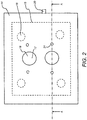
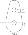
- Figure 2 presents a view of the base 14 from above and Figure 3 a view of the mould 12 from below.
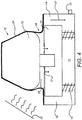
- Figures 1 , 4 and 5 are cross-sections of the arrangement seen along line A-A of Figures 2 and 3 .
- the base 14 comprises a support element 15 that is movable relative to the base.
- the support element 15 rests on biasing elements 16, for example coil spring supports or biasing cylinders.
- biasing elements 16 for example coil spring supports or biasing cylinders.
- the number of biasing elements can be chosen according to the application. In the shown examples four biasing elements 16 are provided. This is shown by the dashed circles in Figure 2 .
- the support element 15 has corresponding recesses, or bores, 18 for receiving the protruding elements 13 of the mould 12.
- the protruding elements 13 rest on the bottoms 17 of the respective two recesses of the support element but it shall be appreciated that the support can also be arranged otherwise.
- the two protruding elements 13 have been shown to have circular cross-sections, other shapes and numbers of co-operative elements are possible. It shall thus be appreciated that a different number of differently shaped co-operative elements can be provided to support and align the mould relative to the base.
- the forming tool 10 further comprises a vacuum generation arrangement.
- the base 14 comprises a chamber 19 providing a sealed volume within the base block.
- Generation of vacuum within the chamber or volume 19 in the base 14 can be provided in various manners. Vacuum can be generated within the volume 19 e.g. through connection 20 in any appropriate manner. Openings 21 between the upper surface of the base 14 and the inside volume of the base allow for suction to be generated (denoted by arrows at 21 of Figs. 4 and 5 ) such that vacuum is applied to upper material 24 placed on top of the mould 12 and the base 14.
- vacuum can be generated between the upper material placed on the mould and the base such that the upper material is drawn against the mould and the base.
- heating equipment 22 can be provided for application of heat to the upper material 24 during the forming process. After the forming the heat is removed, and the material is allowed to harden to the desired shape.
- the support element 15 can move downwards within the base block 14. At the same time the support element 15 is biased by the biasing elements 16 against the downwards movement.
- the forming tool 10 is in a first operational position, shown in Figure 4 .
- the support element 15 is in its uppermost position where a gap 25 is provided between the mould 12 and the upper surface of the base 14.
- Figure 4 illustrates the beginning of the upper forming operation.
- Upper material 24 has been placed on top of the mould and the base.
- the material can comprise any material that can be vacuum formed, for example, sheet of thermoplastic polyurethane (TPU), Ethylene Vinyl Acetate (EVA), textile-polymer composite microfibers or materials collectively known as artificial leather or "vegan leather” can be used.
- TPU thermoplastic polyurethane
- EVA Ethylene Vinyl Acetate
- textile-polymer composite microfibers textile-polymer composite microfibers or materials collectively known as artificial leather or "vegan leather” can be used.
- Such materials include e.g. materials where polymers are cross-linked.
- the vacuum can be applied such that the upper material enters the gap 25 between the mould and the upper surface of the base during the downward movement, at least to some extent.
- the downward movement of the mould 12 can be used to produce inward extending flange 26 of the upper material such that the material extends underneath the mould.
- the vacuum is arranged to be powerful enough such that the upper material becomes drawn underneath the mould and trapped between the mould and the upper surface of the base when the mould is in a second, lower operational position.
- the inward formed flange or "inlasting" 26 can then be used for bonding between the upper and the sole. An example of this will be explained in more detail with reference to examples shown in Figures 10A and B .
- the upper material is drawn towards the gap while the mould moves towards the upper surface of the base such that rather than producing an inlasting a sharp corner can be provided between the side and outlasted welt portion of the upper.
- the formed outlasting and welt is then used for bonding the upper with the sole.
- Figure 6 shows an example of such a welt 31 and sharp corner 39 between the welt portion and a side 32 of an upper.
- Figure 6 also shows an example how the welt can be used for bonding of the upper with a sole part 30.
- Figure 7 shows a sectioned perspective view of a forming apparatus according to another example.
- the main operational principle of the apparatus of Figure 7 corresponds to that of Figures 1 to 5 .
- the forming tool of Figure 7 is further configured to be better suited for bonding the sole to the upper during the vacuum forming operation, or immediately thereafter.
- a prefabricated sole part 30 shown in Figure 8 can be bonded to the upper by the operation of the apparatus of Figure 7 .
- the prefabricated sole part 30 can be received by a recess 28 on the top surface of the base 14, Figure 9 showing the sole part 30 of Figure 8 being placed on top of the recess 28.
- the prefabricated sole part 30 of Figure 8 can comprise pre-applied adhesive 41, for example dried hot-melt glue.
- the prefabricated sole part can also comprise an insole made of the same material as the upper.
- insole 44 of a sole component can comprise e.g. an EVA (Ethylene Vinyl Acetate) based material and a PVB (Polyvinyl Butyral) based outsole 45.
- EVA Ethylene Vinyl Acetate
- PVB Polyvinyl Butyral
- Figure 8 shows further apertures 42 provided for enabling the components 13 and 38 of the supporting structure of the tool to extend through the sole part 30.
- the supporting structures extend through the openings in the sole component, aiding in accurate positioning of the sole component.
- the supporting arrangement can be such that bushes or sleeves 38 protrude from the supporting element 15 through the skirt of the base so that the protruding elements 13 or "studs" of the mould 12 can be placed into the bushes 38.
- the bushes assist in correct positioning of the sole component on the base 14.
- the mould and the sole are now aligned by the studs and the bushes, and thus the mould can be accurately pressed on the sole component.
- studs that can be inserted into and come out of the bushes will allow removal of the mould and hardened shoe forming from the tool once the vacuum forming process has taken place.
- the studs can also provide a fixture/datum point for the next stage of the assembly process where the mould is connected onto a robotic arm to allow trimming to take place. Once trimming has been completed the mould can be retrieved from the forming.
- the two component support structure also provides possibility of a dual rate biasing system.
- second set of springs By placing second set of springs between the studs and the bushes it is possible to easily alter the rate of descend of the mould and/or create a dual descend - this may encourage a better undercut/return on the forming.
- second springs can be placed between the studs and the supporting element providing a sprung platform that require more force to descend than the supporting element. During the forming process the sprung platform will descend first and then lockout once it reaches predefined position, where after a second descend can take place as a result of the stronger spring rate of the second springs.
- the mould support shall provide as even a distribution of load as possible.
- a large support area between the mould and the supporting element is not appropriate as thus would leave a large hole in the sole.
- the studs can be arranged to spread the load as even as possible during descend whilst minimising the size of cut-outs required in the prefabricated sole component. Apertures such as round or oval holes required in the prefabricated sole component can be closed, e.g. plugged, at the final stages of the manufacturing process, after the components extending there through have been removed.
- Figure 7 shows further a forming collar 40 that can be pressed against the welt 31 as described above with reference to Figure 6 .
- the forming collar can have a desired pattern on the lower edge thereof such that this pattern is provided onto the welt material during bonding stage when pressed against the welt.
- Figure 6 shows an example of pattern 33 that can be produced on the welt 31 by the moulding pattern 34 of the collar 40.
- Figure 7 shows also a locking or holding arrangement 37 comprising a lockout latch 36 and a catch 35.
- the catch can be sprung activated.
- the latch is fixed to the supporting element 15 such that the latch moves with the supporting element and thus the mould 12.
- the holding arrangement can be used to hold the mould 12 in the second position or lower until the upper material has cooled down sufficiently and/or the bonding of the upper to the sole component is completed. After a period of time the latch can be released e.g. by the control system of the forming tool.
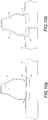
- Figure 10A shows an example of bonding of upper with a sole part 30 according to the herein described principles.
- the upper material has been drawn into the gap 25 to provide inlasting 26.
- the material extending into the gap between the mould 12 and the sole component 39 can be pressed as indicated by arrow 27 against the sole part 30 placed in the sole supporting area of the base 14.
- the materials can be glued and/or fused together by the pressure and/or heat. It is possible to directly cement the upper to the sole. It is also possible to use the "outflange" part provided by the upper material extending out of the gap for bonding the upper material to a welt of the sole. This may also be provided based on use of sole stitching, fusing (heat and/or pressure), adhesive and so on.
- Figure 10B shows another example where the sole part 30 on the base 14 is provided with upward extending corner part 31.
- the bonding can be provided between the upper material 24 and the corner part. This may also be provided based on corner stitching, fusing, adhesive, and so on.
- Figures 11A to 11D show sectioned views of further examples of joining the upper and the sole.
- adhesive 41 is provided on the upper surface of a welt portion 44 on the edge of a sole part 30.
- Corresponding welt portion 31 of the upper is pressed against the adhesive and the sole by collar 40.
- the collar 40 has a recess 45 that forms that forms a pattern of protruding formation 46 on the welt.
- the pattern formed on the welt 31 can have the appearance of stitching.
- the collar 40 has a protruding element 47 that forms 31 a recess 48 on the welt 31. Formations 46 and 48 can both be provided on the welt, and can e.g. alternate.
- the protruding element 46 can cause local pressure on the materials of the welt portions 31 and 44 and on the adhesive 41, thereby assisting in efficient local fusing of the material.
- the components can be welded or fused together without use of any adhesives. This can be advantageous e.g. when there is a desire to avoid industrial emissions that are possible with certain types of adhesives.
- Bonding of upper and sole materials can be provided based on techniques using heat and/or pressure.
- the pressure can be provided by vacuum sucking the component materials together.
- the fusing operation can be computer controlled. Appropriate temperature and/or pressure etc. parameters for different materials can be found by testing. For example, materials of appropriately dimensioned and shaped surface areas are fused together under appropriate temperatures and programmed vacuum pressures, over an appropriate period of time before the materials are cooled. Testing has shown that the bond strength achieved by fusing far exceeds footwear requirements, even if no adhesives are used.
- the non-adhesive welding concept can also be used e.g. to bond linings to the outsides.
- Figure 12 shows a flowchart for a process of manufacturing an article of footwear.
- a mould is supported relative to a base of a forming tool such that a gap is provided between at least a part of the mould and the base.
- Upper material is placed on the mould at 102 and drawn towards the mould and the gap at 104 by vacuum at the same time when the gap between the mould and the base reduces.
- the mould can be biased away from the base.
- the movement between the base and the mould can be caused by the vacuum drawing the upper material towards the base and overcoming the biasing force.
- a different bias can be applied in different parts of the mould to provide desired movement of the mould relative to the base. This can be done to accommodate the different desired shape of the upper and the mould at different locations and different suction forces caused by different surface areas at different locations to ensure appropriate movement of the mould.
- the bias applied to at least a part of the mould can be made adjustable. For example, differently sized and/or shaped moulds and/or uppers can require differently arranged biasing. The adjustment can be controlled by a control system, for example when adjustable biasing elements are used. Alternatively, the apparatus can be configured to enable easy manual change of spring components or the like.
- a sole part of a footwear can be placed on the base at 110 at the beginning of the manufacturing cycle.
- the placing can be provided e.g. by means of an automaton such as a robot.
- a gap is provided between the mould and the base where after upper material is placed on the mould, as above.
- the material can be brought into contact with the sole part at 113 by the vacuum and the relative movement between the mould and the base.
- the sole part can comprise a prefabricated sole comprising an adhesive component, the adhesive component being activated when pressed against the upper material and/or heated at 114.
- material on the sole part may fuse with the upper material. Additional pressing tools may also be used at this stage. If no adhesives are used, components can be welded or fused together using heart and/or pressure.
- the method can comprise providing a vacuum for sucking component materials together. Bonding can comprise fusing together materials of appropriately dimensioned and shaped surface areas under appropriate temperatures and programmed vacuum pressures, over an appropriate period of time before the materials are cooled. Other components can be bond in similar fashion, for example linings can be bonded by fusing to the outsides.
- the article of footwear can comprise an upper and therein bonded sole.
- the mould can be removed from the upper such that one of more supports extending through one or more apertures on the sole removed by pulling the mould from the upper though an ankle opening in the upper.
- This stage can be provided by an automated tool such as a robot.
- the cutting can be provided by a laser cutting tool.
- a relatively low powered laser for example a laser with about 20 kW nominal power, can be used.
- the formed upper material is moved relative to the laser cutting tool by a robot.
- Moving the object rather than the laser tool is a safety measure ensuring that the laser beam is pointed to the same direction rather than swings freely in the three dimensional work space.
- the robot 50 can comprise a gripping tool 54 arranged to appropriately grip the formed upper.
- the robot can be arranged to remove the mould from the formed upper.
- a tool can be provided that grips the mould and removes it from the upper.
- the robot can grip e.g. the protruding support elements, or the empty upper if the mould has already been removed, and move the upper relative to the laser beam 59 by the cutting tool 58 in appropriate manner.
- the robot can advantageously comprise a 7-axis robot.
- the upper material of the formed upper can be cut and trimmed to provide an upper with desired shapes, cuts and patterns.
- the final shape, eyelets and/or other openings such as vents or decorative holes, tongue, facing parts of the vamp, and decorative patterns can be provided by laser cutting.
- the robot 50 can be controlled by a controller 52.
- the controller 52 can be configured to control the operation of the various elements of the forming apparatus as described herein.
- the controller 52 can be connected to one of more other controllers to ensure cooperation between the various tools.
- FIG. 15A and B Schematic examples of this are illustrated by Figures 15A and B where different final products 57 (the outline of these shown by the stronger lines) are cut by laser beam 59 from a vacuum formed article 56 by the robot 50.
- Figures 15A and B also illustrate the possibility of attaching the cutting tool 58 to the robot.
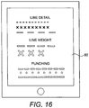
- Figure 16 illustrates an example of a graphical user interface 60 enabling the operator to customize various detail by selecting the desired patterns from the screen. Because of the flexibility and possibility of use one or only few different formed "bland" for a variety of final products a flexible manufacturing system can be provided.
- Figure 17 shows an example of a mould 70 that has been shaped to enable production of an upper with a tongue and facing parts of the vamp such that the facing parts overlap the tongue at the final article.
- This can be provided by a mould that has an over dimensioned frontal part 72 so that when the formed upper material is cut there is enough upper material to provide facing parts of the vamp overlapping the tongue.
- a dynamic mould or last is provided.
- Figure 18 shows an example of an adjustable mould 75 with exchangeable parts 76 and 77 by mean of which the shape of the mould can be altered.
- the mould can be adjusted according to a foot.
- differently sized and/or shaped lasts are provided by modular moulds. Differently sized and/or shaped parts altering the size and/or shape of the mould can be attached to a base mould part by e.g. magnets or other fast attachment means.
- deformable and/or extendable mould is provided based on hydraulic arrangements.
- the external shape of the mould be can be provided from rubber that is hard enough to resist the pressure from the vacuum forming while at the same time allowing extension of the external dimensions thereof by application of fluid, e.g. water or other suitable fluid for generating hydraulic pressure, underneath the rubber skin.
- fluid e.g. water or other suitable fluid for generating hydraulic pressure
- the manufacturing process can be controlled by one or more controller units.
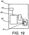
- Figure 19 shows an example of control apparatus for the control.
- the control apparatus 80 can be for example integrated with, coupled to and/or otherwise controlling the forming tool, the robot and cutting devices.
- the control apparatus comprises at least one memory 81, at least one data processing unit 82, 83 and an input/output interface 84. Via the interface the control apparatus can be coupled to the devices it is indented to control and/or a communication system for communication with other data processing apparatus, for example a manufacturing control system.
- the control apparatus can be configured to execute an appropriate software code to provide the control functions.
- Measurement data and other user specific data may have been be collected at a remote database such as in a server.
- the data may be associated with a user profile, and used e.g. for purchasing transactions.
- Data needed for the manufacture and control thereof can be communicated to the control apparatus of the forming apparatus from the remote location.
- the possibility of communicating manufacturing control instructions, measurement data and other data can be found useful for example in applications where footwear is manufactured in a plurality of remote locations, for example in local distribution centres and/or shoe shops.
- data can be communicated over an Internet Protocol (IP) based network between a remote server and local controllers.
- IP Internet Protocol
- data based on images by digital imaging apparatus is used in manufacture of footwear.
- digital cameras or smartphones can be used collecting the data.
- the data can comprise measurement data.
- decorations of the footwear can be based on images from imaging apparatus.
- a desired pattern may be produced on footwear based on image data.
- the pattern can be prefabricated, e.g. printed or mould, on the upper material and/or produced at the trimming stage.
- layered uppers can be produced.
- uppers consisting at least partially of two of more different material layers can be used.
- the layers can be of different thickness, density, material, colour and so on.
- the base, the moveable mould and other components of the tool can be manufactured from a variety of materials by a variety of techniques.
- the base and/or the mould can be made for example from plastic, aluminium or another metal allow, wood, hard rubber and so forth.
Landscapes
- Engineering & Computer Science (AREA)
- Mechanical Engineering (AREA)
- Footwear And Its Accessory, Manufacturing Method And Apparatuses (AREA)
Description
- The disclosure relates to manufacturing articles of footwear, and more particularly to methods and apparatuses such as tools and parts thereof for manufacturing articles of footwear. The disclosure further relates to footwear and components of footwear manufactured by the methods and apparatuses.
- An article of footwear can comprise e.g. a shoe, boot, sandal or the like or a component thereof. E.g. a shoe is typically manufactured from components known as an upper and a sole. An upper can be made from various materials such as leather, textiles and/or synthetic materials. A sole is typically made from a more hardwearing material. The upper and the sole can comprise layers of (different) materials.
- Various techniques are available for producing the shape of footwear. For example, upper material can be formed into a desired shape under heat and high pressure using a specific mould. The mould is commonly called a last in the field of shoemaking. The formed upper is attached to the sole, for example by means of gluing and/or stitching.
- Manufacture of footwear is a multistage process where upper and sole components are first formed in separate processes and then these components are bonded together. The various stages of manufacture are labour intensive operations. Shoemaking in its various stages can require skilled and well trained labour, this increasing the cost further. To achieve economies of scale shoes, boots, sandals and so on are typically mass produced in high volumes and long production runs. Any customisation of footwear is time consuming and expensive. For these reasons alone improvements in efficiency and/or flexibility in production of footwear would be desirable.
- Vacuum forming has been proposed as a possible technique for producing the uppers. In vacuum forming a sheet of material, typically synthetic material such as non-porous thermoplastic polyurethane (TPU) is drawn by vacuum around a mould while heat is applied on the material, thereby providing the shape of the upper. Examples of vacuum forming can be found from
US patent 7,178,267 andGB patents 1300931 1485891 DE1910094 A1 discloses a shoe gluing device using a folding rubber wall drawn by vacuum to press free edges of shaft material against shoe skeleton material placed around a last while the last is moved upwards. - However, vacuum forming techniques has difficulty in producing certain shapes and features of the upper in efficient and/or flexible manner. Also, the bonding between a vacuum formed upper and a sole can be problematic. This is partially caused by the difficulty to produce a lower edge of the upper having a shape that is suited for bonding with the sole, but there can also be, depending on the type of the footwear and the materials, other issues that have prevented vacuum forming from becoming widely adapted in manufacture of articles of footwear. There is a desire to provide more efficient and flexible methods, apparatuses and components for producing articles of footwear by means of vacuum assisted forming techniques. The invention relates to method of manufacturing an article of footwear as specified in appended
independent claim 1; and to an apparatus for producing an article of footwear as specified in appended independent claim 8. Preferred embodiments of the invention are disclosed in the dependent claims. - According to an aspect there is provided a method of manufacturing an article of footwear, comprising moveably supporting a mould relative to a base of a forming tool such that a gap is provided between at least a part of the mould and the base, placing upper material on the mould, and drawing the upper material towards the mould and the gap by vacuum at the same time when the gap between the mould and the base reduces.
- In accordance with another aspect there is provided an apparatus for producing an article of footwear, comprising a base, a mould movably supported relative to the base such that in a first position a gap is provided between at least a part of the mould and the base and in a second position the gap is reduced, and a vacuum arrangement configured to apply vacuum to upper material placed on the mould to draw the upper material towards the mould and the gap at the same time when the gap reduces.
- In accordance with a more specific aspect the supporting comprises a biasing arrangement biasing the mould away from the base. Different biasing in different parts of the mould may be provided. The biasing arrangement may comprise at least one spring and/or shock absorber. The biasing may also comprise multistage biasing. The biasing arrangement may be adjustable.
- The mould can be drawn towards the base by vacuum.
- The mould can be held in a position where the material forming an upper is in contact with a sole component. The mould can be released when the material has set.
- A sole part of a footwear is supported on the base and the upper material drawn towards the gap can be brought into contact with the sole part by the relative movement between the mould and the base. The upper material and sole part are then bond. The sole part may comprise a prefabricated sole comprising an adhesive component, the adhesive component being activated when pressed against the upper material and/or heated. The adhesive component may comprise hotmelt-type glue. Material on the sole part may be arranged to fuse with the upper material. The method may comprise fusing materials of two components together without use of an adhesive.
- The upper material may be treated by a laser cutting tool. A robot may be provided for moving the upper material in at least one stage of manufacture of the article of footwear. The robot may be configured to take a grip on the support arrangement. The robot may move the formed upper material relative to the laser cutting tool. The upper material may be cut to provide an upper with at least one of final shape, eyelets, tongue, facings, at least one vent opening, and a decorative pattern.
- The mould may be adjusted according to a foot.
- The article of footwear comprises an upper and therein bonded sole. The mould may be removably supported on the base by at least one support extending through respective aperture in the sole, and the mould can be removed from the upper though an ankle opening.
- At least one element supporting the mould can provide spring action between a protruding element and a corresponding bush.
- The mould can be arranged to provide a last with over dimensioned frontal part.
- A controller may also be provided, the controller being configured to control at least one of movement of the mould, application of vacuum, application of pressure on materials, heating of materials, cooling of materials, and bonding of materials of components together.
- Various exemplifying embodiments of the invention are described below with reference to the attached drawings. Steps and elements explained herein may be reordered, omitted, and combined to form different embodiments and any step indicated as performed may be caused to be performed by another device or module. In the drawings:
-
Figures 1 to 5 show an example of an apparatus and operation thereof for vacuum assisted forming of uppers; -
Figure 6 shows an upper and therein bonded sole; -
Figure 7 shows another example of an apparatus for vacuum assisted forming of uppers; -
Figure 8 shows an example of a prefabricated sole component; -
Figure 9 shows the sole component ofFigure 8 placed in the forming apparatus ofFigure 7 ; -
Figures 10A and 10B are examples of bonding an upper with a sole; -
Figures 11A to 11D are sectional views of examples of bonding upper and sole; -
Figures 12 and13 are flowcharts in accordance with certain embodiments; -
Figures 14 to 16 relate to the apparatus for trimming a formed upper; -
Figure 17 shows an example of a mould; -
Figure 18 shows an example of an adjustable mould; and -
Figure 19 shows an example of apparatus for controlling the manufacturing operations. - In the following certain detailed examples of use of vacuum forming for manufacture of at least a part of footwear in accordance with the herein described principles are described with reference to the appended Figures.
- A schematic example of a forming apparatus and operation thereof for forming uppers is shown in
Figures 1 to 5 . More particularly, a formingtool 10 ofFigure 1 comprises a mould, or last, 12 adapted to give an upper a desired shape. The forming tool further comprises a tool body, or base, 14 adapted to support the mould. The support is arranged such that relative movement between the mould and base can be provided. -
Figure 2 presents a view of the base 14 from above andFigure 3 a view of themould 12 from below.Figures 1 ,4 and5 are cross-sections of the arrangement seen along line A-A ofFigures 2 and3 . - The
base 14 comprises asupport element 15 that is movable relative to the base. Thesupport element 15 rests on biasingelements 16, for example coil spring supports or biasing cylinders. The number of biasing elements can be chosen according to the application. In the shown examples four biasingelements 16 are provided. This is shown by the dashed circles inFigure 2 . - Two protruding elements, or "studs", 13 are fixed underneath the
mould 12. Thesupport element 15 has corresponding recesses, or bores, 18 for receiving the protrudingelements 13 of themould 12. In the examples ofFigures 1 to 5 the protrudingelements 13 rest on thebottoms 17 of the respective two recesses of the support element but it shall be appreciated that the support can also be arranged otherwise. Further, although the two protrudingelements 13 have been shown to have circular cross-sections, other shapes and numbers of co-operative elements are possible. It shall thus be appreciated that a different number of differently shaped co-operative elements can be provided to support and align the mould relative to the base. - The forming
tool 10 further comprises a vacuum generation arrangement. In the example thebase 14 comprises achamber 19 providing a sealed volume within the base block. Generation of vacuum within the chamber orvolume 19 in the base 14 can be provided in various manners. Vacuum can be generated within thevolume 19 e.g. throughconnection 20 in any appropriate manner.Openings 21 between the upper surface of thebase 14 and the inside volume of the base allow for suction to be generated (denoted by arrows at 21 ofFigs. 4 and5 ) such that vacuum is applied toupper material 24 placed on top of themould 12 and thebase 14. - As generation of the vacuum within the chamber is not important for understanding the invention this will not be described any further detail. It is sufficient to note that vacuum can be generated between the upper material placed on the mould and the base such that the upper material is drawn against the mould and the base.
- If thermoforming materials are used,
heating equipment 22 can be provided for application of heat to theupper material 24 during the forming process. After the forming the heat is removed, and the material is allowed to harden to the desired shape. - As indicated by
arrow 27 thesupport element 15 can move downwards within thebase block 14. At the same time thesupport element 15 is biased by the biasingelements 16 against the downwards movement. When theprotruding elements 13 of themould 12 are placed into therecesses 18 of the supportingelement 15, and the mould is thus supported in therecesses 18, the formingtool 10 is in a first operational position, shown inFigure 4 . When the movement downwards has not yet started thesupport element 15 is in its uppermost position where agap 25 is provided between themould 12 and the upper surface of thebase 14. -
Figure 4 illustrates the beginning of the upper forming operation.Upper material 24 has been placed on top of the mould and the base. The material can comprise any material that can be vacuum formed, for example, sheet of thermoplastic polyurethane (TPU), Ethylene Vinyl Acetate (EVA), textile-polymer composite microfibers or materials collectively known as artificial leather or "vegan leather" can be used. Such materials include e.g. materials where polymers are cross-linked. - When vacuum is applied from the base 14 through the
openings 21 to the underneath of theupper material 24 the material is drawn towards themould 12 and the upper surface of the base. The upper material is also drawn towards thegap 25. At the same time the vacuum causes themould 12 to move downwards when the biasing force by the biasingelements 16 is arranged to be less than the drawing force by the vacuum. The cooperation of thegap 25, the vacuum throughopenings 21 and downward movement of themould 15 can be used to provide a sharp edge or even an inward bend of theupper material 24 at the low end of the upper that would not be possible with static moulds. - In some applications the vacuum can be applied such that the upper material enters the
gap 25 between the mould and the upper surface of the base during the downward movement, at least to some extent. Thus the downward movement of themould 12 can be used to produce inward extendingflange 26 of the upper material such that the material extends underneath the mould. This is shown in Figure of 5 where the vacuum is arranged to be powerful enough such that the upper material becomes drawn underneath the mould and trapped between the mould and the upper surface of the base when the mould is in a second, lower operational position. The inward formed flange or "inlasting" 26 can then be used for bonding between the upper and the sole. An example of this will be explained in more detail with reference to examples shown inFigures 10A and B . - In accordance with a possibility the upper material is drawn towards the gap while the mould moves towards the upper surface of the base such that rather than producing an inlasting a sharp corner can be provided between the side and outlasted welt portion of the upper. The formed outlasting and welt is then used for bonding the upper with the sole.
Figure 6 shows an example of such awelt 31 andsharp corner 39 between the welt portion and aside 32 of an upper.Figure 6 also shows an example how the welt can be used for bonding of the upper with asole part 30. -
Figure 7 shows a sectioned perspective view of a forming apparatus according to another example. The main operational principle of the apparatus ofFigure 7 corresponds to that ofFigures 1 to 5 . However, the forming tool ofFigure 7 is further configured to be better suited for bonding the sole to the upper during the vacuum forming operation, or immediately thereafter. More particularly, a prefabricatedsole part 30 shown inFigure 8 can be bonded to the upper by the operation of the apparatus ofFigure 7 . The prefabricatedsole part 30 can be received by arecess 28 on the top surface of thebase 14,Figure 9 showing thesole part 30 ofFigure 8 being placed on top of therecess 28. - The prefabricated
sole part 30 ofFigure 8 can comprise pre-applied adhesive 41, for example dried hot-melt glue. The prefabricated sole part can also comprise an insole made of the same material as the upper. For example,insole 44 of a sole component can comprise e.g. an EVA (Ethylene Vinyl Acetate) based material and a PVB (Polyvinyl Butyral) basedoutsole 45. -
Figure 8 showsfurther apertures 42 provided for enabling thecomponents sole part 30. The supporting structures extend through the openings in the sole component, aiding in accurate positioning of the sole component. - As shown by
Figure 7 , the supporting arrangement can be such that bushes orsleeves 38 protrude from the supportingelement 15 through the skirt of the base so that the protrudingelements 13 or "studs" of themould 12 can be placed into thebushes 38. The bushes assist in correct positioning of the sole component on thebase 14. The mould and the sole are now aligned by the studs and the bushes, and thus the mould can be accurately pressed on the sole component. - Use of "studs" that can be inserted into and come out of the bushes will allow removal of the mould and hardened shoe forming from the tool once the vacuum forming process has taken place. The studs can also provide a fixture/datum point for the next stage of the assembly process where the mould is connected onto a robotic arm to allow trimming to take place. Once trimming has been completed the mould can be retrieved from the forming.
- The two component support structure also provides possibility of a dual rate biasing system. By placing second set of springs between the studs and the bushes it is possible to easily alter the rate of descend of the mould and/or create a dual descend - this may encourage a better undercut/return on the forming. For example, second springs can be placed between the studs and the supporting element providing a sprung platform that require more force to descend than the supporting element. During the forming process the sprung platform will descend first and then lockout once it reaches predefined position, where after a second descend can take place as a result of the stronger spring rate of the second springs.
- The mould support shall provide as even a distribution of load as possible. On the other hand, a large support area between the mould and the supporting element is not appropriate as thus would leave a large hole in the sole. The studs can be arranged to spread the load as even as possible during descend whilst minimising the size of cut-outs required in the prefabricated sole component. Apertures such as round or oval holes required in the prefabricated sole component can be closed, e.g. plugged, at the final stages of the manufacturing process, after the components extending there through have been removed.
-
Figure 7 shows further a formingcollar 40 that can be pressed against thewelt 31 as described above with reference toFigure 6 . The forming collar can have a desired pattern on the lower edge thereof such that this pattern is provided onto the welt material during bonding stage when pressed against the welt.Figure 6 shows an example ofpattern 33 that can be produced on thewelt 31 by themoulding pattern 34 of thecollar 40. -
Figure 7 shows also a locking or holdingarrangement 37 comprising alockout latch 36 and acatch 35. The catch can be sprung activated. The latch is fixed to the supportingelement 15 such that the latch moves with the supporting element and thus themould 12. The holding arrangement can be used to hold themould 12 in the second position or lower until the upper material has cooled down sufficiently and/or the bonding of the upper to the sole component is completed. After a period of time the latch can be released e.g. by the control system of the forming tool. -
Figure 10A shows an example of bonding of upper with asole part 30 according to the herein described principles. The upper material has been drawn into thegap 25 to provideinlasting 26. The material extending into the gap between themould 12 and thesole component 39 can be pressed as indicated byarrow 27 against thesole part 30 placed in the sole supporting area of thebase 14. The materials can be glued and/or fused together by the pressure and/or heat. It is possible to directly cement the upper to the sole. It is also possible to use the "outflange" part provided by the upper material extending out of the gap for bonding the upper material to a welt of the sole. This may also be provided based on use of sole stitching, fusing (heat and/or pressure), adhesive and so on. -
Figure 10B shows another example where thesole part 30 on thebase 14 is provided with upward extendingcorner part 31. The bonding can be provided between theupper material 24 and the corner part. This may also be provided based on corner stitching, fusing, adhesive, and so on. -
Figures 11A to 11D show sectioned views of further examples of joining the upper and the sole. In these examples adhesive 41 is provided on the upper surface of awelt portion 44 on the edge of asole part 30.Corresponding welt portion 31 of the upper is pressed against the adhesive and the sole bycollar 40. - In the example of
Figures 11A and B thecollar 40 has arecess 45 that forms that forms a pattern of protrudingformation 46 on the welt. The pattern formed on thewelt 31 can have the appearance of stitching. In the example ofFigures 11C and D thecollar 40 has a protrudingelement 47 that forms 31 arecess 48 on thewelt 31.Formations element 46 can cause local pressure on the materials of thewelt portions - Use of mechanical pressure for the bonding can be advantageous e.g. if materials are used that could lose the formed shape if heated excessively at the bonding stage.
- The components can be welded or fused together without use of any adhesives. This can be advantageous e.g. when there is a desire to avoid industrial emissions that are possible with certain types of adhesives. Bonding of upper and sole materials can be provided based on techniques using heat and/or pressure. The pressure can be provided by vacuum sucking the component materials together. The fusing operation can be computer controlled. Appropriate temperature and/or pressure etc. parameters for different materials can be found by testing. For example, materials of appropriately dimensioned and shaped surface areas are fused together under appropriate temperatures and programmed vacuum pressures, over an appropriate period of time before the materials are cooled. Testing has shown that the bond strength achieved by fusing far exceeds footwear requirements, even if no adhesives are used.
- The non-adhesive welding concept can also be used e.g. to bond linings to the outsides.
-
Figure 12 shows a flowchart for a process of manufacturing an article of footwear. In the beginning of a manufacturing cycle at step 100 a mould is supported relative to a base of a forming tool such that a gap is provided between at least a part of the mould and the base. Upper material is placed on the mould at 102 and drawn towards the mould and the gap at 104 by vacuum at the same time when the gap between the mould and the base reduces. - The mould can be biased away from the base. The movement between the base and the mould can be caused by the vacuum drawing the upper material towards the base and overcoming the biasing force.
- A different bias can be applied in different parts of the mould to provide desired movement of the mould relative to the base. This can be done to accommodate the different desired shape of the upper and the mould at different locations and different suction forces caused by different surface areas at different locations to ensure appropriate movement of the mould. The bias applied to at least a part of the mould can be made adjustable. For example, differently sized and/or shaped moulds and/or uppers can require differently arranged biasing. The adjustment can be controlled by a control system, for example when adjustable biasing elements are used. Alternatively, the apparatus can be configured to enable easy manual change of spring components or the like.
- In accordance with an embodiment shown in
Figure 13 a sole part of a footwear can be placed on the base at 110 at the beginning of the manufacturing cycle. The placing can be provided e.g. by means of an automaton such as a robot. At 111 a gap is provided between the mould and the base where after upper material is placed on the mould, as above. When the upper material is drawn towards the gap at 112 the material can be brought into contact with the sole part at 113 by the vacuum and the relative movement between the mould and the base. - The sole part can comprise a prefabricated sole comprising an adhesive component, the adhesive component being activated when pressed against the upper material and/or heated at 114.
- At this stage material on the sole part may fuse with the upper material. Additional pressing tools may also be used at this stage. If no adhesives are used, components can be welded or fused together using heart and/or pressure. The method can comprise providing a vacuum for sucking component materials together. Bonding can comprise fusing together materials of appropriately dimensioned and shaped surface areas under appropriate temperatures and programmed vacuum pressures, over an appropriate period of time before the materials are cooled. Other components can be bond in similar fashion, for example linings can be bonded by fusing to the outsides.
- At the end of the forming cycle the article of footwear can comprise an upper and therein bonded sole. The mould can be removed from the upper such that one of more supports extending through one or more apertures on the sole removed by pulling the mould from the upper though an ankle opening in the upper. This stage can be provided by an automated tool such as a robot.
- After the forming excess upper material can be cut off. This can take place when the mould is still within the formed upper, or after the mould has been removed. Also, holes and/or decorative features can be cut to the upper material. The cutting can be provided by a laser cutting tool. For certain materials a relatively low powered laser, for example a laser with about 20 kW nominal power, can be used.
- According to a possibility the formed upper material is moved relative to the laser cutting tool by a robot. Moving the object rather than the laser tool is a safety measure ensuring that the laser beam is pointed to the same direction rather than swings freely in the three dimensional work space. However, it is possible to move the laser beams and/or both the laser beam and the upper.
- An example of use of a
robot 50 for the trimming stage of a formed upper 56 is shown inFigure 14 . Therobot 50 can comprise agripping tool 54 arranged to appropriately grip the formed upper. The robot can be arranged to remove the mould from the formed upper. A tool can be provided that grips the mould and removes it from the upper. The robot can grip e.g. the protruding support elements, or the empty upper if the mould has already been removed, and move the upper relative to thelaser beam 59 by the cuttingtool 58 in appropriate manner. The robot can advantageously comprise a 7-axis robot. - The upper material of the formed upper can be cut and trimmed to provide an upper with desired shapes, cuts and patterns. For example, the final shape, eyelets and/or other openings such as vents or decorative holes, tongue, facing parts of the vamp, and decorative patterns can be provided by laser cutting.
- The
robot 50 can be controlled by acontroller 52. Thecontroller 52 can be configured to control the operation of the various elements of the forming apparatus as described herein. Alternatively, thecontroller 52 can be connected to one of more other controllers to ensure cooperation between the various tools. - According to a possibility different styles and types of footwear can be cut from a single type of formed upper. For example, operator of the apparatus can select the final style from a plurality of possibilities. Schematic examples of this are illustrated by
Figures 15A and B where different final products 57 (the outline of these shown by the stronger lines) are cut bylaser beam 59 from a vacuum formedarticle 56 by therobot 50. -
Figures 15A and B also illustrate the possibility of attaching thecutting tool 58 to the robot. - The operator can select desired cuts from a user interface of the control system.
Figure 16 illustrates an example of agraphical user interface 60 enabling the operator to customize various detail by selecting the desired patterns from the screen. Because of the flexibility and possibility of use one or only few different formed "bland" for a variety of final products a flexible manufacturing system can be provided. -
Figure 17 shows an example of amould 70 that has been shaped to enable production of an upper with a tongue and facing parts of the vamp such that the facing parts overlap the tongue at the final article. This can be provided by a mould that has an over dimensionedfrontal part 72 so that when the formed upper material is cut there is enough upper material to provide facing parts of the vamp overlapping the tongue. - According to an aspect a dynamic mould or last is provided.
Figure 18 shows an example of anadjustable mould 75 withexchangeable parts - The manufacturing process can be controlled by one or more controller units.
Figure 19 shows an example of control apparatus for the control. Thecontrol apparatus 80 can be for example integrated with, coupled to and/or otherwise controlling the forming tool, the robot and cutting devices. For this purpose the control apparatus comprises at least onememory 81, at least onedata processing unit output interface 84. Via the interface the control apparatus can be coupled to the devices it is indented to control and/or a communication system for communication with other data processing apparatus, for example a manufacturing control system. The control apparatus can be configured to execute an appropriate software code to provide the control functions. - Measurement data and other user specific data may have been be collected at a remote database such as in a server. The data may be associated with a user profile, and used e.g. for purchasing transactions. Data needed for the manufacture and control thereof can be communicated to the control apparatus of the forming apparatus from the remote location. The possibility of communicating manufacturing control instructions, measurement data and other data can be found useful for example in applications where footwear is manufactured in a plurality of remote locations, for example in local distribution centres and/or shoe shops. For example, data can be communicated over an Internet Protocol (IP) based network between a remote server and local controllers.
- According to an aspect data based on images by digital imaging apparatus is used in manufacture of footwear. For example, digital cameras or smartphones can be used collecting the data. The data can comprise measurement data. Also, decorations of the footwear can be based on images from imaging apparatus. For example, a desired pattern may be produced on footwear based on image data. The pattern can be prefabricated, e.g. printed or mould, on the upper material and/or produced at the trimming stage.
- Further, layered uppers can be produced. For example, uppers consisting at least partially of two of more different material layers can be used. The layers can be of different thickness, density, material, colour and so on.
- While various aspects of the invention may be illustrated and described as block diagrams, flow charts, or using some other schematic pictorial representation, it is well understood that these blocks, apparatus, systems, techniques or methods described herein may be implemented in, as non-limiting examples, hardware, software, firmware, special purpose circuits or logic, general purpose hardware or controller or other computing devices, or some combination thereof.
- The base, the moveable mould and other components of the tool can be manufactured from a variety of materials by a variety of techniques. The base and/or the mould can be made for example from plastic, aluminium or another metal allow, wood, hard rubber and so forth.
- The foregoing description provides by way of exemplary and non-limiting examples a full and informative description of exemplary embodiments of the invention. However, various modifications and adaptations may become apparent to those skilled in the relevant arts in view of the foregoing description, when read in conjunction with the accompanying drawings and the appended claims. All such and similar modifications of the teachings of this invention will still fall within the scope of this invention as defined by the claims.
Claims (15)
- A method of manufacturing an article of footwear, comprising
moveably supporting a mould (12) relative to a base (14) of a forming tool such that a gap (25) is provided between at least a part of the mould and the base,
placing upper material (24) on the mould,
drawing the upper material (24) towards the mould (12) and the gap (25) by vacuum (21) at the same time when the gap between the mould and the base (14) reduces, characterized by
supporting a sole part (30) of the article of footwear on the base (14), bringing the upper material (24) drawn towards the gap (25) into contact with the sole part by the relative movement between the mould (12) and the base, and
bonding the upper material and the sole part. - A method as claimed in claim 1, comprising at least one of:biasing the mould (12) away from the base (14);biasing the mould (12) away from the base (14) such that different bias is applied in different parts of the mould;biasing the mould (12) away from the base (14) while adjusting the bias applied to at least a part of the mould;drawing the mould (12) towards the base (14) by vacuum; andholding the mould (12) in a position where the upper material (24) forming an upper is in contact with the sole part (30), and releasing the mould.
- A method as claimed in claim 1 or 2, wherein
the sole part (30) comprises a prefabricated sole part comprising an adhesive component (41), the method comprising activating the adhesive component when pressed against the upper material and/or heated. - A method as claimed in any preceding claim, comprising joining material on the sole part (30) of the article of the footwear with the upper material (24) using an adhesive.
- A method as claimed in any of claims 1 to 3, comprising fusing material of the sole part (30) of the article of the footwear with the upper material (24) without using an adhesive.
- A method as claimed in any preceding claim, further comprising cutting the upper material by a laser cutting tool (58), the cutting comprising moving by a robot (50) the formed upper material (56) relative to the laser cutting tool.
- A method as claimed in any preceding claim, wherein the article of footwear comprises an upper formed of the upper material and bonded to the sole part and the mould is removably supported on the base by at least one support (38) extending through respective aperture (42) in the sole part (30), the method comprising removing the mould (12) from the upper though an ankle opening.
- Apparatus (10) for producing an article of footwear, comprising:a base (14),a mould (12) movably supported relative to the base such that in a first position a gap (25) is provided between at least a part of the mould and the base and in a second position the gap is reduced,a vacuum arrangement (20, 21) configured to apply vacuum to upper material (24) placed on the mould to draw the upper material towards the mould (12) and the gap (25) at the same time when the gap is reduced, wherein the base (14) is configured to support a sole part (30) of the article of footwear, the apparatus being configured to bring the upper material (24) drawn towards the gap (25) in contact with the sole part and to cause bonding of the upper material and the sole part by pressing the sole part against the upper material drawn underneath the mould.
- An apparatus as claimed in claim 8, comprising a biasing arrangement (16) configured to bias the mould (12) away from the base (14).
- An apparatus as claimed in claim 9, wherein
the biasing arrangement configured to apply a different bias between the mould and the base in different parts of the mould; and/or
the biasing arrangement comprises at least one spring and/or shock absorber; and/or
the biasing arrangement is configured to provide multistage biasing; and/or
the biasing arrangement is adjustable. - An apparatus as claimed in any of claim 8 to 10, wherein the sole part comprises a prefabricated sole part comprising an adhesive component (41), the apparatus being configured to press the adhesive component of the prefabricated sole part against the upper material drawn underneath the mould or against a welt part of the prefabricated sole part.
- An apparatus as claimed in any of claims 8 to 11, comprising a support arrangement configured to extend between the mould (12) and a moveable support element (15) of the base (12) through one or more openings (42) of a sole part (30) placed between the mould and the base, wherein the support arrangement comprises at least two protruding elements (13) and corresponding bushes (38) receiving the protruding elements.
- An apparatus as claimed in claim 12, comprising at least one element providing spring action between a protruding element (13) and corresponding bush (38).
- An apparatus as claimed in any of claims 8 to 13, comprising a laser tool (58) for trimming the upper material and/or a robot (50) configured to move the upper material in at least one stage of manufacture of the article of footwear and/or take a grip on the support arrangement.
- An apparatus as claimed in any of claims 8 to 14, wherein the shape and/or size of the mould (75) is adjustable.
Applications Claiming Priority (2)
| Application Number | Priority Date | Filing Date | Title |
|---|---|---|---|
| GB1522319.1A GB2545469A (en) | 2015-12-17 | 2015-12-17 | Manufacturing articles of footwear |
| PCT/EP2016/081428 WO2017103107A1 (en) | 2015-12-17 | 2016-12-16 | Manufacturing articles of footwear |
Publications (2)
| Publication Number | Publication Date |
|---|---|
| EP3379966A1 EP3379966A1 (en) | 2018-10-03 |
| EP3379966B1 true EP3379966B1 (en) | 2020-05-27 |
Family
ID=55311169
Family Applications (1)
| Application Number | Title | Priority Date | Filing Date |
|---|---|---|---|
| EP16819052.8A Active EP3379966B1 (en) | 2015-12-17 | 2016-12-16 | Manufacturing articles of footwear |
Country Status (3)
| Country | Link |
|---|---|
| EP (1) | EP3379966B1 (en) |
| GB (1) | GB2545469A (en) |
| WO (1) | WO2017103107A1 (en) |
Cited By (1)
| Publication number | Priority date | Publication date | Assignee | Title |
|---|---|---|---|---|
| WO2022031449A1 (en) * | 2020-08-06 | 2022-02-10 | Dupont Safety & Construction, Inc. | Trimming of contoured polymeric panels |
Families Citing this family (1)
| Publication number | Priority date | Publication date | Assignee | Title |
|---|---|---|---|---|
| US12629898B2 (en) * | 2022-07-29 | 2026-05-19 | Stratasys, Inc. | Methods and systems for ensuring consistent tensioning of membrane in frame |
Family Cites Families (5)
| Publication number | Priority date | Publication date | Assignee | Title |
|---|---|---|---|---|
| DE1910094A1 (en) * | 1969-02-28 | 1970-09-10 | Bruno Romen | Method and device for glue pinching in shoe manufacture |
| IT1402066B1 (en) * | 2010-10-18 | 2013-08-28 | Sarong Spa | FORMING APPARATUS |
| US9585438B2 (en) * | 2013-02-22 | 2017-03-07 | Nike, Inc. | System and method for forming an article |
| US9278464B2 (en) * | 2013-08-27 | 2016-03-08 | Chaei Hsin Enterprise Co., Ltd. | Molding machine for making thermoplastic composites |
| WO2015060263A1 (en) * | 2013-10-22 | 2015-04-30 | 日立化成株式会社 | Vacuum forming method |
-
2015
- 2015-12-17 GB GB1522319.1A patent/GB2545469A/en not_active Withdrawn
-
2016
- 2016-12-16 EP EP16819052.8A patent/EP3379966B1/en active Active
- 2016-12-16 WO PCT/EP2016/081428 patent/WO2017103107A1/en not_active Ceased
Non-Patent Citations (1)
| Title |
|---|
| None * |
Cited By (2)
| Publication number | Priority date | Publication date | Assignee | Title |
|---|---|---|---|---|
| WO2022031449A1 (en) * | 2020-08-06 | 2022-02-10 | Dupont Safety & Construction, Inc. | Trimming of contoured polymeric panels |
| US12070894B2 (en) | 2020-08-06 | 2024-08-27 | Dupont Safety & Construction, Inc. | Trimming of contoured polymeric panels |
Also Published As
| Publication number | Publication date |
|---|---|
| GB2545469A (en) | 2017-06-21 |
| EP3379966A1 (en) | 2018-10-03 |
| GB201522319D0 (en) | 2016-02-03 |
| WO2017103107A1 (en) | 2017-06-22 |
Similar Documents
| Publication | Publication Date | Title |
|---|---|---|
| US20180000195A1 (en) | Thermoforming footwear method | |
| EP3113927B1 (en) | Method of vacuum forming a footwear upper | |
| US11219270B2 (en) | Dual-layered midsole | |
| CN102405002B (en) | Method of making footwear with grooves in the sole | |
| CN106723675B (en) | Automated manufacturing of shoe parts | |
| TWI527525B (en) | Sole plate assembly and method of making | |
| EP2079577B1 (en) | Method of producing footwear | |
| CN108143051B (en) | Method for manufacturing a fully formed upper | |
| EP2337467B1 (en) | Shoe with a flat formed shoe upper | |
| CN111698924A (en) | Direct-soled article of footwear with membrane | |
| EP2337675B1 (en) | Stock fit assembly fixture for shoe production | |
| EP3563708A1 (en) | Method of manufacturing a non-lasted skate boot shell | |
| WO2017103107A1 (en) | Manufacturing articles of footwear | |
| CN113329656B (en) | Method for manufacturing shoe sole | |
| TW201526817A (en) | Method for manufacturing shoes | |
| US4372525A (en) | Insole, apparatus for molding and method of making shoes | |
| US20180352899A1 (en) | Process for making a shoe and shoe thus made | |
| CN110338519A (en) | The manufacturing method and its manufacturing device of shoes part | |
| EP3578071B1 (en) | String guide module for article of footwear | |
| CN106239956B (en) | A kind of moulding process of integral shoes | |
| CN207186105U (en) | Have the vamp of polyurethane solid decorative patterns and its made shoes | |
| US20230189928A1 (en) | High-heeled shoe comprising a main body produced by a 3d printing process | |
| EP3750436A1 (en) | A method for realising a shoe and a shoe obtained with the method | |
| US326150A (en) | Method of attaching soles of | |
| KR102168667B1 (en) | shoes manufacturing method for easy customizing |
Legal Events
| Date | Code | Title | Description |
|---|---|---|---|
| STAA | Information on the status of an ep patent application or granted ep patent |
Free format text: STATUS: UNKNOWN |
|
| STAA | Information on the status of an ep patent application or granted ep patent |
Free format text: STATUS: THE INTERNATIONAL PUBLICATION HAS BEEN MADE |
|
| PUAI | Public reference made under article 153(3) epc to a published international application that has entered the european phase |
Free format text: ORIGINAL CODE: 0009012 |
|
| STAA | Information on the status of an ep patent application or granted ep patent |
Free format text: STATUS: REQUEST FOR EXAMINATION WAS MADE |
|
| 17P | Request for examination filed |
Effective date: 20180628 |
|
| AK | Designated contracting states |
Kind code of ref document: A1 Designated state(s): AL AT BE BG CH CY CZ DE DK EE ES FI FR GB GR HR HU IE IS IT LI LT LU LV MC MK MT NL NO PL PT RO RS SE SI SK SM TR |
|
| AX | Request for extension of the european patent |
Extension state: BA ME |
|
| STAA | Information on the status of an ep patent application or granted ep patent |
Free format text: STATUS: EXAMINATION IS IN PROGRESS |
|
| DAV | Request for validation of the european patent (deleted) | ||
| DAX | Request for extension of the european patent (deleted) | ||
| 17Q | First examination report despatched |
Effective date: 20190326 |
|
| GRAP | Despatch of communication of intention to grant a patent |
Free format text: ORIGINAL CODE: EPIDOSNIGR1 |
|
| STAA | Information on the status of an ep patent application or granted ep patent |
Free format text: STATUS: GRANT OF PATENT IS INTENDED |
|
| INTG | Intention to grant announced |
Effective date: 20200108 |
|
| GRAS | Grant fee paid |
Free format text: ORIGINAL CODE: EPIDOSNIGR3 |
|
| GRAA | (expected) grant |
Free format text: ORIGINAL CODE: 0009210 |
|
| STAA | Information on the status of an ep patent application or granted ep patent |
Free format text: STATUS: THE PATENT HAS BEEN GRANTED |
|
| AK | Designated contracting states |
Kind code of ref document: B1 Designated state(s): AL AT BE BG CH CY CZ DE DK EE ES FI FR GB GR HR HU IE IS IT LI LT LU LV MC MK MT NL NO PL PT RO RS SE SI SK SM TR |
|
| REG | Reference to a national code |
Ref country code: GB Ref legal event code: FG4D |
|
| REG | Reference to a national code |
Ref country code: CH Ref legal event code: EP |
|
| REG | Reference to a national code |
Ref country code: AT Ref legal event code: REF Ref document number: 1273598 Country of ref document: AT Kind code of ref document: T Effective date: 20200615 |
|
| REG | Reference to a national code |
Ref country code: DE Ref legal event code: R096 Ref document number: 602016037184 Country of ref document: DE |
|
| REG | Reference to a national code |
Ref country code: LT Ref legal event code: MG4D |
|
| PG25 | Lapsed in a contracting state [announced via postgrant information from national office to epo] |
Ref country code: LT Free format text: LAPSE BECAUSE OF FAILURE TO SUBMIT A TRANSLATION OF THE DESCRIPTION OR TO PAY THE FEE WITHIN THE PRESCRIBED TIME-LIMIT Effective date: 20200527 Ref country code: GR Free format text: LAPSE BECAUSE OF FAILURE TO SUBMIT A TRANSLATION OF THE DESCRIPTION OR TO PAY THE FEE WITHIN THE PRESCRIBED TIME-LIMIT Effective date: 20200828 Ref country code: NO Free format text: LAPSE BECAUSE OF FAILURE TO SUBMIT A TRANSLATION OF THE DESCRIPTION OR TO PAY THE FEE WITHIN THE PRESCRIBED TIME-LIMIT Effective date: 20200827 Ref country code: FI Free format text: LAPSE BECAUSE OF FAILURE TO SUBMIT A TRANSLATION OF THE DESCRIPTION OR TO PAY THE FEE WITHIN THE PRESCRIBED TIME-LIMIT Effective date: 20200527 Ref country code: PT Free format text: LAPSE BECAUSE OF FAILURE TO SUBMIT A TRANSLATION OF THE DESCRIPTION OR TO PAY THE FEE WITHIN THE PRESCRIBED TIME-LIMIT Effective date: 20200928 Ref country code: SE Free format text: LAPSE BECAUSE OF FAILURE TO SUBMIT A TRANSLATION OF THE DESCRIPTION OR TO PAY THE FEE WITHIN THE PRESCRIBED TIME-LIMIT Effective date: 20200527 Ref country code: IS Free format text: LAPSE BECAUSE OF FAILURE TO SUBMIT A TRANSLATION OF THE DESCRIPTION OR TO PAY THE FEE WITHIN THE PRESCRIBED TIME-LIMIT Effective date: 20200927 |
|
| REG | Reference to a national code |
Ref country code: NL Ref legal event code: MP Effective date: 20200527 |
|
| PG25 | Lapsed in a contracting state [announced via postgrant information from national office to epo] |
Ref country code: HR Free format text: LAPSE BECAUSE OF FAILURE TO SUBMIT A TRANSLATION OF THE DESCRIPTION OR TO PAY THE FEE WITHIN THE PRESCRIBED TIME-LIMIT Effective date: 20200527 Ref country code: RS Free format text: LAPSE BECAUSE OF FAILURE TO SUBMIT A TRANSLATION OF THE DESCRIPTION OR TO PAY THE FEE WITHIN THE PRESCRIBED TIME-LIMIT Effective date: 20200527 Ref country code: LV Free format text: LAPSE BECAUSE OF FAILURE TO SUBMIT A TRANSLATION OF THE DESCRIPTION OR TO PAY THE FEE WITHIN THE PRESCRIBED TIME-LIMIT Effective date: 20200527 Ref country code: BG Free format text: LAPSE BECAUSE OF FAILURE TO SUBMIT A TRANSLATION OF THE DESCRIPTION OR TO PAY THE FEE WITHIN THE PRESCRIBED TIME-LIMIT Effective date: 20200827 |
|
| REG | Reference to a national code |
Ref country code: AT Ref legal event code: MK05 Ref document number: 1273598 Country of ref document: AT Kind code of ref document: T Effective date: 20200527 |
|
| PG25 | Lapsed in a contracting state [announced via postgrant information from national office to epo] |
Ref country code: AL Free format text: LAPSE BECAUSE OF FAILURE TO SUBMIT A TRANSLATION OF THE DESCRIPTION OR TO PAY THE FEE WITHIN THE PRESCRIBED TIME-LIMIT Effective date: 20200527 Ref country code: NL Free format text: LAPSE BECAUSE OF FAILURE TO SUBMIT A TRANSLATION OF THE DESCRIPTION OR TO PAY THE FEE WITHIN THE PRESCRIBED TIME-LIMIT Effective date: 20200527 |
|
| PG25 | Lapsed in a contracting state [announced via postgrant information from national office to epo] |
Ref country code: ES Free format text: LAPSE BECAUSE OF FAILURE TO SUBMIT A TRANSLATION OF THE DESCRIPTION OR TO PAY THE FEE WITHIN THE PRESCRIBED TIME-LIMIT Effective date: 20200527 Ref country code: RO Free format text: LAPSE BECAUSE OF FAILURE TO SUBMIT A TRANSLATION OF THE DESCRIPTION OR TO PAY THE FEE WITHIN THE PRESCRIBED TIME-LIMIT Effective date: 20200527 Ref country code: CZ Free format text: LAPSE BECAUSE OF FAILURE TO SUBMIT A TRANSLATION OF THE DESCRIPTION OR TO PAY THE FEE WITHIN THE PRESCRIBED TIME-LIMIT Effective date: 20200527 Ref country code: IT Free format text: LAPSE BECAUSE OF FAILURE TO SUBMIT A TRANSLATION OF THE DESCRIPTION OR TO PAY THE FEE WITHIN THE PRESCRIBED TIME-LIMIT Effective date: 20200527 Ref country code: AT Free format text: LAPSE BECAUSE OF FAILURE TO SUBMIT A TRANSLATION OF THE DESCRIPTION OR TO PAY THE FEE WITHIN THE PRESCRIBED TIME-LIMIT Effective date: 20200527 Ref country code: DK Free format text: LAPSE BECAUSE OF FAILURE TO SUBMIT A TRANSLATION OF THE DESCRIPTION OR TO PAY THE FEE WITHIN THE PRESCRIBED TIME-LIMIT Effective date: 20200527 Ref country code: EE Free format text: LAPSE BECAUSE OF FAILURE TO SUBMIT A TRANSLATION OF THE DESCRIPTION OR TO PAY THE FEE WITHIN THE PRESCRIBED TIME-LIMIT Effective date: 20200527 Ref country code: SM Free format text: LAPSE BECAUSE OF FAILURE TO SUBMIT A TRANSLATION OF THE DESCRIPTION OR TO PAY THE FEE WITHIN THE PRESCRIBED TIME-LIMIT Effective date: 20200527 |
|
| PG25 | Lapsed in a contracting state [announced via postgrant information from national office to epo] |
Ref country code: SK Free format text: LAPSE BECAUSE OF FAILURE TO SUBMIT A TRANSLATION OF THE DESCRIPTION OR TO PAY THE FEE WITHIN THE PRESCRIBED TIME-LIMIT Effective date: 20200527 Ref country code: PL Free format text: LAPSE BECAUSE OF FAILURE TO SUBMIT A TRANSLATION OF THE DESCRIPTION OR TO PAY THE FEE WITHIN THE PRESCRIBED TIME-LIMIT Effective date: 20200527 |
|
| REG | Reference to a national code |
Ref country code: DE Ref legal event code: R097 Ref document number: 602016037184 Country of ref document: DE |
|
| PLBE | No opposition filed within time limit |
Free format text: ORIGINAL CODE: 0009261 |
|
| STAA | Information on the status of an ep patent application or granted ep patent |
Free format text: STATUS: NO OPPOSITION FILED WITHIN TIME LIMIT |
|
| 26N | No opposition filed |
Effective date: 20210302 |
|
| PG25 | Lapsed in a contracting state [announced via postgrant information from national office to epo] |
Ref country code: SI Free format text: LAPSE BECAUSE OF FAILURE TO SUBMIT A TRANSLATION OF THE DESCRIPTION OR TO PAY THE FEE WITHIN THE PRESCRIBED TIME-LIMIT Effective date: 20200527 |
|
| REG | Reference to a national code |
Ref country code: CH Ref legal event code: PL |
|
| PG25 | Lapsed in a contracting state [announced via postgrant information from national office to epo] |
Ref country code: MC Free format text: LAPSE BECAUSE OF FAILURE TO SUBMIT A TRANSLATION OF THE DESCRIPTION OR TO PAY THE FEE WITHIN THE PRESCRIBED TIME-LIMIT Effective date: 20200527 |
|
| REG | Reference to a national code |
Ref country code: BE Ref legal event code: MM Effective date: 20201231 |
|
| PG25 | Lapsed in a contracting state [announced via postgrant information from national office to epo] |
Ref country code: IE Free format text: LAPSE BECAUSE OF NON-PAYMENT OF DUE FEES Effective date: 20201216 Ref country code: FR Free format text: LAPSE BECAUSE OF NON-PAYMENT OF DUE FEES Effective date: 20201231 Ref country code: LU Free format text: LAPSE BECAUSE OF NON-PAYMENT OF DUE FEES Effective date: 20201216 |
|
| PG25 | Lapsed in a contracting state [announced via postgrant information from national office to epo] |
Ref country code: CH Free format text: LAPSE BECAUSE OF NON-PAYMENT OF DUE FEES Effective date: 20201231 Ref country code: LI Free format text: LAPSE BECAUSE OF NON-PAYMENT OF DUE FEES Effective date: 20201231 |
|
| PGFP | Annual fee paid to national office [announced via postgrant information from national office to epo] |
Ref country code: GB Payment date: 20211230 Year of fee payment: 6 |
|
| PGFP | Annual fee paid to national office [announced via postgrant information from national office to epo] |
Ref country code: DE Payment date: 20211230 Year of fee payment: 6 |
|
| PG25 | Lapsed in a contracting state [announced via postgrant information from national office to epo] |
Ref country code: TR Free format text: LAPSE BECAUSE OF FAILURE TO SUBMIT A TRANSLATION OF THE DESCRIPTION OR TO PAY THE FEE WITHIN THE PRESCRIBED TIME-LIMIT Effective date: 20200527 Ref country code: MT Free format text: LAPSE BECAUSE OF FAILURE TO SUBMIT A TRANSLATION OF THE DESCRIPTION OR TO PAY THE FEE WITHIN THE PRESCRIBED TIME-LIMIT Effective date: 20200527 Ref country code: CY Free format text: LAPSE BECAUSE OF FAILURE TO SUBMIT A TRANSLATION OF THE DESCRIPTION OR TO PAY THE FEE WITHIN THE PRESCRIBED TIME-LIMIT Effective date: 20200527 |
|
| PG25 | Lapsed in a contracting state [announced via postgrant information from national office to epo] |
Ref country code: MK Free format text: LAPSE BECAUSE OF FAILURE TO SUBMIT A TRANSLATION OF THE DESCRIPTION OR TO PAY THE FEE WITHIN THE PRESCRIBED TIME-LIMIT Effective date: 20200527 |
|
| REG | Reference to a national code |
Ref country code: GB Ref legal event code: 732E Free format text: REGISTERED BETWEEN 20220630 AND 20220706 |
|
| PG25 | Lapsed in a contracting state [announced via postgrant information from national office to epo] |
Ref country code: BE Free format text: LAPSE BECAUSE OF NON-PAYMENT OF DUE FEES Effective date: 20201231 |
|
| REG | Reference to a national code |
Ref country code: DE Ref legal event code: R119 Ref document number: 602016037184 Country of ref document: DE |
|
| GBPC | Gb: european patent ceased through non-payment of renewal fee |
Effective date: 20221216 |
|
| PG25 | Lapsed in a contracting state [announced via postgrant information from national office to epo] |
Ref country code: GB Free format text: LAPSE BECAUSE OF NON-PAYMENT OF DUE FEES Effective date: 20221216 Ref country code: DE Free format text: LAPSE BECAUSE OF NON-PAYMENT OF DUE FEES Effective date: 20230701 |