EP3379899B2 - Vehicle window glass with electrical connector soldered by lead-free solder - Google Patents
Vehicle window glass with electrical connector soldered by lead-free solder Download PDFInfo
- Publication number
- EP3379899B2 EP3379899B2 EP18163070.8A EP18163070A EP3379899B2 EP 3379899 B2 EP3379899 B2 EP 3379899B2 EP 18163070 A EP18163070 A EP 18163070A EP 3379899 B2 EP3379899 B2 EP 3379899B2
- Authority
- EP
- European Patent Office
- Prior art keywords
- layer
- metal plate
- plate element
- window glass
- vehicle window
- Prior art date
- Legal status (The legal status is an assumption and is not a legal conclusion. Google has not performed a legal analysis and makes no representation as to the accuracy of the status listed.)
- Active
Links
Images

Classifications
-
- H—ELECTRICITY
- H05—ELECTRIC TECHNIQUES NOT OTHERWISE PROVIDED FOR
- H05B—ELECTRIC HEATING; ELECTRIC LIGHT SOURCES NOT OTHERWISE PROVIDED FOR; CIRCUIT ARRANGEMENTS FOR ELECTRIC LIGHT SOURCES, IN GENERAL
- H05B3/00—Ohmic-resistance heating
- H05B3/84—Heating arrangements specially adapted for transparent or reflecting areas, e.g. for demisting or de-icing windows, mirrors or vehicle windshields
- H05B3/86—Heating arrangements specially adapted for transparent or reflecting areas, e.g. for demisting or de-icing windows, mirrors or vehicle windshields the heating conductors being embedded in the transparent or reflecting material
-
- B—PERFORMING OPERATIONS; TRANSPORTING
- B60—VEHICLES IN GENERAL
- B60J—WINDOWS, WINDSCREENS, NON-FIXED ROOFS, DOORS, OR SIMILAR DEVICES FOR VEHICLES; REMOVABLE EXTERNAL PROTECTIVE COVERINGS SPECIALLY ADAPTED FOR VEHICLES
- B60J1/00—Windows; Windscreens; Accessories therefor
-
- B—PERFORMING OPERATIONS; TRANSPORTING
- B32—LAYERED PRODUCTS
- B32B—LAYERED PRODUCTS, i.e. PRODUCTS BUILT-UP OF STRATA OF FLAT OR NON-FLAT, e.g. CELLULAR OR HONEYCOMB, FORM
- B32B15/00—Layered products comprising a layer of metal
- B32B15/02—Layer formed of wires, e.g. mesh
-
- B—PERFORMING OPERATIONS; TRANSPORTING
- B32—LAYERED PRODUCTS
- B32B—LAYERED PRODUCTS, i.e. PRODUCTS BUILT-UP OF STRATA OF FLAT OR NON-FLAT, e.g. CELLULAR OR HONEYCOMB, FORM
- B32B15/00—Layered products comprising a layer of metal
- B32B15/04—Layered products comprising a layer of metal comprising metal as the main or only constituent of a layer, which is next to another layer of the same or of a different material
-
- B—PERFORMING OPERATIONS; TRANSPORTING
- B32—LAYERED PRODUCTS
- B32B—LAYERED PRODUCTS, i.e. PRODUCTS BUILT-UP OF STRATA OF FLAT OR NON-FLAT, e.g. CELLULAR OR HONEYCOMB, FORM
- B32B17/00—Layered products essentially comprising sheet glass, or glass, slag, or like fibres
- B32B17/06—Layered products essentially comprising sheet glass, or glass, slag, or like fibres comprising glass as the main or only constituent of a layer, next to another layer of a specific material
-
- C—CHEMISTRY; METALLURGY
- C03—GLASS; MINERAL OR SLAG WOOL
- C03C—CHEMICAL COMPOSITION OF GLASSES, GLAZES OR VITREOUS ENAMELS; SURFACE TREATMENT OF GLASS; SURFACE TREATMENT OF FIBRES OR FILAMENTS MADE FROM GLASS, MINERALS OR SLAGS; JOINING GLASS TO GLASS OR OTHER MATERIALS
- C03C27/00—Joining pieces of glass to pieces of other inorganic material; Joining glass to glass other than by fusing
- C03C27/04—Joining glass to metal by means of an interlayer
- C03C27/042—Joining glass to metal by means of an interlayer consisting of a combination of materials selected from glass, glass-ceramic or ceramic material with metals, metal oxides or metal salts
- C03C27/046—Joining glass to metal by means of an interlayer consisting of a combination of materials selected from glass, glass-ceramic or ceramic material with metals, metal oxides or metal salts of metals, metal oxides or metal salts only
-
- C—CHEMISTRY; METALLURGY
- C22—METALLURGY; FERROUS OR NON-FERROUS ALLOYS; TREATMENT OF ALLOYS OR NON-FERROUS METALS
- C22C—ALLOYS
- C22C38/00—Ferrous alloys, e.g. steel alloys
- C22C38/08—Ferrous alloys, e.g. steel alloys containing nickel
-
- C—CHEMISTRY; METALLURGY
- C22—METALLURGY; FERROUS OR NON-FERROUS ALLOYS; TREATMENT OF ALLOYS OR NON-FERROUS METALS
- C22C—ALLOYS
- C22C38/00—Ferrous alloys, e.g. steel alloys
- C22C38/10—Ferrous alloys, e.g. steel alloys containing cobalt
- C22C38/105—Ferrous alloys, e.g. steel alloys containing cobalt containing Co and Ni
-
- H—ELECTRICITY
- H01—ELECTRIC ELEMENTS
- H01R—ELECTRICALLY-CONDUCTIVE CONNECTIONS; STRUCTURAL ASSOCIATIONS OF A PLURALITY OF MUTUALLY-INSULATED ELECTRICAL CONNECTING ELEMENTS; COUPLING DEVICES; CURRENT COLLECTORS
- H01R4/00—Electrically-conductive connections between two or more conductive members in direct contact, i.e. touching one another; Means for effecting or maintaining such contact; Electrically-conductive connections having two or more spaced connecting locations for conductors and using contact members penetrating insulation
- H01R4/02—Soldered or welded connections
-
- H—ELECTRICITY
- H05—ELECTRIC TECHNIQUES NOT OTHERWISE PROVIDED FOR
- H05B—ELECTRIC HEATING; ELECTRIC LIGHT SOURCES NOT OTHERWISE PROVIDED FOR; CIRCUIT ARRANGEMENTS FOR ELECTRIC LIGHT SOURCES, IN GENERAL
- H05B3/00—Ohmic-resistance heating
- H05B3/02—Details
- H05B3/06—Heater elements structurally combined with coupling elements or holders
-
- H—ELECTRICITY
- H05—ELECTRIC TECHNIQUES NOT OTHERWISE PROVIDED FOR
- H05B—ELECTRIC HEATING; ELECTRIC LIGHT SOURCES NOT OTHERWISE PROVIDED FOR; CIRCUIT ARRANGEMENTS FOR ELECTRIC LIGHT SOURCES, IN GENERAL
- H05B3/00—Ohmic-resistance heating
- H05B3/84—Heating arrangements specially adapted for transparent or reflecting areas, e.g. for demisting or de-icing windows, mirrors or vehicle windshields
-
- H—ELECTRICITY
- H01—ELECTRIC ELEMENTS
- H01R—ELECTRICALLY-CONDUCTIVE CONNECTIONS; STRUCTURAL ASSOCIATIONS OF A PLURALITY OF MUTUALLY-INSULATED ELECTRICAL CONNECTING ELEMENTS; COUPLING DEVICES; CURRENT COLLECTORS
- H01R2201/00—Connectors or connections adapted for particular applications
- H01R2201/26—Connectors or connections adapted for particular applications for vehicles
-
- H—ELECTRICITY
- H01—ELECTRIC ELEMENTS
- H01R—ELECTRICALLY-CONDUCTIVE CONNECTIONS; STRUCTURAL ASSOCIATIONS OF A PLURALITY OF MUTUALLY-INSULATED ELECTRICAL CONNECTING ELEMENTS; COUPLING DEVICES; CURRENT COLLECTORS
- H01R43/00—Apparatus or processes specially adapted for manufacturing, assembling, maintaining, or repairing of line connectors or current collectors or for joining electric conductors
- H01R43/02—Apparatus or processes specially adapted for manufacturing, assembling, maintaining, or repairing of line connectors or current collectors or for joining electric conductors for soldered or welded connections
- H01R43/0214—Resistance welding
-
- H—ELECTRICITY
- H05—ELECTRIC TECHNIQUES NOT OTHERWISE PROVIDED FOR
- H05B—ELECTRIC HEATING; ELECTRIC LIGHT SOURCES NOT OTHERWISE PROVIDED FOR; CIRCUIT ARRANGEMENTS FOR ELECTRIC LIGHT SOURCES, IN GENERAL
- H05B2203/00—Aspects relating to Ohmic resistive heating covered by group H05B3/00
- H05B2203/016—Heaters using particular connecting means
Definitions
- the invention relates to a vehicle window glass comprising an electrically conductive layer over the window glass, and an electrical connector soldered by a lead-free solder on the conductive layer.
- lead-containing solders In a vehicle window glass comprising an electrically conductive layer over the window glass and an electrical connectors soldered by a solder on the conductive layer, lead-containing solders have been used. However, the End of Life Vehicles Directive 2000/53/EC urges the use of lead-free solders instead of the lead-containing solders.
- US8816214 discloses a window glass comprising a glass substrate layer and an electrical connector made of a metal having thermal expansion coefficient near to that of the glass substrate layer.
- WO2007/110610 suggests that a thinner electrical connector, preferably an electrical connector having 0.1 mm to 0.5 mm thickness, can reduce the mechanical stress.
- US2016/0296569 proposes a discrete compensator plate between the connector and the conductive layer.
- CA2984056 discloses a pane with at least one electrical connection element, comprising a substrate, an electrically conductive structure on a region of the substrate, a bridge-shaped electric connection element, comprising a bridge region and at least two soldering feet, which are connected via a soldering compound to a region of the electrically conductive structure, and an electric connecting element attached to the connection element.
- connection element for contacting a surface-mounted conductive structure by means of soldering.
- the connection element is designed as a soldering foot or solder bridge with a connection piece wherein at least a region of the soldering foot or solder bridge to be connected to the conductive structure is fanned out and has at least two webs spaced apart by a slot.
- EP2683033 describes a glass plate having a feed terminal structure to be connected with a feeding portion of a glass plate with a conductive portion.
- a configuration of a solder connection surface of a terminal seat in a terminal structure having at least one terminal seat is disclosed.
- a connection with a high connection strength between a terminal and a conductive portion of a glass plate surface by using a Sn-based solder alloy containing Ag and Cu and having a high Young's modulus is described.
- US2015/264800 discloses a pane comprising a substrate and an electrical connection element containing at least a chromium containing steel.
- the connection element has a region which is crimped about a connecting cable and a soldering region connected to an electrically conductive structure by means of a lead-free solder.
- WO2016/096248 discloses a pane having at least one electrical connection element, comprising a flexible connection cable connected to the connection element, wherein the connection cable is provided with a stiffening element and the connection cable together with the stiffening element is surrounded a heat-shrink tube.
- the window glass disclosed in US8816214 is found to be still insufficient from the point of view of crack occurrences in the glass substrate layer. Thus, further improvement is required.
- WO2007/110610 suggests that an electrical connector having 0.1 mm to 0.5 mm thickness can reduce the mechanical stress, we found that such very thin electrical connectors are liable to the formation of hot spots in the connector during the soldering process using electric resistance heating of the connector. The generation of hot spots may result in residual stresses in the glass substrate layer, which cause cracks in the glass substrate layer.
- a vehicle window glass as set out in claim 1.
- a coloured ceramic band layer is sintered between the glass substrate layer and the conductive layer.
- the thickness of the solder layer may be between 0.1 mm and 0.3 mm.
- the solder layer may be made of a tin-based metal alloy comprising silver.
- the metal plate element may be, or may be comprised in, an electrical connector for connecting the electrically conductive layer to external electric wiring.
- Such electrical connector may comprise first and second said metal plate elements connected by a metal bridge portion, preferably formed integrally from a single piece of metal plate material.
- the thickness of the metal plate element is preferably at least 0.54 mm.
- the thickness is preferably not more than 0.6 mm.
- the iron alloy of the metal plate element is Invar 48.
- the surface of the metal plate element facing the solder layer is flat.
- the metal plate element may be coated with one or more metals selected from Ni, Cu and Ag, e.g. Ni, Cu and Ag layers in that order from the element.
- Another aspect is a method of making such a window glass, as set out in claim 12.
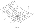
- a vehicle window glass 1 comprises a glass substrate layer 2 having an edge portion 21, an optional coloured ceramic band layer 6 sintered on a peripheral portion of the glass substrate layer 2, an electrically conductive layer 3, sintered on the glass substrate layer 2 and/or on the coloured ceramic band layer 6 and having a pair of busbars 31 and plural conductive wires 32 connected to the busbars 31, a lead-free solder layer 4 on the conductive layer 3 (preferably on a busbar 31 thereof), and a metal plate element 5 on the solder layer 4, to be connected to electric wiring either directly or via a metal bridge portion 51 connecting two such metal plate elements 5.
- the metal plate element constitutes or is comprised in an electrical connector.
- the connector may be made or formed from metal plate material, especially in a single piece.
- the connector may comprise one or at least one metal plate element 5, or may comprise two metal plate elements 5 and a metal bridge portion 51 connecting the two metal plate elements 5.
- a metal plate element 5 lies against the solder layer 4.
- the glass substrate layer 2 preferably has a curved shape, obtainable e.g. by a known bending process of a flat glass sheet.
- the glass substrate layer 2 may be a thermally tempered glass, a chemically tempered glass or a laminated glass.
- a soda-lime silicate glass defined by ISO16293-1 is used as a material of the glass substrate layer 2.
- the soda-lime silicate glass may comprise a colorant such as iron oxide and cobalt oxide, whereby to present a colour such as pale green, dark green, pale gray, dark gray, pale blue or dark blue.
- the coloured ceramic band layer 6 is of a colour ceramic composition preferably comprising an inorganic heat-resisting pigment and a glass frit that has lower softening temperature than that of the glass substrate layer 2.
- a peripheral band layer is well-known, and sometimes called a frit layer, ceramic band or paint band.
- the coloured ceramic band layer 6 is used to overlie an adhesion area between the vehicle window glass 1 and a body flange of a vehicle. It can improve weather resistance of the adhesion area and/or make it invisible by covering it, so that black colour is preferable as the hue of the coloured ceramic band layer 6.
- the thickness of the coloured ceramic band may be e.g. 5 ⁇ m to 25 ⁇ m, preferably 5 ⁇ m to 15 ⁇ m.
- the coloured ceramic band layer 6 can be obtained through the following process, for example. That is, a ceramic paste comprising the inorganic heat-resisting pigment, a glass frit and organic solvent is applied on the peripheral portion of the glass substrate layer 2 by a screen printing method or the like, and then heated, volatilizing the organic solvent. Subsequently, the composition comprising the inorganic heat-resisting pigment and glass frit is sintered on the glass substrate layer thereby forming the coloured ceramic band layer 6.
- the inorganic heat-resisting pigment is mixed to the colour ceramic to give a desired colour.
- the grain diameter of the inorganic heat-resisting pigment may be e.g. 0.1 ⁇ m to 10 ⁇ m, preferably 0.2 ⁇ m to 5 ⁇ m in median diameter (D50).
- D50 median diameter
- black pigments there can be mentioned copper-chromium complex oxide, iron-manganese complex oxide, cobalt-iron-manganese complex oxide, copper-chromium-manganese complex oxide, magnetite and the like.
- blue pigment there can be mentioned cobalt blue, chromium green, cobalt-zinc-nickel-titanium complex oxide, cobalt-aluminum-chromium complex oxide and the like.
- white pigment e.g. titanium white, zinc oxide and the like
- red pigment e.g. rouge and the like
- yellow pigment e.g. titanium yellow, titanium-barium-nickel complex oxide, titanium-antimony-nickel complex oxide, titanium-antimony-chromium complex oxide and the like
- other pigments in line with the skilled person's knowledge.
- the glass frit is fused through a heating process to form the coloured ceramic band layer 6.
- the glass frit usual ones can be used.
- the glass frit there can be mentioned borosilicate glass, boron-zinc-silicate glass, bismuth-based glass and the like.
- a softening temperature of the glass frit may be a lower temperature, for example 300-600°C, preferably 350-580°C, than a bending and forming temperature of the glass substrate layer 2.
- the grain diameter of the glass frit may be 0.1 ⁇ m to 10 ⁇ m, preferably 0.2 ⁇ m to 5 ⁇ m, further preferably 1 ⁇ m to 4 ⁇ m (determined as D50).
- the content of the glass material made of the glass frit may be 60 mass% to 80 mass%.
- the coloured ceramic band layer 6 can be also obtained through other methods besides the above-mentioned process. As an example of such other processes, there can be mentioned a digital printing process.
- the electrically conductive layer 3 preferably comprises silver metal (silver or silver alloy) and a glass frit which may be selected form those exemplified above.
- the thickness of the electrically conductive layer 3 may be e.g. 3 ⁇ m to 20 ⁇ m, preferably 5 ⁇ m to 15 ⁇ m, more preferably 12 ⁇ m to 17 ⁇ m.
- the electrically conductive layer 3 can be obtained through the following process. That is, a silver paste comprising the silver metal, the glass frit and an organic solvent is applied on the glass substrate layer 2, or on the coated and dried ceramic colour layer, by screen printing method or the like, and then is heated, volatilizing the organic solvent. Subsequently, the composition comprising the silver metal and the glass frit is sintered on the glass substrate layer 2 or coloured ceramic band 6 thereby forming the electrically conductive layer 3. As is well-known, the electrically conductive layer 3 can be used as a printed hot-wire such as a defogger and defroster, or as an antenna.
- the grain diameter of the silver metal may be e.g. 0.1 ⁇ m to 10 ⁇ m, preferably 0.2 ⁇ m to 7 ⁇ m (determined as D50).
- the content of the silver metal may be e.g. 65 mass% to 99 mass%, preferably 75 mass% to 98 mass%.
- the electrically conductive layer 3 can be also obtained through other methods besides the above-mentioned process. As an example of such other processes, there can be mentioned a digital printing process.
- the lead-free solder layer 4 made of a soldered lead-free solder connects the electrically conductive layer 3 with the electrical connector comprising metal plate elements 5.
- the lead-free solder is made of a tin-based metal alloy comprising silver.
- Sn-Ag based solder Sn-Ag-Cu based solder and the like.
- the content of Sn may be e.g. 95 mass% to 99 mass%, preferably 96 mass% to 98 mass%.
- the content of Ag may be e.g. 1 mass% to 5 mass%, preferably 2 mass% to 4 mass%.
- the content of Cu may be e.g. 0 mass% to 1.5 mass%, preferably 0.1 mass% to 1 mass%.
- the thickness of the lead-free solder layer 4 is desirably between 0.1 mm and 0.3 mm. In the case that the thickness is more than 0.3 mm, a difference of thermal expansion behaviour between the glass substrate 2 and the solder layer 4 may cause mechanical stress at an interface of the glass substrate layer 2 or the electrically conductive layer 3 during the soldering process, or while using the window glass 1 fitted in a vehicle. The mechanical stress may enhance a risk of permanent tensile stress in the glass substrate layer 2, resulting in crack generation in the glass substrate layer 2. On the other hand, in the case that the thickness is less than 0.1 mm, it may enhance a risk of a generation of hot spots at the solder layer during the soldering process. The generation of hot spots may result in the residual stress in the glass substrate layer 2, which causes cracking in the glass substrate layer 2.
- the thickness of the lead-free solder layer 4 may be preferably between 0.15 mm and 0.25 mm.
- the metal plate element 5 on the solder layer 4 is comprised in a connector to be directly connected to an electric wiring or to be connected to the electric wiring via metal bridge portion 51.
- the thickness of the metal plate element 5 on the solder layer 4 can influence the mechanical stress between the glass substrate layer 2 and the metal plate element 5.
- WO2007/110610 suggests that the thickness of the metal plate should be as thin as possible to reduce the mechanical stress. In this invention, however, the metal plate element 5 should be 0.52 mm to 0.65 mm thick.
- the thickness is too large, the mechanical stress can be too big to compensate, resulting in low yield of window glass 1 due to the occurrence of cracks in some window glasses 1.
- the thickness is too small, hot spots easily generate in the connector under soldering process with electric resistance heating of the connector, causing residual stress in the glass substrate layer 2. The residual stress turns into cracks in the glass substrate layer 2.
- Such a metal plate element (i.e. less than 0.5 mm thick) needs to be very carefully handled to preserve flatness of the surface facing the lead-free solder layer 4 of the terminal, and this difficulty leads to low productivity of the window glass 1.
- a metal plate element with a less flat surface can cause an inhomogeneous lead-free solder layer 4.
- the inhomogeneous lead-free solder layer 4 is liable to cause mechanical stress at the glass substrate layer side.
- the thickness of the metal plate element 5 on the solder layer 4 may be preferably 0.54 mm to 0.6 mm.
- the surface of the metal plate element 5 facing the solder layer 4 may desirably be flat, such as in particular having no protrusions or indentations, and/or not being bent or angled.
- a big difference in thermal expansion coefficient between the metal plate element 5 and the glass substrate layer 2 may affect the mechanical stress between the window glass and the electrical connector. From that point of view, the metal plate element 5 preferably has similar thermal expansion coefficient to the glass substrate layer 2.
- a thermal expansion coefficient of Invar 48 containing 48 mass% of nickel is roughly 9x10 -6 /degree C, which value is very close to one of a soda-lime silicate glass defined by ISO16293-1. Therefore, Invar 48 is the material of metal plate element 5.
- the electrical connector comprises at least one metal plate element 5, and may comprise two metal plate elements 5 and a metal bridge portion 51 connecting the two metal plate elements 5 as shown in Figure 1 .
- the metal plate element 5 that is soldered to the conductive layer and the metal bridge portion 51 are preferably made from one metal material, preferably formed through processing one flat plate metal piece. Further, the metal plate element 5 may be a part of a crimped-wire antenna. In such case, it goes without saying that metal plate element 5 plays a role as an electrical connector.
- the metal plate element 5 may be coated with at least one metal selected from a group consisting of Ni, Cu and Ag. Such coated metal plate element can improve wettability between the metal plate element 5 and melted lead-free solder. Further, the metal plate element 5 may be coated with a first Ni layer of 2 ⁇ m-5 ⁇ m thickness on the metal plate element 5, an intermediate Cu layer of 2 ⁇ m-5 ⁇ m thickness on the first Ni layer, and an external Ag layer of 5 ⁇ m-8 ⁇ m thickness on the Cu layer. The external Ag layer can promote the wettability and adhesion of the solder to the metal plate element.
- the intermediate Cu layer can protect a galvanic corrosion resulting from difference of ionization tendency between the Ag layer and "the first Ni layer or the metal plate element" and improve the electrical conductivity of Iron-based metal plate element 5.
- the first Ni layer may play a role as a primer to coating of the intermediate Cu layer. Not only the metal plate element 5 but also metal bridge portion 51 may be coated with same coating material(s) of the metal plate element 5.
- a producing method of the window glass 1 may comprise:
- a base test specimen was prepared.
- the specimen comprises a thermally tempered glass substrate layer 2 of 3 mm thickness and made of a soda-lime silicate glass defined by ISO16293-1, and an electrically conductive layer 3 comprising a busbar 31 fired from silver paste on the glass substrate layer 2.
- An electrical connector was also prepared, comprising two rectangular metal plate elements 5 (each having 6 x 4 mm 2 area), on each of which one side is welded to 45 mg to 50 mg of lead-free solder made of Sn (96.5 mass%)-Ag (3.0 mass%)-Cu (0.5 mass%), and with a metal bridge portion 51 connecting the two metal plate elements 5.
- the electrical connector was processed from a flat plate metal of 0.55 mm thickness made of Invar 48 coated with a first Ni layer on the metal, an intermediate Cu layer on the first Ni layer, and an external Ag layer on the intermediate Cu layer.
- the lead-free solder on the electrical connector was placed on the busbar 31 of the base test specimen, and heated by energizing between the two metal plate elements 5. By this step the lead-free solder was melted, and the electrical connector and the busbar 31 were soldered by the lead-free solder. In this experiment the soldered specimen was taken as the vehicle window glass 1.
- Example 1 The procedure of Example 1 was repeated with the exception that the electrical connector was processed from a flat plate metal of 0.4 mm thickness. Cracking was observed for 3 out of the 10 samples in this comparative example.
- Example 1 The procedure of Example 1 was repeated with the exception that the electrical connector was processed from a flat plate metal of 0.8 mm thickness. Cracking was observed for 3 out of the 10 samples in this comparative example.
Landscapes
- Chemical & Material Sciences (AREA)
- Engineering & Computer Science (AREA)
- Materials Engineering (AREA)
- Organic Chemistry (AREA)
- Mechanical Engineering (AREA)
- Metallurgy (AREA)
- Ceramic Engineering (AREA)
- Geochemistry & Mineralogy (AREA)
- Chemical Kinetics & Catalysis (AREA)
- General Chemical & Material Sciences (AREA)
- Life Sciences & Earth Sciences (AREA)
- Surface Treatment Of Glass (AREA)
- Connections Effected By Soldering, Adhesion, Or Permanent Deformation (AREA)
- Joining Of Glass To Other Materials (AREA)
- Manufacturing Of Printed Wiring (AREA)
- Other Surface Treatments For Metallic Materials (AREA)
- Manufacturing Of Electrical Connectors (AREA)
- Coupling Device And Connection With Printed Circuit (AREA)
- Electric Connection Of Electric Components To Printed Circuits (AREA)
- Glass Compositions (AREA)
- Surface Heating Bodies (AREA)
Description
- The invention relates to a vehicle window glass comprising an electrically conductive layer over the window glass, and an electrical connector soldered by a lead-free solder on the conductive layer.
- In a vehicle window glass comprising an electrically conductive layer over the window glass and an electrical connectors soldered by a solder on the conductive layer, lead-containing solders have been used. However, the End of Life Vehicles Directive 2000/53/EC urges the use of lead-free solders instead of the lead-containing solders.
- The use of lead-free solders has led to a difficulty in compensating mechanical stresses between the window glass and the electrical connectors, resulting in the occurrence of cracks in the window glass.
- In order to solve this problem,
US8816214 discloses a window glass comprising a glass substrate layer and an electrical connector made of a metal having thermal expansion coefficient near to that of the glass substrate layer. -
WO2007/110610 suggests that a thinner electrical connector, preferably an electrical connector having 0.1 mm to 0.5 mm thickness, can reduce the mechanical stress. -
US2016/0296569 proposes a discrete compensator plate between the connector and the conductive layer. -
CA2984056 discloses a pane with at least one electrical connection element, comprising a substrate, an electrically conductive structure on a region of the substrate, a bridge-shaped electric connection element, comprising a bridge region and at least two soldering feet, which are connected via a soldering compound to a region of the electrically conductive structure, and an electric connecting element attached to the connection element. -
DE202016008092 describes an electrical connection element for contacting a surface-mounted conductive structure by means of soldering. The connection element is designed as a soldering foot or solder bridge with a connection piece wherein at least a region of the soldering foot or solder bridge to be connected to the conductive structure is fanned out and has at least two webs spaced apart by a slot. -
EP2683033 describes a glass plate having a feed terminal structure to be connected with a feeding portion of a glass plate with a conductive portion. A configuration of a solder connection surface of a terminal seat in a terminal structure having at least one terminal seat is disclosed. A connection with a high connection strength between a terminal and a conductive portion of a glass plate surface by using a Sn-based solder alloy containing Ag and Cu and having a high Young's modulus is described. -
US2015/264800 discloses a pane comprising a substrate and an electrical connection element containing at least a chromium containing steel. The connection element has a region which is crimped about a connecting cable and a soldering region connected to an electrically conductive structure by means of a lead-free solder. -
WO2016/096248 discloses a pane having at least one electrical connection element, comprising a flexible connection cable connected to the connection element, wherein the connection cable is provided with a stiffening element and the connection cable together with the stiffening element is surrounded a heat-shrink tube. - The window glass disclosed in
US8816214 is found to be still insufficient from the point of view of crack occurrences in the glass substrate layer. Thus, further improvement is required. AlthoughWO2007/110610 suggests that an electrical connector having 0.1 mm to 0.5 mm thickness can reduce the mechanical stress, we found that such very thin electrical connectors are liable to the formation of hot spots in the connector during the soldering process using electric resistance heating of the connector. The generation of hot spots may result in residual stresses in the glass substrate layer, which cause cracks in the glass substrate layer. - It is an aim herein to provide new vehicle window glass comprising an electrically conductive layer over the window glass, and an electrical connector soldered by a lead-free solder on the conductive layer, especially taking account off the drawbacks mentioned above.
- According to one aspect of the present invention there is provided a vehicle window glass, as set out in claim 1.
- Other aspects and preferred aspects are set out in the claims and discussed below.
- Optionally a coloured ceramic band layer is sintered between the glass substrate layer and the conductive layer.
- The thickness of the solder layer may be between 0.1 mm and 0.3 mm. The solder layer may be made of a tin-based metal alloy comprising silver.
- The metal plate element may be, or may be comprised in, an electrical connector for connecting the electrically conductive layer to external electric wiring. Such electrical connector may comprise first and second said metal plate elements connected by a metal bridge portion, preferably formed integrally from a single piece of metal plate material.
- The thickness of the metal plate element is preferably at least 0.54 mm. The thickness is preferably not more than 0.6 mm.
- The iron alloy of the metal plate element is Invar 48.
- Preferably the surface of the metal plate element facing the solder layer is flat. The metal plate element may be coated with one or more metals selected from Ni, Cu and Ag, e.g. Ni, Cu and Ag layers in that order from the element.
- Another aspect is a method of making such a window glass, as set out in claim 12.
- We find that by using a window glass having the above structure, the mechanical stress between the window glass and an electrical connector including the metal plate element can be relaxed, and crack occurrence is decreased.
-
-
Fig. 1 is a schematic view showing main components for the present invention, and -
Fig.2 is a cross-sectional view at X-Y ofFig. 1 . - In the following description, for purposes of explanation and not limitation, specific details are set forth in order to provide an understanding of certain embodiments of the present invention. However, it will be apparent to those skilled in the art that the present invention may be practised in other embodiments that depart from these specific details. In other instances, detailed descriptions of well-known devices, processes, techniques, and methods are omitted so as not to obscure the description with unnecessary detail.
- We refer now more particularly to the accompanying drawings, in which like reference numerals indicate like parts/elements throughout the several views.
- For better understanding of the present invention, the present invention is described using figures.
Fig. 1 shows a schematic view of the main parts of a vehicle window glass embodying the present invention.Fig. 2 shows the X-Y cross-section ofFig. 1 . In accordance with typical embodiments of the present invention, a vehicle window glass 1 comprises aglass substrate layer 2 having anedge portion 21, an optional colouredceramic band layer 6 sintered on a peripheral portion of theglass substrate layer 2, an electricallyconductive layer 3, sintered on theglass substrate layer 2 and/or on the colouredceramic band layer 6 and having a pair ofbusbars 31 and pluralconductive wires 32 connected to thebusbars 31, a lead-free solder layer 4 on the conductive layer 3 (preferably on abusbar 31 thereof), and ametal plate element 5 on thesolder layer 4, to be connected to electric wiring either directly or via ametal bridge portion 51 connecting two suchmetal plate elements 5. The metal plate element constitutes or is comprised in an electrical connector. The connector may be made or formed from metal plate material, especially in a single piece. The connector may comprise one or at least onemetal plate element 5, or may comprise twometal plate elements 5 and ametal bridge portion 51 connecting the twometal plate elements 5. Ametal plate element 5 lies against thesolder layer 4. - The
glass substrate layer 2 preferably has a curved shape, obtainable e.g. by a known bending process of a flat glass sheet. Theglass substrate layer 2 may be a thermally tempered glass, a chemically tempered glass or a laminated glass. As a material of theglass substrate layer 2, a soda-lime silicate glass defined by ISO16293-1 is used. The soda-lime silicate glass may comprise a colorant such as iron oxide and cobalt oxide, whereby to present a colour such as pale green, dark green, pale gray, dark gray, pale blue or dark blue. - The coloured
ceramic band layer 6 is of a colour ceramic composition preferably comprising an inorganic heat-resisting pigment and a glass frit that has lower softening temperature than that of theglass substrate layer 2. Such a peripheral band layer is well-known, and sometimes called a frit layer, ceramic band or paint band. The colouredceramic band layer 6 is used to overlie an adhesion area between the vehicle window glass 1 and a body flange of a vehicle. It can improve weather resistance of the adhesion area and/or make it invisible by covering it, so that black colour is preferable as the hue of the colouredceramic band layer 6. The thickness of the coloured ceramic band may be e.g. 5 µm to 25 µm, preferably 5 µm to 15 µm. - The coloured
ceramic band layer 6 can be obtained through the following process, for example. That is, a ceramic paste comprising the inorganic heat-resisting pigment, a glass frit and organic solvent is applied on the peripheral portion of theglass substrate layer 2 by a screen printing method or the like, and then heated, volatilizing the organic solvent. Subsequently, the composition comprising the inorganic heat-resisting pigment and glass frit is sintered on the glass substrate layer thereby forming the colouredceramic band layer 6. - The inorganic heat-resisting pigment is mixed to the colour ceramic to give a desired colour. The grain diameter of the inorganic heat-resisting pigment may be e.g. 0.1µm to 10µm, preferably 0.2 µm to 5 µm in median diameter (D50). As the inorganic heat-resisting pigment, usual ones can be used. As examples of black pigments, there can be mentioned copper-chromium complex oxide, iron-manganese complex oxide, cobalt-iron-manganese complex oxide, copper-chromium-manganese complex oxide, magnetite and the like.
- As examples of blue pigment, there can be mentioned cobalt blue, chromium green, cobalt-zinc-nickel-titanium complex oxide, cobalt-aluminum-chromium complex oxide and the like.
- In addition to the above-mentioned, there can be used white pigment (e.g. titanium white, zinc oxide and the like), red pigment (e.g. rouge and the like), yellow pigment (e.g. titanium yellow, titanium-barium-nickel complex oxide, titanium-antimony-nickel complex oxide, titanium-antimony-chromium complex oxide and the like) and other pigments in line with the skilled person's knowledge.
- The glass frit is fused through a heating process to form the coloured
ceramic band layer 6. As the glass frit, usual ones can be used. As an example of the glass frit, there can be mentioned borosilicate glass, boron-zinc-silicate glass, bismuth-based glass and the like. A softening temperature of the glass frit may be a lower temperature, for example 300-600°C, preferably 350-580°C, than a bending and forming temperature of theglass substrate layer 2. The grain diameter of the glass frit may be 0.1 µm to 10 µm, preferably 0.2 µm to 5 µm, further preferably 1 µm to 4 µm (determined as D50). In the colouredceramic band 6, the content of the glass material made of the glass frit may be 60 mass% to 80 mass%. - The coloured
ceramic band layer 6 can be also obtained through other methods besides the above-mentioned process. As an example of such other processes, there can be mentioned a digital printing process. - The electrically
conductive layer 3, preferably sintered on theglass substrate layer 2 and/or on the colouredceramic band layer 6, has a pair ofbusbars 31 and pluralconductive wires 32 connected to thebusbars 31. The electricallyconductive layer 3 preferably comprises silver metal (silver or silver alloy) and a glass frit which may be selected form those exemplified above. The thickness of the electricallyconductive layer 3 may be e.g. 3 µm to 20 µm, preferably 5 µm to 15 µm, more preferably 12 µm to 17 µm. - The electrically
conductive layer 3 can be obtained through the following process. That is, a silver paste comprising the silver metal, the glass frit and an organic solvent is applied on theglass substrate layer 2, or on the coated and dried ceramic colour layer, by screen printing method or the like, and then is heated, volatilizing the organic solvent. Subsequently, the composition comprising the silver metal and the glass frit is sintered on theglass substrate layer 2 or colouredceramic band 6 thereby forming the electricallyconductive layer 3. As is well-known, the electricallyconductive layer 3 can be used as a printed hot-wire such as a defogger and defroster, or as an antenna. - The grain diameter of the silver metal may be e.g. 0.1 µm to 10 µm, preferably 0.2 µm to 7 µm (determined as D50). In the electrically
conductive layer 3, the content of the silver metal may be e.g. 65 mass% to 99 mass%, preferably 75 mass% to 98 mass%. - The electrically
conductive layer 3 can be also obtained through other methods besides the above-mentioned process. As an example of such other processes, there can be mentioned a digital printing process. - The lead-
free solder layer 4 made of a soldered lead-free solder connects the electricallyconductive layer 3 with the electrical connector comprisingmetal plate elements 5. The lead-free solder is made of a tin-based metal alloy comprising silver. As an example of such lead-free solder, there can be mentioned Sn-Ag based solder, Sn-Ag-Cu based solder and the like. The content of Sn may be e.g. 95 mass% to 99 mass%, preferably 96 mass% to 98 mass%. The content of Ag may be e.g. 1 mass% to 5 mass%, preferably 2 mass% to 4 mass%. The content of Cu may be e.g. 0 mass% to 1.5 mass%, preferably 0.1 mass% to 1 mass%. - The thickness of the lead-
free solder layer 4 is desirably between 0.1 mm and 0.3 mm. In the case that the thickness is more than 0.3 mm, a difference of thermal expansion behaviour between theglass substrate 2 and thesolder layer 4 may cause mechanical stress at an interface of theglass substrate layer 2 or the electricallyconductive layer 3 during the soldering process, or while using the window glass 1 fitted in a vehicle. The mechanical stress may enhance a risk of permanent tensile stress in theglass substrate layer 2, resulting in crack generation in theglass substrate layer 2. On the other hand, in the case that the thickness is less than 0.1 mm, it may enhance a risk of a generation of hot spots at the solder layer during the soldering process. The generation of hot spots may result in the residual stress in theglass substrate layer 2, which causes cracking in theglass substrate layer 2. - Considering all the factors, the thickness of the lead-
free solder layer 4 may be preferably between 0.15 mm and 0.25 mm. - The
metal plate element 5 on thesolder layer 4 is comprised in a connector to be directly connected to an electric wiring or to be connected to the electric wiring viametal bridge portion 51. The thickness of themetal plate element 5 on thesolder layer 4 can influence the mechanical stress between theglass substrate layer 2 and themetal plate element 5.WO2007/110610 suggests that the thickness of the metal plate should be as thin as possible to reduce the mechanical stress. In this invention, however, themetal plate element 5 should be 0.52 mm to 0.65 mm thick. - In the case that the thickness is too large, the mechanical stress can be too big to compensate, resulting in low yield of window glass 1 due to the occurrence of cracks in some window glasses 1. On the other hand, in the case that the thickness is too small, hot spots easily generate in the connector under soldering process with electric resistance heating of the connector, causing residual stress in the
glass substrate layer 2. The residual stress turns into cracks in theglass substrate layer 2. - Further, such a metal plate element (i.e. less than 0.5 mm thick) needs to be very carefully handled to preserve flatness of the surface facing the lead-
free solder layer 4 of the terminal, and this difficulty leads to low productivity of the window glass 1. A metal plate element with a less flat surface can cause an inhomogeneous lead-free solder layer 4. The inhomogeneous lead-free solder layer 4 is liable to cause mechanical stress at the glass substrate layer side. - Considering above mentioned factors, the thickness of the
metal plate element 5 on thesolder layer 4 may be preferably 0.54 mm to 0.6 mm. The surface of themetal plate element 5 facing thesolder layer 4 may desirably be flat, such as in particular having no protrusions or indentations, and/or not being bent or angled. - A big difference in thermal expansion coefficient between the
metal plate element 5 and theglass substrate layer 2 may affect the mechanical stress between the window glass and the electrical connector. From that point of view, themetal plate element 5 preferably has similar thermal expansion coefficient to theglass substrate layer 2. - A thermal expansion coefficient of Invar 48 containing 48 mass% of nickel is roughly 9x10⁻⁶ /degree C, which value is very close to one of a soda-lime silicate glass defined by ISO16293-1. Therefore, Invar 48 is the material of
metal plate element 5. - The electrical connector comprises at least one
metal plate element 5, and may comprise twometal plate elements 5 and ametal bridge portion 51 connecting the twometal plate elements 5 as shown inFigure 1 . Themetal plate element 5 that is soldered to the conductive layer and themetal bridge portion 51 are preferably made from one metal material, preferably formed through processing one flat plate metal piece. Further, themetal plate element 5 may be a part of a crimped-wire antenna. In such case, it goes without saying thatmetal plate element 5 plays a role as an electrical connector. - The
metal plate element 5 may be coated with at least one metal selected from a group consisting of Ni, Cu and Ag. Such coated metal plate element can improve wettability between themetal plate element 5 and melted lead-free solder. Further, themetal plate element 5 may be coated with a first Ni layer of 2µm-5µm thickness on themetal plate element 5, an intermediate Cu layer of 2µm-5µm thickness on the first Ni layer, and an external Ag layer of 5µm-8µm thickness on the Cu layer. The external Ag layer can promote the wettability and adhesion of the solder to the metal plate element. The intermediate Cu layer can protect a galvanic corrosion resulting from difference of ionization tendency between the Ag layer and "the first Ni layer or the metal plate element" and improve the electrical conductivity of Iron-basedmetal plate element 5. The first Ni layer may play a role as a primer to coating of the intermediate Cu layer. Not only themetal plate element 5 but alsometal bridge portion 51 may be coated with same coating material(s) of themetal plate element 5. - A producing method of the window glass 1 may comprise:
- a step of preparing the
glass substrate layer 2 having the electricallyconductive layer 3 over theglass substrate layer 2 and optional colouredceramic band layer 6 between theglass substrate layer 2 and theconductive layer 3; - a step of preparing the electrical connector comprising at least one
metal plate element 5 whose surface is welded by lead-free solder; - a step of placing the lead-free solder on the
conductive layer 3, and - a step of energizing to heat the electrical connector to melt the lead-free solder - this step corresponds to a soldering process with electric resistance heating.
- A base test specimen was prepared. The specimen comprises a thermally tempered
glass substrate layer 2 of 3 mm thickness and made of a soda-lime silicate glass defined by ISO16293-1, and an electricallyconductive layer 3 comprising abusbar 31 fired from silver paste on theglass substrate layer 2. An electrical connector was also prepared, comprising two rectangular metal plate elements 5 (each having 6 x 4 mm2 area), on each of which one side is welded to 45 mg to 50 mg of lead-free solder made of Sn (96.5 mass%)-Ag (3.0 mass%)-Cu (0.5 mass%), and with ametal bridge portion 51 connecting the twometal plate elements 5. The electrical connector was processed from a flat plate metal of 0.55 mm thickness made of Invar 48 coated with a first Ni layer on the metal, an intermediate Cu layer on the first Ni layer, and an external Ag layer on the intermediate Cu layer. - The lead-free solder on the electrical connector was placed on the
busbar 31 of the base test specimen, and heated by energizing between the twometal plate elements 5. By this step the lead-free solder was melted, and the electrical connector and thebusbar 31 were soldered by the lead-free solder. In this experiment the soldered specimen was taken as the vehicle window glass 1. - The following heat cycle tests were conducted for ten samples made in accordance with Example 1.
- (1) 20 times repeat of alternate cycling from -40°C to +80°C over 12 hours.
- (2) Holding each sample at -40°C for 4 hours and at +80°C for 4 hours, with 80% controlled humidity at positive temperatures and uncontrolled humidity at negative temperatures.
- The procedure of Example 1 was repeated with the exception that the electrical connector was processed from a flat plate metal of 0.4 mm thickness. Cracking was observed for 3 out of the 10 samples in this comparative example.
- The procedure of Example 1 was repeated with the exception that the electrical connector was processed from a flat plate metal of 0.8 mm thickness. Cracking was observed for 3 out of the 10 samples in this comparative example.
Claims (12)
- A vehicle window glass, comprisinga glass substrate layer (2);an electrically conductive layer (3) forming a conductive pattern over the glass substrate layer;a lead-free solder layer (4) on the conductive layer (3), anda metal plate element (5) on the solder layer (4), characterised in thatthe metal plate element (5) comprises iron alloy and has a thickness from 0.52 mm to 0.65 mm;the solder layer (4) is made of a tin-based metal alloy comprising silver;the iron alloy of the metal plate element (5) is Invar 48; andthe glass substrate layer (2) is a soda-lime silicate glass defined by ISO 16293-1.
- A vehicle window glass according to claim 1 comprising a coloured ceramic band layer (6) between the glass substrate layer (2) and the conductive layer (3).
- A vehicle window glass according to claim 1 or 2, wherein the thickness of the solder layer (4) is between 0.1 mm and 0.3 mm.
- A vehicle window glass according to any one of the preceding claims wherein the metal plate element (5) is comprised in an electrical connector for connecting the electrically conductive layer to external electric wiring.
- A vehicle window glass according to claim 4 in which the electrical connector comprises first and second said metal plate elements (5) connected by a metal bridge portion (51).
- A vehicle window glass according to claim 5 in which the first and second metal plate elements (5) and the metal bridge portion (51) are formed integrally from a single piece of metal plate material.
- A vehicle window glass according to any one of the preceding claims wherein the thickness of the metal plate element (5) is from 0.54 mm to 0.6 mm.
- A vehicle window glass according to any one of the preceding claims wherein a surface of the metal plate element (5) facing the solder layer (4) is flat.
- A vehicle window glass according to any one of claims 1 to 8 wherein a surface of the metal plate element (5) facing the solder layer (4) has no protrusions or indentations and is not bent or angled.
- A vehicle window glass according to any one of the preceding claims wherein the metal plate element (5) is coated with one or more metals selected from Ni, Cu and Ag.
- A vehicle window glass according to claim 10 wherein the metal plate element (5) is coated with a Ni layer of 2 µm - 5 µm thickness on the metal plate element, a Cu layer of 2 µm - 5 µm thickness on the Ni layer and an Ag layer of 5 µm - 8 µm thickness on the Cu layer.
- A method of making a vehicle window glass according to any one of claims 1 to 11, comprisingpreparing the glass substrate layer (2) having the electrically conductive layer (3) on the glass substrate layer;preparing an electrical connector comprising said at least one metal plate element (5) with a surface to be soldered;placing lead-free solder on the conductive layer, andenergizing to heat the electrical connector by electric resistance heating and thereby melt the lead-free solder between the conductive layer and said surface of the metal plate element (5).
Applications Claiming Priority (1)
| Application Number | Priority Date | Filing Date | Title |
|---|---|---|---|
| GBGB1704525.3A GB201704525D0 (en) | 2017-03-22 | 2017-03-22 | Vehicle glass window with electrical connector soldered by lead-free solder |
Publications (3)
| Publication Number | Publication Date |
|---|---|
| EP3379899A1 EP3379899A1 (en) | 2018-09-26 |
| EP3379899B1 EP3379899B1 (en) | 2020-10-28 |
| EP3379899B2 true EP3379899B2 (en) | 2025-04-09 |
Family
ID=58688378
Family Applications (1)
| Application Number | Title | Priority Date | Filing Date |
|---|---|---|---|
| EP18163070.8A Active EP3379899B2 (en) | 2017-03-22 | 2018-03-21 | Vehicle window glass with electrical connector soldered by lead-free solder |
Country Status (6)
| Country | Link |
|---|---|
| US (3) | US11659631B2 (en) |
| EP (1) | EP3379899B2 (en) |
| JP (1) | JP7037047B2 (en) |
| CN (1) | CN108621754B (en) |
| ES (1) | ES2834067T3 (en) |
| GB (1) | GB201704525D0 (en) |
Families Citing this family (7)
| Publication number | Priority date | Publication date | Assignee | Title |
|---|---|---|---|---|
| GB201704525D0 (en) * | 2017-03-22 | 2017-05-03 | Central Glass Co Ltd | Vehicle glass window with electrical connector soldered by lead-free solder |
| GB201804624D0 (en) * | 2018-03-22 | 2018-05-09 | Central Glass Co Ltd | Method of producing a vehicle glass assembly |
| US20230303433A1 (en) * | 2020-08-06 | 2023-09-28 | Carlex Glass America, Llc | Method of attaching a connector to a glazing |
| WO2022081453A1 (en) * | 2020-10-12 | 2022-04-21 | Carlex Glass America, Llc | Method of attaching a connector to a glass substrate and a glass product |
| FR3117106B1 (en) * | 2020-12-07 | 2023-08-25 | Saint Gobain | Process for obtaining glazing provided with an enamel coating and electroconductive patterns |
| CN116762239A (en) | 2021-02-01 | 2023-09-15 | Agc株式会社 | Window glass for vehicles with metal terminals |
| US11773011B1 (en) * | 2022-07-08 | 2023-10-03 | Agc Automotive Americas Co. | Glass assembly including a conductive feature and method of manufacturing thereof |
Citations (8)
| Publication number | Priority date | Publication date | Assignee | Title |
|---|---|---|---|---|
| GB1163224A (en) † | 1966-09-13 | 1969-09-04 | Saint Gobain | Electrical connectors for sheets of glass having electrically conductive strips on one surface thereof |
| WO2007110610A1 (en) † | 2006-03-24 | 2007-10-04 | Pilkington Group Limited | Electrical connector |
| DE102006017675A1 (en) † | 2006-04-12 | 2007-10-18 | Pilkington Automotive Deutschland Gmbh | Glass pane with electrical functional element with soldered connection leads and method for making electrical connections |
| WO2011107342A1 (en) † | 2010-03-02 | 2011-09-09 | Saint-Gobain Glass France | Disk with an electrical connection element |
| WO2012152543A1 (en) † | 2011-05-10 | 2012-11-15 | Saint-Gobain Glass France | Disk having an electric connecting element |
| WO2014040774A1 (en) † | 2012-09-14 | 2014-03-20 | Saint-Gobain Glass France | Pane having an electrical connection element |
| CA2884777A1 (en) † | 2012-09-14 | 2014-03-20 | Saint-Gobain Glass France | Pane with an electrical connection element |
| WO2014079595A1 (en) † | 2012-11-21 | 2014-05-30 | Saint-Gobain Glass France | Disk having an electric connecting element and compensator plates |
Family Cites Families (14)
| Publication number | Priority date | Publication date | Assignee | Title |
|---|---|---|---|---|
| ATE415644T1 (en) * | 2000-05-04 | 2008-12-15 | Schott Donnelly Llc | METHOD FOR PRODUCING AN ELECTROCHROMIC PANEL |
| GB0302230D0 (en) | 2003-01-30 | 2003-03-05 | Pilkington Plc | Vehicular glazing panel |
| US20070224842A1 (en) * | 2004-11-12 | 2007-09-27 | Agc Automotive Americas R&D, Inc. | Electrical Connector For A Window Pane Of A Vehicle |
| GB0605883D0 (en) | 2006-03-24 | 2006-05-03 | Pilkington Plc | Electrical connector |
| EP2408260A1 (en) * | 2010-07-13 | 2012-01-18 | Saint-Gobain Glass France | Glass pane with electric connection element |
| JPWO2012118202A1 (en) | 2011-03-02 | 2014-07-07 | セントラル硝子株式会社 | Terminal structure for glass plate with conductive part and glass plate article using the same |
| DE202011100906U1 (en) | 2011-05-03 | 2011-06-09 | FEW Fahrzeugelektrikwerk GmbH & Co. KG, 04442 | Electrical connection element |
| ES2621224T3 (en) * | 2012-11-21 | 2017-07-03 | Saint-Gobain Glass France | Panel with electrical connection element and joint core |
| ITMI20131467A1 (en) | 2013-09-06 | 2015-03-07 | Sofar Spa | USE OF A COMPOSITION INCLUDING MICRO-ORGANISMS TO INCREASE THE INTESTINAL PRODUCTION OF BUTIRRIC ACID, FOLIC ACID OR NIACINE ACID AND / OR TO REDUCE THE INTESTINAL PRODUCTION OF SUCCINIC ACID |
| PL3235340T3 (en) | 2014-12-16 | 2020-11-30 | Saint-Gobain Glass France | Pane with an electrical connection element and a flexible connection cable |
| CA2984056C (en) * | 2015-05-05 | 2020-03-24 | Saint-Gobain Glass France | Pane with electrical connection element and connecting element attached thereto |
| JP6612066B2 (en) | 2015-06-19 | 2019-11-27 | 日本板硝子株式会社 | Glass plate module |
| DE202016008092U1 (en) | 2016-12-28 | 2017-03-03 | Few Fahrzeugelektrikwerk Gmbh & Co. Kg | Electrical connection element |
| GB201704525D0 (en) * | 2017-03-22 | 2017-05-03 | Central Glass Co Ltd | Vehicle glass window with electrical connector soldered by lead-free solder |
-
2017
- 2017-03-22 GB GBGB1704525.3A patent/GB201704525D0/en not_active Ceased
-
2018
- 2018-03-06 JP JP2018039468A patent/JP7037047B2/en active Active
- 2018-03-20 US US15/926,502 patent/US11659631B2/en active Active
- 2018-03-21 EP EP18163070.8A patent/EP3379899B2/en active Active
- 2018-03-21 ES ES18163070T patent/ES2834067T3/en active Active
- 2018-03-22 CN CN201810238987.9A patent/CN108621754B/en active Active
-
2023
- 2023-04-19 US US18/136,510 patent/US12144071B2/en active Active
-
2024
- 2024-09-27 US US18/899,822 patent/US20250024562A1/en active Pending
Patent Citations (10)
| Publication number | Priority date | Publication date | Assignee | Title |
|---|---|---|---|---|
| GB1163224A (en) † | 1966-09-13 | 1969-09-04 | Saint Gobain | Electrical connectors for sheets of glass having electrically conductive strips on one surface thereof |
| WO2007110610A1 (en) † | 2006-03-24 | 2007-10-04 | Pilkington Group Limited | Electrical connector |
| DE102006017675A1 (en) † | 2006-04-12 | 2007-10-18 | Pilkington Automotive Deutschland Gmbh | Glass pane with electrical functional element with soldered connection leads and method for making electrical connections |
| WO2011107342A1 (en) † | 2010-03-02 | 2011-09-09 | Saint-Gobain Glass France | Disk with an electrical connection element |
| WO2011107341A1 (en) † | 2010-03-02 | 2011-09-09 | Saint-Gobain Glass France | Disk with an electrical connection element |
| WO2012152543A1 (en) † | 2011-05-10 | 2012-11-15 | Saint-Gobain Glass France | Disk having an electric connecting element |
| WO2014040774A1 (en) † | 2012-09-14 | 2014-03-20 | Saint-Gobain Glass France | Pane having an electrical connection element |
| CA2884777A1 (en) † | 2012-09-14 | 2014-03-20 | Saint-Gobain Glass France | Pane with an electrical connection element |
| WO2014040773A1 (en) † | 2012-09-14 | 2014-03-20 | Saint-Gobain Glass France | Pane having an electrical connection element |
| WO2014079595A1 (en) † | 2012-11-21 | 2014-05-30 | Saint-Gobain Glass France | Disk having an electric connecting element and compensator plates |
Non-Patent Citations (1)
| Title |
|---|
| ANONYMOUS: "Stainless- Steel EN Standards for Stainless Steel CR Sheet", WILSONS LTD., 18 July 2019 (2019-07-18), pages 1 - 3, XP055833522 † |
Also Published As
| Publication number | Publication date |
|---|---|
| JP7037047B2 (en) | 2022-03-16 |
| US11659631B2 (en) | 2023-05-23 |
| JP2018159128A (en) | 2018-10-11 |
| GB201704525D0 (en) | 2017-05-03 |
| EP3379899B1 (en) | 2020-10-28 |
| US20250024562A1 (en) | 2025-01-16 |
| US20180279419A1 (en) | 2018-09-27 |
| ES2834067T3 (en) | 2021-06-16 |
| CN108621754B (en) | 2023-04-14 |
| US12144071B2 (en) | 2024-11-12 |
| CN108621754A (en) | 2018-10-09 |
| US20230254947A1 (en) | 2023-08-10 |
| EP3379899A1 (en) | 2018-09-26 |
Similar Documents
| Publication | Publication Date | Title |
|---|---|---|
| EP3379899B2 (en) | Vehicle window glass with electrical connector soldered by lead-free solder | |
| US20070224842A1 (en) | Electrical Connector For A Window Pane Of A Vehicle | |
| KR20140032973A (en) | Windowpane for vehicles and method for producing same | |
| JP2008218399A (en) | Electrical connector for window pane of vehicle | |
| US20190174582A1 (en) | Glazing equipped with an electrically conductive device with improved soldering zones | |
| US10700408B2 (en) | Pane with electrical connection element and connecting element attached thereto | |
| EP3768465B1 (en) | Method of producing a vehicle glass assembly | |
| US10512169B2 (en) | Glazing equipped with an electrically conductive device possessing an improved resistance to temperature cycling tests | |
| JP2012091216A (en) | Lead-free solder alloy and glass article using the same | |
| EP3848148A1 (en) | Vehicle window glass assembly | |
| EP3768464B1 (en) | Method of producing a vehicle glass assembly | |
| EP3335279B1 (en) | Electrical connector |
Legal Events
| Date | Code | Title | Description |
|---|---|---|---|
| PUAI | Public reference made under article 153(3) epc to a published international application that has entered the european phase |
Free format text: ORIGINAL CODE: 0009012 |
|
| STAA | Information on the status of an ep patent application or granted ep patent |
Free format text: STATUS: REQUEST FOR EXAMINATION WAS MADE |
|
| 17P | Request for examination filed |
Effective date: 20180406 |
|
| AK | Designated contracting states |
Kind code of ref document: A1 Designated state(s): AL AT BE BG CH CY CZ DE DK EE ES FI FR GB GR HR HU IE IS IT LI LT LU LV MC MK MT NL NO PL PT RO RS SE SI SK SM TR |
|
| AX | Request for extension of the european patent |
Extension state: BA ME |
|
| STAA | Information on the status of an ep patent application or granted ep patent |
Free format text: STATUS: EXAMINATION IS IN PROGRESS |
|
| 17Q | First examination report despatched |
Effective date: 20200226 |
|
| GRAP | Despatch of communication of intention to grant a patent |
Free format text: ORIGINAL CODE: EPIDOSNIGR1 |
|
| STAA | Information on the status of an ep patent application or granted ep patent |
Free format text: STATUS: GRANT OF PATENT IS INTENDED |
|
| INTG | Intention to grant announced |
Effective date: 20200519 |
|
| RIN1 | Information on inventor provided before grant (corrected) |
Inventor name: FARREYROL, OLIVIER |
|
| GRAS | Grant fee paid |
Free format text: ORIGINAL CODE: EPIDOSNIGR3 |
|
| GRAA | (expected) grant |
Free format text: ORIGINAL CODE: 0009210 |
|
| STAA | Information on the status of an ep patent application or granted ep patent |
Free format text: STATUS: THE PATENT HAS BEEN GRANTED |
|
| AK | Designated contracting states |
Kind code of ref document: B1 Designated state(s): AL AT BE BG CH CY CZ DE DK EE ES FI FR GB GR HR HU IE IS IT LI LT LU LV MC MK MT NL NO PL PT RO RS SE SI SK SM TR |
|
| REG | Reference to a national code |
Ref country code: GB Ref legal event code: FG4D |
|
| REG | Reference to a national code |
Ref country code: CH Ref legal event code: EP |
|
| REG | Reference to a national code |
Ref country code: AT Ref legal event code: REF Ref document number: 1329567 Country of ref document: AT Kind code of ref document: T Effective date: 20201115 |
|
| REG | Reference to a national code |
Ref country code: DE Ref legal event code: R096 Ref document number: 602018009036 Country of ref document: DE |
|
| REG | Reference to a national code |
Ref country code: IE Ref legal event code: FG4D |
|
| REG | Reference to a national code |
Ref country code: AT Ref legal event code: MK05 Ref document number: 1329567 Country of ref document: AT Kind code of ref document: T Effective date: 20201028 |
|
| REG | Reference to a national code |
Ref country code: NL Ref legal event code: MP Effective date: 20201028 |
|
| PG25 | Lapsed in a contracting state [announced via postgrant information from national office to epo] |
Ref country code: GR Free format text: LAPSE BECAUSE OF FAILURE TO SUBMIT A TRANSLATION OF THE DESCRIPTION OR TO PAY THE FEE WITHIN THE PRESCRIBED TIME-LIMIT Effective date: 20210129 Ref country code: NO Free format text: LAPSE BECAUSE OF FAILURE TO SUBMIT A TRANSLATION OF THE DESCRIPTION OR TO PAY THE FEE WITHIN THE PRESCRIBED TIME-LIMIT Effective date: 20210128 Ref country code: RS Free format text: LAPSE BECAUSE OF FAILURE TO SUBMIT A TRANSLATION OF THE DESCRIPTION OR TO PAY THE FEE WITHIN THE PRESCRIBED TIME-LIMIT Effective date: 20201028 Ref country code: PT Free format text: LAPSE BECAUSE OF FAILURE TO SUBMIT A TRANSLATION OF THE DESCRIPTION OR TO PAY THE FEE WITHIN THE PRESCRIBED TIME-LIMIT Effective date: 20210301 Ref country code: FI Free format text: LAPSE BECAUSE OF FAILURE TO SUBMIT A TRANSLATION OF THE DESCRIPTION OR TO PAY THE FEE WITHIN THE PRESCRIBED TIME-LIMIT Effective date: 20201028 |
|
| REG | Reference to a national code |
Ref country code: LT Ref legal event code: MG4D |
|
| PG25 | Lapsed in a contracting state [announced via postgrant information from national office to epo] |
Ref country code: SE Free format text: LAPSE BECAUSE OF FAILURE TO SUBMIT A TRANSLATION OF THE DESCRIPTION OR TO PAY THE FEE WITHIN THE PRESCRIBED TIME-LIMIT Effective date: 20201028 Ref country code: PL Free format text: LAPSE BECAUSE OF FAILURE TO SUBMIT A TRANSLATION OF THE DESCRIPTION OR TO PAY THE FEE WITHIN THE PRESCRIBED TIME-LIMIT Effective date: 20201028 Ref country code: IS Free format text: LAPSE BECAUSE OF FAILURE TO SUBMIT A TRANSLATION OF THE DESCRIPTION OR TO PAY THE FEE WITHIN THE PRESCRIBED TIME-LIMIT Effective date: 20210228 Ref country code: LV Free format text: LAPSE BECAUSE OF FAILURE TO SUBMIT A TRANSLATION OF THE DESCRIPTION OR TO PAY THE FEE WITHIN THE PRESCRIBED TIME-LIMIT Effective date: 20201028 Ref country code: BG Free format text: LAPSE BECAUSE OF FAILURE TO SUBMIT A TRANSLATION OF THE DESCRIPTION OR TO PAY THE FEE WITHIN THE PRESCRIBED TIME-LIMIT Effective date: 20210128 Ref country code: AT Free format text: LAPSE BECAUSE OF FAILURE TO SUBMIT A TRANSLATION OF THE DESCRIPTION OR TO PAY THE FEE WITHIN THE PRESCRIBED TIME-LIMIT Effective date: 20201028 |
|
| REG | Reference to a national code |
Ref country code: ES Ref legal event code: FG2A Ref document number: 2834067 Country of ref document: ES Kind code of ref document: T3 Effective date: 20210616 |
|
| PG25 | Lapsed in a contracting state [announced via postgrant information from national office to epo] |
Ref country code: HR Free format text: LAPSE BECAUSE OF FAILURE TO SUBMIT A TRANSLATION OF THE DESCRIPTION OR TO PAY THE FEE WITHIN THE PRESCRIBED TIME-LIMIT Effective date: 20201028 Ref country code: NL Free format text: LAPSE BECAUSE OF FAILURE TO SUBMIT A TRANSLATION OF THE DESCRIPTION OR TO PAY THE FEE WITHIN THE PRESCRIBED TIME-LIMIT Effective date: 20201028 |
|
| REG | Reference to a national code |
Ref country code: DE Ref legal event code: R026 Ref document number: 602018009036 Country of ref document: DE |
|
| PG25 | Lapsed in a contracting state [announced via postgrant information from national office to epo] |
Ref country code: CZ Free format text: LAPSE BECAUSE OF FAILURE TO SUBMIT A TRANSLATION OF THE DESCRIPTION OR TO PAY THE FEE WITHIN THE PRESCRIBED TIME-LIMIT Effective date: 20201028 Ref country code: EE Free format text: LAPSE BECAUSE OF FAILURE TO SUBMIT A TRANSLATION OF THE DESCRIPTION OR TO PAY THE FEE WITHIN THE PRESCRIBED TIME-LIMIT Effective date: 20201028 Ref country code: SM Free format text: LAPSE BECAUSE OF FAILURE TO SUBMIT A TRANSLATION OF THE DESCRIPTION OR TO PAY THE FEE WITHIN THE PRESCRIBED TIME-LIMIT Effective date: 20201028 Ref country code: LT Free format text: LAPSE BECAUSE OF FAILURE TO SUBMIT A TRANSLATION OF THE DESCRIPTION OR TO PAY THE FEE WITHIN THE PRESCRIBED TIME-LIMIT Effective date: 20201028 Ref country code: RO Free format text: LAPSE BECAUSE OF FAILURE TO SUBMIT A TRANSLATION OF THE DESCRIPTION OR TO PAY THE FEE WITHIN THE PRESCRIBED TIME-LIMIT Effective date: 20201028 Ref country code: SK Free format text: LAPSE BECAUSE OF FAILURE TO SUBMIT A TRANSLATION OF THE DESCRIPTION OR TO PAY THE FEE WITHIN THE PRESCRIBED TIME-LIMIT Effective date: 20201028 |
|
| PLBI | Opposition filed |
Free format text: ORIGINAL CODE: 0009260 |
|
| PLAX | Notice of opposition and request to file observation + time limit sent |
Free format text: ORIGINAL CODE: EPIDOSNOBS2 |
|
| PG25 | Lapsed in a contracting state [announced via postgrant information from national office to epo] |
Ref country code: DK Free format text: LAPSE BECAUSE OF FAILURE TO SUBMIT A TRANSLATION OF THE DESCRIPTION OR TO PAY THE FEE WITHIN THE PRESCRIBED TIME-LIMIT Effective date: 20201028 |
|
| 26 | Opposition filed |
Opponent name: SAINT-GOBAIN GLASS FRANCE Effective date: 20210728 Opponent name: AGC GLASS EUROPE Effective date: 20210727 |
|
| PG25 | Lapsed in a contracting state [announced via postgrant information from national office to epo] |
Ref country code: AL Free format text: LAPSE BECAUSE OF FAILURE TO SUBMIT A TRANSLATION OF THE DESCRIPTION OR TO PAY THE FEE WITHIN THE PRESCRIBED TIME-LIMIT Effective date: 20201028 Ref country code: MC Free format text: LAPSE BECAUSE OF FAILURE TO SUBMIT A TRANSLATION OF THE DESCRIPTION OR TO PAY THE FEE WITHIN THE PRESCRIBED TIME-LIMIT Effective date: 20201028 Ref country code: IT Free format text: LAPSE BECAUSE OF FAILURE TO SUBMIT A TRANSLATION OF THE DESCRIPTION OR TO PAY THE FEE WITHIN THE PRESCRIBED TIME-LIMIT Effective date: 20201028 |
|
| REG | Reference to a national code |
Ref country code: CH Ref legal event code: PL |
|
| PG25 | Lapsed in a contracting state [announced via postgrant information from national office to epo] |
Ref country code: SI Free format text: LAPSE BECAUSE OF FAILURE TO SUBMIT A TRANSLATION OF THE DESCRIPTION OR TO PAY THE FEE WITHIN THE PRESCRIBED TIME-LIMIT Effective date: 20201028 |
|
| PLBB | Reply of patent proprietor to notice(s) of opposition received |
Free format text: ORIGINAL CODE: EPIDOSNOBS3 |
|
| PG25 | Lapsed in a contracting state [announced via postgrant information from national office to epo] |
Ref country code: CH Free format text: LAPSE BECAUSE OF NON-PAYMENT OF DUE FEES Effective date: 20210331 Ref country code: IE Free format text: LAPSE BECAUSE OF NON-PAYMENT OF DUE FEES Effective date: 20210321 Ref country code: LI Free format text: LAPSE BECAUSE OF NON-PAYMENT OF DUE FEES Effective date: 20210331 |
|
| PG25 | Lapsed in a contracting state [announced via postgrant information from national office to epo] |
Ref country code: IS Free format text: LAPSE BECAUSE OF FAILURE TO SUBMIT A TRANSLATION OF THE DESCRIPTION OR TO PAY THE FEE WITHIN THE PRESCRIBED TIME-LIMIT Effective date: 20210228 |
|
| PGFP | Annual fee paid to national office [announced via postgrant information from national office to epo] |
Ref country code: LU Payment date: 20220314 Year of fee payment: 5 Ref country code: BE Payment date: 20220221 Year of fee payment: 5 |
|
| PGFP | Annual fee paid to national office [announced via postgrant information from national office to epo] |
Ref country code: ES Payment date: 20220406 Year of fee payment: 5 |
|
| REG | Reference to a national code |
Ref country code: CH Ref legal event code: PK Free format text: TITEL |
|
| APBM | Appeal reference recorded |
Free format text: ORIGINAL CODE: EPIDOSNREFNO |
|
| APBP | Date of receipt of notice of appeal recorded |
Free format text: ORIGINAL CODE: EPIDOSNNOA2O |
|
| APAH | Appeal reference modified |
Free format text: ORIGINAL CODE: EPIDOSCREFNO |
|
| APBQ | Date of receipt of statement of grounds of appeal recorded |
Free format text: ORIGINAL CODE: EPIDOSNNOA3O |
|
| PG25 | Lapsed in a contracting state [announced via postgrant information from national office to epo] |
Ref country code: CY Free format text: LAPSE BECAUSE OF FAILURE TO SUBMIT A TRANSLATION OF THE DESCRIPTION OR TO PAY THE FEE WITHIN THE PRESCRIBED TIME-LIMIT Effective date: 20201028 |
|
| PG25 | Lapsed in a contracting state [announced via postgrant information from national office to epo] |
Ref country code: HU Free format text: LAPSE BECAUSE OF FAILURE TO SUBMIT A TRANSLATION OF THE DESCRIPTION OR TO PAY THE FEE WITHIN THE PRESCRIBED TIME-LIMIT; INVALID AB INITIO Effective date: 20180321 |
|
| REG | Reference to a national code |
Ref country code: BE Ref legal event code: MM Effective date: 20230331 |
|
| PG25 | Lapsed in a contracting state [announced via postgrant information from national office to epo] |
Ref country code: LU Free format text: LAPSE BECAUSE OF NON-PAYMENT OF DUE FEES Effective date: 20230321 |
|
| PG25 | Lapsed in a contracting state [announced via postgrant information from national office to epo] |
Ref country code: BE Free format text: LAPSE BECAUSE OF NON-PAYMENT OF DUE FEES Effective date: 20230331 |
|
| REG | Reference to a national code |
Ref country code: ES Ref legal event code: FD2A Effective date: 20240429 |
|
| PG25 | Lapsed in a contracting state [announced via postgrant information from national office to epo] |
Ref country code: MK Free format text: LAPSE BECAUSE OF FAILURE TO SUBMIT A TRANSLATION OF THE DESCRIPTION OR TO PAY THE FEE WITHIN THE PRESCRIBED TIME-LIMIT Effective date: 20201028 |
|
| PG25 | Lapsed in a contracting state [announced via postgrant information from national office to epo] |
Ref country code: ES Free format text: LAPSE BECAUSE OF NON-PAYMENT OF DUE FEES Effective date: 20230322 |
|
| PG25 | Lapsed in a contracting state [announced via postgrant information from national office to epo] |
Ref country code: ES Free format text: LAPSE BECAUSE OF NON-PAYMENT OF DUE FEES Effective date: 20230322 |
|
| PG25 | Lapsed in a contracting state [announced via postgrant information from national office to epo] |
Ref country code: MT Free format text: LAPSE BECAUSE OF FAILURE TO SUBMIT A TRANSLATION OF THE DESCRIPTION OR TO PAY THE FEE WITHIN THE PRESCRIBED TIME-LIMIT Effective date: 20201028 |
|
| APBU | Appeal procedure closed |
Free format text: ORIGINAL CODE: EPIDOSNNOA9O |
|
| PUAH | Patent maintained in amended form |
Free format text: ORIGINAL CODE: 0009272 |
|
| STAA | Information on the status of an ep patent application or granted ep patent |
Free format text: STATUS: PATENT MAINTAINED AS AMENDED |
|
| 27A | Patent maintained in amended form |
Effective date: 20250409 |
|
| AK | Designated contracting states |
Kind code of ref document: B2 Designated state(s): AL AT BE BG CH CY CZ DE DK EE ES FI FR GB GR HR HU IE IS IT LI LT LU LV MC MK MT NL NO PL PT RO RS SE SI SK SM TR |
|
| REG | Reference to a national code |
Ref country code: DE Ref legal event code: R102 Ref document number: 602018009036 Country of ref document: DE |
|
| PGFP | Annual fee paid to national office [announced via postgrant information from national office to epo] |
Ref country code: DE Payment date: 20250331 Year of fee payment: 8 |
|
| PG25 | Lapsed in a contracting state [announced via postgrant information from national office to epo] |
Ref country code: TR Free format text: LAPSE BECAUSE OF FAILURE TO SUBMIT A TRANSLATION OF THE DESCRIPTION OR TO PAY THE FEE WITHIN THE PRESCRIBED TIME-LIMIT Effective date: 20201028 |
|
| PGFP | Annual fee paid to national office [announced via postgrant information from national office to epo] |
Ref country code: GB Payment date: 20260330 Year of fee payment: 9 |
|
| PGFP | Annual fee paid to national office [announced via postgrant information from national office to epo] |
Ref country code: FR Payment date: 20260327 Year of fee payment: 9 |