EP3379887A1 - Use of delayed clear-to-send and denial-to-send in directional wireless networks - Google Patents
Use of delayed clear-to-send and denial-to-send in directional wireless networks Download PDFInfo
- Publication number
- EP3379887A1 EP3379887A1 EP18160316.8A EP18160316A EP3379887A1 EP 3379887 A1 EP3379887 A1 EP 3379887A1 EP 18160316 A EP18160316 A EP 18160316A EP 3379887 A1 EP3379887 A1 EP 3379887A1
- Authority
- EP
- European Patent Office
- Prior art keywords
- directional
- send
- nav
- rts
- sta
- Prior art date
- Legal status (The legal status is an assumption and is not a legal conclusion. Google has not performed a legal analysis and makes no representation as to the accuracy of the status listed.)
- Granted
Links
Images



Classifications
-
- H—ELECTRICITY
- H04—ELECTRIC COMMUNICATION TECHNIQUE
- H04W—WIRELESS COMMUNICATION NETWORKS
- H04W74/00—Wireless channel access
- H04W74/08—Non-scheduled access, e.g. ALOHA
-
- H—ELECTRICITY
- H04—ELECTRIC COMMUNICATION TECHNIQUE
- H04W—WIRELESS COMMUNICATION NETWORKS
- H04W84/00—Network topologies
- H04W84/02—Hierarchically pre-organised networks, e.g. paging networks, cellular networks, WLAN [Wireless Local Area Network] or WLL [Wireless Local Loop]
- H04W84/10—Small scale networks; Flat hierarchical networks
- H04W84/12—WLAN [Wireless Local Area Networks]
-
- H—ELECTRICITY
- H04—ELECTRIC COMMUNICATION TECHNIQUE
- H04W—WIRELESS COMMUNICATION NETWORKS
- H04W74/00—Wireless channel access
- H04W74/08—Non-scheduled access, e.g. ALOHA
- H04W74/0808—Non-scheduled access, e.g. ALOHA using carrier sensing, e.g. carrier sense multiple access [CSMA]
- H04W74/0816—Non-scheduled access, e.g. ALOHA using carrier sensing, e.g. carrier sense multiple access [CSMA] with collision avoidance
-
- H—ELECTRICITY
- H04—ELECTRIC COMMUNICATION TECHNIQUE
- H04W—WIRELESS COMMUNICATION NETWORKS
- H04W16/00—Network planning, e.g. coverage or traffic planning tools; Network deployment, e.g. resource partitioning or cells structures
- H04W16/24—Cell structures
- H04W16/28—Cell structures using beam steering
-
- H—ELECTRICITY
- H04—ELECTRIC COMMUNICATION TECHNIQUE
- H04W—WIRELESS COMMUNICATION NETWORKS
- H04W74/00—Wireless channel access
- H04W74/002—Transmission of channel access control information
-
- H—ELECTRICITY
- H04—ELECTRIC COMMUNICATION TECHNIQUE
- H04W—WIRELESS COMMUNICATION NETWORKS
- H04W84/00—Network topologies
- H04W84/18—Self-organising networks, e.g. ad-hoc networks or sensor networks
Definitions
- RTS/CTS Request-to-Send/Clear-to-Send
- mmWave e.g., 60GHz
- a new type of hidden terminal problem has been introduced which is not resolved by the standard RTS/CTS protocol.
- the first device when a first device has established a directional link with a second device in a direction that encompasses an unrelated third device, and detects an RTS from that third device, the first device knows to sets its Network Allocation Vector (NAV) so that it won't transmit during the time period specified in that RTS.
- NAV Network Allocation Vector
- the second device may transmit its own RTS to the first device, but the first device cannot transmit a CTS back because its own NAV was set by the first RTS.
- the second device may initiate unneeded corrective action, such as repeating the RTS several times, and if it assumes the directional link has been lost, initiating a time consuming and unnecessary beam forming operation.
- references to “one embodiment”, “an embodiment”, “example embodiment”, “various embodiments”, etc., indicate that the embodiment(s) of the invention so described may include particular features, structures, or characteristics, but not every embodiment necessarily includes the particular features, structures, or characteristics. Further, some embodiments may have some, all, or none of the features described for other embodiments.
- Coupled is used to indicate that two or more elements are in direct physical or electrical contact with each other.
- Connected is used to indicate that two or more elements are in direct physical or electrical contact with each other.
- Connected is used to indicate that two or more elements are in direct physical or electrical contact with each other.
- Connected is used to indicate that two or more elements are in direct physical or electrical contact with each other.
- Connected is used to indicate that two or more elements are in direct physical or electrical contact with each other.
- Coupled is used to indicate that two or more elements co-operate or interact with each other, but they may or may not be in direct physical or electrical contact.
- Various embodiments of the invention may be implemented in one or any combination of hardware, firmware, and software.
- the invention may also be implemented as instructions contained in or on a computer-readable storage medium, which may be read and executed by one or more processors to enable performance of the operations described herein.
- a computer-readable storage medium may include any mechanism for storing information in a form readable by one or more computers.
- a computer-readable storage medium may include things such as, but not limited to, read only memory (ROM); random access memory (RAM); magnetic disk storage
- wireless may be used to describe circuits, devices, systems, methods, techniques, communications channels, etc., that communicate data by using modulated electromagnetic radiation through a non-solid medium. The term does not imply that the associated devices do not contain any wires, although in some embodiments they might not.
- a wireless device may comprise at least one antenna, at least one radio, and at least one processor, and at least one memory, where the radio transmits signals through the antenna that represent data and receives signals through the antenna that represent data, while the processor may process the data to be transmitted and the data that has been received. The processor may also process other data, which is neither transmitted nor received.
- each wireless communications device may be labeled as a STA, but the various embodiments of the invention are not limited to devices identified with this label. Other common terms may also be used, such as but not limited to a mobile station, DEV, etc., and still fall within the scope of the embodiments of the invention.
- a directional transmission means the transmission is relatively strong in one direction and relatively weak in the other directions, within the intended frequency band.
- a directional reception means the receiving device can receive signals from one direction more easily than it can receive equivalent strength signals from other directions, within the intended frequency band.
- Directional communications include both directional transmissions and directional receptions.
- a directional link means that two devices have established the parameters for directional transmission and directional reception in communications with each other.
- NAV Network Allocation Vector
- Fig. 1 shows two pair of wireless communication devices using directional links, according to an embodiment of the invention.
- STA A and STA B have already established a directional link L1 with each other, and that STA C and STA D have already established a directional link L2 with each other, with each STA's transmissions and receptions being focused in the direction of the arrow.
- the physical location of these STAs is such that directional transmissions from STA A will reach STAs C and D, and that STA D can receive these transmissions (because its receiver is directed towards STA A) but STA C cannot receive these transmissions (because its receiver is directed away from STA A).
- STA A may transmit an RTS to STA B, which responds by transmitting a CTS to STA A.
- STA D may also detect this RTS. Since STA D was not addressed by the RTS from STA A, STA D may set its NAV for the time period specified in the RTS from STA A, and suspend transmitting during that time. (Note: in some protocols, both the RTS and CTS contain information indicating the time remaining in the NAV period. In such an instance STA D would set its NAV if it overheard either an RTS or a CTS from STA A.
- STA C (which did not detect the RTS from STA A and therefore does not know about the NAV) may transmit its own RTS to STA D. Without the interfering presence of link L1, STA D would normally respond by promptly transmitting a CTS back to STA C. But because of the earlier detection of an RTS from STA A, under conventional operations STA C should not respond promptly with a CTS because its NAV is still set. However, under the embodiments of the invention described herein, STA C can respond in a non-conventional way by transmitting either of two responses.
- DTS denial-to-send
- D-CTS delayed clear-to-send
- a DTS response indicates that the device responding to the RTS has its NAV set, and that the NAV will expire at a time indicated by the DTS.
- the time specified in a D-CTS may indicate the time remaining in the time period specified by the RTS to which the device is responding.
- a D-CTS may be used in the same situations as a standard CTS (i.e., even if the response is not delayed), since both indicate an ability to immediately proceed with communications.
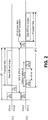
- Fig. 2 shows a timing diagram of an exchange using a delayed clear-to-send, according to an embodiment of the invention.
- STA A transmits an RTS to STA B, which may respond by transmitting a standard CTS back to STA A.
- RTS radio frequency
- CTS channel-to-send
- STA A and STA B may communicate with each other over their directional link L1, and might assume that their communications during SP1 are protected from interference because any devices that overheard the RTS/CTS exchange will know of the reservation.
- STA D may set its NAV in response to detecting the RTS from STA A, that NAV to expire when SP1 expires.
- STA C did not detect the RTS from STA A, and may therefore feel free to transmit its own RTS to STA D, indicating that SP2 will be the duration of the expected subsequent exchanges between STA C and STA D.
- STA D does not immediately respond with a CTS because STA D has its NAV set.
- STA C after waiting for a predetermined period and not hearing a response from STA D, may retransmit the RTS. This delay and retransmit process may be repeated several times if STA D does not respond, although most communication standards specify a maximum number of such retries before giving up and taking another approach.
- the maximum number of retries is not reached.
- STA D's NAV expires at the end of SP1 STA D may note that the time period specified for SP2 has not yet expired and therefore communication with STA C may still be possible.
- STA D then transmits a DCTS back to STA C, without waiting for another RTS.
- STA C and STA D may then perform the desired communication exchange during SP2, although the time remaining in SP2 for such communication has been reduced by the delay caused by the NAV.
- Fig. 2 has the advantage of not requiring STA D to violate its own NAV by transmitting when it is not supposed to.
- a disadvantage is that STA C has no information on why STA D is not responding, and may take corrective action that is not required, unless STA C is programmed not to take such corrective action before the expiration of time period SP1. If SP2 expires before SP1, it may be too late to initiate the desired communications between STA C and STA D, and these devices may take other actions not described here.
- Fig. 3 shows a timing diagram of an exchange using a denial-to-send, according to an embodiment of the invention.
- the initial portions of Fig. 3 are similar to those of Fig. 2 , in which STA D sets its NAV for the time period of SP1 after detecting an RTS (or CTS) from STA A, and STA C transmits its own RTS to STA D during SP1, with the intention of establishing protected communications lasting for time period SP2.
- STA D does not wait, but transmits a DTS while its NAV is still set.
- the format of the DTS is such that when STA C receives it, STA C will know that STA D has its NAV set for the duration of a time specified in the DTS, and STA C should not initiate the desired communications exchange until that time period expires. When the NAV expires, STA C may then retransmit the RTS, and STA D may respond with a CTS in the normal manner, thereby clearing the way for the desired communications exchange between STA C and STA D during the remainder of SP2.
- the technique described in Fig. 3 has the advantage of informing STA C about the NAV status of STA D, so that STA C can wait for the indicated time without resorting to retransmissions or other unnecessary corrective actions. It has the disadvantage of requiring STA D to transmit while its NAV is set. Since STA D would not be able to sense a current transmission from STA B to STA A, this technique could cause STA D's transmission of the DTS to interfere with an existing transmission from STA B to STA A. Whether the technique of Fig. 2 or the technique of Fig. 3 is used, proper precautions may be taken to reduce or eliminate the stated disadvantages.
- Fig. 4 shows a diagram of the format of a delayed clear-to-send, according to an embodiment of the invention.
- This format indicates specific fields of a specific size with specific names, but other formats may also be used.
- the format shown may be part of a medium access control (MAC) header.
- MAC medium access control
- the first field is a Frame Control field, used to identify the type of frame it is. The fact that this is a D-CTS frame may be identified in this field.
- the second field is a Duration field, which may be used to indicate the time remaining in the service period associated with the RTS to which this D-CTS is a response.
- This value may be determined by taking the duration value from the RTS, and subtracting any time that has elapsed before transmission of this D-CTS.
- the RA and TA fields represent the network addresses of the device intended to receive this frame and the device that transmitted this frame, respectively.
- the FCS field is the Frame Check Sequence field, used to validate that the contents of this frame are received correctly. Note: in some embodiments, a D-CTS may be used in place of a standard CTS in some or all instances shown herein, and the terms CTS and D-CTS may be considered interchangeable for the same functional element.
- Fig. 5 shows a diagram of the format of a denial-to-send, according to an embodiment of the invention.
- the RA field may indicate the address of the device intended to receive this frame, and the FCS may be used to validate that the contents of this frame are received correctly.
- the Frame Control field may indentify this as a DTS frame.
- the Duration field may indicate the time remaining in the NAV of the device transmitting this frame.
- the NAV-SA and NAV-DA fields indicate the addresses of the source device and destination device, respectively, whose exchange of the RTS and CTS established the current NAV of the device transmitting this DTS frame.
- NAV-SA would indicate STA A (transmitted the original RTS)
- NAV-DA would indicate STA B (responded by transmitting a CTS).
- Duration field of the DTS indicates how long the other device should wait before initiating the requested communication exchange
- Duration field of the D-CTS indicates how much time the other device has to complete the requested communication exchange.
- Fig. 6 shows two wireless communications devices, according to an embodiment of the invention.
- the two devices are shown communicating with each other and therefore may be used to represent STA C and STA D, but the same internal components may be used to describe any of the communications devices described in this document.
- Device 610 is shown with at least one radio 612 for communicating wirelessly through at least one antenna 618, at least one processor 614 for processing information, and at least one memory 616 to hold data and instructions to be used in that processing.
- Device 650 is similarly shown with at least one radio 652 for communicating wirelessly through at least one antenna 658, at least one processor 654, and at least one memory 656. These items may provide the physical components that enable the functionality described elsewhere in this document.
Landscapes
- Engineering & Computer Science (AREA)
- Computer Networks & Wireless Communication (AREA)
- Signal Processing (AREA)
- Mobile Radio Communication Systems (AREA)
- Small-Scale Networks (AREA)
Abstract
Description
- The popular Request-to-Send/Clear-to-Send (RTS/CTS) mechanism used in WiFi wireless networks provides numerous benefits, including mitigation of the hidden terminal problem and establishment of protection for the subsequent data exchange between two devices. Recently, the same RTS/CTS exchange has been proposed for mmWave (e.g., 60GHz) communications, which are characterized by directional communications. However, due to the nature of directional transmissions and receptions, a new type of hidden terminal problem has been introduced which is not resolved by the standard RTS/CTS protocol. For example, when a first device has established a directional link with a second device in a direction that encompasses an unrelated third device, and detects an RTS from that third device, the first device knows to sets its Network Allocation Vector (NAV) so that it won't transmit during the time period specified in that RTS. However, when the directionality is such that the first device detects the RTS but the second device does not, the second device may transmit its own RTS to the first device, but the first device cannot transmit a CTS back because its own NAV was set by the first RTS. When the second device doesn't receive the expected CTS, it may initiate unneeded corrective action, such as repeating the RTS several times, and if it assumes the directional link has been lost, initiating a time consuming and unnecessary beam forming operation.
- Some embodiments of the invention may be understood by referring to the following description and accompanying drawings that are used to illustrate embodiments of the invention. In the drawings:
-
Fig. 1 shows two pair of wireless communication devices using directional links, according to an embodiment of the invention. -
Fig. 2 shows a timing diagram of an exchange using a delayed clear-to-send, according to an embodiment of the invention. -
Fig. 3 shows a timing diagram of an exchange using a denial-to-send, according to an embodiment of the invention. -
Fig. 4 shows a diagram of the format of a delayed clear-to-send, according to an embodiment of the invention. -
Fig. 5 shows a diagram of the format of a denial-to-send, according to an embodiment of the invention. -
Fig. 6 shows two wireless communications devices, according to an embodiment of the invention. - In the following description, numerous specific details are set forth. However, it is understood that embodiments of the invention may be practiced without these specific details. In other instances, well-known circuits, structures and techniques have not been shown in detail in order not to obscure an understanding of this description.
- References to "one embodiment", "an embodiment", "example embodiment", "various embodiments", etc., indicate that the embodiment(s) of the invention so described may include particular features, structures, or characteristics, but not every embodiment necessarily includes the particular features, structures, or characteristics. Further, some embodiments may have some, all, or none of the features described for other embodiments.
- In the following description and claims, the terms "coupled" and "connected," along with their derivatives, may be used. It should be understood that these terms are not intended as synonyms for each other. Rather, in particular embodiments, "connected" is used to indicate that two or more elements are in direct physical or electrical contact with each other. "Coupled" is used to indicate that two or more elements co-operate or interact with each other, but they may or may not be in direct physical or electrical contact.
- As used in the claims, unless otherwise specified the use of the ordinal adjectives "first", "second", "third", etc., to describe a common element, merely indicate that different instances of like elements are being referred to, and are not intended to imply that the elements so described must be in a given sequence, either temporally, spatially, in ranking, or in any other manner.
- Various embodiments of the invention may be implemented in one or any combination of hardware, firmware, and software. The invention may also be implemented as instructions contained in or on a computer-readable storage medium, which may be read and executed by one or more processors to enable performance of the operations described herein. A computer-readable storage medium may include any mechanism for storing information in a form readable by one or more computers. For example, a computer-readable storage medium may include things such as, but not limited to, read only memory (ROM); random access memory (RAM); magnetic disk storage
- The term "wireless" may be used to describe circuits, devices, systems, methods, techniques, communications channels, etc., that communicate data by using modulated electromagnetic radiation through a non-solid medium. The term does not imply that the associated devices do not contain any wires, although in some embodiments they might not. A wireless device may comprise at least one antenna, at least one radio, and at least one processor, and at least one memory, where the radio transmits signals through the antenna that represent data and receives signals through the antenna that represent data, while the processor may process the data to be transmitted and the data that has been received. The processor may also process other data, which is neither transmitted nor received. For convenience of reference within this document, each wireless communications device may be labeled as a STA, but the various embodiments of the invention are not limited to devices identified with this label. Other common terms may also be used, such as but not limited to a mobile station, DEV, etc., and still fall within the scope of the embodiments of the invention.
- Within the context of this document, a directional transmission means the transmission is relatively strong in one direction and relatively weak in the other directions, within the intended frequency band. A directional reception means the receiving device can receive signals from one direction more easily than it can receive equivalent strength signals from other directions, within the intended frequency band. Directional communications include both directional transmissions and directional receptions. A directional link means that two devices have established the parameters for directional transmission and directional reception in communications with each other.
- Within the context of this document, a "Network Allocation Vector" (NAV) is a period of time that expires at a designated time indicated in a message. "Setting a NAV" means setting a timer to measure the period of time that will expire at the end of that NAV. "Expiration of the NAV" means expiration of the time period indicated with the timer.
-
Fig. 1 shows two pair of wireless communication devices using directional links, according to an embodiment of the invention. In the illustrated embodiments, it is assumed that STA A and STA B have already established a directional link L1 with each other, and that STA C and STA D have already established a directional link L2 with each other, with each STA's transmissions and receptions being focused in the direction of the arrow. It is further assumed that the physical location of these STAs is such that directional transmissions from STA A will reach STAs C and D, and that STA D can receive these transmissions (because its receiver is directed towards STA A) but STA C cannot receive these transmissions (because its receiver is directed away from STA A). - In the example operation, STA A may transmit an RTS to STA B, which responds by transmitting a CTS to STA A. However, because of their respective locations and directionality, STA D may also detect this RTS. Since STA D was not addressed by the RTS from STA A, STA D may set its NAV for the time period specified in the RTS from STA A, and suspend transmitting during that time. (Note: in some protocols, both the RTS and CTS contain information indicating the time remaining in the NAV period. In such an instance STA D would set its NAV if it overheard either an RTS or a CTS from STA A. The NAV would expire at the same time either way.) Shortly afterwards, STA C (which did not detect the RTS from STA A and therefore does not know about the NAV) may transmit its own RTS to STA D. Without the interfering presence of link L1, STA D would normally respond by promptly transmitting a CTS back to STA C. But because of the earlier detection of an RTS from STA A, under conventional operations STA C should not respond promptly with a CTS because its NAV is still set. However, under the embodiments of the invention described herein, STA C can respond in a non-conventional way by transmitting either of two responses. Within this document, these responses are labeled a denial-to-send (DTS), which may sometimes be referred to as a mmWaveDTS, and a delayed clear-to-send (D-CTS), which may sometimes be referred to as a mmWaveCTS. A DTS response indicates that the device responding to the RTS has its NAV set, and that the NAV will expire at a time indicated by the DTS. By contrast, the time specified in a D-CTS may indicate the time remaining in the time period specified by the RTS to which the device is responding. In some embodiments, a D-CTS may be used in the same situations as a standard CTS (i.e., even if the response is not delayed), since both indicate an ability to immediately proceed with communications.
-
Fig. 2 shows a timing diagram of an exchange using a delayed clear-to-send, according to an embodiment of the invention. Using the same scenario described forFig. 1 , during service period 1 (SP1) STA A transmits an RTS to STA B, which may respond by transmitting a standard CTS back to STA A. Either the RTS, or the CTS, or both, may be considered as making a network reservation, since the purpose of this exchange is to reserve the channel(s) for subsequent communication between these two devices. Once the RTS/CTS exchange has taken place, STA A and STA B may communicate with each other over their directional link L1, and might assume that their communications during SP1 are protected from interference because any devices that overheard the RTS/CTS exchange will know of the reservation. - As described earlier, STA D may set its NAV in response to detecting the RTS from STA A, that NAV to expire when SP1 expires. However, STA C did not detect the RTS from STA A, and may therefore feel free to transmit its own RTS to STA D, indicating that SP2 will be the duration of the expected subsequent exchanges between STA C and STA D. But STA D does not immediately respond with a CTS because STA D has its NAV set. STA C, after waiting for a predetermined period and not hearing a response from STA D, may retransmit the RTS. This delay and retransmit process may be repeated several times if STA D does not respond, although most communication standards specify a maximum number of such retries before giving up and taking another approach.
- In the example of
Fig. 2 , the maximum number of retries is not reached. When STA D's NAV expires at the end of SP1, STA D may note that the time period specified for SP2 has not yet expired and therefore communication with STA C may still be possible. STA D then transmits a DCTS back to STA C, without waiting for another RTS. When STA C receives the DCTS, STA C and STA D may then perform the desired communication exchange during SP2, although the time remaining in SP2 for such communication has been reduced by the delay caused by the NAV. - The technique described in
Fig. 2 has the advantage of not requiring STA D to violate its own NAV by transmitting when it is not supposed to. A disadvantage is that STA C has no information on why STA D is not responding, and may take corrective action that is not required, unless STA C is programmed not to take such corrective action before the expiration of time period SP1. If SP2 expires before SP1, it may be too late to initiate the desired communications between STA C and STA D, and these devices may take other actions not described here. -
Fig. 3 shows a timing diagram of an exchange using a denial-to-send, according to an embodiment of the invention. The initial portions ofFig. 3 are similar to those ofFig. 2 , in which STA D sets its NAV for the time period of SP1 after detecting an RTS (or CTS) from STA A, and STA C transmits its own RTS to STA D during SP1, with the intention of establishing protected communications lasting for time period SP2. However, in this embodiment STA D does not wait, but transmits a DTS while its NAV is still set. The format of the DTS is such that when STA C receives it, STA C will know that STA D has its NAV set for the duration of a time specified in the DTS, and STA C should not initiate the desired communications exchange until that time period expires. When the NAV expires, STA C may then retransmit the RTS, and STA D may respond with a CTS in the normal manner, thereby clearing the way for the desired communications exchange between STA C and STA D during the remainder of SP2. - The technique described in
Fig. 3 has the advantage of informing STA C about the NAV status of STA D, so that STA C can wait for the indicated time without resorting to retransmissions or other unnecessary corrective actions. It has the disadvantage of requiring STA D to transmit while its NAV is set. Since STA D would not be able to sense a current transmission from STA B to STA A, this technique could cause STA D's transmission of the DTS to interfere with an existing transmission from STA B to STA A. Whether the technique ofFig. 2 or the technique ofFig. 3 is used, proper precautions may be taken to reduce or eliminate the stated disadvantages. -
Fig. 4 shows a diagram of the format of a delayed clear-to-send, according to an embodiment of the invention. This format indicates specific fields of a specific size with specific names, but other formats may also be used. The format shown may be part of a medium access control (MAC) header. In the illustrated example ofFig. 4 , the first field is a Frame Control field, used to identify the type of frame it is. The fact that this is a D-CTS frame may be identified in this field. The second field is a Duration field, which may be used to indicate the time remaining in the service period associated with the RTS to which this D-CTS is a response. This value may be determined by taking the duration value from the RTS, and subtracting any time that has elapsed before transmission of this D-CTS. The RA and TA fields represent the network addresses of the device intended to receive this frame and the device that transmitted this frame, respectively. The FCS field is the Frame Check Sequence field, used to validate that the contents of this frame are received correctly. Note: in some embodiments, a D-CTS may be used in place of a standard CTS in some or all instances shown herein, and the terms CTS and D-CTS may be considered interchangeable for the same functional element. -
Fig. 5 shows a diagram of the format of a denial-to-send, according to an embodiment of the invention. Similar to the format ofFig. 4 , the RA field may indicate the address of the device intended to receive this frame, and the FCS may be used to validate that the contents of this frame are received correctly. The Frame Control field may indentify this as a DTS frame. The Duration field may indicate the time remaining in the NAV of the device transmitting this frame. The NAV-SA and NAV-DA fields indicate the addresses of the source device and destination device, respectively, whose exchange of the RTS and CTS established the current NAV of the device transmitting this DTS frame. In the previous examples, NAV-SA would indicate STA A (transmitted the original RTS), and NAV-DA would indicate STA B (responded by transmitting a CTS). One of the important differences between the contents of the D-CTS and the DTS is that the Duration field of the DTS indicates how long the other device should wait before initiating the requested communication exchange, while the Duration field of the D-CTS indicates how much time the other device has to complete the requested communication exchange. -
Fig. 6 shows two wireless communications devices, according to an embodiment of the invention. The two devices are shown communicating with each other and therefore may be used to represent STA C and STA D, but the same internal components may be used to describe any of the communications devices described in this document.Device 610 is shown with at least oneradio 612 for communicating wirelessly through at least oneantenna 618, at least oneprocessor 614 for processing information, and at least onememory 616 to hold data and instructions to be used in that processing.Device 650 is similarly shown with at least oneradio 652 for communicating wirelessly through at least oneantenna 658, at least oneprocessor 654, and at least onememory 656. These items may provide the physical components that enable the functionality described elsewhere in this document. - This disclosure also extends to the subject matters defined in the following numbered
clauses 1 to 19. -
Clause 1. An apparatus, comprising a first device for performing wireless directional communications with a second device, the wireless directional communications comprising: setting a network allocation vector (NAV) in response to detecting a network reservation from a third device; receiving, during a time period indicated by the NAV, a request-to-send (RTS) from the second device; transmitting, to the second device, either a denial-to-send (DTS) before expiration of the NAV or a delayed clear-to-send (D-CTS) after expiration of the NAV; and performing communications with the second device after expiration of the NAV and after said transmitting, said communications taking place during a time period indicated by the RTS from the second device. -
Clause 2. The apparatus ofclause 1, wherein: said transmitting comprises transmitting a DTS; and the first device is to receive a second RTS from the second device after expiration of the NAV and is to transmit a clear-to-send (CTS) after receiving the second RTS but before said performing. - Clause 3. The apparatus of
clause 2, wherein the DTS comprises a frame control message indicating a time remaining in the NAV. -
Clause 4. The apparatus ofclause 1, wherein the network reservation comprises either an RTS or a CTS transmitted by the third device and not addressed to the first device. - Clause 5. The apparatus of
clause 1, further comprising at least one antenna. -
Clause 6. A method, comprising communicating wirelessly with a second device, by performing operations in a first device, said operations comprising: setting a network allocation vector (NAV) in response to detecting either a request to send (RTS) from a third device or a clear-to-send (CTS) from the third device; receiving, during a time period indicated by the NAV, a request-to-send (RTS) from the second device; transmitting, to the second device, a denial-to-send (DTS) before expiration of the NAV; and performing communications with the second device after expiration of the NAV; wherein said receiving, said transmitting, and said performing communications each comprise using a directional link. - Clause 7. The method of
clause 6, further comprising: receiving a another RTS from the second device after expiration of the NAV; and transmitting a clear-to-send (CTS) after receiving the second RTS but before said performing. - Clause 8. The method of clause 7, wherein the DTS comprises a duration field indicating a time remaining in the NAV.
- Clause 9. An article comprising a computer-readable storage medium that contains instructions, which when executed by one or more processors result in performing operations comprising: setting a network allocation vector (NAV) in response to detecting either a request to send (RTS) from a third device or a clear-to-send (CTS) from the third device; receiving, during a time period indicated by the NAV, a request-to-send (RTS) from the second device; transmitting, to the second device, a denial-to-send (DTS) before expiration of the NAV; and performing communications with the second device after expiration of the
NAV; wherein the operations of receiving, transmitting, and performing take place over a directional link. - Clause 10. The article of clause 9, further comprising: receiving another RTS from the second device after expiration of the NAV; and transmitting a clear-to-send (CTS) after receiving the second RTS but before said performing.
- Clause 11. The article of clause 9, wherein the DTS comprises a frame control message indicating a time remaining in the NAV.
- Clause 12. An apparatus, comprising a first device for performing wireless directional communications with a second device over a directional link, the wireless directional communications comprising: transmitting a request-to-send (RTS) to the second device; receiving a denial-to-send (DTS) from the second device, the DTS containing a duration value indicating time remaining for a network allocation vector (NAV) that has been set in the second device; and performing subsequent communications with the second device only after expiration of the NAV.
- Clause 13. The apparatus of clause 12, further comprising at least one antenna.
- Clause 14. A method, comprising communicating wirelessly with a second device, by performing operations in a first device, said communicating comprising: transmitting a request-to-send (RTS) to the second device; receiving a denial-to-send (DTS) from the second device; and performing subsequent communications with the second device only after expiration of a time period indicated in the DTS; wherein said transmitting, said receiving, and said performing each comprise using a directional link.
- Clause 15. The method of clause 14, further comprising: transmitting a second RTS to the second device after said expiration of the time period; and receiving a clear-to-send (CTS) from the second device after transmitting the second RTS but before said performing the subsequent communications.
- Clause 16. The method of clause 15, wherein the DTS comprises a frame control message.
- Clause 17. An article comprising a computer-readable storage medium that contains instructions, which when executed by one or more processors result in performing operations comprising: transmitting a request-to-send (RTS) to a wireless communications device; receiving a denial-to-send (DTS) from the wireless communication device; and performing subsequent communications with the wireless communications device only after expiration of a time period indicated in the DTS.
- Clause 18. The article of clause 17, wherein the operations further comprise: transmitting a second RTS to the wireless communications device after said expiration of the time period; and receiving a clear-to-send (CTS) from the wireless communications device after transmitting the second RTS.
- Clause 19. The article of clause 18, wherein the DTS comprises a frame control message.
- The foregoing description is intended to be illustrative and not limiting. Variations will occur to those of skill in the art. Those variations are intended to be included in the various embodiments of the invention.
Claims (15)
- A device comprising memory and processing circuitry configured to:identify a directional transmission received from a second device, wherein the directional transmission is received in a first direction;set a network allocation vector "NAV" for the device based at least in part on the directional transmission;identify, during a time associated with the NAV, a directional request to send "RTS" received from a third device, wherein the directional RTS is received in a second direction that is different from the first direction, and wherein the directional RTS indicates a service period associated with the third device; andcause to send a directional response to the third device during the service period.
- The device of claim 1, wherein to cause to send the directional response comprises the memory and processing circuitry being further configured to cause to send the directional response before a time associated with the NAV has expired.
- The device of claim 1 or claim 2, wherein the directional response is a denial to send comprising an indication of the NAV.
- The device of claim 2, wherein the memory and processing circuitry are further configured to determine that the time associated with the NAV will expire after the service period expires, wherein to cause to send the directional response comprises the memory and processing circuitry being further configured to cause to send the directional response based at least in part on the determination that the time associated with the NAV will expire after the service period.
- The device of claim 2, wherein the directional RTS is a first directional RTS, wherein the service period is a first service period, wherein the directional response is a first directional response, and wherein the memory and processing circuitry are further configured to:identify a second directional RTS received from the third device, wherein the second directional RTS is received in the second direction, and wherein the second directional RTS indicates a second service period associated with the third device; andcause to send a second directional response to the third device during the second service period.
- The device of claim 1, wherein the memory and processing circuitry are further configured to determine that the time associated with the NAV has expired before an expiration of the service period, wherein to cause to send the directional response comprises the memory and processing circuitry being further configured to cause to send the directional response after the time associated with the NAV has expired.
- The device of claim 1 or claim 6, wherein the directional response is a clear to send.
- The device of any of claims 1-7, wherein the directional transmission is an RTS.
- The device of any of claims 1-7, wherein the directional transmission is a clear to send.
- The device of claim 1, further comprising a transceiver configured to transmit and receive wireless signals.
- The device of claim 10, further comprising one or more antennas coupled to the transceiver.
- An apparatus, comprising:means for identifying a directional transmission received from a first device, wherein the directional transmission is received in a first direction;means for setting a network allocation vector "NAV" for the apparatus based at least in part on the directional transmission;means for identifying, during a time associated with the NAV, a directional request to send "RTS" received from a second device, wherein the directional RTS is received in a second direction that is different from the first direction, and wherein the directional RTS indicates a service period associated with the second device; andmeans for causing to send a directional response to the second device during the service period.
- The apparatus of claim 12, wherein the directional response is a denial to send comprising an indication of the NAV, the apparatus further comprising means for determining that the time associated with the NAV will expire after the service period expires, wherein the means for causing to send the directional response comprises means for causing to send the directional response based at least in part on the determination that the time associated with the NAV will expire after the service period.
- The apparatus of claim 12, further comprising means for determining that the time associated with the NAV has expired before an expiration of the service period, wherein the means for causing to send the directional response comprises means for causing to send the directional response after the time associated with the NAV has expired.
- The apparatus of an of claims 12-14, wherein the directional transmission is an RTS.
Applications Claiming Priority (3)
| Application Number | Priority Date | Filing Date | Title |
|---|---|---|---|
| US12/459,151 US8503359B2 (en) | 2009-06-26 | 2009-06-26 | Use of delayed clear-to-send and denial-to-send in directional wireless networks |
| EP10792486.2A EP2446694A4 (en) | 2009-06-26 | 2010-05-05 | Use of delayed clear-to-send and denial-to-send in directional wireless networks |
| PCT/US2010/033717 WO2010151377A2 (en) | 2009-06-26 | 2010-05-05 | Use of delayed clear-to-send and denial-to-send in directional wireless networks |
Related Parent Applications (1)
| Application Number | Title | Priority Date | Filing Date |
|---|---|---|---|
| EP10792486.2A Division EP2446694A4 (en) | 2009-06-26 | 2010-05-05 | Use of delayed clear-to-send and denial-to-send in directional wireless networks |
Publications (2)
| Publication Number | Publication Date |
|---|---|
| EP3379887A1 true EP3379887A1 (en) | 2018-09-26 |
| EP3379887B1 EP3379887B1 (en) | 2024-07-03 |
Family
ID=43380631
Family Applications (2)
| Application Number | Title | Priority Date | Filing Date |
|---|---|---|---|
| EP18160316.8A Active EP3379887B1 (en) | 2009-06-26 | 2010-05-05 | Use of delayed clear-to-send and denial-to-send in directional wireless networks |
| EP10792486.2A Withdrawn EP2446694A4 (en) | 2009-06-26 | 2010-05-05 | Use of delayed clear-to-send and denial-to-send in directional wireless networks |
Family Applications After (1)
| Application Number | Title | Priority Date | Filing Date |
|---|---|---|---|
| EP10792486.2A Withdrawn EP2446694A4 (en) | 2009-06-26 | 2010-05-05 | Use of delayed clear-to-send and denial-to-send in directional wireless networks |
Country Status (8)
| Country | Link |
|---|---|
| US (1) | US8503359B2 (en) |
| EP (2) | EP3379887B1 (en) |
| JP (1) | JP5345733B2 (en) |
| KR (1) | KR101342727B1 (en) |
| CN (2) | CN101938845B (en) |
| BR (1) | BRPI1009681B1 (en) |
| SG (2) | SG186691A1 (en) |
| WO (1) | WO2010151377A2 (en) |
Cited By (1)
| Publication number | Priority date | Publication date | Assignee | Title |
|---|---|---|---|---|
| WO2025071667A1 (en) * | 2023-09-27 | 2025-04-03 | Intel Corporation | Communication station and apparatus used therein |
Families Citing this family (13)
| Publication number | Priority date | Publication date | Assignee | Title |
|---|---|---|---|---|
| US8503359B2 (en) | 2009-06-26 | 2013-08-06 | Intel Corporation | Use of delayed clear-to-send and denial-to-send in directional wireless networks |
| US8428518B2 (en) * | 2009-09-11 | 2013-04-23 | Intel Corporation | Traffic constraints in a mmWAVE wireless network |
| JP2013093717A (en) * | 2011-10-25 | 2013-05-16 | Fujitsu Ltd | Radio station, communication system, and communication method |
| US9736862B2 (en) * | 2012-12-12 | 2017-08-15 | Qualcomm Incorporated | Systems and methods for delay indication in a wireless message |
| WO2015023143A1 (en) * | 2013-08-14 | 2015-02-19 | 엘지전자 주식회사 | Method and device for transmitting data in wireless lan |
| US20150063251A1 (en) * | 2013-08-30 | 2015-03-05 | Qualcomm Incorporated | Methods and apparatus for extending a reverse direction grant on a wireless network |
| US9923663B2 (en) * | 2014-03-28 | 2018-03-20 | Intel IP Corporation | Methods and arrangements for time-sharing in a dense environment |
| RU2681350C1 (en) * | 2015-06-05 | 2019-03-06 | Телефонактиеболагет Лм Эрикссон (Пабл) | Station, access point and implemented wireless transfer treatment methods in a wireless communication network |
| US10362586B2 (en) * | 2015-10-13 | 2019-07-23 | Futurewei Technologies, Inc. | System and method for spatial reuse in directional random access |
| US20170290058A1 (en) * | 2016-04-01 | 2017-10-05 | Sarabjot Singh | Systems and methods for avoiding hidden node collisions |
| EP3498027B1 (en) * | 2016-08-11 | 2023-05-24 | Intel Corporation | Denial to send frame for multiple channel access |
| US10405348B2 (en) * | 2016-10-25 | 2019-09-03 | Qualcomm Incorporated | Slotted transmission and directional reception of RTS |
| US11696330B2 (en) | 2017-05-31 | 2023-07-04 | Telefonaktiebolaget Lm Ericsson (Publ) | Network node, wireless device and methods for handling interference |
Citations (3)
| Publication number | Priority date | Publication date | Assignee | Title |
|---|---|---|---|---|
| EP1667367A1 (en) * | 2004-05-31 | 2006-06-07 | Matsushita Electric Industrial Co., Ltd. | Radio communication method and radio communication device |
| JP2006186603A (en) * | 2004-12-27 | 2006-07-13 | Advanced Telecommunication Research Institute International | Wireless device |
| US20060227802A1 (en) * | 2005-03-31 | 2006-10-12 | Lei Du | Method and apparatus for implementing medium access control in wireless distributed network |
Family Cites Families (11)
| Publication number | Priority date | Publication date | Assignee | Title |
|---|---|---|---|---|
| CA2439697C (en) * | 2001-03-02 | 2007-11-13 | At&T Corp. | Interference suppression methods for 802.11 |
| JP2003163669A (en) | 2001-11-27 | 2003-06-06 | Canon Inc | Wireless communication device |
| CN101159518B (en) * | 2003-02-03 | 2012-02-22 | 索尼株式会社 | Communication method and communication device |
| US7826431B2 (en) * | 2004-05-14 | 2010-11-02 | Interdigital Technology Corporation | Method of selectively adjusting the configuration of an access point antenna to enhance mobile station coverage |
| JP2006261984A (en) | 2005-03-16 | 2006-09-28 | Mitsubishi Electric Corp | Communication method |
| US7613138B2 (en) * | 2005-05-23 | 2009-11-03 | Microsoft Corporation | Separating control and data in wireless networks |
| CN101248687A (en) | 2005-06-08 | 2008-08-20 | 阿瓦雅技术公司 | Avoiding exposed node problems in wireless local area networks |
| US7656854B2 (en) * | 2005-06-08 | 2010-02-02 | Avaya Inc. | Avoiding hidden terminals in wireless local area networks |
| US8879573B2 (en) * | 2006-12-01 | 2014-11-04 | Microsoft Corporation | Media access control (MAC) protocol for cognitive wireless networks |
| US8837435B2 (en) * | 2007-10-31 | 2014-09-16 | Samsung Electronics Co., Ltd. | Method and system for medium access control in communication networks |
| US8503359B2 (en) | 2009-06-26 | 2013-08-06 | Intel Corporation | Use of delayed clear-to-send and denial-to-send in directional wireless networks |
-
2009
- 2009-06-26 US US12/459,151 patent/US8503359B2/en active Active
-
2010
- 2010-05-05 BR BRPI1009681-7A patent/BRPI1009681B1/en active IP Right Grant
- 2010-05-05 EP EP18160316.8A patent/EP3379887B1/en active Active
- 2010-05-05 KR KR1020117031026A patent/KR101342727B1/en active Active
- 2010-05-05 SG SG2012096814A patent/SG186691A1/en unknown
- 2010-05-05 SG SG2011082245A patent/SG175956A1/en unknown
- 2010-05-05 EP EP10792486.2A patent/EP2446694A4/en not_active Withdrawn
- 2010-05-05 JP JP2012516087A patent/JP5345733B2/en active Active
- 2010-05-05 WO PCT/US2010/033717 patent/WO2010151377A2/en not_active Ceased
- 2010-06-25 CN CN201010221476.XA patent/CN101938845B/en active Active
- 2010-06-25 CN CN201210574966.7A patent/CN103067930B/en active Active
Patent Citations (3)
| Publication number | Priority date | Publication date | Assignee | Title |
|---|---|---|---|---|
| EP1667367A1 (en) * | 2004-05-31 | 2006-06-07 | Matsushita Electric Industrial Co., Ltd. | Radio communication method and radio communication device |
| JP2006186603A (en) * | 2004-12-27 | 2006-07-13 | Advanced Telecommunication Research Institute International | Wireless device |
| US20060227802A1 (en) * | 2005-03-31 | 2006-10-12 | Lei Du | Method and apparatus for implementing medium access control in wireless distributed network |
Non-Patent Citations (4)
| Title |
|---|
| BHARGHAVAN V ET AL: "MACAW: A MEDIA ACCESS PROTOCOL FOR WIRELESS LAN'S", COMPUTER COMMUNICATION REVIEW, ACM, NEW YORK, NY, US, vol. 24, no. 4, 1 October 1994 (1994-10-01), pages 212 - 225, XP000477053, ISSN: 0146-4833, DOI: 10.1145/190809.190334 * |
| BORDIM J L ET AL: "Limiting the Effects of Deafness and Hidden Terminal Problems in Directional Communications", 1 January 2006, PARALLEL AND DISTRIBUTED PROCESSING AND APPLICATIONS LECTURE NOTES IN COMPUTER SCIENCE;;LNCS, SPRINGER, BERLIN, DE, PAGE(S) 195 - 206, ISBN: 978-3-540-68067-3, XP019052616 * |
| KO Y-B ET AL: "MEDIUM ACCESS CONTROL PROTOCOLS USING DIRECTIONAL ANTENNAS IN AD HOC NETWORKS", PROCEEDINGS IEEE INFOCOM 2000. THE CONFERENCE ON COMPUTER COMMUNICATIONS. 19TH. ANNUAL JOINT CONFERENCE OF THE IEEE COMPUTER AND COMMUNICATIONS SOCIETIES. TEL AVIV, ISRAEL, MARCH, 26-30, 2000; [PROCEEDINGS IEEE INFOCOM. THE CONFERENCE ON COMPUTER COM, vol. CONF. 19, 26 March 2000 (2000-03-26), pages 13 - 21, XP001004229, ISBN: 978-0-7803-5881-2 * |
| KORAKIS T ET AL: "CDR-MAC: A Protocol for Full Exploitation of Directional Antennas in Ad Hoc Wireless Networks", IEEE TRANSACTIONS ON MOBILE COMPUTING, IEEE SERVICE CENTER, LOS ALAMITOS, CA, US, vol. 7, no. 2, 1 February 2008 (2008-02-01), pages 145 - 155, XP011335210, ISSN: 1536-1233, DOI: 10.1109/TMC.2007.70705 * |
Cited By (1)
| Publication number | Priority date | Publication date | Assignee | Title |
|---|---|---|---|---|
| WO2025071667A1 (en) * | 2023-09-27 | 2025-04-03 | Intel Corporation | Communication station and apparatus used therein |
Also Published As
| Publication number | Publication date |
|---|---|
| EP2446694A2 (en) | 2012-05-02 |
| EP2446694A4 (en) | 2015-07-29 |
| US8503359B2 (en) | 2013-08-06 |
| CN101938845B (en) | 2015-05-27 |
| WO2010151377A2 (en) | 2010-12-29 |
| CN103067930B (en) | 2016-04-27 |
| BRPI1009681B1 (en) | 2021-03-16 |
| SG175956A1 (en) | 2011-12-29 |
| WO2010151377A3 (en) | 2011-03-03 |
| CN101938845A (en) | 2011-01-05 |
| EP3379887B1 (en) | 2024-07-03 |
| US20100329178A1 (en) | 2010-12-30 |
| JP5345733B2 (en) | 2013-11-20 |
| KR101342727B1 (en) | 2013-12-19 |
| JP2012531093A (en) | 2012-12-06 |
| CN103067930A (en) | 2013-04-24 |
| BRPI1009681A2 (en) | 2016-03-15 |
| KR20120024849A (en) | 2012-03-14 |
| SG186691A1 (en) | 2013-01-30 |
Similar Documents
| Publication | Publication Date | Title |
|---|---|---|
| US8503359B2 (en) | Use of delayed clear-to-send and denial-to-send in directional wireless networks | |
| CN102209353B (en) | Enhanced carrier sensing for multi-channel operation | |
| KR101451043B1 (en) | Method of collision resolution in a wide channel | |
| US20020150095A1 (en) | Interference suppression methods for 802.11 | |
| CN107079470B (en) | Media access control for licensed assisted access | |
| US20190053279A1 (en) | Method and system for optimizing channel access in a wireless local area network | |
| US10306602B2 (en) | Data transmission method and apparatus | |
| US8755402B2 (en) | Medium reservation protocol for directional wireless networks | |
| US20150124723A1 (en) | Wireless communication apparatus, wireless communication method, processing apparatus, and program | |
| JPWO2017077686A1 (en) | Base station apparatus, radio terminal apparatus, and radio communication method | |
| KR20230125299A (en) | Channel access procedures | |
| KR101306210B1 (en) | Method for medium access control in single channel wireless network | |
| US20260129670A1 (en) | Wireless communication device and method for intra-bss interference mitigation via non-primary channel access | |
| WO2025213346A1 (en) | Transmission method for available window of wireless communication device, wireless communication method in case of in-device interference, wireless communication device and storage medium | |
| US11696330B2 (en) | Network node, wireless device and methods for handling interference | |
| WO2024171386A1 (en) | Terminal device, base station device, and wireless communication system |
Legal Events
| Date | Code | Title | Description |
|---|---|---|---|
| PUAI | Public reference made under article 153(3) epc to a published international application that has entered the european phase |
Free format text: ORIGINAL CODE: 0009012 |
|
| STAA | Information on the status of an ep patent application or granted ep patent |
Free format text: STATUS: REQUEST FOR EXAMINATION WAS MADE |
|
| 17P | Request for examination filed |
Effective date: 20180306 |
|
| AC | Divisional application: reference to earlier application |
Ref document number: 2446694 Country of ref document: EP Kind code of ref document: P |
|
| AK | Designated contracting states |
Kind code of ref document: A1 Designated state(s): AL AT BE BG CH CY CZ DE DK EE ES FI FR GB GR HR HU IE IS IT LI LT LU LV MC MK MT NL NO PL PT RO SE SI SK SM TR |
|
| STAA | Information on the status of an ep patent application or granted ep patent |
Free format text: STATUS: EXAMINATION IS IN PROGRESS |
|
| 17Q | First examination report despatched |
Effective date: 20191106 |
|
| RAP1 | Party data changed (applicant data changed or rights of an application transferred) |
Owner name: TAHOE RESEARCH, LTD. |
|
| REG | Reference to a national code |
Ref country code: DE Ref legal event code: R079 Ref document number: 602010069443 Country of ref document: DE Free format text: PREVIOUS MAIN CLASS: H04W0074080000 Ipc: H04W0074081600 Ref country code: DE Ref legal event code: R079 Free format text: PREVIOUS MAIN CLASS: H04W0074080000 Ipc: H04W0074081600 |
|
| GRAP | Despatch of communication of intention to grant a patent |
Free format text: ORIGINAL CODE: EPIDOSNIGR1 |
|
| STAA | Information on the status of an ep patent application or granted ep patent |
Free format text: STATUS: GRANT OF PATENT IS INTENDED |
|
| RIC1 | Information provided on ipc code assigned before grant |
Ipc: H04W 74/0816 20240101AFI20240123BHEP Ipc: H04W 84/18 20090101ALN20240123BHEP Ipc: H04W 74/00 20090101ALN20240123BHEP Ipc: H04W 16/28 20090101ALN20240123BHEP |
|
| INTG | Intention to grant announced |
Effective date: 20240206 |
|
| GRAS | Grant fee paid |
Free format text: ORIGINAL CODE: EPIDOSNIGR3 |
|
| GRAA | (expected) grant |
Free format text: ORIGINAL CODE: 0009210 |
|
| STAA | Information on the status of an ep patent application or granted ep patent |
Free format text: STATUS: THE PATENT HAS BEEN GRANTED |
|
| AC | Divisional application: reference to earlier application |
Ref document number: 2446694 Country of ref document: EP Kind code of ref document: P |
|
| AK | Designated contracting states |
Kind code of ref document: B1 Designated state(s): AL AT BE BG CH CY CZ DE DK EE ES FI FR GB GR HR HU IE IS IT LI LT LU LV MC MK MT NL NO PL PT RO SE SI SK SM TR |
|
| REG | Reference to a national code |
Ref country code: CH Ref legal event code: EP |
|
| REG | Reference to a national code |
Ref country code: DE Ref legal event code: R096 Ref document number: 602010069443 Country of ref document: DE |
|
| REG | Reference to a national code |
Ref country code: LT Ref legal event code: MG9D |
|
| REG | Reference to a national code |
Ref country code: NL Ref legal event code: MP Effective date: 20240703 |
|
| PG25 | Lapsed in a contracting state [announced via postgrant information from national office to epo] |
Ref country code: PT Free format text: LAPSE BECAUSE OF FAILURE TO SUBMIT A TRANSLATION OF THE DESCRIPTION OR TO PAY THE FEE WITHIN THE PRESCRIBED TIME-LIMIT Effective date: 20241104 |
|
| REG | Reference to a national code |
Ref country code: AT Ref legal event code: MK05 Ref document number: 1701094 Country of ref document: AT Kind code of ref document: T Effective date: 20240703 |
|
| PG25 | Lapsed in a contracting state [announced via postgrant information from national office to epo] |
Ref country code: NL Free format text: LAPSE BECAUSE OF FAILURE TO SUBMIT A TRANSLATION OF THE DESCRIPTION OR TO PAY THE FEE WITHIN THE PRESCRIBED TIME-LIMIT Effective date: 20240703 |
|
| PG25 | Lapsed in a contracting state [announced via postgrant information from national office to epo] |
Ref country code: PT Free format text: LAPSE BECAUSE OF FAILURE TO SUBMIT A TRANSLATION OF THE DESCRIPTION OR TO PAY THE FEE WITHIN THE PRESCRIBED TIME-LIMIT Effective date: 20241104 Ref country code: NL Free format text: LAPSE BECAUSE OF FAILURE TO SUBMIT A TRANSLATION OF THE DESCRIPTION OR TO PAY THE FEE WITHIN THE PRESCRIBED TIME-LIMIT Effective date: 20240703 |
|
| PG25 | Lapsed in a contracting state [announced via postgrant information from national office to epo] |
Ref country code: NO Free format text: LAPSE BECAUSE OF FAILURE TO SUBMIT A TRANSLATION OF THE DESCRIPTION OR TO PAY THE FEE WITHIN THE PRESCRIBED TIME-LIMIT Effective date: 20241003 |
|
| PG25 | Lapsed in a contracting state [announced via postgrant information from national office to epo] |
Ref country code: PL Free format text: LAPSE BECAUSE OF FAILURE TO SUBMIT A TRANSLATION OF THE DESCRIPTION OR TO PAY THE FEE WITHIN THE PRESCRIBED TIME-LIMIT Effective date: 20240703 Ref country code: GR Free format text: LAPSE BECAUSE OF FAILURE TO SUBMIT A TRANSLATION OF THE DESCRIPTION OR TO PAY THE FEE WITHIN THE PRESCRIBED TIME-LIMIT Effective date: 20241004 Ref country code: FI Free format text: LAPSE BECAUSE OF FAILURE TO SUBMIT A TRANSLATION OF THE DESCRIPTION OR TO PAY THE FEE WITHIN THE PRESCRIBED TIME-LIMIT Effective date: 20240703 |
|
| PG25 | Lapsed in a contracting state [announced via postgrant information from national office to epo] |
Ref country code: BG Free format text: LAPSE BECAUSE OF FAILURE TO SUBMIT A TRANSLATION OF THE DESCRIPTION OR TO PAY THE FEE WITHIN THE PRESCRIBED TIME-LIMIT Effective date: 20240703 |
|
| PG25 | Lapsed in a contracting state [announced via postgrant information from national office to epo] |
Ref country code: IS Free format text: LAPSE BECAUSE OF FAILURE TO SUBMIT A TRANSLATION OF THE DESCRIPTION OR TO PAY THE FEE WITHIN THE PRESCRIBED TIME-LIMIT Effective date: 20241103 Ref country code: AT Free format text: LAPSE BECAUSE OF FAILURE TO SUBMIT A TRANSLATION OF THE DESCRIPTION OR TO PAY THE FEE WITHIN THE PRESCRIBED TIME-LIMIT Effective date: 20240703 |
|
| PG25 | Lapsed in a contracting state [announced via postgrant information from national office to epo] |
Ref country code: CZ Free format text: LAPSE BECAUSE OF FAILURE TO SUBMIT A TRANSLATION OF THE DESCRIPTION OR TO PAY THE FEE WITHIN THE PRESCRIBED TIME-LIMIT Effective date: 20240703 Ref country code: HR Free format text: LAPSE BECAUSE OF FAILURE TO SUBMIT A TRANSLATION OF THE DESCRIPTION OR TO PAY THE FEE WITHIN THE PRESCRIBED TIME-LIMIT Effective date: 20240703 |
|
| PG25 | Lapsed in a contracting state [announced via postgrant information from national office to epo] |
Ref country code: ES Free format text: LAPSE BECAUSE OF FAILURE TO SUBMIT A TRANSLATION OF THE DESCRIPTION OR TO PAY THE FEE WITHIN THE PRESCRIBED TIME-LIMIT Effective date: 20240703 |
|
| PG25 | Lapsed in a contracting state [announced via postgrant information from national office to epo] |
Ref country code: PL Free format text: LAPSE BECAUSE OF FAILURE TO SUBMIT A TRANSLATION OF THE DESCRIPTION OR TO PAY THE FEE WITHIN THE PRESCRIBED TIME-LIMIT Effective date: 20240703 Ref country code: NO Free format text: LAPSE BECAUSE OF FAILURE TO SUBMIT A TRANSLATION OF THE DESCRIPTION OR TO PAY THE FEE WITHIN THE PRESCRIBED TIME-LIMIT Effective date: 20241003 Ref country code: IS Free format text: LAPSE BECAUSE OF FAILURE TO SUBMIT A TRANSLATION OF THE DESCRIPTION OR TO PAY THE FEE WITHIN THE PRESCRIBED TIME-LIMIT Effective date: 20241103 Ref country code: HR Free format text: LAPSE BECAUSE OF FAILURE TO SUBMIT A TRANSLATION OF THE DESCRIPTION OR TO PAY THE FEE WITHIN THE PRESCRIBED TIME-LIMIT Effective date: 20240703 Ref country code: GR Free format text: LAPSE BECAUSE OF FAILURE TO SUBMIT A TRANSLATION OF THE DESCRIPTION OR TO PAY THE FEE WITHIN THE PRESCRIBED TIME-LIMIT Effective date: 20241004 Ref country code: FI Free format text: LAPSE BECAUSE OF FAILURE TO SUBMIT A TRANSLATION OF THE DESCRIPTION OR TO PAY THE FEE WITHIN THE PRESCRIBED TIME-LIMIT Effective date: 20240703 Ref country code: ES Free format text: LAPSE BECAUSE OF FAILURE TO SUBMIT A TRANSLATION OF THE DESCRIPTION OR TO PAY THE FEE WITHIN THE PRESCRIBED TIME-LIMIT Effective date: 20240703 Ref country code: CZ Free format text: LAPSE BECAUSE OF FAILURE TO SUBMIT A TRANSLATION OF THE DESCRIPTION OR TO PAY THE FEE WITHIN THE PRESCRIBED TIME-LIMIT Effective date: 20240703 Ref country code: BG Free format text: LAPSE BECAUSE OF FAILURE TO SUBMIT A TRANSLATION OF THE DESCRIPTION OR TO PAY THE FEE WITHIN THE PRESCRIBED TIME-LIMIT Effective date: 20240703 Ref country code: AT Free format text: LAPSE BECAUSE OF FAILURE TO SUBMIT A TRANSLATION OF THE DESCRIPTION OR TO PAY THE FEE WITHIN THE PRESCRIBED TIME-LIMIT Effective date: 20240703 |
|
| REG | Reference to a national code |
Ref country code: DE Ref legal event code: R097 Ref document number: 602010069443 Country of ref document: DE |
|
| PG25 | Lapsed in a contracting state [announced via postgrant information from national office to epo] |
Ref country code: DK Free format text: LAPSE BECAUSE OF FAILURE TO SUBMIT A TRANSLATION OF THE DESCRIPTION OR TO PAY THE FEE WITHIN THE PRESCRIBED TIME-LIMIT Effective date: 20240703 Ref country code: SM Free format text: LAPSE BECAUSE OF FAILURE TO SUBMIT A TRANSLATION OF THE DESCRIPTION OR TO PAY THE FEE WITHIN THE PRESCRIBED TIME-LIMIT Effective date: 20240703 Ref country code: RO Free format text: LAPSE BECAUSE OF FAILURE TO SUBMIT A TRANSLATION OF THE DESCRIPTION OR TO PAY THE FEE WITHIN THE PRESCRIBED TIME-LIMIT Effective date: 20240703 |
|
| PG25 | Lapsed in a contracting state [announced via postgrant information from national office to epo] |
Ref country code: EE Free format text: LAPSE BECAUSE OF FAILURE TO SUBMIT A TRANSLATION OF THE DESCRIPTION OR TO PAY THE FEE WITHIN THE PRESCRIBED TIME-LIMIT Effective date: 20240703 |
|
| PG25 | Lapsed in a contracting state [announced via postgrant information from national office to epo] |
Ref country code: IT Free format text: LAPSE BECAUSE OF FAILURE TO SUBMIT A TRANSLATION OF THE DESCRIPTION OR TO PAY THE FEE WITHIN THE PRESCRIBED TIME-LIMIT Effective date: 20240703 Ref country code: SK Free format text: LAPSE BECAUSE OF FAILURE TO SUBMIT A TRANSLATION OF THE DESCRIPTION OR TO PAY THE FEE WITHIN THE PRESCRIBED TIME-LIMIT Effective date: 20240703 |
|
| PLBE | No opposition filed within time limit |
Free format text: ORIGINAL CODE: 0009261 |
|
| STAA | Information on the status of an ep patent application or granted ep patent |
Free format text: STATUS: NO OPPOSITION FILED WITHIN TIME LIMIT |
|
| 26N | No opposition filed |
Effective date: 20250404 |
|
| PGFP | Annual fee paid to national office [announced via postgrant information from national office to epo] |
Ref country code: DE Payment date: 20250521 Year of fee payment: 16 |
|
| PGFP | Annual fee paid to national office [announced via postgrant information from national office to epo] |
Ref country code: GB Payment date: 20250527 Year of fee payment: 16 |
|
| PGFP | Annual fee paid to national office [announced via postgrant information from national office to epo] |
Ref country code: LV Payment date: 20250514 Year of fee payment: 16 |
|
| PGFP | Annual fee paid to national office [announced via postgrant information from national office to epo] |
Ref country code: FR Payment date: 20250528 Year of fee payment: 16 |
|
| PG25 | Lapsed in a contracting state [announced via postgrant information from national office to epo] |
Ref country code: SE Free format text: LAPSE BECAUSE OF FAILURE TO SUBMIT A TRANSLATION OF THE DESCRIPTION OR TO PAY THE FEE WITHIN THE PRESCRIBED TIME-LIMIT Effective date: 20240703 |
|
| REG | Reference to a national code |
Ref country code: CH Ref legal event code: H13 Free format text: ST27 STATUS EVENT CODE: U-0-0-H10-H13 (AS PROVIDED BY THE NATIONAL OFFICE) Effective date: 20251223 |
|
| PG25 | Lapsed in a contracting state [announced via postgrant information from national office to epo] |
Ref country code: LU Free format text: LAPSE BECAUSE OF NON-PAYMENT OF DUE FEES Effective date: 20250505 |
|
| PG25 | Lapsed in a contracting state [announced via postgrant information from national office to epo] |
Ref country code: CH Free format text: LAPSE BECAUSE OF NON-PAYMENT OF DUE FEES Effective date: 20250531 |
|
| REG | Reference to a national code |
Ref country code: BE Ref legal event code: MM Effective date: 20250531 |
|
| PG25 | Lapsed in a contracting state [announced via postgrant information from national office to epo] |
Ref country code: MC Free format text: LAPSE BECAUSE OF FAILURE TO SUBMIT A TRANSLATION OF THE DESCRIPTION OR TO PAY THE FEE WITHIN THE PRESCRIBED TIME-LIMIT Effective date: 20240703 |
|
| PG25 | Lapsed in a contracting state [announced via postgrant information from national office to epo] |
Ref country code: IE Free format text: LAPSE BECAUSE OF NON-PAYMENT OF DUE FEES Effective date: 20250505 |
|
| PG25 | Lapsed in a contracting state [announced via postgrant information from national office to epo] |
Ref country code: BE Free format text: LAPSE BECAUSE OF NON-PAYMENT OF DUE FEES Effective date: 20250531 |