EP3379740A1 - Methods and apparatus for transmit power control - Google Patents
Methods and apparatus for transmit power control Download PDFInfo
- Publication number
- EP3379740A1 EP3379740A1 EP18152900.9A EP18152900A EP3379740A1 EP 3379740 A1 EP3379740 A1 EP 3379740A1 EP 18152900 A EP18152900 A EP 18152900A EP 3379740 A1 EP3379740 A1 EP 3379740A1
- Authority
- EP
- European Patent Office
- Prior art keywords
- gain
- base station
- power control
- configuration
- transmit
- Prior art date
- Legal status (The legal status is an assumption and is not a legal conclusion. Google has not performed a legal analysis and makes no representation as to the accuracy of the status listed.)
- Withdrawn
Links
- 238000000034 method Methods 0.000 title claims abstract description 18
- 238000004891 communication Methods 0.000 claims description 22
- 238000012545 processing Methods 0.000 claims description 16
- 238000005259 measurement Methods 0.000 claims description 5
- 230000000694 effects Effects 0.000 abstract description 2
- 230000001154 acute effect Effects 0.000 abstract 1
- 230000011664 signaling Effects 0.000 description 12
- 230000005540 biological transmission Effects 0.000 description 7
- 238000004364 calculation method Methods 0.000 description 6
- 230000010267 cellular communication Effects 0.000 description 6
- 238000010586 diagram Methods 0.000 description 5
- 238000013500 data storage Methods 0.000 description 2
- 238000013461 design Methods 0.000 description 2
- 238000005516 engineering process Methods 0.000 description 2
- 238000003491 array Methods 0.000 description 1
- 239000000969 carrier Substances 0.000 description 1
- 230000001413 cellular effect Effects 0.000 description 1
- 125000004122 cyclic group Chemical group 0.000 description 1
- 230000003247 decreasing effect Effects 0.000 description 1
- 230000007774 longterm Effects 0.000 description 1
- 230000003287 optical effect Effects 0.000 description 1
- 230000001902 propagating effect Effects 0.000 description 1
Images

Classifications
-
- H—ELECTRICITY
- H04—ELECTRIC COMMUNICATION TECHNIQUE
- H04W—WIRELESS COMMUNICATION NETWORKS
- H04W52/00—Power management, e.g. Transmission Power Control [TPC] or power classes
- H04W52/04—Transmission power control [TPC]
- H04W52/06—TPC algorithms
- H04W52/14—Separate analysis of uplink or downlink
- H04W52/146—Uplink power control
-
- H—ELECTRICITY
- H04—ELECTRIC COMMUNICATION TECHNIQUE
- H04B—TRANSMISSION
- H04B17/00—Monitoring; Testing
- H04B17/10—Monitoring; Testing of transmitters
- H04B17/101—Monitoring; Testing of transmitters for measurement of specific parameters of the transmitter or components thereof
- H04B17/104—Monitoring; Testing of transmitters for measurement of specific parameters of the transmitter or components thereof of other parameters, e.g. DC offset, delay or propagation times
-
- H—ELECTRICITY
- H04—ELECTRIC COMMUNICATION TECHNIQUE
- H04B—TRANSMISSION
- H04B7/00—Radio transmission systems, i.e. using radiation field
- H04B7/02—Diversity systems; Multi-antenna system, i.e. transmission or reception using multiple antennas
- H04B7/04—Diversity systems; Multi-antenna system, i.e. transmission or reception using multiple antennas using two or more spaced independent antennas
- H04B7/06—Diversity systems; Multi-antenna system, i.e. transmission or reception using multiple antennas using two or more spaced independent antennas at the transmitting station
- H04B7/0613—Diversity systems; Multi-antenna system, i.e. transmission or reception using multiple antennas using two or more spaced independent antennas at the transmitting station using simultaneous transmission
- H04B7/0615—Diversity systems; Multi-antenna system, i.e. transmission or reception using multiple antennas using two or more spaced independent antennas at the transmitting station using simultaneous transmission of weighted versions of same signal
- H04B7/0617—Diversity systems; Multi-antenna system, i.e. transmission or reception using multiple antennas using two or more spaced independent antennas at the transmitting station using simultaneous transmission of weighted versions of same signal for beam forming
-
- H—ELECTRICITY
- H04—ELECTRIC COMMUNICATION TECHNIQUE
- H04L—TRANSMISSION OF DIGITAL INFORMATION, e.g. TELEGRAPHIC COMMUNICATION
- H04L5/00—Arrangements affording multiple use of the transmission path
- H04L5/003—Arrangements for allocating sub-channels of the transmission path
- H04L5/0048—Allocation of pilot signals, i.e. of signals known to the receiver
-
- H—ELECTRICITY
- H04—ELECTRIC COMMUNICATION TECHNIQUE
- H04W—WIRELESS COMMUNICATION NETWORKS
- H04W16/00—Network planning, e.g. coverage or traffic planning tools; Network deployment, e.g. resource partitioning or cells structures
- H04W16/24—Cell structures
- H04W16/28—Cell structures using beam steering
-
- H—ELECTRICITY
- H04—ELECTRIC COMMUNICATION TECHNIQUE
- H04W—WIRELESS COMMUNICATION NETWORKS
- H04W52/00—Power management, e.g. Transmission Power Control [TPC] or power classes
- H04W52/04—Transmission power control [TPC]
- H04W52/06—TPC algorithms
- H04W52/12—Outer and inner loops
-
- H—ELECTRICITY
- H04—ELECTRIC COMMUNICATION TECHNIQUE
- H04W—WIRELESS COMMUNICATION NETWORKS
- H04W52/00—Power management, e.g. Transmission Power Control [TPC] or power classes
- H04W52/04—Transmission power control [TPC]
- H04W52/18—TPC being performed according to specific parameters
- H04W52/24—TPC being performed according to specific parameters using SIR [Signal to Interference Ratio] or other wireless path parameters
- H04W52/242—TPC being performed according to specific parameters using SIR [Signal to Interference Ratio] or other wireless path parameters taking into account path loss
-
- H—ELECTRICITY
- H04—ELECTRIC COMMUNICATION TECHNIQUE
- H04W—WIRELESS COMMUNICATION NETWORKS
- H04W52/00—Power management, e.g. Transmission Power Control [TPC] or power classes
- H04W52/04—Transmission power control [TPC]
- H04W52/30—Transmission power control [TPC] using constraints in the total amount of available transmission power
- H04W52/32—TPC of broadcast or control channels
- H04W52/325—Power control of control or pilot channels
-
- H—ELECTRICITY
- H04—ELECTRIC COMMUNICATION TECHNIQUE
- H04W—WIRELESS COMMUNICATION NETWORKS
- H04W52/00—Power management, e.g. Transmission Power Control [TPC] or power classes
- H04W52/04—Transmission power control [TPC]
- H04W52/30—Transmission power control [TPC] using constraints in the total amount of available transmission power
- H04W52/36—Transmission power control [TPC] using constraints in the total amount of available transmission power with a discrete range or set of values, e.g. step size, ramping or offsets
- H04W52/365—Power headroom reporting
-
- H—ELECTRICITY
- H04—ELECTRIC COMMUNICATION TECHNIQUE
- H04W—WIRELESS COMMUNICATION NETWORKS
- H04W88/00—Devices specially adapted for wireless communication networks, e.g. terminals, base stations or access point devices
- H04W88/02—Terminal devices
-
- H—ELECTRICITY
- H04—ELECTRIC COMMUNICATION TECHNIQUE
- H04W—WIRELESS COMMUNICATION NETWORKS
- H04W88/00—Devices specially adapted for wireless communication networks, e.g. terminals, base stations or access point devices
- H04W88/08—Access point devices
Definitions
- the present invention relates to transmit power control, and more particularly, to methods and apparatus for performing transmit power control in next-generation cellular communications systems, such as 5GNew Radio system.
- Path loss is the phenomenon that the electromagnetic signals attenuate when propagating from the transmitter to the receiver.
- the magnitude of "PL" can be considered the same for both the DL and UL directions if the operating frequencies of DL and UL are not too far apart. This is the case in most existing cellular communication systems, including LTE/LTE-A, where a user equipment (UE) estimates the PL by measuring how much a known cell-specific reference signal attenuates when it is received. The UE then accounts for the factor of PL by increasing its transmit power by the same magnitude when performing UL transmissions.
- UE user equipment
- uplink (UL) power control is a technique for the UEs to adjust the transmit power toward the base station in order to maintain a desired power level.
- the purpose of UL power control is many-fold, including the already-mentioned compensation for path loss, causing less interference to other UEs, guaranteeing a certain transmission error performance, and lowering the power consumption.
- the mechanism of UL power control consists of both an open-loop (OL) component and a closed-loop (CL) component. Details of the UL power control mechanism can be found in a released document: ""Physical Layer Procedures," 3GPP TS 36.213, V14.1.0, 2017-01".
- the UL power control mechanism also supports both an open-loop part based on path loss estimate, and a closed-loop part based on network signaling.
- the 5G NR system reuses many of the design principles in LTE/LTE-A systems; yet at the same time introduces a few new features. Some of the features, including supporting different numerologies, different UL waveforms, and beamforming-based system access, could potentially impact the UL power control mechanism as specified for the LTE/LTE-A systems.
- a scheduling unit is defined as the smallest time frequency resource used for scheduling one DL or one UL transmission for a UE.
- the number of resource elements in a scheduling unit is expected to be the same across different numerologies.
- DFT discrete Fourier transform
- CP cyclic prefix
- Carrier frequencies range from several MHz to as high as 60 GHz will be supported in 5G NR systems.
- the path loss formula worsens along with decreasing wavelength, or equivalently, with increasing carrier frequency. It thus follows that for 5G NR systems deployed in the frequency range close to 60 GHz, the effect of path loss is a big challenge to the system design.
- Antenna arrays that achieves a high transmit antenna gain as well as a high receive antenna gain, or the beamforming gain, have been proposed to be supported in the 5G NR systems as a building block right from the beginning. This implies that the fundamental system information as well as cell-specific reference signals are all transmitted using beamformed signals with antenna gains larger than 1, for both DL and UL directions.
- next-generation cellular communications systems such as 5G New Radio system. Since the next-generation cellular adopts the beamforming technology, embodiments of the present invention relies on calculations on antenna gains of antenna configuration to determine the uplink transmit power.
- a method for a user equipment (UE) to perform uplink transmit power control comprises: receiving, from a base station, a control information comprising at least an antenna configuration; determining uplink transmit power of at least one uplink signal based on at least the control information; and transmitting the at least one uplink signal with the determined uplink transmit power to the base station.
- a user equipment comprises: a communication interfacing unit; a storage unit and a processing circuit.
- the communication interfacing unit is arranged to receive, from a base station, a control information comprising at least an antenna configuration.
- the storage unit is arranged to store program code.
- the processing circuit is arranged to execute the program code thereby to perform steps of determining uplink transmit power of at least one uplink signal based on at least the control information, wherein the communication interfacing unit is arranged to transmit the at least one uplink signal with the determined uplink transmit power to the base station.
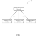
- FIG. 1 is a schematic diagram of a wireless communication system 10 according to an example of the present invention.
- the wireless communication system 10 is briefly composed of a network and a plurality of communication devices.
- the network and a communication device may communicate with each other via one or more carriers of licensed band(s) and/or unlicensed band(s).
- the network and the communication devices are simply utilized for illustrating the structure of the wireless communication system 10.
- the network may be an evolved UTRAN (E-UTRAN) including at least one evolved NB (eNB), and/or a next-generation NB (gNB), and/or at least one relay in a long term evolution (LTE) system, a LTE-Advanced (LTE-A) system or an evolution of the LTE-A system, e.g., a 5G NR system.
- E-UTRAN evolved UTRAN
- eNB evolved NB
- gNB next-generation NB
- LTE-A LTE-Advanced
- LTE-A LTE-Advanced
- 5G NR evolution of the LTE-A system
- the eNB or the relay may be termed as a base station.
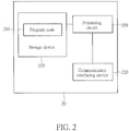
- FIG. 2 is a schematic diagram of a communication device 20 according to an example of the present invention.
- the communication device 20 can be a user equipment (UE) or the network shown in FIG. 1 , but is not limited herein.
- the communication device 20 may include a processing means 200 such as a microprocessor or an Application Specific Integrated Circuit (ASIC), a storage unit 210 and a communication interfacing unit 220.
- the storage unit 210 may be any data storage device that can store a program code 214, accessed by the processing means 200. Examples of the storage unit 210 include but are not limited to a subscriber identity module (SIM), read-only memory (ROM), flash memory, random-access memory (RAM), hard disk, and optical data storage device.
- SIM subscriber identity module
- ROM read-only memory
- RAM random-access memory
- hard disk and optical data storage device.
- the communication interfacing unit 220 is preferably a radio transceiver, and can transmit and receive wireless signals according to processing results of the processing means 200.
- a base station transmits a DL reference signal to a UE using a first transmit antenna configuration for a purpose of path loss measurement.
- the gain of the first transmit antenna configuration gain is hereinafter denoted by G t DL .
- the UE receives the DL reference signal using a first receive antenna configuration.
- the gain of the first receive antenna configuration gain is hereinafter denoted by G r DL .
- the UE transmits an UL signal to the base station using a second transmit antenna configuration and an UL power control formula.
- the gain of the second transmit antenna configuration gain is hereinafter denoted by G t UL .
- the UE uses the UL power control formula to determine an UL transmit power for the UL signal.
- the base station receives the UL signal using a second receive antenna configuration.
- the gain of the second receive antenna configuration gain is denoted by G r UL .
- An illustrative diagram is illustrated in FIG. 3 .
- the antenna configuration may comprise at least a beamforming configuration, and/or a beamformed signal configuration.
- the beamformed signal configuration may comprise a configuration of a beamformed UL reference signal or an index of a beamformed UL reference signal.
- the index of the beamformed UL reference signal may be a sounding reference signal resource index (SRI) in one embodiment.
- SRI sounding reference signal resource index
- the antenna gains in following descriptions are all represented in dB scale.
- G ⁇ t DL denote the gain of the first transmit antenna configuration in linear value.
- G t DL 10log 10 ( ⁇ ).
- the base station uses the same antenna configuration for transmitting the DL reference signal to the UE and receiving the UL signal from the UE.
- G t DL G r UL .
- the second transmit antenna configuration it is not precluded for the second transmit antenna configuration to be the same as the first receive antenna configuration.
- the UE uses the same antenna configuration for receiving the DL reference signal from the base station and transmitting the UL signal to the base station.
- G t UL G r DL .
- the UL transmit power is determined based on a closed-loop (CL) power control parameter, an open-loop power control (CL) parameter and a pass loss parameter. These parameters are associated with transmit antenna gain and receive antenna gain of the antenna configuration of the UE and the base station.
- the base station may notify the UE of the antenna configuration used for the communication by sending control information to the UE. Accordingly, the UE determines the CL power control parameter, the OL power control parameter and the pass loss parameter according to the antenna configuration, and thereby to determine the UL transmit power.
- the base station may directly determine the OL the CL power control parameter, the OL power control parameter and the pass loss parameter according to the antenna configuration, and send the control information including the determined parameters to the UE. As such, the UE determines the UL transmit power according to the parameters determined and sent by the base station.
- the base station and the UE may comprise the storage unit 210 storing the program code 214 as illustrated in FIG. 2 .
- the base station and the UE may also comprise the processing circuit 200.
- the program code 214 executed by the processing circuit 200 the UE or the base station determines the above-identified parameters. Accordingly, the UE determine the UL transmit power and have an UL transmit power control on the communication interfacing unit 220.
- the base station or the UE calculates a gain difference between the gain of the first transmit antenna configuration and the gain of the second receive antenna configuration, i.e., G t DL ⁇ G r UL .
- This calculation can be directly achieved by the base station since the base station typically determines the antenna configuration for the UE.
- this can be achieved by the UE since the UE may be notified of the antenna configuration from the control information sent by the base station.
- the base station or the UE determines a first closed-loop (CL) power control parameter for taking into account at least the above-mentioned gain difference.
- the base station or the UE performs this calculation by first assuming a unity antenna gain for both the first transmit antenna configuration and the second receive antenna configuration. Then, the base station or the UE calculates a second CL power control parameter in a way analogous to that introduced in ""Physical Layer Procedures," 3GPP TS 36.213, V14.1.0, 2017-01" for LTE/LTE-A systems, where unity antenna gain is employed. Finally, the base station or the UE obtains the first CL power control parameter by combining the gain difference of antenna gain G t DL ⁇ G r UL , and the second CL power control parameter.
- the base station will transmit the CL power control parameter to the UE using dynamic signaling in a DL control signal.
- the UE receives the DL control signal.
- the UE adjusts the UL transmit power for transmitting the UL signal following the first CL power control parameter in the DL control signal.
- the UE determines the UL power following the UL power control formula as: min ⁇ ⁇ P CMAX , c i 10 log 10 M PUSCH , c i + P O PUSCH , c j + ⁇ c j ⁇ PL c + ⁇ TF , c i + f c i + G t DL ⁇ G r UL
- P CMAX,c (i) is a transmit power limit for the UL signal taking into account other potential concurrent UL transmissions with higher priority (e.g., UL control signals)
- f c i + G t DL ⁇ G r UL is the first CL power control parameter in the DL control signal transmitted by the base station (or determined by UE itself)
- the functionalities of the rest parameters are similarly defined as in the "" Physical Layer Procedures," 3GPP TS 36.213, V14.1.0, 2017-01 ".
- the first CL power control parameter can be accumulative, which means the UE adjusts the UL power by simply adding the current UL transmit power and the first CL power control parameter transmitted from the base station (or determined by UE itself) in the dynamic DL control signal.
- the first CL power control parameter can be absolute, which means the UE negates the previous received CL power control parameter and apply the current received CL power control parameter.
- the UE may comprise different registers to record accumulated values of the first CL power control parameters with respect to different antenna configurations.
- Each register may hold an accumulated value of the first CL power control parameter with respect to a specific antenna configuration.
- the UE may read accumulated value from a different register to determine the uplink transmit power.
- the base station or the UE calculates a gain difference between the gain of the first transmit antenna configuration and the gain of the second receive antenna configuration, i. e. G t DL ⁇ G r UL .
- this calculation can be directly achieved by the base station since the base station typically determines the antenna configuration for the UE.
- this can be achieved by the UE since the UE may be notified of the antenna configuration from the control information sent by the base station.
- the base station or the UE determines a first UE-specific open-loop (OL) power control parameter for the UE taking into account at least the above-mentioned gain difference.
- the base station or the UE performs this calculation by first assuming a unity antenna gain for both the first transmit antenna configuration and the second receive antenna configuration. Then, the base station or the UE calculates a second UE-specific OL power control parameter in a way analogous to that introduced in "" Physical Layer Procedures," 3GPP TS 36.213, V14.1.0, 2017-01 " for LTE/LTE-A systems, where unity antenna gain is employed. Finally, the base station or the UE obtains the first UE-specific OL power control parameter by combining the difference of antenna gain G t DL ⁇ G r UL , and the second UE-specific OL power control parameter.
- OL open-loop
- the base station transmits the UE-specific OL power control parameter to the UE using a higher layer signaling.
- the UE receives the higher layer signaling.
- the UE adjusts the UL transmit power for transmitting the UL signal by applying the first UE-specific OL power control parameter.
- P O UE PUSCH , c j + G t DL ⁇ G r UL is the first UE-specific OL power control parameter in the higher layer signaling transmitted by the base station (or determined by UE itself), the functionalities of the rest parameters are similarly defined as in "" Physical Layer Procedures," 3GPP TS 36.213, V14.1.0, 2017-01 ".
- Both BS and UE account for antenna gain difference I
- the UE calculates a first gain difference between the gain of the second transmit antenna configuration and the gain of the first receive antenna configuration, i.e., G r DL ⁇ G t UL .
- the base station calculates a second gain difference between the gain of the first transmit antenna configuration and the gain of the second receive antenna configuration, i.e., G t DL ⁇ G r UL ,
- the base station then calculates a CL power control parameter using at least the second gain difference.
- the base station transmits the CL power control parameter to the UE using dynamic signaling in a DL control signal.
- the UE receives the DL control signal.
- the UE determines the UL power control formula using at least the first gain difference, and the CL power control parameter in the DL control signal.
- the UE determines the UL power control formula as: min ⁇ ⁇ P CMAX , c i 10 log 10 M PUSCH , c i + P O PUSCH , c j + ⁇ c j ⁇ PL c + ⁇ TF , c i + f c i + G t DL ⁇ G r UL + G r DL ⁇ G t UL where (( f ⁇ c (i)+( G ⁇ t ⁇ DL-G ⁇ r ⁇ )) is the CL power control parameter in the DL control signal transmitted by the base station, and G r DL ⁇ G t UL is the first gain difference calculated by the UE.
- the UE determines the UL transmit power for the UL signal following the UL power control formula.
- Both BS and UE account for antenna gain difference case II
- the UE calculates a first gain difference between the gain of the second transmit antenna configuration and the gain of the first receive antenna configuration, i.e. G r DL ⁇ G t UL .
- the base station calculates a second gain difference between the gain of the first transmit antenna configuration and the gain of the second receive antenna configuration, i.e. G t DL ⁇ G r UL .
- the base station then calculates a UE-specific OL power control parameter using at least the second gain difference.
- the base station transmits the UE-specific OL power control parameter to the UE using a higher layer signaling.
- the UE receives the higher layer signaling.
- the UE determines the UL power control formula using at least the first gain difference, and the UE-specific OL power control parameter in the higher layer signaling.
- the above-mentioned "UL signal” could be regular user data, UL reference signal, or UL control signal.
- the UE can also transmit a power headroom report to the base station to report the remaining available power for performing UL transmission using the UL power control formula proposed in the above descriptions.
- disclosed embodiments of the present invention provides manners to determine the uplink power control for the UE in a next generation cellular communications systems, such as 5G New Radio system.
- a next generation cellular communications systems such as 5G New Radio system.
- the disclosed embodiments of the present invention introduces calculations on transmit and receive antenna gains of the antenna configuration into the determination of the uplink transmit power control.
Landscapes
- Engineering & Computer Science (AREA)
- Signal Processing (AREA)
- Computer Networks & Wireless Communication (AREA)
- Physics & Mathematics (AREA)
- Electromagnetism (AREA)
- Mobile Radio Communication Systems (AREA)
Abstract
Description
- This application claims the benefit of
U.S. Provisional Application No. 62/475, 816, filed on Mar. 23th, 2017 - The present invention relates to transmit power control, and more particularly, to methods and apparatus for performing transmit power control in next-generation cellular communications systems, such as 5GNew Radio system.
- Path loss (PL) is the phenomenon that the electromagnetic signals attenuate when propagating from the transmitter to the receiver. The formula for path loss is widely known and can be given as:

- In cellular communication systems, uplink (UL) power control is a technique for the UEs to adjust the transmit power toward the base station in order to maintain a desired power level. The purpose of UL power control is many-fold, including the already-mentioned compensation for path loss, causing less interference to other UEs, guaranteeing a certain transmission error performance, and lowering the power consumption. In LTE/LTE-A systems, the mechanism of UL power control consists of both an open-loop (OL) component and a closed-loop (CL) component. Details of the UL power control mechanism can be found in a released document: ""Physical Layer Procedures," 3GPP TS 36.213, V14.1.0, 2017-01".
- In 5G new radio (NR) systems, it has been agreed that the UL power control mechanism also supports both an open-loop part based on path loss estimate, and a closed-loop part based on network signaling. In general, the 5G NR system reuses many of the design principles in LTE/LTE-A systems; yet at the same time introduces a few new features. Some of the features, including supporting different numerologies, different UL waveforms, and beamforming-based system access, could potentially impact the UL power control mechanism as specified for the LTE/LTE-A systems.
- Different numerologies will be supported in 5G NR systems, including different subcarrier frequency spacing, and different OFDM symbol duration. A scheduling unit is defined as the smallest time frequency resource used for scheduling one DL or one UL transmission for a UE. The number of resource elements in a scheduling unit is expected to be the same across different numerologies. Both discrete Fourier transform (DFT)-spread OFDM and cyclic prefix (CP) -OFDM for UL transmissions are both supported in 5G NR systems.
- Carrier frequencies range from several MHz to as high as 60 GHz will be supported in 5G NR systems. As can be observed in the path loss formula, the path loss worsens along with decreasing wavelength, or equivalently, with increasing carrier frequency. It thus follows that for 5G NR systems deployed in the frequency range close to 60 GHz, the effect of path loss is a big challenge to the system design. Antenna arrays that achieves a high transmit antenna gain as well as a high receive antenna gain, or the beamforming gain, have been proposed to be supported in the 5G NR systems as a building block right from the beginning. This implies that the fundamental system information as well as cell-specific reference signals are all transmitted using beamformed signals with antenna gains larger than 1, for both DL and UL directions.
- It is one objective of the present invention to provide methods and apparatus for determine and performing uplink power control in next-generation cellular communications systems, such as 5G New Radio system. Since the next-generation cellular adopts the beamforming technology, embodiments of the present invention relies on calculations on antenna gains of antenna configuration to determine the uplink transmit power.
- According to one embodiment, a method for a user equipment (UE) to perform uplink transmit power control is provided. The UE comprises: receiving, from a base station, a control information comprising at least an antenna configuration; determining uplink transmit power of at least one uplink signal based on at least the control information; and transmitting the at least one uplink signal with the determined uplink transmit power to the base station.
- According to one embodiment, a user equipment (UE) is provided. The UE comprises: a communication interfacing unit; a storage unit and a processing circuit. The communication interfacing unit is arranged to receive, from a base station, a control information comprising at least an antenna configuration. The storage unit is arranged to store program code. The processing circuit is arranged to execute the program code thereby to perform steps of determining uplink transmit power of at least one uplink signal based on at least the control information, wherein the communication interfacing unit is arranged to transmit the at least one uplink signal with the determined uplink transmit power to the base station.
- These and other objectives of the present invention will no doubt become obvious to those of ordinary skill in the art after reading the following detailed description of the preferred embodiment that is illustrated in the various figures and drawings.
-
-
FIG. 1 is a schematic diagram of awireless communication system 10 according to an embodiment of the present invention. -
FIG. 2 is a schematic diagram of acommunication device 20 according to one embodiment of the present invention. -
FIG. 3 illustrates gains of antenna configurations of UE and base station in uplink and downlink transmission. -
FIG. 1 is a schematic diagram of awireless communication system 10 according to an example of the present invention. Thewireless communication system 10 is briefly composed of a network and a plurality of communication devices. The network and a communication device may communicate with each other via one or more carriers of licensed band(s) and/or unlicensed band(s). InFIG. 1 , the network and the communication devices are simply utilized for illustrating the structure of thewireless communication system 10. Practically, the network may be an evolved UTRAN (E-UTRAN) including at least one evolved NB (eNB), and/or a next-generation NB (gNB), and/or at least one relay in a long term evolution (LTE) system, a LTE-Advanced (LTE-A) system or an evolution of the LTE-A system, e.g., a 5G NR system. The eNB or the relay may be termed as a base station. -
FIG. 2 is a schematic diagram of acommunication device 20 according to an example of the present invention. Thecommunication device 20 can be a user equipment (UE) or the network shown inFIG. 1 , but is not limited herein. Thecommunication device 20 may include a processing means 200 such as a microprocessor or an Application Specific Integrated Circuit (ASIC), astorage unit 210 and acommunication interfacing unit 220. Thestorage unit 210 may be any data storage device that can store aprogram code 214, accessed by the processing means 200. Examples of thestorage unit 210 include but are not limited to a subscriber identity module (SIM), read-only memory (ROM), flash memory, random-access memory (RAM), hard disk, and optical data storage device. Thecommunication interfacing unit 220 is preferably a radio transceiver, and can transmit and receive wireless signals according to processing results of the processing means 200. Theprogram code 214 implementing any of solutions above may be stored in thestorage unit 210 and executed in the processing means 200. - To determine the transmit power, a base station transmits a DL reference signal to a UE using a first transmit antenna configuration for a purpose of path loss measurement. The gain of the first transmit antenna configuration gain is hereinafter denoted by


FIG. 3 . Specifically, the antenna configuration may comprise at least a beamforming configuration, and/or a beamformed signal configuration. In one embodiment, the beamformed signal configuration may comprise a configuration of a beamformed UL reference signal or an index of a beamformed UL reference signal. Furthermore, the index of the beamformed UL reference signal may be a sounding reference signal resource index (SRI) in one embodiment. - The antenna gains in following descriptions are all represented in dB scale. For example, let

 (Ĝ
(Ĝ ). Note that it is not precluded for the first transmit antenna configuration to be the same as the second receive antenna configuration. In other words, the base station uses the same antenna configuration for transmitting the DL reference signal to the UE and receiving the UL signal from the UE. And in this case we have


- The UL transmit power is determined based on a closed-loop (CL) power control parameter, an open-loop power control (CL) parameter and a pass loss parameter. These parameters are associated with transmit antenna gain and receive antenna gain of the antenna configuration of the UE and the base station. During the communication, the base station may notify the UE of the antenna configuration used for the communication by sending control information to the UE. Accordingly, the UE determines the CL power control parameter, the OL power control parameter and the pass loss parameter according to the antenna configuration, and thereby to determine the UL transmit power. Alternatively, the base station may directly determine the OL the CL power control parameter, the OL power control parameter and the pass loss parameter according to the antenna configuration, and send the control information including the determined parameters to the UE. As such, the UE determines the UL transmit power according to the parameters determined and sent by the base station.
- As mentioned above, the base station and the UE may comprise the
storage unit 210 storing theprogram code 214 as illustrated inFIG. 2 . The base station and the UE may also comprise theprocessing circuit 200. When theprogram code 214 executed by theprocessing circuit 200, the UE or the base station determines the above-identified parameters. Accordingly, the UE determine the UL transmit power and have an UL transmit power control on thecommunication interfacing unit 220. - In one embodiment, the base station or the UE calculates a gain difference between the gain of the first transmit antenna configuration and the gain of the second receive antenna configuration, i.e.,

- The base station or the UE determines a first closed-loop (CL) power control parameter for taking into account at least the above-mentioned gain difference. In one embodiment, the base station or the UE performs this calculation by first assuming a unity antenna gain for both the first transmit antenna configuration and the second receive antenna configuration. Then, the base station or the UE calculates a second CL power control parameter in a way analogous to that introduced in ""Physical Layer Procedures," 3GPP TS 36.213, V14.1.0, 2017-01" for LTE/LTE-A systems, where unity antenna gain is employed. Finally, the base station or the UE obtains the first CL power control parameter by combining the gain difference of antenna gain

- If the CL power control parameter is determined by the base station, the base station will transmit the CL power control parameter to the UE using dynamic signaling in a DL control signal. The UE receives the DL control signal. The UE adjusts the UL transmit power for transmitting the UL signal following the first CL power control parameter in the DL control signal. In one embodiment, the UE determines the UL power following the UL power control formula as:


- The first CL power control parameter can be accumulative, which means the UE adjusts the UL power by simply adding the current UL transmit power and the first CL power control parameter transmitted from the base station (or determined by UE itself) in the dynamic DL control signal. Alternatively, the first CL power control parameter can be absolute, which means the UE negates the previous received CL power control parameter and apply the current received CL power control parameter.
- In one embodiment, the UE may comprise different registers to record accumulated values of the first CL power control parameters with respect to different antenna configurations. Each register may hold an accumulated value of the first CL power control parameter with respect to a specific antenna configuration. When the antenna configuration changes, the UE may read accumulated value from a different register to determine the uplink transmit power.
- In one embodiment, the base station or the UE calculates a gain difference between the gain of the first transmit antenna configuration and the gain of the second receive antenna configuration, i. e.

- The base station or the UE determines a first UE-specific open-loop (OL) power control parameter for the UE taking into account at least the above-mentioned gain difference. In one embodiment, the base station or the UE performs this calculation by first assuming a unity antenna gain for both the first transmit antenna configuration and the second receive antenna configuration. Then, the base station or the UE calculates a second UE-specific OL power control parameter in a way analogous to that introduced in ""Physical Layer Procedures," 3GPP TS 36.213, V14.1.0, 2017-01" for LTE/LTE-A systems, where unity antenna gain is employed. Finally, the base station or the UE obtains the first UE-specific OL power control parameter by combining the difference of antenna gain

- If the OL power control parameter is determined by the base station, the base station transmits the UE-specific OL power control parameter to the UE using a higher layer signaling. The UE receives the higher layer signaling. The UE adjusts the UL transmit power for transmitting the UL signal by applying the first UE-specific OL power control parameter. In one embodiment, the UE determines the UL power following the UL power control formula as:


- In one embodiment, the UE calculates a first gain difference between the gain of the second transmit antenna configuration and the gain of the first receive antenna configuration, i.e.,


- In one embodiment, the UE calculates a first gain difference between the gain of the second transmit antenna configuration and the gain of the first receive antenna configuration, i.e.


- According to various embodiment of the present invention, the above-mentioned "UL signal" could be regular user data, UL reference signal, or UL control signal. In additionally, The UE can also transmit a power headroom report to the base station to report the remaining available power for performing UL transmission using the UL power control formula proposed in the above descriptions.
- In summary, disclosed embodiments of the present invention provides manners to determine the uplink power control for the UE in a next generation cellular communications systems, such as 5G New Radio system. As the next generation cellular communications systems uses adopts the beamforming technology, the disclosed embodiments of the present invention introduces calculations on transmit and receive antenna gains of the antenna configuration into the determination of the uplink transmit power control.
Claims (15)
- A method for a user equipment (UE) to perform uplink transmit power control, comprising:receiving, from a base station, a control information comprising at least an antenna configuration;determining uplink transmit power of at least one uplink signal based on at least the control information; and transmitting the at least one uplink signal with the determined uplink transmit power to the base station.
- The method of claim 1, further comprising:receiving a downlink reference signal from the base station for path loss measurement based on the antenna configuration; anddetermining the uplink transmit power of the at least one uplink signal based on at least the control information and the path loss measurement.
- The method of claim 1, wherein the antenna configuration comprises at least a beamforming configuration, and/or a beamformed signal configuration.
- The method of claim 3, wherein the beamformed signal configuration comprises a configuration of a beamformed UL reference signal or an index of a beamformed UL reference signal.
- The method of claim 4, wherein the index of the beamformed UL reference signal is a sounding reference signal resource index (SRI).
- A user equipment (UE), comprising:a communication interfacing unit, arranged to receive, from a base station, a control information comprising at least an antenna configuration;a storage unit, arranged to store program code; anda processing circuit, arranged to execute the program code thereby to perform steps of determining uplink transmit power of at least one uplink signal based on at least the control information, wherein the communication interfacing unit is arranged to transmit the at least one uplink signal with the determined uplink transmit power to the base station.
- The UE of claim 6, wherein the communication interfacing unit is further arranged to receive a downlink reference signal from the base station for path loss measurement based on the antenna configuration; and the processing circuit is arranged to execute the program code thereby to further determine the uplink transmit power of the at least one uplink signal based on at least the control information and the path loss measurement.
- The UE of claim 6, wherein the antenna configuration comprises at least a beamforming configuration, and/or a beamformed signal configuration;
- The UE of claim 8, wherein the beamformed signal configuration comprises a configuration of a beamformed UL reference signal or an index of a beamformed UL reference signal.
- The UE of claim 9, wherein the index of the beamformed UL reference signal is a sounding reference signal resource index (SRI).
- The UE of claim 6, wherein the processing circuit is arranged to execute the program code thereby further to perform at least one step of:determining a closed-loop (CL) power control parameter according to the antenna configuration;determining an open-loop (OL) power control parameter according to the antenna configuration; anddetermining a pass loss parameter according to the antenna configuration.
- The UE of claim 11, wherein the processing circuit is arranged to execute the program code thereby further to perform steps of:calculating a gain difference between a transmit antenna gain and a receive antenna gain of the base station according to the antenna configuration;determining a second CL power control parameter by assuming the transmit antenna gain and the receive antenna gain of the base station as unity; andcombining the gain difference between the transmit antenna gain and the receive antenna gain of the base station and the second CL power control parameter thereby to obtain a first CL power control parameter.
- The UE of claim 12, wherein the processing circuit is arranged to execute the program code thereby to further perform steps of:determining a gain difference between a receive antenna gain and a transmit antenna gain of the UE according to the antenna configuration; anddetermining the transmit power according to the determined CL power parameter and the gain difference between the receive antenna gain and the transmit antenna gain of the UE.
- The UE of claim 12, wherein the processing circuit is arranged to execute the program code thereby to further perform steps of:calculating a gain difference between a transmit antenna gain and a receive antenna gain of the base station according to the antenna configuration;determining a second UE-specific OL power control parameter by assuming the transmit antenna gain and the receive antenna gain of the base station as unity; andcombining the gain difference between the transmit antenna gain and the receive antenna gain of the base station and the second UE-specific OL power control parameter thereby to obtain a first UE-specific OL power control parameter.
- The UE of claim 14, wherein the processing circuit is arranged to execute the program code thereby to further perform steps of:determining a gain difference between a receive antenna gain and a transmit antenna gain of the UE according to the antenna configuration; anddetermining the uplink transmit power according to the determined OL power control parameter and the gain difference between the receive antenna gain and the transmit antenna gain of the UE.
Applications Claiming Priority (2)
| Application Number | Priority Date | Filing Date | Title |
|---|---|---|---|
| US201762475816P | 2017-03-23 | 2017-03-23 | |
| US15/871,089 US10321412B2 (en) | 2017-03-23 | 2018-01-15 | Uplink power control using beamforming to compensate for path loss |
Publications (1)
| Publication Number | Publication Date |
|---|---|
| EP3379740A1 true EP3379740A1 (en) | 2018-09-26 |
Family
ID=61027470
Family Applications (1)
| Application Number | Title | Priority Date | Filing Date |
|---|---|---|---|
| EP18152900.9A Withdrawn EP3379740A1 (en) | 2017-03-23 | 2018-01-23 | Methods and apparatus for transmit power control |
Country Status (4)
| Country | Link |
|---|---|
| US (2) | US10321412B2 (en) |
| EP (1) | EP3379740A1 (en) |
| CN (1) | CN108712776A (en) |
| TW (1) | TWI655873B (en) |
Cited By (1)
| Publication number | Priority date | Publication date | Assignee | Title |
|---|---|---|---|---|
| CN116801366A (en) * | 2023-07-27 | 2023-09-22 | 上海移远通信技术股份有限公司 | Power compensation methods, V2X systems, vehicles and storage media |
Families Citing this family (10)
| Publication number | Priority date | Publication date | Assignee | Title |
|---|---|---|---|---|
| US10321412B2 (en) * | 2017-03-23 | 2019-06-11 | Htc Corporation | Uplink power control using beamforming to compensate for path loss |
| US10425901B2 (en) * | 2017-06-26 | 2019-09-24 | Qualcomm Incorporated | Uplink transmit power control during random access procedures |
| US12294952B2 (en) * | 2018-05-17 | 2025-05-06 | Qualcomm Incorporated | Transmission power configuration |
| WO2019231823A1 (en) | 2018-05-29 | 2019-12-05 | Skyworks Solutions, Inc. | Beamforming communication systems with power control based on antenna pattern configuration |
| CN110535580B (en) * | 2018-08-08 | 2022-08-23 | 中兴通讯股份有限公司 | Transmission control method, sounding reference signal transmission method, terminal, base station, and medium |
| US11588560B2 (en) * | 2020-02-21 | 2023-02-21 | Qualcomm Incorporated | Adaptation of transmit and receive antennas |
| CN115362717B (en) * | 2020-04-08 | 2025-11-18 | 苹果公司 | Path loss reference signal management |
| US11924006B2 (en) * | 2021-11-17 | 2024-03-05 | T-Mobile Innovations Llc | Enhanced method to do channel estimation in a multiple input multiple output based cellular radio technology by leveraging radio power reception level at per antenna element |
| CN117545072A (en) * | 2022-07-29 | 2024-02-09 | 华为技术有限公司 | Method and communication device for calculating uplink transmission power |
| WO2024092761A1 (en) * | 2022-11-04 | 2024-05-10 | Apple Inc. | Enhancement on open loop power control for atg ues |
Citations (3)
| Publication number | Priority date | Publication date | Assignee | Title |
|---|---|---|---|---|
| US20080227477A1 (en) * | 2007-03-13 | 2008-09-18 | Qualcomm Incorporated | Power control method and apparatus |
| US20140185481A1 (en) * | 2012-12-27 | 2014-07-03 | Samsung Electronics Co., Ltd. | Uplink power control method and apparatus in a beam-forming based wireless communication system |
| US20160205633A1 (en) * | 2013-09-30 | 2016-07-14 | Sony Corporation | Communication control apparatus, communication control method, terminal apparatus, and information processing apparatus |
Family Cites Families (8)
| Publication number | Priority date | Publication date | Assignee | Title |
|---|---|---|---|---|
| JP5990815B2 (en) * | 2011-11-07 | 2016-09-14 | シャープ株式会社 | Base station, terminal, communication system and communication method |
| US8841460B2 (en) * | 2011-12-16 | 2014-09-23 | State Of Oregon Acting By And Through The State Board Of Higher Education On Behalf Of The University Of Oregon | Tunable phenylacetylene hosts |
| EP2989838B1 (en) * | 2013-04-23 | 2021-01-13 | Samsung Electronics Co., Ltd. | Method and apparatus for controlling power of uplink in a beam forming system |
| WO2015060680A2 (en) * | 2013-10-24 | 2015-04-30 | 엘지전자 주식회사 | Method for reporting channel state information in wireless communication system and apparatus therefor |
| KR102272272B1 (en) * | 2014-07-11 | 2021-07-02 | 삼성에스디아이 주식회사 | Electrolyte for rechargeable lithium battery and rechargeable lithium battery including the same |
| JP2016025450A (en) * | 2014-07-18 | 2016-02-08 | 富士ゼロックス株式会社 | Information processing system, information processing device, mobile terminal device and program |
| US10014916B2 (en) * | 2014-11-10 | 2018-07-03 | Samsung Electronics Co., Ltd. | 2D active antenna array operation for wireless communication systems |
| US10321412B2 (en) * | 2017-03-23 | 2019-06-11 | Htc Corporation | Uplink power control using beamforming to compensate for path loss |
-
2018
- 2018-01-15 US US15/871,089 patent/US10321412B2/en active Active
- 2018-01-23 EP EP18152900.9A patent/EP3379740A1/en not_active Withdrawn
- 2018-03-20 TW TW107109454A patent/TWI655873B/en active
- 2018-03-23 CN CN201810243769.4A patent/CN108712776A/en active Pending
-
2019
- 2019-04-28 US US16/396,759 patent/US10499344B2/en active Active
Patent Citations (3)
| Publication number | Priority date | Publication date | Assignee | Title |
|---|---|---|---|---|
| US20080227477A1 (en) * | 2007-03-13 | 2008-09-18 | Qualcomm Incorporated | Power control method and apparatus |
| US20140185481A1 (en) * | 2012-12-27 | 2014-07-03 | Samsung Electronics Co., Ltd. | Uplink power control method and apparatus in a beam-forming based wireless communication system |
| US20160205633A1 (en) * | 2013-09-30 | 2016-07-14 | Sony Corporation | Communication control apparatus, communication control method, terminal apparatus, and information processing apparatus |
Non-Patent Citations (2)
| Title |
|---|
| "Physical Layer Procedures", 3GPP TS 36. 213, January 2017 (2017-01-01) |
| "Physical Layer Procedures", 3GPP TS 36.213, January 2017 (2017-01-01) |
Cited By (1)
| Publication number | Priority date | Publication date | Assignee | Title |
|---|---|---|---|---|
| CN116801366A (en) * | 2023-07-27 | 2023-09-22 | 上海移远通信技术股份有限公司 | Power compensation methods, V2X systems, vehicles and storage media |
Also Published As
| Publication number | Publication date |
|---|---|
| TW201836405A (en) | 2018-10-01 |
| US20190253979A1 (en) | 2019-08-15 |
| US10499344B2 (en) | 2019-12-03 |
| CN108712776A (en) | 2018-10-26 |
| US10321412B2 (en) | 2019-06-11 |
| US20180279231A1 (en) | 2018-09-27 |
| TWI655873B (en) | 2019-04-01 |
Similar Documents
| Publication | Publication Date | Title |
|---|---|---|
| US10499344B2 (en) | Uplink power control using beamforming to compensate for path loss | |
| EP3800946B1 (en) | Methods and apparatuses for multi-panel power control | |
| EP3619976B1 (en) | Power control framework for multi-beam configuration | |
| EP3824567B1 (en) | Transmission of csi report to base station for eirp-constrained transmissions | |
| US8929232B2 (en) | Transmission power control method and mobile station apparatus | |
| EP3484214B1 (en) | Method, apparatus and equipment for controlling uplink transmission power and storage medium | |
| EP3535867B1 (en) | Communication methods and devices for uplink power control | |
| EP3826376B1 (en) | Method and device for controlling uplink power | |
| EP4093099A1 (en) | Sounding reference signal power control for multiple input multiple output wireless system | |
| US8626069B2 (en) | Apparatus and method for beamforming considering interference amount in broadband wireless communication system | |
| EP2849504A1 (en) | Terminal, communication method, and integrated circuit | |
| US20170026102A1 (en) | Method for mixedly indicating uplink and downlink beams, base station, terminal and system | |
| US11044744B2 (en) | Method for transmitting and receiving downlink control signalling, apparatus, base station and terminal | |
| KR20210042847A (en) | Power control method and device, and method and device for determining target received power | |
| EP3637934B1 (en) | Method and apparatus for use in resource configuration | |
| EP3503659B1 (en) | Sounding reference signal sending method and user equipment | |
| EP2747495A1 (en) | Compensation method, base station, and user equipment for uplink power control in a comp system | |
| EP3294015B1 (en) | Method and device for acquiring uplink synchronism in consideration of beam forming effect in wireless communication system | |
| US11777691B2 (en) | System and method for reporting signal quality information | |
| KR102319369B1 (en) | Apparatus and method for managing interference in wireless communication system | |
| CN109951264B (en) | Method, apparatus and computer readable medium for communication | |
| CN113454921B (en) | Method and system for adapting beamwidth of a beam on a NR physical channel | |
| EP3723426A1 (en) | Communication method and system | |
| US20200008243A1 (en) | Preamble signal detection method in wireless communication system and device therefor | |
| US20230337141A1 (en) | Method and device for uplink power control, and storage medium |
Legal Events
| Date | Code | Title | Description |
|---|---|---|---|
| PUAI | Public reference made under article 153(3) epc to a published international application that has entered the european phase |
Free format text: ORIGINAL CODE: 0009012 |
|
| 17P | Request for examination filed |
Effective date: 20180123 |
|
| AK | Designated contracting states |
Kind code of ref document: A1 Designated state(s): AL AT BE BG CH CY CZ DE DK EE ES FI FR GB GR HR HU IE IS IT LI LT LU LV MC MK MT NL NO PL PT RO RS SE SI SK SM TR |
|
| AX | Request for extension of the european patent |
Extension state: BA ME |
|
| RBV | Designated contracting states (corrected) |
Designated state(s): AL AT BE BG CH CY CZ DE DK EE ES FI FR GB GR HR HU IE IS IT LI LT LU LV MC MK MT NL NO PL PT RO RS SE SI SK SM TR |
|
| STAA | Information on the status of an ep patent application or granted ep patent |
Free format text: STATUS: THE APPLICATION IS DEEMED TO BE WITHDRAWN |
|
| 18D | Application deemed to be withdrawn |
Effective date: 20200718 |