EP3379664A1 - A laser and method of controlling a laser to output a signal intermittently - Google Patents
A laser and method of controlling a laser to output a signal intermittently Download PDFInfo
- Publication number
- EP3379664A1 EP3379664A1 EP17305301.8A EP17305301A EP3379664A1 EP 3379664 A1 EP3379664 A1 EP 3379664A1 EP 17305301 A EP17305301 A EP 17305301A EP 3379664 A1 EP3379664 A1 EP 3379664A1
- Authority
- EP
- European Patent Office
- Prior art keywords
- laser
- section
- optical
- optical loss
- signal
- Prior art date
- Legal status (The legal status is an assumption and is not a legal conclusion. Google has not performed a legal analysis and makes no representation as to the accuracy of the status listed.)
- Granted
Links
Images

Classifications
-
- H—ELECTRICITY
- H01—ELECTRIC ELEMENTS
- H01S—DEVICES USING THE PROCESS OF LIGHT AMPLIFICATION BY STIMULATED EMISSION OF RADIATION [LASER] TO AMPLIFY OR GENERATE LIGHT; DEVICES USING STIMULATED EMISSION OF ELECTROMAGNETIC RADIATION IN WAVE RANGES OTHER THAN OPTICAL
- H01S5/00—Semiconductor lasers
- H01S5/10—Construction or shape of the optical resonator, e.g. extended or external cavity, coupled cavities, bent-guide, varying width, thickness or composition of the active region
- H01S5/14—External cavity lasers
- H01S5/141—External cavity lasers using a wavelength selective device, e.g. a grating or etalon
-
- H—ELECTRICITY
- H01—ELECTRIC ELEMENTS
- H01S—DEVICES USING THE PROCESS OF LIGHT AMPLIFICATION BY STIMULATED EMISSION OF RADIATION [LASER] TO AMPLIFY OR GENERATE LIGHT; DEVICES USING STIMULATED EMISSION OF ELECTROMAGNETIC RADIATION IN WAVE RANGES OTHER THAN OPTICAL
- H01S5/00—Semiconductor lasers
- H01S5/06—Arrangements for controlling the laser output parameters, e.g. by operating on the active medium
- H01S5/062—Arrangements for controlling the laser output parameters, e.g. by operating on the active medium by varying the potential of the electrodes
- H01S5/0625—Arrangements for controlling the laser output parameters, e.g. by operating on the active medium by varying the potential of the electrodes in multi-section lasers
- H01S5/06253—Pulse modulation
-
- H—ELECTRICITY
- H01—ELECTRIC ELEMENTS
- H01S—DEVICES USING THE PROCESS OF LIGHT AMPLIFICATION BY STIMULATED EMISSION OF RADIATION [LASER] TO AMPLIFY OR GENERATE LIGHT; DEVICES USING STIMULATED EMISSION OF ELECTROMAGNETIC RADIATION IN WAVE RANGES OTHER THAN OPTICAL
- H01S3/00—Lasers, i.e. devices using stimulated emission of electromagnetic radiation in the infrared, visible or ultraviolet wave range
- H01S3/10—Controlling the intensity, frequency, phase, polarisation or direction of the emitted radiation, e.g. switching, gating, modulating or demodulating
- H01S3/10038—Amplitude control
-
- H—ELECTRICITY
- H01—ELECTRIC ELEMENTS
- H01S—DEVICES USING THE PROCESS OF LIGHT AMPLIFICATION BY STIMULATED EMISSION OF RADIATION [LASER] TO AMPLIFY OR GENERATE LIGHT; DEVICES USING STIMULATED EMISSION OF ELECTROMAGNETIC RADIATION IN WAVE RANGES OTHER THAN OPTICAL
- H01S3/00—Lasers, i.e. devices using stimulated emission of electromagnetic radiation in the infrared, visible or ultraviolet wave range
- H01S3/10—Controlling the intensity, frequency, phase, polarisation or direction of the emitted radiation, e.g. switching, gating, modulating or demodulating
- H01S3/105—Controlling the intensity, frequency, phase, polarisation or direction of the emitted radiation, e.g. switching, gating, modulating or demodulating by controlling the mutual position or the reflecting properties of the reflectors of the cavity, e.g. by controlling the cavity length
-
- H—ELECTRICITY
- H01—ELECTRIC ELEMENTS
- H01S—DEVICES USING THE PROCESS OF LIGHT AMPLIFICATION BY STIMULATED EMISSION OF RADIATION [LASER] TO AMPLIFY OR GENERATE LIGHT; DEVICES USING STIMULATED EMISSION OF ELECTROMAGNETIC RADIATION IN WAVE RANGES OTHER THAN OPTICAL
- H01S5/00—Semiconductor lasers
- H01S5/02—Structural details or components not essential to laser action
- H01S5/028—Coatings ; Treatment of the laser facets, e.g. etching, passivation layers or reflecting layers
- H01S5/0287—Facet reflectivity
-
- H—ELECTRICITY
- H01—ELECTRIC ELEMENTS
- H01S—DEVICES USING THE PROCESS OF LIGHT AMPLIFICATION BY STIMULATED EMISSION OF RADIATION [LASER] TO AMPLIFY OR GENERATE LIGHT; DEVICES USING STIMULATED EMISSION OF ELECTROMAGNETIC RADIATION IN WAVE RANGES OTHER THAN OPTICAL
- H01S5/00—Semiconductor lasers
- H01S5/06—Arrangements for controlling the laser output parameters, e.g. by operating on the active medium
- H01S5/062—Arrangements for controlling the laser output parameters, e.g. by operating on the active medium by varying the potential of the electrodes
- H01S5/0625—Arrangements for controlling the laser output parameters, e.g. by operating on the active medium by varying the potential of the electrodes in multi-section lasers
- H01S5/06255—Controlling the frequency of the radiation
- H01S5/06256—Controlling the frequency of the radiation with DBR-structure
-
- H—ELECTRICITY
- H01—ELECTRIC ELEMENTS
- H01S—DEVICES USING THE PROCESS OF LIGHT AMPLIFICATION BY STIMULATED EMISSION OF RADIATION [LASER] TO AMPLIFY OR GENERATE LIGHT; DEVICES USING STIMULATED EMISSION OF ELECTROMAGNETIC RADIATION IN WAVE RANGES OTHER THAN OPTICAL
- H01S5/00—Semiconductor lasers
- H01S5/06—Arrangements for controlling the laser output parameters, e.g. by operating on the active medium
- H01S5/062—Arrangements for controlling the laser output parameters, e.g. by operating on the active medium by varying the potential of the electrodes
- H01S5/0625—Arrangements for controlling the laser output parameters, e.g. by operating on the active medium by varying the potential of the electrodes in multi-section lasers
- H01S5/06255—Controlling the frequency of the radiation
- H01S5/06258—Controlling the frequency of the radiation with DFB-structure
Definitions
- the field of the invention relates to lasers and in particular to lasers configured to intermittently output signals.
- Emerging NGPON2 systems use both time and wavelength division multiplexing (TWDM) when transmitting signals.
- TWDM wavelength division multiplexing
- the time division multiplexing is generated by operating multiple distributed feedback (DFB) laser sources in burst mode, such that each laser only transmits signals during its own time period.
- DFB distributed feedback
- One problem with operating in burst mode particularly in systems which also use wavelength division multiplexing is the drift in wavelength that can occur due to temperature changes in the laser during the bursts.
- the driving current driving the laser during the bursts will provide some heating to the laser which can cause wavelength drift.
- Lasers for example, which use a Bragg grating to define the wavelength are particularly susceptible to changes in the effective index resulting in changes in the wavelength due to temperature changes.
- Wavelength division multiplexing systems need to be able to separate the different signals and use wavelength selective elements such as arrayed wavelength gratings AWG to do this. Where wavelengths get misaligned with the AWG transmission spectrum a first effect is a reduction in output power and a further effect is the pollution of adjacent channels. In this regard for NGPON2 applications with 100GHZ or 50GHz spaced channels, any wavelength drift should remain below 20GHz for 100GHz spacing or 10GHz for 50 GHz spacing.
- Counter heating consists in using a heater along the laser waveguide and applying a voltage to the heater in antiphase to the bursts such that the heat generated around the laser is maintained at a fairly constant level over time leading to a reduction in wavelength drift.
- a first aspect of the present invention provides a laser, said laser comprising:
- the inventors of the present invention recognised that the generation of a laser signal from a laser requires the gain experienced by the optical signal within the laser cavity due to amplification in the active or gain section to exceed the losses that are experienced by the signal as it is reflected between the end cavity surfaces. In effect there is a threshold at which the cumulative gain and loss is sufficient for lasing effects and below which no lasing effects occur.
- lasers have been controlled to operate intermittently, such as in burst mode, by providing intermittent amplification of the optical signal with an intermittent driving signal.
- this driving signal is sufficient to amplify the signal enough such that the gains experienced by the optical signal in the resonant cavity exceed the threshold value required for lasing then the laser is turned on, when the driving signal drops below this the laser turns off.
- the inventors of the present invention recognised that an alternative way of controlling the intermittent operation of a laser without needing to change the driving signal would be to change the losses experienced by the optical signal within the resonant cavity.
- An advantage of this is that the driving signal supplies power to the laser and it is this that may cause the laser to heat up. Where the driving signal is intermittent then the heating is intermittent and the laser experiences temperature changes. These changes in temperature can be disadvantageous causing changes in the output wavelength of the laser.
- the lasing cavity were to be provided with a controllable optical loss section the losses experienced by the optical signal within the resonant cavity could be controlled and where they were increased to above the gains experienced by the optical signal due to amplification by a driving signal, then lasing effects would be supressed and the laser would no longer output an optical signal. In this way a signal can be output or not in dependence upon the state of the optical loss section rather than on the level of a driving signal.
- changes in optical losses that take the signal either above or below the threshold are all that is required to effectively turn the output signal off and on, thereby providing a controllable laser whose operation temperature is substantially independent of whether it is currently outputting a signal.
- the optical signal output by the laser may be a simple unmodulated laser signal or it may be a modulated optical signal comprising information encoded within the modulations.
- the laser may be formed in a number of different ways, in some embodiments the laser comprises a semiconductor laser.
- Semiconductor lasers comprise active sections formed of an active material that amplifies optical signals in response to a driving current. They are susceptible to heating due to that driving current and where they are operating in an intermittent mode such as a burst mode and this heating is intermittent, they may experience problems such as wavelength or frequency drift. Thus, they are particularly applicable to improvements provided by embodiments of the invention.
- the controllable loss section may be formed in a number of ways such as by a moveable mirror forming one reflecting surface of the optical cavity and operable to move between a position where the light is reflected back to the other end of the cavity and a position where it is deflected from the return path. Alternatively it may be formed by some form of a movable shield operable to intercept the beams reflecting between the surfaces.
- said controllable optical loss section comprises an absorbing section, said absorbing section being configured to absorb optical energy of a wavelength of said optical signal when in said high optical loss mode and to transmit optical energy of said wavelength of said optical signal when in said lower optical loss mode.
- One embodiment provides a laser configured to output an optical signal, said laser comprising: a resonant cavity; said resonant cavity comprising a laser section comprising an active material operable to amplify said optical signal in response to a driving current and a controllable absorbing section, said controllable absorbing section being configured to absorb optical energy of a wavelength of said optical signal when in absorbing mode and to transmit optical energy of said wavelength of said optical signal when in transmitting mode; and a control signal input operable to supply a control signal to said absorbing section to control said absorbing section to periodically transition between said absorbing and transmitting modes, a lasing effect of said resonant cavity being suppressed by absorption of said optical energy when said absorbing section is in said absorbing mode, such that said transitioning of modes of said absorbing section causes said laser to periodically output said optical signal.
- One effective way of controlling the optical losses is to provide the laser cavity with an absorbing section.
- An absorbing section that is controllable to operate in either an absorbing mode in which it absorbs optical energy of the optical signal or a transmitting mode in which it transmits or even amplifies the optical signal can be used to provide effective control of the losses.
- said absorbing section comprises a semiconductor optical amplifier, said semiconductor optical amplifier being configured to switch between absorbing mode and transparent mode in response to said control signal.
- the absorbing section can be formed in a number of ways provided that it is controllable to switch between an absorbing mode where sufficient optical energy is absorbed to suppress the lasing effect and a lower loss transparent mode, in some cases a semiconductor optical amplifier is used. These are compatible with many semiconductor lasers and can be simply integrated into the resonant cavity, providing effective, simple and power efficient control of the lasing effect within the cavity. In this regard their absorption properties are good such that a relatively small portion of the optical cavity will be sufficient to provide an absorbing section operable to provide the desired effects.
- said absorbing section is formed of a same material as said material of said active section, said absorbing section being reverse biased when in absorbing mode.
- a semiconductor optical amplifier may advantageously be formed of the same material as the active section of the laser. Reverse biasing this section makes the section act to absorb optical signals of the wavelength that would otherwise be transmitted or even amplified by the device. Forming it of the same material in this way makes its manufacture and control straightforward and provides an absorbing section that operates at the wavelengths of the optical signal amplified in the resonant cavity.
- the absorbing section simply needs to be able to transmit the signal when not in absorbing mode, in some embodiments, it is configured to amplify the optical signal when in transmitting mode.
- a semiconductor optical amplifier as the absorbing section also provides the possibility of providing amplification of the transmitted signal when in lower loss mode. This amplification requires a forward biased voltage to provide a driving current, and thus, whether or not amplification is provided can be selected in dependence upon the requirements, power consumption and output signal level, of the laser.
- said laser further comprises an electrically insulating section, said active section and said absorbing section being separated by said electrically insulating section such that an electrical signal input to one of said laser or absorbing section is insulated from the other section.
- an insulating section between the two sections can be provided. This can be done by simple implantation of for example H + ions into the semiconductor material between the two sections to nullify the dopant, alternatively the insulation section may be provided using etching to provide the electrical isolation.
- said laser comprises driving current control circuitry for controlling said driving current supplied to said at least one active section such that an average electrical power supplied to said at least one active section is substantially the same during a period when said laser is not emitting said output signal and during a period when said laser is emitting said output signal.
- One advantage of controlling the output of the laser using control of the absorption section is that the power supplied to the laser maybe maintained at a constant average level even where the output of the laser is intermittent.
- the output optical signal is sensitive to temperature variations, these causing variations in the wavelength output. This can be a particular problem where a laser is being used in a time division and wavelength division multiplexed system, where individual lasers are used to output signals in particular time periods and at particular wavelengths.
- These WDM systems contain multiplexers such as arrayed waveguide gratings AWG, which are wavelength selective. If there is wavelength drift, then the signal may no longer be aligned with the maximum of the AWG transmission leading to high losses and a transmission penalty.
- the driving current can be substantially constant as this current does not provide modulation to the optical signal when data is being transmitted.
- said laser comprises a directly modulated laser, said driving current control circuitry being configured to modulate said driving current such that said active portion generates a modulated optical signal.
- the modulation of the signal is generated by the driving current control circuitry, then clearly this will vary as the signal is modulated.
- the average electrical power supplied to the active section is controlled to be substantially constant both during the output of the modulated optical signal and when no optical signal is output. Therefore, the modulation range and average power supplied during any period where no signal is output is selected such that the average electrical power supplied to the laser cavity is substantially constant.
- said control circuitry is operable to modulate said output signal by providing a modulation signal to said controllable optical loss section, said modulation signal controlling said section to transition between said lower optical loss mode and said high optical loss mode, said modulated output signal being generated in response to said modulation signal supplied to said controllable optical loss section.
- the modulation of the optical signal is provided by changes to the optical loss section such that the optical signal is output or not output in response to a control signal transmitted to this section.
- This provides a very low power way of modulating the signal a small change in the signal causing the laser to turn on or off.
- this also has the advantage that the circuitry used for generating such low power control signals can be inexpensive.
- This form of signal modulation may be particularly applicable for lower bit rate signals such as uplink signals.
- the active section of the laser may comprise a Bragg grating, the pitch of the Bragg grating providing the wavelength selection for the laser.
- Such lasers are susceptible to wavelength drift as the effective index of the grating will change as the temperature changes, which will lead to a change in the wavelength.
- lasers that comprise Bragg gratings are particularly applicable to improvements of embodiments.
- Embodiments comprise distributed feedback lasers which comprise these Bragg gratings within the active portion.
- said resonant cavity comprises two active sections separated by said absorption section.
- said two active sections each comprise a Bragg grating.
- said resonant cavity further comprises a wavelength selective reflecting portion.
- One type of laser is a tuneable laser such as a distributed Bragg reflector laser where the resonant cavity comprises a wavelength selective reflecting portion in addition to the active section and the absorbing section.
- the wavelength selective reflecting portion allows the laser to be tuned by changing the wavelength that is reflected.
- This wavelength selective portion may be a Bragg grating or a plurality of Bragg gratings. In this type of laser the gratings are not within the active section itself but are outside of it.
- the wavelength selective reflective portion may be formed in a number of different way such as with a plurality of sampled gratings, or ring resonators, or Fabry-Perot cavities (blades in free space, between on-chip mirrors on InP), the Vernier effect between the successive filters (rings or Fabry-Perot) providing the wavelength selective reflection.
- said laser comprises a phase selecting section.
- a phase selecting section can be used to tune the laser such that the phase of the resonant cavity is aligned with the wavelength of the wavelength selective reflecting portion.
- the cavity may have a plurality of Fabry-Perot modes that it may resonate at and it is important that the resonant mode is aligned with the wavelength selective reflective portion, which may be a grating, for the laser to operate effectively.
- the phase selecting section acts to align the phase of the mode such that one of the modes aligns with the reflecting portion.
- the phase selecting section is a section where a current is injected into the section to change the refractive index of the section such that the resonant wavelength is altered slightly to align it with the wavelength selective reflecting portion.
- said laser comprises control circuitry for controlling said control signal supplied to said optical loss section, said control circuitry being configured to generate a periodically varying control signal to periodically switch said optical loss section from said lower loss mode to said high loss mode such that said laser operates in a burst mode.
- control of the optical loss section can be used to provide any type of intermittent optical signal it is particularly applicable to laser operation in burst mode. It is in burst mode that temperature changes can be particularly challenging and thus, providing a laser where burst mode is controlled by optical losses and not by a driving current has many advantages.
- a second aspect of the present invention provides a method of controlling an output of an optical signal from a laser, said method comprising: continuously supplying a driving current to an active section of a resonant cavity of said laser; supplying a changing control signal to an optical loss section of said resonant cavity of said laser, said control signal controlling said optical loss section to periodically transition between a high loss and a lower loss mode, a lasing effect of said resonant cavity being suppressed by increased optical losses when said optical loss section is in said high loss mode; wherein said transitioning of modes of said optical loss section causes said laser to transition between outputting said optical signal and outputting no optical signal.
- a driving signal is continuously supplied to drive the active section of the laser.
- This continuously supplied signal may not be at a constant level as in some embodiments it may be modulated, modulation of the driving signal controlling the modulation of the output signal.
- the level of the signal will be selected such that an average power of a modulated signal is substantially the same as the average power when the active section is being driven by an unmodulated signal.
- the driving signal will be continuously supplied and constant.
- the signal may be modulated either by an external modulator, or by the control signal controlling the optical losses.
- a laser that has a substantially constant average electrical power applied to the laser section is provided. This allows the temperature of the laser section which may comprise, a grating, to remain stable, with no self-heating occurring at the beginning of bursts.
- Laser extinction between optical signal output is provided by an optical loss section which may comprise an absorbing section positioned inside the laser cavity, used as an internal switch to turn on the laser during bursts and to turn it off between the bursts.
- an optical loss section which may comprise an absorbing section positioned inside the laser cavity, used as an internal switch to turn on the laser during bursts and to turn it off between the bursts.
- the absorbing section is outside the laser cavity, lasing effect occurs, and extinction is only provided by single propagation along the absorbing section, which struggles to exceed 40dB. Furthermore, this arrangement would require a long absorbing section and higher electrical consumption in the form of a negative Voltage. By providing the absorbing section inside the laser cavity output power can be totally turned off simply by applying a small voltage variation.
- a laser of a first embodiment is illustrated Figure 1a .
- the laser 5 is composed of two sections 10, 20, electrically separated by an electrically insulating section 15 which in this embodiment is formed by H+ implantation.
- the two sections comprise an active or laser section 20, and an absorber section 10.
- the vertical structure is similar for both structures, with for example multi-quantum wells (MQW).
- the laser section 20 comprises a Bragg grating, which is used to select one single longitudinal mode.
- the front facet is antireflection coated (AR), while the back facet is high-reflection coated (HR), such that the oscillating laser cavity is defined between the grating and the back facet.
- the absorber is positioned between the laser section and the back facet that is inside the lasing or laser cavity.
- Embodiments are based on the presence of an optical loss section, in the case of Figure 1a an absorber, inside the laser cavity. This can be turned to near transparency, transparency or slight amplification during bursts.
- the absorbing section is between the grating laser section and the reflective back facet.
- the absorbing section 10 is positioned between two active grating sections 20, possibly electrically connected. In this case, the rear facet is anti-reflection coated, and the cavity is defined by the two gratings.
- any other embodiment where an optical loss section such as an absorbing section is inside the cavity, and used to turn on and off the laser can be proposed.
- directly modulated lasers can be provided where rather than modulating the lasers using changes in the driving current the output signal is modulated by changing the properties of the optical loss section, that is turning it from high to low loss such that the laser is either outputting a signal or not. Modulating a signal in this way can be done with a low power control signal, providing a greater choice in control signal circuitry. It may be particularly effective where the bit rate and thus, frequency of modulation is relatively low such as with an uplink signal.
- Figure 3 shows an alternative embodiment showing a tunable laser with the Bragg grating 30 being outside of the active section 20 and forming a wavelength selective reflector for this cavity.
- Absorbing section 10 controls the intermittent operation of the laser, while phase control section 40 controls the Fabry-Perot mode of resonance of the active section 20 to align it with the reflective wavelength. Modulation of the signal is provided by modulation of the driving current, however the Burst mode is controlled by the signal applied to the absorbing section 10.
- Figure 4 shows an alternative way of providing intermittent control where one end of the laser cavity is formed by a controllable mirror. Tilting of the mirror provides the losses required for the optical losses for the cavity return trip to be less than the optical gain and thus, for lasing effects to be suppressed.
- Fabry-Perot tunable filters are used to select the wavelength of the cavity using the Vernier effect.
- program storage devices e.g., digital data storage media, which are machine or computer readable and encode machine-executable or computer-executable programs of instructions, wherein said instructions perform some or all of the steps of said above-described methods.
- the program storage devices may be, e.g., digital memories, magnetic storage media such as a magnetic disks and magnetic tapes, hard drives, or optically readable digital data storage media.
- the embodiments are also intended to cover computers programmed to perform said steps of the above-described methods.
- processors may be provided through the use of dedicated hardware as well as hardware capable of executing software in association with appropriate software.
- the functions may be provided by a single dedicated processor, by a single shared processor, or by a plurality of individual processors, some of which may be shared.
- processor or “controller” or “logic” should not be construed to refer exclusively to hardware capable of executing software, and may implicitly include, without limitation, digital signal processor (DSP) hardware, network processor, application specific integrated circuit (ASIC), field programmable gate array (FPGA), read only memory (ROM) for storing software, random access memory (RAM), and non-volatile storage. Other hardware, conventional and/or custom, may also be included.
- DSP digital signal processor
- ASIC application specific integrated circuit
- FPGA field programmable gate array
- ROM read only memory
- RAM random access memory
- non-volatile storage Other hardware, conventional and/or custom, may also be included.
- any switches shown in the Figures are conceptual only. Their function may be carried out through the operation of program logic, through dedicated logic, through the interaction of program control and dedicated logic, or even manually, the particular technique being selectable by the implementer as more specifically understood from the context.
Landscapes
- Physics & Mathematics (AREA)
- Condensed Matter Physics & Semiconductors (AREA)
- General Physics & Mathematics (AREA)
- Electromagnetism (AREA)
- Optics & Photonics (AREA)
- Semiconductor Lasers (AREA)
Abstract

Description
- The field of the invention relates to lasers and in particular to lasers configured to intermittently output signals.
- Emerging NGPON2 systems (next generation passive optical networks) use both time and wavelength division multiplexing (TWDM) when transmitting signals. The time division multiplexing is generated by operating multiple distributed feedback (DFB) laser sources in burst mode, such that each laser only transmits signals during its own time period.
- One problem with operating in burst mode particularly in systems which also use wavelength division multiplexing is the drift in wavelength that can occur due to temperature changes in the laser during the bursts. In this regard the driving current driving the laser during the bursts will provide some heating to the laser which can cause wavelength drift. Lasers for example, which use a Bragg grating to define the wavelength are particularly susceptible to changes in the effective index resulting in changes in the wavelength due to temperature changes.
- Wavelength division multiplexing systems need to be able to separate the different signals and use wavelength selective elements such as arrayed wavelength gratings AWG to do this. Where wavelengths get misaligned with the AWG transmission spectrum a first effect is a reduction in output power and a further effect is the pollution of adjacent channels. In this regard for NGPON2 applications with 100GHZ or 50GHz spaced channels, any wavelength drift should remain below 20GHz for 100GHz spacing or 10GHz for 50 GHz spacing.
- Various solutions have been proposed to address this issue. One solution is to reduce self-heating by reducing the laser current modulation range, but this is at the expense of output power. Another approach termed "counter heating" consists in using a heater along the laser waveguide and applying a voltage to the heater in antiphase to the bursts such that the heat generated around the laser is maintained at a fairly constant level over time leading to a reduction in wavelength drift.
- It would be desirable to provide a laser operable to provide output optical signals intermittently while reducing variations in laser cavity temperature.
- A first aspect of the present invention provides a laser, said laser comprising:
- a resonant laser cavity; said resonant laser cavity comprising at least one active section comprising a material operable to amplify said optical signal in response to a driving current and a controllable optical loss section, said controllable optical loss section being controllable to transition between a high optical loss mode and a lower optical loss mode; a control signal input operable to supply a control signal to said controllable optical loss section to control said section to transition between said high optical loss mode and said lower optical loss mode, a lasing effect of said resonant cavity being suppressed by optical losses when said optical loss section is in said high optical loss mode such that said transitioning of modes of said optical loss section causes said laser to transition between outputting said optical signal and outputting no optical signal.
- The inventors of the present invention recognised that the generation of a laser signal from a laser requires the gain experienced by the optical signal within the laser cavity due to amplification in the active or gain section to exceed the losses that are experienced by the signal as it is reflected between the end cavity surfaces. In effect there is a threshold at which the cumulative gain and loss is sufficient for lasing effects and below which no lasing effects occur.
- Conventionally lasers have been controlled to operate intermittently, such as in burst mode, by providing intermittent amplification of the optical signal with an intermittent driving signal. Where this driving signal is sufficient to amplify the signal enough such that the gains experienced by the optical signal in the resonant cavity exceed the threshold value required for lasing then the laser is turned on, when the driving signal drops below this the laser turns off.
- The inventors of the present invention recognised that an alternative way of controlling the intermittent operation of a laser without needing to change the driving signal would be to change the losses experienced by the optical signal within the resonant cavity. An advantage of this is that the driving signal supplies power to the laser and it is this that may cause the laser to heat up. Where the driving signal is intermittent then the heating is intermittent and the laser experiences temperature changes. These changes in temperature can be disadvantageous causing changes in the output wavelength of the laser.
- If the lasing cavity were to be provided with a controllable optical loss section the losses experienced by the optical signal within the resonant cavity could be controlled and where they were increased to above the gains experienced by the optical signal due to amplification by a driving signal, then lasing effects would be supressed and the laser would no longer output an optical signal. In this way a signal can be output or not in dependence upon the state of the optical loss section rather than on the level of a driving signal. As lasing effects occur at a threshold value, changes in optical losses that take the signal either above or below the threshold are all that is required to effectively turn the output signal off and on, thereby providing a controllable laser whose operation temperature is substantially independent of whether it is currently outputting a signal.
- It should be noted that the optical signal output by the laser may be a simple unmodulated laser signal or it may be a modulated optical signal comprising information encoded within the modulations.
- Although the laser may be formed in a number of different ways, in some embodiments the laser comprises a semiconductor laser. Semiconductor lasers comprise active sections formed of an active material that amplifies optical signals in response to a driving current. They are susceptible to heating due to that driving current and where they are operating in an intermittent mode such as a burst mode and this heating is intermittent, they may experience problems such as wavelength or frequency drift. Thus, they are particularly applicable to improvements provided by embodiments of the invention.
- The controllable loss section may be formed in a number of ways such as by a moveable mirror forming one reflecting surface of the optical cavity and operable to move between a position where the light is reflected back to the other end of the cavity and a position where it is deflected from the return path. Alternatively it may be formed by some form of a movable shield operable to intercept the beams reflecting between the surfaces. In other embodiments said controllable optical loss section comprises an absorbing section, said absorbing section being configured to absorb optical energy of a wavelength of said optical signal when in said high optical loss mode and to transmit optical energy of said wavelength of said optical signal when in said lower optical loss mode.
- One embodiment provides a laser configured to output an optical signal, said laser comprising: a resonant cavity; said resonant cavity comprising a laser section comprising an active material operable to amplify said optical signal in response to a driving current and a controllable absorbing section, said controllable absorbing section being configured to absorb optical energy of a wavelength of said optical signal when in absorbing mode and to transmit optical energy of said wavelength of said optical signal when in transmitting mode; and a control signal input operable to supply a control signal to said absorbing section to control said absorbing section to periodically transition between said absorbing and transmitting modes, a lasing effect of said resonant cavity being suppressed by absorption of said optical energy when said absorbing section is in said absorbing mode, such that said transitioning of modes of said absorbing section causes said laser to periodically output said optical signal.
- One effective way of controlling the optical losses is to provide the laser cavity with an absorbing section. An absorbing section that is controllable to operate in either an absorbing mode in which it absorbs optical energy of the optical signal or a transmitting mode in which it transmits or even amplifies the optical signal can be used to provide effective control of the losses.
- In some embodiments, said absorbing section comprises a semiconductor optical amplifier, said semiconductor optical amplifier being configured to switch between absorbing mode and transparent mode in response to said control signal.
- Although the absorbing section can be formed in a number of ways provided that it is controllable to switch between an absorbing mode where sufficient optical energy is absorbed to suppress the lasing effect and a lower loss transparent mode, in some cases a semiconductor optical amplifier is used. These are compatible with many semiconductor lasers and can be simply integrated into the resonant cavity, providing effective, simple and power efficient control of the lasing effect within the cavity. In this regard their absorption properties are good such that a relatively small portion of the optical cavity will be sufficient to provide an absorbing section operable to provide the desired effects.
- In some embodiments, said absorbing section is formed of a same material as said material of said active section, said absorbing section being reverse biased when in absorbing mode.
- A semiconductor optical amplifier may advantageously be formed of the same material as the active section of the laser. Reverse biasing this section makes the section act to absorb optical signals of the wavelength that would otherwise be transmitted or even amplified by the device. Forming it of the same material in this way makes its manufacture and control straightforward and provides an absorbing section that operates at the wavelengths of the optical signal amplified in the resonant cavity.
- Although the absorbing section simply needs to be able to transmit the signal when not in absorbing mode, in some embodiments, it is configured to amplify the optical signal when in transmitting mode.
- The use of a semiconductor optical amplifier as the absorbing section also provides the possibility of providing amplification of the transmitted signal when in lower loss mode. This amplification requires a forward biased voltage to provide a driving current, and thus, whether or not amplification is provided can be selected in dependence upon the requirements, power consumption and output signal level, of the laser.
- In some embodiments, said laser further comprises an electrically insulating section, said active section and said absorbing section being separated by said electrically insulating section such that an electrical signal input to one of said laser or absorbing section is insulated from the other section.
- Where the absorbing section is formed of a similar or same semiconductor material as the active section then in order to provide separate control to each section and avoid the control signals affecting the other section, an insulating section between the two sections can be provided. This can be done by simple implantation of for example H+ ions into the semiconductor material between the two sections to nullify the dopant, alternatively the insulation section may be provided using etching to provide the electrical isolation.
- In some embodiments, said laser comprises driving current control circuitry for controlling said driving current supplied to said at least one active section such that an average electrical power supplied to said at least one active section is substantially the same during a period when said laser is not emitting said output signal and during a period when said laser is emitting said output signal.
- One advantage of controlling the output of the laser using control of the absorption section is that the power supplied to the laser maybe maintained at a constant average level even where the output of the laser is intermittent. In many lasers the output optical signal is sensitive to temperature variations, these causing variations in the wavelength output. This can be a particular problem where a laser is being used in a time division and wavelength division multiplexed system, where individual lasers are used to output signals in particular time periods and at particular wavelengths. These WDM systems contain multiplexers such as arrayed waveguide gratings AWG, which are wavelength selective. If there is wavelength drift, then the signal may no longer be aligned with the maximum of the AWG transmission leading to high losses and a transmission penalty. By maintaining the power supplied to the resonant cavity to be substantially constant variations in wavelength due to variations in temperature can be avoided or at least reduced.
- Where the laser is an externally modulated laser then the driving current can be substantially constant as this current does not provide modulation to the optical signal when data is being transmitted.
- In some embodiments, said laser comprises a directly modulated laser, said driving current control circuitry being configured to modulate said driving current such that said active portion generates a modulated optical signal.
- Where the modulation of the signal is generated by the driving current control circuitry, then clearly this will vary as the signal is modulated. However, the average electrical power supplied to the active section is controlled to be substantially constant both during the output of the modulated optical signal and when no optical signal is output. Therefore, the modulation range and average power supplied during any period where no signal is output is selected such that the average electrical power supplied to the laser cavity is substantially constant.
- In some embodiments, said control circuitry is operable to modulate said output signal by providing a modulation signal to said controllable optical loss section, said modulation signal controlling said section to transition between said lower optical loss mode and said high optical loss mode, said modulated output signal being generated in response to said modulation signal supplied to said controllable optical loss section.
- In some embodiments, the modulation of the optical signal is provided by changes to the optical loss section such that the optical signal is output or not output in response to a control signal transmitted to this section. This provides a very low power way of modulating the signal a small change in the signal causing the laser to turn on or off. In addition to the power savings associated with this, this also has the advantage that the circuitry used for generating such low power control signals can be inexpensive. This form of signal modulation may be particularly applicable for lower bit rate signals such as uplink signals.
- In some cases, the active section of the laser may comprise a Bragg grating, the pitch of the Bragg grating providing the wavelength selection for the laser. Such lasers are susceptible to wavelength drift as the effective index of the grating will change as the temperature changes, which will lead to a change in the wavelength. Thus, lasers that comprise Bragg gratings are particularly applicable to improvements of embodiments.
- Embodiments comprise distributed feedback lasers which comprise these Bragg gratings within the active portion.
- In some embodiments, said resonant cavity comprises two active sections separated by said absorption section.
- In some embodiments, said two active sections each comprise a Bragg grating.
- In some embodiments, said resonant cavity further comprises a wavelength selective reflecting portion.
- One type of laser is a tuneable laser such as a distributed Bragg reflector laser where the resonant cavity comprises a wavelength selective reflecting portion in addition to the active section and the absorbing section. The wavelength selective reflecting portion allows the laser to be tuned by changing the wavelength that is reflected. This wavelength selective portion may be a Bragg grating or a plurality of Bragg gratings. In this type of laser the gratings are not within the active section itself but are outside of it. In this regard the wavelength selective reflective portion may be formed in a number of different way such as with a plurality of sampled gratings, or ring resonators, or Fabry-Perot cavities (blades in free space, between on-chip mirrors on InP), the Vernier effect between the successive filters (rings or Fabry-Perot) providing the wavelength selective reflection.
- In some embodiments in addition to said wavelength selective reflecting portion, said laser comprises a phase selecting section.
- A phase selecting section can be used to tune the laser such that the phase of the resonant cavity is aligned with the wavelength of the wavelength selective reflecting portion. The cavity may have a plurality of Fabry-Perot modes that it may resonate at and it is important that the resonant mode is aligned with the wavelength selective reflective portion, which may be a grating, for the laser to operate effectively. The phase selecting section acts to align the phase of the mode such that one of the modes aligns with the reflecting portion. The phase selecting section is a section where a current is injected into the section to change the refractive index of the section such that the resonant wavelength is altered slightly to align it with the wavelength selective reflecting portion. In such a tuneable laser, as can be appreciated, changes in temperature may be sufficient to switch the resonant mode that the cavity is resonating at, such that it no longer aligns with the wavelength selective reflecting portion. Thus in these lasers, as with the distributed feedback laser, it may be advantageous to maintain a relatively constant temperature and provide an intermittent mode by changing the optical loss properties rather than changing the driving current. In this way the drive current to the active section remains substantially constant while the optical loss section controls the switching on and off of the laser which leads to limited thermal impact. This leads to the phase condition of the cavity remaining stable when the laser is turned on.
- In some embodiments, said laser comprises control circuitry for controlling said control signal supplied to said optical loss section, said control circuitry being configured to generate a periodically varying control signal to periodically switch said optical loss section from said lower loss mode to said high loss mode such that said laser operates in a burst mode.
- Although control of the optical loss section can be used to provide any type of intermittent optical signal it is particularly applicable to laser operation in burst mode. It is in burst mode that temperature changes can be particularly challenging and thus, providing a laser where burst mode is controlled by optical losses and not by a driving current has many advantages.
- A second aspect of the present invention provides a method of controlling an output of an optical signal from a laser, said method comprising: continuously supplying a driving current to an active section of a resonant cavity of said laser; supplying a changing control signal to an optical loss section of said resonant cavity of said laser, said control signal controlling said optical loss section to periodically transition between a high loss and a lower loss mode, a lasing effect of said resonant cavity being suppressed by increased optical losses when said optical loss section is in said high loss mode; wherein said transitioning of modes of said optical loss section causes said laser to transition between outputting said optical signal and outputting no optical signal.
- Providing the intermittent output control of a laser by controlling optical losses rather than controlling the driving signal, allows intermittent operation to be performed without the temperature of the laser being affected to any great degree by the switching from outputting an optical signal to outputting no optical signal. In this regard a driving signal is continuously supplied to drive the active section of the laser. This continuously supplied signal may not be at a constant level as in some embodiments it may be modulated, modulation of the driving signal controlling the modulation of the output signal. In such a case the level of the signal will be selected such that an average power of a modulated signal is substantially the same as the average power when the active section is being driven by an unmodulated signal.
- In some embodiments the driving signal will be continuously supplied and constant. In such cases the signal may be modulated either by an external modulator, or by the control signal controlling the optical losses.
- Further particular and preferred aspects are set out in the accompanying independent and dependent claims. Features of the dependent claims may be combined with features of the independent claims as appropriate, and in combinations other than those explicitly set out in the claims.
- Where an apparatus feature is described as being operable to provide a function, it will be appreciated that this includes an apparatus feature which provides that function or which is adapted or configured to provide that function.
- Embodiments of the present invention will now be described further, with reference to the accompanying drawings, in which:
-
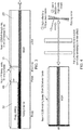
Figure 1a illustrates a distributed feedback laser according to an embodiment; -
Figure 1b illustrates a distributed feedback laser according to a further embodiment; -
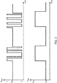
Figure 2 illustrates the driving current and absorption control signal during burst mode operation of a laser according to an embodiment; -
Figure 3 illustrates a tunable laser according to an embodiment; and -
Figure 4 illustrates a laser according to a further embodiment. - Before discussing the embodiments in any more detail, first an overview will be provided.
- In order to reduce temperature fluctuations in lasers that output optical signals intermittently such as in burst mode, a laser that has a substantially constant average electrical power applied to the laser section is provided. This allows the temperature of the laser section which may comprise, a grating, to remain stable, with no self-heating occurring at the beginning of bursts.
- Laser extinction between optical signal output is provided by an optical loss section which may comprise an absorbing section positioned inside the laser cavity, used as an internal switch to turn on the laser during bursts and to turn it off between the bursts.
- If the absorbing section is outside the laser cavity, lasing effect occurs, and extinction is only provided by single propagation along the absorbing section, which struggles to exceed 40dB. Furthermore, this arrangement would require a long absorbing section and higher electrical consumption in the form of a negative Voltage. By providing the absorbing section inside the laser cavity output power can be totally turned off simply by applying a small voltage variation.
- A laser of a first embodiment is illustrated
Figure 1a . Thelaser 5 is composed of twosections section 15 which in this embodiment is formed by H+ implantation. The two sections comprise an active orlaser section 20, and anabsorber section 10. The vertical structure is similar for both structures, with for example multi-quantum wells (MQW). Thelaser section 20 comprises a Bragg grating, which is used to select one single longitudinal mode. - Emitted wavelength is imposed by the laser section : λ = 2.neff.Λ with neff the effective index of laser section, and A the grating pitch.
- In this embodiment, the front facet is antireflection coated (AR), while the back facet is high-reflection coated (HR), such that the oscillating laser cavity is defined between the grating and the back facet. The absorber is positioned between the laser section and the back facet that is inside the lasing or laser cavity.
- In a standard laser without the absorbing section, the laser is turned on and off with the laser or driving current Ilaser set below or under a threshold value. Part of the electrical injected power U.I is transformed into thermal power, leading to laser self-heating ΔT = Rth, U.I where Rth is the thermal resistance (°C/W), U is the voltage, and I the injected current. This temperature increase generates a modification of laser wavelength:

- In the embodiment of
Figure 1a , if current is injected in the laser section, say 80mA, then when the absorption section is under reverse polarization, say Vabs=0V, this section is very absorbing, cavity losses are high, no lasing occurs. When the absorption section is under direct polarization, say Vabs=1V, then this section is transparent or even has a slight gain, thus, cavity losses are low and lasing occurs. - But between these two situations, laser injected electrical power (R.I2) is constant, and as the power variation in the absorbing section is very limited, and distant from the grating section the lasing wavelength remains constant.
- The operation in burst mode is illustrated
figure 2 : - during bursts, the laser is modulated to transmit data, say between I0=20mA and I1=80mA, leading to an electrical power of (Uo. Io+U1.I1)/2. The absorption section is set at Von around 1V to reach transparency, allowing lasing effect.
- between bursts, the laser is set to a continuous current Ioff such that the electrical power is similar to electrical power during bursts: Uoff. Ioff = (Uo. Io+U1.I1)/2. The absorption section is set at Voff around 0V to absorb light and prevent lasing oscillation.
- Embodiments are based on the presence of an optical loss section, in the case of
Figure 1a an absorber, inside the laser cavity. This can be turned to near transparency, transparency or slight amplification during bursts. In the first embodiment, the absorbing section is between the grating laser section and the reflective back facet. In another embodiment illustrated inFigure 1b , the absorbingsection 10 is positioned between twoactive grating sections 20, possibly electrically connected. In this case, the rear facet is anti-reflection coated, and the cavity is defined by the two gratings. - Any other embodiment where an optical loss section such as an absorbing section is inside the cavity, and used to turn on and off the laser can be proposed.
- The embodiments shown in
Figures 1a and 1b have been illustrated with directly modulated lasers. Other embodiments with other modulation schemes, such as externally modulated lasers (EMLs) are also possible. In this case, modulation during bursts is provided by an external modulator, the laser section current is always kept constant, and only absorbing section voltage (or current) is modified during and between bursts to turn off output power. - Alternatively directly modulated lasers can be provided where rather than modulating the lasers using changes in the driving current the output signal is modulated by changing the properties of the optical loss section, that is turning it from high to low loss such that the laser is either outputting a signal or not. Modulating a signal in this way can be done with a low power control signal, providing a greater choice in control signal circuitry. It may be particularly effective where the bit rate and thus, frequency of modulation is relatively low such as with an uplink signal.
-
Figure 3 shows an alternative embodiment showing a tunable laser with the Bragg grating 30 being outside of theactive section 20 and forming a wavelength selective reflector for this cavity. Absorbingsection 10 controls the intermittent operation of the laser, whilephase control section 40 controls the Fabry-Perot mode of resonance of theactive section 20 to align it with the reflective wavelength. Modulation of the signal is provided by modulation of the driving current, however the Burst mode is controlled by the signal applied to the absorbingsection 10. -
Figure 4 shows an alternative way of providing intermittent control where one end of the laser cavity is formed by a controllable mirror. Tilting of the mirror provides the losses required for the optical losses for the cavity return trip to be less than the optical gain and thus, for lasing effects to be suppressed. In this embodiment Fabry-Perot tunable filters are used to select the wavelength of the cavity using the Vernier effect. - A person of skill in the art would readily recognize that steps of various above-described methods can be performed by programmed computers. Herein, some embodiments are also intended to cover program storage devices, e.g., digital data storage media, which are machine or computer readable and encode machine-executable or computer-executable programs of instructions, wherein said instructions perform some or all of the steps of said above-described methods. The program storage devices may be, e.g., digital memories, magnetic storage media such as a magnetic disks and magnetic tapes, hard drives, or optically readable digital data storage media. The embodiments are also intended to cover computers programmed to perform said steps of the above-described methods.
- The functions of the various elements shown in the Figures, including any functional blocks labelled as "processors" or "logic", may be provided through the use of dedicated hardware as well as hardware capable of executing software in association with appropriate software. When provided by a processor, the functions may be provided by a single dedicated processor, by a single shared processor, or by a plurality of individual processors, some of which may be shared. Moreover, explicit use of the term "processor" or "controller" or "logic" should not be construed to refer exclusively to hardware capable of executing software, and may implicitly include, without limitation, digital signal processor (DSP) hardware, network processor, application specific integrated circuit (ASIC), field programmable gate array (FPGA), read only memory (ROM) for storing software, random access memory (RAM), and non-volatile storage. Other hardware, conventional and/or custom, may also be included. Similarly, any switches shown in the Figures are conceptual only. Their function may be carried out through the operation of program logic, through dedicated logic, through the interaction of program control and dedicated logic, or even manually, the particular technique being selectable by the implementer as more specifically understood from the context.
- The description and drawings merely illustrate the principles of the invention. It will thus be appreciated that those skilled in the art will be able to devise various arrangements that, although not explicitly described or shown herein, embody the principles of the invention and are included within its spirit and scope. Furthermore, all examples recited herein are principally intended expressly to be only for pedagogical purposes to aid the reader in understanding the principles of the invention and the concepts contributed by the inventor(s) to furthering the art, and are to be construed as being without limitation to such specifically recited examples and conditions.
- Moreover, all statements herein reciting principles, aspects, and embodiments of the invention, as well as specific examples thereof, are intended to encompass equivalents thereof.
Claims (15)
- A laser, said laser comprising:a resonant laser cavity;said resonant laser cavity comprising at least one active section comprising a material operable to amplify said optical signal in response to a driving current and a controllable optical loss section, said controllable optical loss section being controllable to transition between a high optical loss mode and a lower optical loss mode;a control signal input operable to supply a control signal to said controllable optical loss section to control said section to transition between said high optical loss mode and said lower optical loss mode, a lasing effect of said resonant cavity being suppressed by optical losses when said optical loss section is in said high optical loss mode such that said transitioning of modes of said optical loss section causes said laser to transition between outputting said optical signal and outputting no optical signal.
- A laser according to claim 1, wherein said controllable optical loss section comprises an absorbing section, said absorbing section being configured to absorb optical energy of a wavelength of said optical signal when in said high optical loss mode and to transmit optical energy of said wavelength of said optical signal when in said lower optical loss mode.
- A laser according to claim 2, wherein said absorbing section comprises a semiconductor optical amplifier, said semiconductor optical amplifier being configured to switch between a high optical loss, absorbing mode and a lower optical loss, transparent mode in response to said control signal.
- A laser according to claim 3, wherein said absorbing section is formed of a same material as said material of said active section, said absorbing section being reverse biased when in absorbing mode.
- A laser according to any one of claims 2 to 4, wherein said absorbing section is configured to amplify said optical signal in said lower optical loss mode.
- A laser according to claim 1, wherein said controllable optical loss section comprises one of: a controllable tiltable mirror forming a reflective surface at one end of said resonant laser cavity and a controllable shielding portion for controllably inhibiting transmission of said optical signal within said resonant laser cavity.
- A laser according to any preceding claim, said laser comprising driving current control circuitry for controlling said driving current supplied to said at least one active section such that an average electrical power supplied to said at least one active section is substantially the same during a period when said laser is not emitting said output signal and during a period when said laser is emitting said output signal.
- A laser according to claim 7, wherein said laser comprises an externally modulated laser and said driving current is substantially constant.
- A laser according to claim 7, said laser comprises a directly modulated laser, said driving current control circuitry being configured to modulate said driving current such that said active portion generates a modulated optical signal.
- A laser according to any one of claims 1 to 7, said control circuitry being operable to modulate said output signal by providing a modulation signal to said controllable optical loss section, said modulation signal controlling said section to transition between said lower optical loss mode and said high optical loss mode, said modulated output signal being generated in response to said modulation signal supplied to said controllable optical loss section.
- A laser according to any preceding claim, wherein said at least one active section comprises a Bragg grating.
- A laser according to any one of claims 1 to 10, wherein said resonant cavity further comprises a wavelength selective reflecting portion.
- A laser according to claim 12, wherein said resonant cavity further comprises a phase selecting section.
- A laser according to any preceding claim, said laser comprising control circuitry for controlling said control signal supplied to said optical loss section, said control circuitry being configured to generate a periodically varying control signal to periodically switch said optical loss section from said lower loss mode to said high loss mode such that said laser operates in a burst mode.
- A method of controlling an output of an optical signal from a laser, said method comprising:continuously supplying a driving current to an active section of a resonant cavity of said laser;supplying a changing control signal to an optical loss section of said resonant cavity of said laser, said control signal controlling said optical loss section to periodically transition between a high loss and a lower loss mode, a lasing effect of said resonant cavity being suppressed by increased optical losses when said optical loss section is in said high loss mode; whereinsaid transitioning of modes of said optical loss section causes said laser to transition between outputting said optical signal and outputting no optical signal.
Priority Applications (1)
| Application Number | Priority Date | Filing Date | Title |
|---|---|---|---|
| EP17305301.8A EP3379664B1 (en) | 2017-03-20 | 2017-03-20 | A laser and method of controlling a laser to output a signal intermittently |
Applications Claiming Priority (1)
| Application Number | Priority Date | Filing Date | Title |
|---|---|---|---|
| EP17305301.8A EP3379664B1 (en) | 2017-03-20 | 2017-03-20 | A laser and method of controlling a laser to output a signal intermittently |
Publications (2)
| Publication Number | Publication Date |
|---|---|
| EP3379664A1 true EP3379664A1 (en) | 2018-09-26 |
| EP3379664B1 EP3379664B1 (en) | 2023-06-14 |
Family
ID=58464472
Family Applications (1)
| Application Number | Title | Priority Date | Filing Date |
|---|---|---|---|
| EP17305301.8A Active EP3379664B1 (en) | 2017-03-20 | 2017-03-20 | A laser and method of controlling a laser to output a signal intermittently |
Country Status (1)
| Country | Link |
|---|---|
| EP (1) | EP3379664B1 (en) |
Citations (3)
| Publication number | Priority date | Publication date | Assignee | Title |
|---|---|---|---|---|
| US5572543A (en) * | 1992-04-09 | 1996-11-05 | Deutsch Aerospace Ag | Laser system with a micro-mechanically moved mirror |
| EP1304778A2 (en) * | 2001-10-09 | 2003-04-23 | Xerox Corporation | Laser diode |
| GB2437593A (en) * | 2006-04-25 | 2007-10-31 | Jian-Jun He | A q-modulated semiconductor laser |
-
2017
- 2017-03-20 EP EP17305301.8A patent/EP3379664B1/en active Active
Patent Citations (3)
| Publication number | Priority date | Publication date | Assignee | Title |
|---|---|---|---|---|
| US5572543A (en) * | 1992-04-09 | 1996-11-05 | Deutsch Aerospace Ag | Laser system with a micro-mechanically moved mirror |
| EP1304778A2 (en) * | 2001-10-09 | 2003-04-23 | Xerox Corporation | Laser diode |
| GB2437593A (en) * | 2006-04-25 | 2007-10-31 | Jian-Jun He | A q-modulated semiconductor laser |
Non-Patent Citations (1)
| Title |
|---|
| LEVI A F J ET AL: "MULTIELECTRODE QUANTUM WELL LASER FOR DIGITAL SWITCHING", APPLIED PHYSICS LETTERS, A I P PUBLISHING LLC, US, vol. 56, no. 12, 19 March 1990 (1990-03-19), pages 1095 - 1097, XP000133461, ISSN: 0003-6951, DOI: 10.1063/1.102578 * |
Also Published As
| Publication number | Publication date |
|---|---|
| EP3379664B1 (en) | 2023-06-14 |
Similar Documents
| Publication | Publication Date | Title |
|---|---|---|
| JP3891362B2 (en) | Generation of laser light of different wavelengths | |
| US6650673B2 (en) | Generation of short optical pulses using strongly complex coupled DFB lasers | |
| US5022042A (en) | High power laser array with stable wavelength | |
| US8265112B2 (en) | Semiconductor laser device and circuit for and method of driving same | |
| US6826212B2 (en) | Module for optical communications | |
| Larson et al. | Narrow linewidth high power thermally tuned sampled-grating distributed Bragg reflector laser | |
| US9013785B2 (en) | Tunable multi-mode laser | |
| EP3425755A1 (en) | Surface light emitting laser | |
| JP2006066586A (en) | Mode-locked laser diode and method of controlling wavelength thereof | |
| EP1087478A1 (en) | Generation of short optical pulses using strongly complex coupled DFB lasers. | |
| JP2019083351A (en) | Semiconductor optical amplifier, semiconductor laser module, and wavelength-variable laser assembly | |
| EP2031716A2 (en) | Wavelength control of laser light | |
| US5455836A (en) | Optical Q-switching to generate ultra short pulses in diode lasers | |
| Nunoya et al. | Tunable distributed amplification (TDA-) DFB laser with asymmetric structure | |
| Ujager et al. | A review of semiconductor lasers for optical communications | |
| JP3192293B2 (en) | Optical transmission equipment | |
| US4639922A (en) | Single mode injection laser structure | |
| Hisham et al. | Characterization of transient response in fiber grating fabry–perot lasers | |
| EP3379664B1 (en) | A laser and method of controlling a laser to output a signal intermittently | |
| Ishii et al. | High-power (40mW) L-band tunable DFB laser array module using current tuning | |
| JP2009521120A (en) | Laser tuning | |
| US6795472B2 (en) | Laser with a resonant optical reflector | |
| Zhu et al. | Multiwavelength picosecond optical pulse generation using an actively mode-locked multichannel grating cavity laser | |
| Su et al. | Compact Tunable Laser Array for WDM-PON in 5G wireless networks | |
| WO2025161830A1 (en) | Laser, laser array and optical device |
Legal Events
| Date | Code | Title | Description |
|---|---|---|---|
| PUAI | Public reference made under article 153(3) epc to a published international application that has entered the european phase |
Free format text: ORIGINAL CODE: 0009012 |
|
| STAA | Information on the status of an ep patent application or granted ep patent |
Free format text: STATUS: THE APPLICATION HAS BEEN PUBLISHED |
|
| AK | Designated contracting states |
Kind code of ref document: A1 Designated state(s): AL AT BE BG CH CY CZ DE DK EE ES FI FR GB GR HR HU IE IS IT LI LT LU LV MC MK MT NL NO PL PT RO RS SE SI SK SM TR |
|
| AX | Request for extension of the european patent |
Extension state: BA ME |
|
| STAA | Information on the status of an ep patent application or granted ep patent |
Free format text: STATUS: REQUEST FOR EXAMINATION WAS MADE |
|
| 17P | Request for examination filed |
Effective date: 20190326 |
|
| RBV | Designated contracting states (corrected) |
Designated state(s): AL AT BE BG CH CY CZ DE DK EE ES FI FR GB GR HR HU IE IS IT LI LT LU LV MC MK MT NL NO PL PT RO RS SE SI SK SM TR |
|
| RAP1 | Party data changed (applicant data changed or rights of an application transferred) |
Owner name: NOKIA SOLUTIONS AND NETWORKS OY |
|
| STAA | Information on the status of an ep patent application or granted ep patent |
Free format text: STATUS: EXAMINATION IS IN PROGRESS |
|
| 17Q | First examination report despatched |
Effective date: 20200409 |
|
| RIC1 | Information provided on ipc code assigned before grant |
Ipc: H01S 5/028 20060101ALN20220217BHEP Ipc: H01S 3/105 20060101ALN20220217BHEP Ipc: H01S 3/10 20060101ALN20220217BHEP Ipc: H01S 5/14 20060101ALI20220217BHEP Ipc: H01S 5/0625 20060101AFI20220217BHEP |
|
| GRAP | Despatch of communication of intention to grant a patent |
Free format text: ORIGINAL CODE: EPIDOSNIGR1 |
|
| STAA | Information on the status of an ep patent application or granted ep patent |
Free format text: STATUS: GRANT OF PATENT IS INTENDED |
|
| INTG | Intention to grant announced |
Effective date: 20220510 |
|
| GRAJ | Information related to disapproval of communication of intention to grant by the applicant or resumption of examination proceedings by the epo deleted |
Free format text: ORIGINAL CODE: EPIDOSDIGR1 |
|
| STAA | Information on the status of an ep patent application or granted ep patent |
Free format text: STATUS: EXAMINATION IS IN PROGRESS |
|
| INTC | Intention to grant announced (deleted) | ||
| RIC1 | Information provided on ipc code assigned before grant |
Ipc: H01S 5/028 20060101ALN20220915BHEP Ipc: H01S 3/105 20060101ALN20220915BHEP Ipc: H01S 3/10 20060101ALN20220915BHEP Ipc: H01S 5/14 20060101ALI20220915BHEP Ipc: H01S 5/0625 20060101AFI20220915BHEP |
|
| RIC1 | Information provided on ipc code assigned before grant |
Ipc: H01S 5/028 20060101ALN20220928BHEP Ipc: H01S 3/105 20060101ALN20220928BHEP Ipc: H01S 3/10 20060101ALN20220928BHEP Ipc: H01S 5/14 20060101ALI20220928BHEP Ipc: H01S 5/0625 20060101AFI20220928BHEP |
|
| GRAP | Despatch of communication of intention to grant a patent |
Free format text: ORIGINAL CODE: EPIDOSNIGR1 |
|
| STAA | Information on the status of an ep patent application or granted ep patent |
Free format text: STATUS: GRANT OF PATENT IS INTENDED |
|
| INTG | Intention to grant announced |
Effective date: 20221124 |
|
| GRAJ | Information related to disapproval of communication of intention to grant by the applicant or resumption of examination proceedings by the epo deleted |
Free format text: ORIGINAL CODE: EPIDOSDIGR1 |
|
| STAA | Information on the status of an ep patent application or granted ep patent |
Free format text: STATUS: EXAMINATION IS IN PROGRESS |
|
| GRAP | Despatch of communication of intention to grant a patent |
Free format text: ORIGINAL CODE: EPIDOSNIGR1 |
|
| STAA | Information on the status of an ep patent application or granted ep patent |
Free format text: STATUS: GRANT OF PATENT IS INTENDED |
|
| INTC | Intention to grant announced (deleted) | ||
| RIC1 | Information provided on ipc code assigned before grant |
Ipc: H01S 5/028 20060101ALN20230327BHEP Ipc: H01S 3/105 20060101ALN20230327BHEP Ipc: H01S 3/10 20060101ALN20230327BHEP Ipc: H01S 5/14 20060101ALI20230327BHEP Ipc: H01S 5/0625 20060101AFI20230327BHEP |
|
| GRAS | Grant fee paid |
Free format text: ORIGINAL CODE: EPIDOSNIGR3 |
|
| GRAA | (expected) grant |
Free format text: ORIGINAL CODE: 0009210 |
|
| STAA | Information on the status of an ep patent application or granted ep patent |
Free format text: STATUS: THE PATENT HAS BEEN GRANTED |
|
| INTG | Intention to grant announced |
Effective date: 20230421 |
|
| AK | Designated contracting states |
Kind code of ref document: B1 Designated state(s): AL AT BE BG CH CY CZ DE DK EE ES FI FR GB GR HR HU IE IS IT LI LT LU LV MC MK MT NL NO PL PT RO RS SE SI SK SM TR |
|
| REG | Reference to a national code |
Ref country code: CH Ref legal event code: EP |
|
| REG | Reference to a national code |
Ref country code: DE Ref legal event code: R096 Ref document number: 602017070163 Country of ref document: DE |
|
| REG | Reference to a national code |
Ref country code: AT Ref legal event code: REF Ref document number: 1579939 Country of ref document: AT Kind code of ref document: T Effective date: 20230715 |
|
| REG | Reference to a national code |
Ref country code: LT Ref legal event code: MG9D |
|
| REG | Reference to a national code |
Ref country code: NL Ref legal event code: MP Effective date: 20230614 |
|
| PG25 | Lapsed in a contracting state [announced via postgrant information from national office to epo] |
Ref country code: SE Free format text: LAPSE BECAUSE OF FAILURE TO SUBMIT A TRANSLATION OF THE DESCRIPTION OR TO PAY THE FEE WITHIN THE PRESCRIBED TIME-LIMIT Effective date: 20230614 Ref country code: NO Free format text: LAPSE BECAUSE OF FAILURE TO SUBMIT A TRANSLATION OF THE DESCRIPTION OR TO PAY THE FEE WITHIN THE PRESCRIBED TIME-LIMIT Effective date: 20230914 Ref country code: ES Free format text: LAPSE BECAUSE OF FAILURE TO SUBMIT A TRANSLATION OF THE DESCRIPTION OR TO PAY THE FEE WITHIN THE PRESCRIBED TIME-LIMIT Effective date: 20230614 |
|
| REG | Reference to a national code |
Ref country code: AT Ref legal event code: MK05 Ref document number: 1579939 Country of ref document: AT Kind code of ref document: T Effective date: 20230614 |
|
| PG25 | Lapsed in a contracting state [announced via postgrant information from national office to epo] |
Ref country code: RS Free format text: LAPSE BECAUSE OF FAILURE TO SUBMIT A TRANSLATION OF THE DESCRIPTION OR TO PAY THE FEE WITHIN THE PRESCRIBED TIME-LIMIT Effective date: 20230614 Ref country code: NL Free format text: LAPSE BECAUSE OF FAILURE TO SUBMIT A TRANSLATION OF THE DESCRIPTION OR TO PAY THE FEE WITHIN THE PRESCRIBED TIME-LIMIT Effective date: 20230614 Ref country code: LV Free format text: LAPSE BECAUSE OF FAILURE TO SUBMIT A TRANSLATION OF THE DESCRIPTION OR TO PAY THE FEE WITHIN THE PRESCRIBED TIME-LIMIT Effective date: 20230614 Ref country code: LT Free format text: LAPSE BECAUSE OF FAILURE TO SUBMIT A TRANSLATION OF THE DESCRIPTION OR TO PAY THE FEE WITHIN THE PRESCRIBED TIME-LIMIT Effective date: 20230614 Ref country code: HR Free format text: LAPSE BECAUSE OF FAILURE TO SUBMIT A TRANSLATION OF THE DESCRIPTION OR TO PAY THE FEE WITHIN THE PRESCRIBED TIME-LIMIT Effective date: 20230614 Ref country code: GR Free format text: LAPSE BECAUSE OF FAILURE TO SUBMIT A TRANSLATION OF THE DESCRIPTION OR TO PAY THE FEE WITHIN THE PRESCRIBED TIME-LIMIT Effective date: 20230915 |
|
| PG25 | Lapsed in a contracting state [announced via postgrant information from national office to epo] |
Ref country code: FI Free format text: LAPSE BECAUSE OF FAILURE TO SUBMIT A TRANSLATION OF THE DESCRIPTION OR TO PAY THE FEE WITHIN THE PRESCRIBED TIME-LIMIT Effective date: 20230614 |
|
| PG25 | Lapsed in a contracting state [announced via postgrant information from national office to epo] |
Ref country code: SK Free format text: LAPSE BECAUSE OF FAILURE TO SUBMIT A TRANSLATION OF THE DESCRIPTION OR TO PAY THE FEE WITHIN THE PRESCRIBED TIME-LIMIT Effective date: 20230614 |
|
| PG25 | Lapsed in a contracting state [announced via postgrant information from national office to epo] |
Ref country code: IS Free format text: LAPSE BECAUSE OF FAILURE TO SUBMIT A TRANSLATION OF THE DESCRIPTION OR TO PAY THE FEE WITHIN THE PRESCRIBED TIME-LIMIT Effective date: 20231014 |
|
| PG25 | Lapsed in a contracting state [announced via postgrant information from national office to epo] |
Ref country code: SM Free format text: LAPSE BECAUSE OF FAILURE TO SUBMIT A TRANSLATION OF THE DESCRIPTION OR TO PAY THE FEE WITHIN THE PRESCRIBED TIME-LIMIT Effective date: 20230614 Ref country code: SK Free format text: LAPSE BECAUSE OF FAILURE TO SUBMIT A TRANSLATION OF THE DESCRIPTION OR TO PAY THE FEE WITHIN THE PRESCRIBED TIME-LIMIT Effective date: 20230614 Ref country code: RO Free format text: LAPSE BECAUSE OF FAILURE TO SUBMIT A TRANSLATION OF THE DESCRIPTION OR TO PAY THE FEE WITHIN THE PRESCRIBED TIME-LIMIT Effective date: 20230614 Ref country code: PT Free format text: LAPSE BECAUSE OF FAILURE TO SUBMIT A TRANSLATION OF THE DESCRIPTION OR TO PAY THE FEE WITHIN THE PRESCRIBED TIME-LIMIT Effective date: 20231016 Ref country code: IS Free format text: LAPSE BECAUSE OF FAILURE TO SUBMIT A TRANSLATION OF THE DESCRIPTION OR TO PAY THE FEE WITHIN THE PRESCRIBED TIME-LIMIT Effective date: 20231014 Ref country code: EE Free format text: LAPSE BECAUSE OF FAILURE TO SUBMIT A TRANSLATION OF THE DESCRIPTION OR TO PAY THE FEE WITHIN THE PRESCRIBED TIME-LIMIT Effective date: 20230614 Ref country code: CZ Free format text: LAPSE BECAUSE OF FAILURE TO SUBMIT A TRANSLATION OF THE DESCRIPTION OR TO PAY THE FEE WITHIN THE PRESCRIBED TIME-LIMIT Effective date: 20230614 Ref country code: AT Free format text: LAPSE BECAUSE OF FAILURE TO SUBMIT A TRANSLATION OF THE DESCRIPTION OR TO PAY THE FEE WITHIN THE PRESCRIBED TIME-LIMIT Effective date: 20230614 |
|
| PG25 | Lapsed in a contracting state [announced via postgrant information from national office to epo] |
Ref country code: PL Free format text: LAPSE BECAUSE OF FAILURE TO SUBMIT A TRANSLATION OF THE DESCRIPTION OR TO PAY THE FEE WITHIN THE PRESCRIBED TIME-LIMIT Effective date: 20230614 |
|
| REG | Reference to a national code |
Ref country code: DE Ref legal event code: R097 Ref document number: 602017070163 Country of ref document: DE |
|
| PLBE | No opposition filed within time limit |
Free format text: ORIGINAL CODE: 0009261 |
|
| STAA | Information on the status of an ep patent application or granted ep patent |
Free format text: STATUS: NO OPPOSITION FILED WITHIN TIME LIMIT |
|
| PG25 | Lapsed in a contracting state [announced via postgrant information from national office to epo] |
Ref country code: DK Free format text: LAPSE BECAUSE OF FAILURE TO SUBMIT A TRANSLATION OF THE DESCRIPTION OR TO PAY THE FEE WITHIN THE PRESCRIBED TIME-LIMIT Effective date: 20230614 |
|
| PG25 | Lapsed in a contracting state [announced via postgrant information from national office to epo] |
Ref country code: SI Free format text: LAPSE BECAUSE OF FAILURE TO SUBMIT A TRANSLATION OF THE DESCRIPTION OR TO PAY THE FEE WITHIN THE PRESCRIBED TIME-LIMIT Effective date: 20230614 |
|
| 26N | No opposition filed |
Effective date: 20240315 |
|
| PG25 | Lapsed in a contracting state [announced via postgrant information from national office to epo] |
Ref country code: SI Free format text: LAPSE BECAUSE OF FAILURE TO SUBMIT A TRANSLATION OF THE DESCRIPTION OR TO PAY THE FEE WITHIN THE PRESCRIBED TIME-LIMIT Effective date: 20230614 Ref country code: IT Free format text: LAPSE BECAUSE OF FAILURE TO SUBMIT A TRANSLATION OF THE DESCRIPTION OR TO PAY THE FEE WITHIN THE PRESCRIBED TIME-LIMIT Effective date: 20230614 |
|
| REG | Reference to a national code |
Ref country code: CH Ref legal event code: PL |
|
| PG25 | Lapsed in a contracting state [announced via postgrant information from national office to epo] |
Ref country code: BG Free format text: LAPSE BECAUSE OF FAILURE TO SUBMIT A TRANSLATION OF THE DESCRIPTION OR TO PAY THE FEE WITHIN THE PRESCRIBED TIME-LIMIT Effective date: 20230614 |
|
| PG25 | Lapsed in a contracting state [announced via postgrant information from national office to epo] |
Ref country code: LU Free format text: LAPSE BECAUSE OF NON-PAYMENT OF DUE FEES Effective date: 20240320 |
|
| PG25 | Lapsed in a contracting state [announced via postgrant information from national office to epo] |
Ref country code: MC Free format text: LAPSE BECAUSE OF FAILURE TO SUBMIT A TRANSLATION OF THE DESCRIPTION OR TO PAY THE FEE WITHIN THE PRESCRIBED TIME-LIMIT Effective date: 20230614 |
|
| PG25 | Lapsed in a contracting state [announced via postgrant information from national office to epo] |
Ref country code: MC Free format text: LAPSE BECAUSE OF FAILURE TO SUBMIT A TRANSLATION OF THE DESCRIPTION OR TO PAY THE FEE WITHIN THE PRESCRIBED TIME-LIMIT Effective date: 20230614 Ref country code: LU Free format text: LAPSE BECAUSE OF NON-PAYMENT OF DUE FEES Effective date: 20240320 Ref country code: BG Free format text: LAPSE BECAUSE OF FAILURE TO SUBMIT A TRANSLATION OF THE DESCRIPTION OR TO PAY THE FEE WITHIN THE PRESCRIBED TIME-LIMIT Effective date: 20230614 |
|
| REG | Reference to a national code |
Ref country code: BE Ref legal event code: MM Effective date: 20240331 |
|
| PG25 | Lapsed in a contracting state [announced via postgrant information from national office to epo] |
Ref country code: BE Free format text: LAPSE BECAUSE OF NON-PAYMENT OF DUE FEES Effective date: 20240331 |
|
| PG25 | Lapsed in a contracting state [announced via postgrant information from national office to epo] |
Ref country code: FR Free format text: LAPSE BECAUSE OF NON-PAYMENT OF DUE FEES Effective date: 20240331 |
|
| PG25 | Lapsed in a contracting state [announced via postgrant information from national office to epo] |
Ref country code: IE Free format text: LAPSE BECAUSE OF NON-PAYMENT OF DUE FEES Effective date: 20240320 |
|
| PG25 | Lapsed in a contracting state [announced via postgrant information from national office to epo] |
Ref country code: IE Free format text: LAPSE BECAUSE OF NON-PAYMENT OF DUE FEES Effective date: 20240320 Ref country code: FR Free format text: LAPSE BECAUSE OF NON-PAYMENT OF DUE FEES Effective date: 20240331 Ref country code: BE Free format text: LAPSE BECAUSE OF NON-PAYMENT OF DUE FEES Effective date: 20240331 Ref country code: CH Free format text: LAPSE BECAUSE OF NON-PAYMENT OF DUE FEES Effective date: 20240331 |
|
| PG25 | Lapsed in a contracting state [announced via postgrant information from national office to epo] |
Ref country code: CY Free format text: LAPSE BECAUSE OF FAILURE TO SUBMIT A TRANSLATION OF THE DESCRIPTION OR TO PAY THE FEE WITHIN THE PRESCRIBED TIME-LIMIT; INVALID AB INITIO Effective date: 20170320 |
|
| PG25 | Lapsed in a contracting state [announced via postgrant information from national office to epo] |
Ref country code: HU Free format text: LAPSE BECAUSE OF FAILURE TO SUBMIT A TRANSLATION OF THE DESCRIPTION OR TO PAY THE FEE WITHIN THE PRESCRIBED TIME-LIMIT; INVALID AB INITIO Effective date: 20170320 |
|
| PG25 | Lapsed in a contracting state [announced via postgrant information from national office to epo] |
Ref country code: TR Free format text: LAPSE BECAUSE OF FAILURE TO SUBMIT A TRANSLATION OF THE DESCRIPTION OR TO PAY THE FEE WITHIN THE PRESCRIBED TIME-LIMIT Effective date: 20230614 |
|
| PGFP | Annual fee paid to national office [announced via postgrant information from national office to epo] |
Ref country code: GB Payment date: 20260202 Year of fee payment: 10 |
|
| PGFP | Annual fee paid to national office [announced via postgrant information from national office to epo] |
Ref country code: DE Payment date: 20260204 Year of fee payment: 10 |