EP3379617A1 - Lithium secondary battery - Google Patents
Lithium secondary battery Download PDFInfo
- Publication number
- EP3379617A1 EP3379617A1 EP18163167.2A EP18163167A EP3379617A1 EP 3379617 A1 EP3379617 A1 EP 3379617A1 EP 18163167 A EP18163167 A EP 18163167A EP 3379617 A1 EP3379617 A1 EP 3379617A1
- Authority
- EP
- European Patent Office
- Prior art keywords
- lithium secondary
- secondary battery
- passivation layer
- discharging
- charging
- Prior art date
- Legal status (The legal status is an assumption and is not a legal conclusion. Google has not performed a legal analysis and makes no representation as to the accuracy of the status listed.)
- Granted
Links
Images






Classifications
-
- H—ELECTRICITY
- H01—ELECTRIC ELEMENTS
- H01M—PROCESSES OR MEANS, e.g. BATTERIES, FOR THE DIRECT CONVERSION OF CHEMICAL ENERGY INTO ELECTRICAL ENERGY
- H01M4/00—Electrodes
- H01M4/02—Electrodes composed of, or comprising, active material
- H01M4/13—Electrodes for accumulators with non-aqueous electrolyte, e.g. for lithium-accumulators; Processes of manufacture thereof
- H01M4/133—Electrodes based on carbonaceous material, e.g. graphite-intercalation compounds or CFx
-
- H—ELECTRICITY
- H01—ELECTRIC ELEMENTS
- H01M—PROCESSES OR MEANS, e.g. BATTERIES, FOR THE DIRECT CONVERSION OF CHEMICAL ENERGY INTO ELECTRICAL ENERGY
- H01M4/00—Electrodes
- H01M4/02—Electrodes composed of, or comprising, active material
- H01M4/04—Processes of manufacture in general
- H01M4/0438—Processes of manufacture in general by electrochemical processing
- H01M4/044—Activating, forming or electrochemical attack of the supporting material
- H01M4/0445—Forming after manufacture of the electrode, e.g. first charge, cycling
- H01M4/0447—Forming after manufacture of the electrode, e.g. first charge, cycling of complete cells or cells stacks
-
- H—ELECTRICITY
- H01—ELECTRIC ELEMENTS
- H01M—PROCESSES OR MEANS, e.g. BATTERIES, FOR THE DIRECT CONVERSION OF CHEMICAL ENERGY INTO ELECTRICAL ENERGY
- H01M4/00—Electrodes
- H01M4/02—Electrodes composed of, or comprising, active material
- H01M4/04—Processes of manufacture in general
- H01M4/0438—Processes of manufacture in general by electrochemical processing
- H01M4/044—Activating, forming or electrochemical attack of the supporting material
- H01M4/0445—Forming after manufacture of the electrode, e.g. first charge, cycling
-
- H—ELECTRICITY
- H01—ELECTRIC ELEMENTS
- H01M—PROCESSES OR MEANS, e.g. BATTERIES, FOR THE DIRECT CONVERSION OF CHEMICAL ENERGY INTO ELECTRICAL ENERGY
- H01M4/00—Electrodes
- H01M4/02—Electrodes composed of, or comprising, active material
- H01M4/62—Selection of inactive substances as ingredients for active masses, e.g. binders, fillers
- H01M4/628—Inhibitors, e.g. gassing inhibitors, corrosion inhibitors
-
- H—ELECTRICITY
- H01—ELECTRIC ELEMENTS
- H01M—PROCESSES OR MEANS, e.g. BATTERIES, FOR THE DIRECT CONVERSION OF CHEMICAL ENERGY INTO ELECTRICAL ENERGY
- H01M10/00—Secondary cells; Manufacture thereof
- H01M10/04—Construction or manufacture in general
- H01M10/049—Processes for forming or storing electrodes in the battery container
-
- H—ELECTRICITY
- H01—ELECTRIC ELEMENTS
- H01M—PROCESSES OR MEANS, e.g. BATTERIES, FOR THE DIRECT CONVERSION OF CHEMICAL ENERGY INTO ELECTRICAL ENERGY
- H01M10/00—Secondary cells; Manufacture thereof
- H01M10/05—Accumulators with non-aqueous electrolyte
- H01M10/052—Li-accumulators
-
- H—ELECTRICITY
- H01—ELECTRIC ELEMENTS
- H01M—PROCESSES OR MEANS, e.g. BATTERIES, FOR THE DIRECT CONVERSION OF CHEMICAL ENERGY INTO ELECTRICAL ENERGY
- H01M10/00—Secondary cells; Manufacture thereof
- H01M10/05—Accumulators with non-aqueous electrolyte
- H01M10/052—Li-accumulators
- H01M10/0525—Rocking-chair batteries, i.e. batteries with lithium insertion or intercalation in both electrodes; Lithium-ion batteries
-
- H—ELECTRICITY
- H01—ELECTRIC ELEMENTS
- H01M—PROCESSES OR MEANS, e.g. BATTERIES, FOR THE DIRECT CONVERSION OF CHEMICAL ENERGY INTO ELECTRICAL ENERGY
- H01M10/00—Secondary cells; Manufacture thereof
- H01M10/05—Accumulators with non-aqueous electrolyte
- H01M10/056—Accumulators with non-aqueous electrolyte characterised by the materials used as electrolytes, e.g. mixed inorganic/organic electrolytes
- H01M10/0564—Accumulators with non-aqueous electrolyte characterised by the materials used as electrolytes, e.g. mixed inorganic/organic electrolytes the electrolyte being constituted of organic materials only
- H01M10/0566—Liquid materials
- H01M10/0567—Liquid materials characterised by the additives
-
- H—ELECTRICITY
- H01—ELECTRIC ELEMENTS
- H01M—PROCESSES OR MEANS, e.g. BATTERIES, FOR THE DIRECT CONVERSION OF CHEMICAL ENERGY INTO ELECTRICAL ENERGY
- H01M10/00—Secondary cells; Manufacture thereof
- H01M10/05—Accumulators with non-aqueous electrolyte
- H01M10/058—Construction or manufacture
-
- H—ELECTRICITY
- H01—ELECTRIC ELEMENTS
- H01M—PROCESSES OR MEANS, e.g. BATTERIES, FOR THE DIRECT CONVERSION OF CHEMICAL ENERGY INTO ELECTRICAL ENERGY
- H01M10/00—Secondary cells; Manufacture thereof
- H01M10/05—Accumulators with non-aqueous electrolyte
- H01M10/058—Construction or manufacture
- H01M10/0587—Construction or manufacture of accumulators having only wound construction elements, i.e. wound positive electrodes, wound negative electrodes and wound separators
-
- H—ELECTRICITY
- H01—ELECTRIC ELEMENTS
- H01M—PROCESSES OR MEANS, e.g. BATTERIES, FOR THE DIRECT CONVERSION OF CHEMICAL ENERGY INTO ELECTRICAL ENERGY
- H01M10/00—Secondary cells; Manufacture thereof
- H01M10/42—Methods or arrangements for servicing or maintenance of secondary cells or secondary half-cells
- H01M10/44—Methods for charging or discharging
-
- H—ELECTRICITY
- H01—ELECTRIC ELEMENTS
- H01M—PROCESSES OR MEANS, e.g. BATTERIES, FOR THE DIRECT CONVERSION OF CHEMICAL ENERGY INTO ELECTRICAL ENERGY
- H01M10/00—Secondary cells; Manufacture thereof
- H01M10/42—Methods or arrangements for servicing or maintenance of secondary cells or secondary half-cells
- H01M10/44—Methods for charging or discharging
- H01M10/446—Initial charging measures
-
- H—ELECTRICITY
- H01—ELECTRIC ELEMENTS
- H01M—PROCESSES OR MEANS, e.g. BATTERIES, FOR THE DIRECT CONVERSION OF CHEMICAL ENERGY INTO ELECTRICAL ENERGY
- H01M4/00—Electrodes
- H01M4/02—Electrodes composed of, or comprising, active material
- H01M4/13—Electrodes for accumulators with non-aqueous electrolyte, e.g. for lithium-accumulators; Processes of manufacture thereof
-
- H—ELECTRICITY
- H01—ELECTRIC ELEMENTS
- H01M—PROCESSES OR MEANS, e.g. BATTERIES, FOR THE DIRECT CONVERSION OF CHEMICAL ENERGY INTO ELECTRICAL ENERGY
- H01M4/00—Electrodes
- H01M4/02—Electrodes composed of, or comprising, active material
- H01M4/13—Electrodes for accumulators with non-aqueous electrolyte, e.g. for lithium-accumulators; Processes of manufacture thereof
- H01M4/139—Processes of manufacture
-
- H—ELECTRICITY
- H01—ELECTRIC ELEMENTS
- H01M—PROCESSES OR MEANS, e.g. BATTERIES, FOR THE DIRECT CONVERSION OF CHEMICAL ENERGY INTO ELECTRICAL ENERGY
- H01M4/00—Electrodes
- H01M4/02—Electrodes composed of, or comprising, active material
- H01M4/36—Selection of substances as active materials, active masses, active liquids
- H01M4/362—Composites
- H01M4/366—Composites as layered products
-
- H—ELECTRICITY
- H01—ELECTRIC ELEMENTS
- H01M—PROCESSES OR MEANS, e.g. BATTERIES, FOR THE DIRECT CONVERSION OF CHEMICAL ENERGY INTO ELECTRICAL ENERGY
- H01M4/00—Electrodes
- H01M4/02—Electrodes composed of, or comprising, active material
- H01M4/36—Selection of substances as active materials, active masses, active liquids
- H01M4/58—Selection of substances as active materials, active masses, active liquids of inorganic compounds other than oxides or hydroxides, e.g. sulfides, selenides, tellurides, halogenides or LiCoFy; of polyanionic structures, e.g. phosphates, silicates or borates
- H01M4/583—Carbonaceous material, e.g. graphite-intercalation compounds or CFx
- H01M4/587—Carbonaceous material, e.g. graphite-intercalation compounds or CFx for inserting or intercalating light metals
-
- H—ELECTRICITY
- H01—ELECTRIC ELEMENTS
- H01M—PROCESSES OR MEANS, e.g. BATTERIES, FOR THE DIRECT CONVERSION OF CHEMICAL ENERGY INTO ELECTRICAL ENERGY
- H01M4/00—Electrodes
- H01M4/02—Electrodes composed of, or comprising, active material
- H01M2004/026—Electrodes composed of, or comprising, active material characterised by the polarity
- H01M2004/027—Negative electrodes
-
- H—ELECTRICITY
- H01—ELECTRIC ELEMENTS
- H01M—PROCESSES OR MEANS, e.g. BATTERIES, FOR THE DIRECT CONVERSION OF CHEMICAL ENERGY INTO ELECTRICAL ENERGY
- H01M2300/00—Electrolytes
- H01M2300/0017—Non-aqueous electrolytes
- H01M2300/0025—Organic electrolyte
-
- H—ELECTRICITY
- H01—ELECTRIC ELEMENTS
- H01M—PROCESSES OR MEANS, e.g. BATTERIES, FOR THE DIRECT CONVERSION OF CHEMICAL ENERGY INTO ELECTRICAL ENERGY
- H01M4/00—Electrodes
- H01M4/02—Electrodes composed of, or comprising, active material
- H01M4/13—Electrodes for accumulators with non-aqueous electrolyte, e.g. for lithium-accumulators; Processes of manufacture thereof
- H01M4/139—Processes of manufacture
- H01M4/1393—Processes of manufacture of electrodes based on carbonaceous material, e.g. graphite-intercalation compounds or CFx
-
- Y—GENERAL TAGGING OF NEW TECHNOLOGICAL DEVELOPMENTS; GENERAL TAGGING OF CROSS-SECTIONAL TECHNOLOGIES SPANNING OVER SEVERAL SECTIONS OF THE IPC; TECHNICAL SUBJECTS COVERED BY FORMER USPC CROSS-REFERENCE ART COLLECTIONS [XRACs] AND DIGESTS
- Y02—TECHNOLOGIES OR APPLICATIONS FOR MITIGATION OR ADAPTATION AGAINST CLIMATE CHANGE
- Y02E—REDUCTION OF GREENHOUSE GAS [GHG] EMISSIONS, RELATED TO ENERGY GENERATION, TRANSMISSION OR DISTRIBUTION
- Y02E60/00—Enabling technologies; Technologies with a potential or indirect contribution to GHG emissions mitigation
- Y02E60/10—Energy storage using batteries
-
- Y—GENERAL TAGGING OF NEW TECHNOLOGICAL DEVELOPMENTS; GENERAL TAGGING OF CROSS-SECTIONAL TECHNOLOGIES SPANNING OVER SEVERAL SECTIONS OF THE IPC; TECHNICAL SUBJECTS COVERED BY FORMER USPC CROSS-REFERENCE ART COLLECTIONS [XRACs] AND DIGESTS
- Y02—TECHNOLOGIES OR APPLICATIONS FOR MITIGATION OR ADAPTATION AGAINST CLIMATE CHANGE
- Y02P—CLIMATE CHANGE MITIGATION TECHNOLOGIES IN THE PRODUCTION OR PROCESSING OF GOODS
- Y02P70/00—Climate change mitigation technologies in the production process for final industrial or consumer products
- Y02P70/50—Manufacturing or production processes characterised by the final manufactured product
-
- Y—GENERAL TAGGING OF NEW TECHNOLOGICAL DEVELOPMENTS; GENERAL TAGGING OF CROSS-SECTIONAL TECHNOLOGIES SPANNING OVER SEVERAL SECTIONS OF THE IPC; TECHNICAL SUBJECTS COVERED BY FORMER USPC CROSS-REFERENCE ART COLLECTIONS [XRACs] AND DIGESTS
- Y02—TECHNOLOGIES OR APPLICATIONS FOR MITIGATION OR ADAPTATION AGAINST CLIMATE CHANGE
- Y02T—CLIMATE CHANGE MITIGATION TECHNOLOGIES RELATED TO TRANSPORTATION
- Y02T10/00—Road transport of goods or passengers
- Y02T10/60—Other road transportation technologies with climate change mitigation effect
- Y02T10/70—Energy storage systems for electromobility, e.g. batteries
Definitions
- One or more embodiments relate to lithium secondary batteries including a passivation layer formed on a surface of a negative electrode.
- a lithium secondary battery generally includes a positive electrode, a negative electrode, and an electrolyte.
- the electrolyte When the electrolyte is brought into contact with active materials of the electrodes, oxidation and reduction reactions of components of the electrolyte occur. Although some products of these reactions are desorbed or eluted therefrom, others are deposited on the surface of the electrode to form a passivation layer on the surface of an active material.
- the passivation layer Since the behavior of the passivation layer is similar to that of a solid electrolyte, due to a very low electronic conductivity and a very high lithium ion conductivity, the passivation layer is also referred to as a solid electrolyte interphase (SEI) layer.
- SEI solid electrolyte interphase
- One or more embodiments include a lithium secondary battery having a high initial efficiency and a high capacity during charging and discharging.
- One or more embodiments include a lithium secondary battery having a high capacity and a long lifespan by suppressing a thickness increase of the battery during charging and discharging.
- a lithium secondary battery as set out in claim 1.
- Preferred features of this aspect are set out in claims 2 to 12.
- Preferred features of this aspect are set out in claims 14 and 15.
- a lithium secondary battery includes a positive electrode, a negative electrode, and an electrolyte interposed between the positive electrode and the negative electrode, wherein a passivation layer is formed on at least one portion of a surface of the negative electrode after one or more cycles of charging and discharging of the lithium secondary battery and the passivation layer includes a particulate passivation layer and a film-like passivation layer.
- the lithium secondary battery according to the embodiment may have excellent lifespan characteristics and high capacity by suppressing thickness changes in cells.
- a thickness of the film-like passivation layer may be 10 nm or greater.
- the thickness of the film-like passivation layer may be 15 nm or greater, for example, 20 nm or greater, without embodiments being limited thereto.
- the thickness of the film-like passivation layer may be from about 10 nm to about 300 nm, for example from about 15 nm to about 150 nm, or from about 20 nm to about 80 nm, without embodiments being limited thereto.
- a thickness D 1 of the film-like passivation layer may be 10 nm or greater, for example, 15 nm or greater, or 20 nm or greater after one cycle of charging and discharging of the lithium secondary battery, without embodiments being limited thereto.
- the thickness D 1 of the film-like passivation layer may be from about 10 nm to about 300 nm, for example from about 15 nm to about 150 nm, or from about 20 nm to about 80 nm after one cycle of charging and discharging of the lithium secondary battery, without embodiments being limited thereto.
- a ratio D 300 /D 1 of a thickness D 300 of the film-like passivation layer after 300 cycles of charging and discharging of the lithium secondary battery to a thickness D 1 of the film-like passivation layer after one cycle of charging and discharging of the lithium secondary battery is from about 1.0 to 1.5, for example from about 1.0 to about 1.15, or from about 1.01 to about 1.1. That is, the lithium secondary battery may have long lifespan and high capacity due to small thickness changes in the passivation layer.
- the thickness of the particulate passivation layer may be from about 100 to about 600 nm, for example from about 100 to about 400 nm.
- the particulate passivation layer has a three-dimensional structure or a shape in which a plurality of spherical particles aggregate.
- the particulate passivation layer may include spherical particles having an average diameter of about 50 nm to about 500 nm, for example, about 100 nm to about 200 nm.
- the lithium secondary battery may have excellent lifespan and capacity characteristics since a resistance increase in the battery is inhibited in comparison with a lithium secondary battery including a particulate passivation layer densely formed of smaller particles with a smaller average diameter and the lithium secondary battery may also have a less thickness increase in initial cells in comparison with a lithium secondary battery including a particulate passivation layer formed of larger particles with a larger average diameter.
- the average diameter may be determined by measuring the diameters of spherical particles on scanning electronic microscope (SEM) images.
- a ratio of the thickness of the particulate passivation layer to the thickness of the film-like passivation layer may be from about 20:1 to about 3:1, for example from about 15:1 to about 5:1.
- the ratio of the thickness of the particulate passivation layer to the thickness of the film-like passivation layer of the lithium secondary battery satisfies the ranges described above, the particulate passivation layer is sufficiently grown, and thus oxidation and reduction reactions between the active material and the electrolyte may be efficiently inhibited.
- the above-described thicknesses of the passivation layer are values relatively estimated from sputtering results of Auger Electron Spectroscopy (AES) under discharging conditions of the lithium secondary battery.
- AES Auger Electron Spectroscopy
- the passivation layer may include an organic compound, an inorganic compound, or any combination thereof.
- the particulate passivation layer may include an inorganic compound.
- the particulate passivation layer may include an inorganic compound including a fluorine atom, without embodiments being limited thereto.
- the particulate passivation layer may include an inorganic compound such as LiF and LiPF 6 and a reduced form thereof, without embodiments being limited thereto.
- the film-like passivation layer may be formed of an organic compound.
- the passivation layer may be formed on at least 40 % by area, at least 55 % by area, for example at least 65 % by area, or at least 80 % by area of the surface of the negative electrode.
- the film-like passivation layer may be formed on at least 35 % by area, for example at least 50 % by area, or at least 65 % by area of the surface of the negative electrode.
- the lithium secondary battery may have excellent lifespan and capacity characteristics.
- a C-rate at which the one cycle of charging and discharging of the lithium secondary battery is performed is from about 0.001 C to about 0.4 C, for example from about 0.01 C to about 0.2 C.
- a temperature at which the one cycle of charging and discharging of the lithium secondary battery is performed is from about 25 °C to about 80 °C.
- a voltage at which the one cycle of charging and discharging of the lithium secondary battery is performed is from about 2.7 V to about 4.4 V, for example from about 3.0 V to about 4.3 V, without embodiments being limited thereto.
- the film-like passivation layer and the particulate passivation layer described above are formed, and thus sufficient battery capacity and long lifespan may be obtained.
- the film-like passivation layer and the particulate passivation layer described above are formed at a low C-rate of about 0.01 C and a high temperature of about 60 °C among the initial charging and discharging conditions of the lithium secondary battery, high battery capacity and long lifespan may be obtained.
- the negative electrode according to an exemplary embodiment includes a negative current collector, and a negative active material layer formed on the negative current collector, wherein the passivation layer is formed on the negative active material layer.
- Materials used to form the negative current collector and the negative active material layer may be any materials selected with reference to manufacturing methods of lithium secondary batteries commonly used in the art and materials commonly used to form lithium secondary batteries which will be described later without limitation.
- the negative current collector may include copper (Cu).
- the negative active material layer may include a carbonaceous negative active material.
- the negative active material layer may include graphite.
- the electrolyte may include a lithium salt, a non-aqueous organic solvent, and an additive.
- the additive may include vinylene carbonate (VC), vinyl ethylene carbonate (VEC), fluoroethylene carbonate, and the like, without embodiments being limited thereto.
- VC vinylene carbonate
- VEC vinyl ethylene carbonate
- fluoroethylene carbonate and the like, without embodiments being limited thereto.
- lithium secondary battery a general method of manufacturing a lithium secondary battery according to an embodiment and materials used to manufacture the lithium secondary battery will be exemplarily described.
- examples of the manufacturing method and materials used to form the lithium secondary battery are not limited thereto and any known methods and materials may also be applied thereto.
- the lithium secondary battery may be manufactured according to the following method.
- a positive electrode is prepared.
- a positive active material composition in which a positive active material, a conductive material, a binder, and a solvent are mixed is prepared.
- the positive active material composition is directly coated on a metal current collector to manufacture a positive electrode plate.
- the positive active material composition is cast on a separate support and a film separated from the support is laminated on a metal current collector to manufacture a positive electrode plate.
- the positive electrode of embodiments is not limited to the examples described above and may have various shapes.
- the positive active material may include a lithium-containing metal oxide and may further include any material commonly used in the art without limitation.
- a composite oxide of lithium and a metal selected from cobalt (Co), manganese (Mn), nickel (Ni), and any combination thereof may be used.
- A is Ni, Co, Mn, or any combination thereof
- B is Al, Ni, Co, Mn, Cr, Fe, Mg, Sr, V, a rare earth element, or any combination thereof
- D is O, F, S, P, or any combination thereof
- E is Co, Mn, or any combination thereof
- F is F, S, P, or any combination thereof
- G is Al, Cr, Mn, Fe, Mg, La, Ce, Sr, V, or any combination thereof
- Q is Ti, Mo, Mn, or any combination thereof
- I is Cr, V, Fe, Sc, Y, or any combination thereof
- J is V, Cr, Mn, Co, Ni, Cu, or any combination thereof.
- the compounds listed above may have a coating layer on the surface thereof or a mixture of a compound with no coating layer and a compound having a coating layer may also be used.
- the coating layer may include a compound of a coating element, such as an oxide, hydroxide, oxyhydroxide, oxycarbonate, or hydroxycarbonate of the coating element.
- the compound constituting the coating layer may be amorphous or crystalline. Examples of the coating element contained in the coating layer may be Mg, Al, Co, K, Na, Ca, Si, Ti, V, Sn, Ge, Ga, B, As, Zr, or a mixture thereof.
- the coating layer may be formed on the compound by using the coating element by any coating method, which does not adversely affect physical properties of the positive active material (e.g., spray coating and immersing). These methods are obvious to those of ordinary skill in the art, and thus detailed descriptions thereof will not be given.
- the conductive material may be, but not limited to, carbon black, graphite particulates, or the like and any material commonly used in the art as a conductive material may also be used.
- the binder may be a vinylidene fluoride/hexafluoropropylene copolymer, polyvinylidene fluoride (PVdF), polyacrylonitrile, polymethylmethacrylate, polytetrafluoroethylene and any mixture thereof, a styrene butadiene rubber polymer, or the like.
- PVdF polyvinylidene fluoride
- the binder is not limited thereto in embodiments and any material commonly used in the art as a binder may also be used.
- the solvent may be N-methyl pyrrolidone, acetone, water, or the like.
- the solvent is not limited thereto in embodiments and any material commonly used in the art as a solvent may also be used.
- the positive active material, the conductive material, the binder, and the solvent may be used in amounts commonly used in lithium batteries. At least one of the conductive material, the binder, and the solvent may not be used according to use and configuration of the lithium secondary battery.
- a negative active material, a conductive material, a binder, and a solvent are mixed to prepare a negative active material composition.
- the negative active material composition is directly coated on a metal current collector and dried to manufacture a negative electrode plate.
- the negative active material composition is cast on a separate support and a film separated from the support is laminated on a metal current collector to manufacture a negative electrode plate.
- the negative active material may be any material commonly used as a negative active material in lithium secondary batteries.
- the negative active material may include at least one selected from lithium metal, a metal that is alloyable with lithium, a transition metal oxide, a non-transition metal oxide, and a carbonaceous material.
- the metal alloyable with lithium may be Si, Sn, Al, Ge, Pb, Bi, Sb, an Si-Y alloy (where Y is alkali metal, alkali earth metal, Group XIII element, Group XIV element, transition metal, rare earth element, or a combination thereof (except for Si)), an Sn-Y alloy (where Y is alkali metal, alkali earth metal, Group XIII element, Group XIV element, transition metal, rare earth element, or a combination thereof (except for Sn)), or the like.
- the element Y may be Mg, Ca, Sr, Ba, Ra, Sc, Y, Ti, Zr, Hf, Rf, V, Nb, Ta, Db, Cr, Mo, W, Sg, Tc, Re, Bh, Fe, Pb, Ru, Os, Hs, Rh, Ir, Pd, Pt, Cu, Ag, Au, Zn, Cd, B, Al, Ga, Sn, In, Tl, Ge, P, As, Sb, Bi, S, Se, or Te.
- the transition metal oxide may be lithium titanium oxide, vanadium oxide, lithium vanadium oxide, or the like.
- the non-transition metal oxide may be SnO 2 , SiO x (0 ⁇ x ⁇ 2), or the like.
- the carbonaceous material may be crystalline carbon, amorphous carbon, or any mixture thereof.
- the crystalline carbon may be natural graphite or artificial graphite in amorphous, plate, flake, spherical or fibrous form.
- the amorphous carbon may be soft carbon (carbon sintered at low temperatures), hard carbon, meso-phase pitch carbides, sintered coke, or the like.
- the conductive material, the binder, and the solvent used in the negative active material composition may be the same as those used in the positive active material composition.
- the amounts of the negative active material, the conductive material, the binder, and the solvent are amounts commonly used in the art in the manufacture of lithium batteries. At least one of the conductive material, the binder, and the solvent may not be used according to use and configuration of the lithium secondary battery.
- the separator may be any separator commonly used in lithium batteries.
- a separator that has low resistance to migration of ions of an electrolyte and excellent electrolytic solution-retaining ability may be used.
- the separator may be glass fiber, polyester, Teflon, polyethylene, polypropylene, polytetrafluoroethylene (PTFE), or a combination thereof, each of which may be a nonwoven fabric or a woven fabric.
- PTFE polytetrafluoroethylene
- a windable separator such as polyethylene or polypropylene may be used in lithium-ion batteries.
- a separator with an excellent organic electrolyte retaining capability may be used in lithium-ion polymer batteries.
- the separator may be prepared according to the following method.
- a polymer resin, a filler, and a solvent are mixed to prepare a separator composition.
- the separator composition may be directly coated on the electrode and dried to form a separator.
- the separator composition may be cast on a support and dried and a separator film separated from the support may be laminated on the electrode to form a separator.
- the polymer resin used to manufacture the separator is not particularly limited and may be any material commonly used as a binder for electrode plates.
- the polymer resin may be a vinylidenefluoride/hexafluoropropylene copolymer, polyvinylidene fluoride (PVdF), polyacrylonitrile, polymethylmethacrylate and any mixture thereof.
- the electrolyte may be an organic electrolytic solution.
- the electrolyte may be a solid.
- the electrolyte may be boron oxide or lithium oxynitride.
- the electrolyte is not limited thereto in embodiments and any material commonly used in the art as a solid electrolyte may also be used.
- the solid electrolyte may be formed on the negative electrode by sputtering, or the like.
- the organic electrolytic solution may be prepared by dissolving a lithium salt in an organic solvent.
- the organic solvent may be any organic solvent commonly used in the art.
- the organic solvent may be propylene carbonate, ethylene carbonate, fluoroethylene carbonate, butylene carbonate, dimethyl carbonate, diethyl carbonate, methylethyl carbonate, methylpropyl carbonate, ethylpropyl carbonate, methylisopropyl carbonate, dipropyl carbonate, dibutyl carbonate, benzonitrile, acetonitrile, tetrahydrofuran, 2-methyltetrahydrofuran, ⁇ -butyrotactone, dioxolane, 4-methyldioxolane, N,N-dimethyl formamide, dimethyl acetamide, dimethylsulfoxide, dioxane, 1,2-dimethoxyethane, sulfolane, dichloroethane, chlorobenzene, nitrobenzene, diethylene glycol, dimethyl ether, or any mixture thereof.
- the lithium salt may be any lithium salt commonly used in the art.
- the lithium salt may be LiPF 6 , LiBF 4 , LiSbF 6 , LiAsF 6 , LiClO 4 , LiCF 3 SO 3 , Li(CF 3 SO 2 ) 2 N, LiC 4 F 9 SO 3 , LiAlO 2 , LiAlCl 4 , LiN(C x F 2x+1 SO 2 )(C y F 2y+1 SO 2 ) (where x and y are natural number), LiCI, Lil, or any mixture thereof.
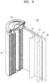
- a lithium secondary battery 20 includes a positive electrode 23, a negative electrode 22, and a separator 24.
- the positive electrode 23, the negative electrode 22, and the separator 24 are wound up or folded and accommodated in a battery case 25.
- an organic electrolytic solution is injected into the battery case 25 and the battery case 25 is sealed with a cap assembly 26 to complete the manufacture of the lithium secondary battery 20.
- the battery case 25 may be a cylindrical type, a rectangular type, a thin-film type, or the like.
- the lithium secondary battery 20 may be a thin-film type battery.
- the lithium secondary battery 20 may be a lithium ion battery.
- a battery assembly may be prepared by interposing the separator between the positive electrode and the negative electrode.
- the battery assembly is stacked in a bi-cell structure and impregnated with the organic electrolytic solution, and then the resultant is accommodated in a pouch and sealed, a lithium ion polymer battery is manufactured.
- a battery pack may be manufactured by stacking a plurality of battery assemblies and may be used in various devices that require high capacity and high output, such as in laptop computers, smartphones, and electric vehicles.
- the lithium secondary battery may be suitable for electric vehicles (EVs) due to excellent lifespan characteristics and rate-characteristics.
- the lithium secondary battery may be applied to hybrid electric vehicles such as plug-in hybrid electric vehicles (PHEVs).
- PHEVs plug-in hybrid electric vehicles
- the lithium secondary battery may also be used in the any device that stores a large amount of power, such as electric bicycles and electric tools.
- a positive active material slurry was prepared by mixing LiCoO 2 as a positive active material, polyvinylidene fluoride (PVdF) as a binder, and carbon black as a conductive material in N-methyl pyrrolidone as a solvent in a weight ratio of 97.7:1.0: 1.3.
- the positive active material slurry was coated on an Al current collector, dried, and rolled to prepare a positive electrode.
- a negative active material slurry was prepared by mixing graphite as a negative active material and a styrene butadiene rubber (SBR) as a binder in a weight ratio of 97.7:2.3 and water dispersing the mixture.
- the negative active material slurry was coated on a Cu current collector, dried, and rolled to prepare a negative electrode.
- SBR styrene butadiene rubber
- An electrolytic solution was prepared by dissolving LiPF 6 as a lithium salt in a mixed solvent of ethylene carbonate, ethylmethyl carbonate, and dimethyl carbonate mixed in a volume ratio of 30:40:20 to a concentration of 1.15 M.
- a lithium secondary battery was prepared according to a well-known process by using the positive electrode, the negative electrode, the electrolytic solution, and polyethylene (PE) coated with polyvinylidene fluoride (PVdF) as a separator.
- PE polyethylene
- PVdF polyvinylidene fluoride
- the lithium secondary battery was charged/discharged at 45 °C with constant current (CC)-constant voltage (CV) of 0.05 C and 3.4 V to a cut-off current of 0.035 C and discharged with a CC of 0.2 C to a cut-off voltage of 3.9 V for precharging.
- CC constant current
- CV constant voltage
- the lithium secondary battery prepared according to Example 1 was charged/discharged at 23 °C with a CC of 0.5 C to a cut-off voltage of 3.9 V for precharging.
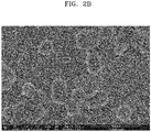
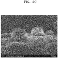
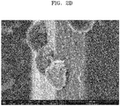
- the surface of the negative electrode of the lithium secondary battery prepared according to Example 1 was observed using a scanning electron microscope (SEM) and results are shown in FIGS. 2A to 2D .
- both a particulate passivation layer formed of particles having a diameter of about 100 to about 200 nm and a film-like passivation layer clearly distinguished therefrom are formed on the surface of the negative electrode of the lithium secondary battery according to an embodiment.
- the particulate passivation layer is formed of three-dimensional, spherical particles on the surface of the negative electrode and the other portion of the surface of the negative electrode is covered with the film-like passivation layer as a result of observation of the surface of the negative electrode of the lithium secondary battery according to an embodiment from the side.
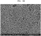
- the conventional lithium secondary battery includes a particulate passivation layer formed of particles having a diameter of about 25 to about 30 nm in an aggregated form rather than exact spherical shapes and a continuous film-like passivation layer is not distinguished from the aggregated form.
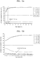
- compositions and thicknesses of the film-like passivation layer of the lithium secondary battery prepared according to Example 1 were analyzed by field emission Auger electron spectroscopy (FE-AES) after one cycle of charging and discharging and after 300 cycles of charging and discharging and results are shown in Table 1 below and FIGS. 4A and 4B .
- surface compositions and thicknesses of the film-like passivation layer of the conventional lithium secondary battery prepared according to Comparative Example 1 were analyzed by FE-AES after one cycle of charging and discharging and after 300 cycles of charging and discharging and results are shown in Table 12 below and FIGS. 5A and 5B .
- the unit “at%” refers to an atomic percent which is a unit of atomic concentration.
- the FE-AES was performed in the following manner.
- Particle 1 and Particle 2 show values respectively measured in particulate passivation layers of the passivation layer formed on the surface of the negative electrode and Film 1 and Film 2 show values respectively measured in film-like passivation layers of the passivation layer formed on the surface of the negative electrode.
- Particle 1 and Particle 2 refer to the particulate passivation layer after one cycle of charging and discharging
- “Film 1” and “Film 2” refer to the film-like passivation layer after one cycle of charging and discharging, each with respect to Example 1.
- Particle 1 and Particle 2 refer to the particulate passivation layer after one cycle of charging and discharging
- Finilm 1 and “Film 2” refer to the film-like passivation layer after one cycle of charging and discharging, each with respect to Comparative Example 1.
- P1, C1, N1, S1, O1, and F1 refer to the AT% of phosphorus, carbon, nitrogen, sulfur, oxygen, and fluorine, respectively, in the film-like passivation layer of Example 1 after one cycle of charging and discharging.
- P1, C1, N1, S1, O1, and F1 refer to the AT% of phosphorus, carbon, nitrogen, sulfur, oxygen, and fluorine, respectively, in the film-like passivation layer of Example 1 after 300 cycles of charging and discharging.
- FIG. 4A P1, C1, N1, S1, O1, and F1 refer to the AT% of phosphorus, carbon, nitrogen, sulfur, oxygen, and fluorine, respectively, in the film-like passivation layer of Example 1 after 300 cycles of charging and discharging.
- P1, C1, N1, S1, O1, and F1 refer to the AT% of phosphorus, carbon, nitrogen, sulfur, oxygen, and fluorine, respectively, in the film-like passivation layer of Comparative Example 1 after one cycle of charging and discharging.
- P1, C1, N1, S1, O1, and F1 refer to the AT% of phosphorus, carbon, nitrogen, sulfur, oxygen, and fluorine, respectively, in the film-like passivation layer of Comparative Example 1 after 300 cycles of charging and discharging.
- thicknesses of the film-like passivation layer of the lithium secondary battery of Example 1 were from about 20 to about 22 nm after one cycle of charging and discharging and from about 26 to about 32 nm after 300 cycles of charging and discharging. Thus, it was confirmed that the thickness of the film-like passivation layer was not considerably changed although the number of cycles increased.
- thicknesses of the passivation layer of the lithium secondary battery of Comparative Example 1 were from about 2 nm to about 4 nm after one cycle of charging and discharging indicating that the passivation layer was hardly formed and from about 30 nm to about 36 nm after 300 cycles of charging and discharging indicating that the thickness of the passivation layer was considerably changed.
- Thickness increase rates of the lithium secondary batteries prepared according to Example 1 and Comparative Example 1 with respect to the number of cycles of charging and discharging were measured and results thereof are shown in FIG. 6 .
- the thickness increase rate is defined as a percentage of a thickness of a battery after charging and discharging (T x ) to an initial thickness of the battery (T 1 ), i.e., [ ⁇ (T x -T 1 )/T 1 ⁇ 100%].
- an initial thickness increase rate of the lithium secondary battery of Comparative Example 1 was 10 % or more and the thickness increase rate steadily increased to 15 % or more as the number of cycles of charging and discharging increased, an initial thickness increase rate of the lithium secondary battery of Example 1 was about 5 % and the thickness increase rate was maintained at 10 % or less even after about 500 cycles of charging and discharging.
- the capacity characteristics of the batteries were evaluated using a charger/discharger.
- the batteries were charged at 25 °C with CC-CV of 0.5 C and 4.3 V to a cut-off current of 0.05 C and discharged with a CC of 0.7 C to a cut-off voltage of 3.0 V.
- Capacities of the batteries were identified at every 50 cycles at a rate of 0.2 C at a cut-off voltage of 3.0 V.
- the lithium secondary battery of Example 1 had better capacity characteristics with 90 % of the capacity maintained until about 600 cycles of charging and discharging and excellent lifespan characteristics in comparison with the lithium secondary battery of Comparative Example 1.
- Embodiments of the invention can provide a lithium secondary battery comprising: a positive electrode; a negative electrode; and an electrolyte interposed between the positive electrode and the negative electrode, wherein a passivation layer is formed on at least one portion of a surface of the negative electrode after one cycle of charging and discharging of the lithium secondary battery, and the passivation layer comprises a particulate passivation layer and a film-like passivation layer.
- a C-rate at which the one cycle of charging and discharging of the lithium secondary battery is performed may be from about 0.001 C to about 0.4 C.
- a temperature at which the one cycle of charging and discharging of the lithium secondary battery is performed may be from about 25 °C to about 80 °C.
- Embodiments of the invention can provide a method of manufacturing a lithium secondary comprising: providing a positive electrode; providing a negative electrode; providing an electrolyte interposed between the positive electrode and the negative electrode; and forming a passivation layer on at least one portion of a surface of the negative electrode after one cycle of charging and discharging of the lithium secondary battery, wherein the passivation layer comprises a particulate passivation layer and a film-like passivation layer.
- a C-rate at which the one cycle of charging and discharging of the lithium secondary battery is performed may be from about 0.001 C to about 0.4 C.
- a temperature at which the one cycle of charging and discharging of the lithium secondary battery is performed may be from about 25 °C to about 80 °C.
Landscapes
- Chemical & Material Sciences (AREA)
- Electrochemistry (AREA)
- General Chemical & Material Sciences (AREA)
- Chemical Kinetics & Catalysis (AREA)
- Engineering & Computer Science (AREA)
- Manufacturing & Machinery (AREA)
- Materials Engineering (AREA)
- Inorganic Chemistry (AREA)
- Physics & Mathematics (AREA)
- Condensed Matter Physics & Semiconductors (AREA)
- General Physics & Mathematics (AREA)
- Composite Materials (AREA)
- Secondary Cells (AREA)
- Battery Electrode And Active Subsutance (AREA)
Abstract
Description
- One or more embodiments relate to lithium secondary batteries including a passivation layer formed on a surface of a negative electrode.
- A lithium secondary battery generally includes a positive electrode, a negative electrode, and an electrolyte. When the electrolyte is brought into contact with active materials of the electrodes, oxidation and reduction reactions of components of the electrolyte occur. Although some products of these reactions are desorbed or eluted therefrom, others are deposited on the surface of the electrode to form a passivation layer on the surface of an active material.
- Since the behavior of the passivation layer is similar to that of a solid electrolyte, due to a very low electronic conductivity and a very high lithium ion conductivity, the passivation layer is also referred to as a solid electrolyte interphase (SEI) layer.
- One or more embodiments include a lithium secondary battery having a high initial efficiency and a high capacity during charging and discharging.
- One or more embodiments include a lithium secondary battery having a high capacity and a long lifespan by suppressing a thickness increase of the battery during charging and discharging. According to an aspect of the invention, there is provided a lithium secondary battery as set out in
claim 1. Preferred features of this aspect are set out inclaims 2 to 12. According to an aspect of the invention, there is provided a method of manufacturing a lithium secondary battery as set out in claim 13. Preferred features of this aspect are set out inclaims 14 and 15. - These and/or other aspects will become apparent and more readily appreciated from the following description of the embodiments, taken in conjunction with the accompanying drawings in which:
-
FIG. 1 is a scanning electron microscope (SEM) image of a passivation layer of a lithium secondary battery according to an embodiment; -
FIGS. 2A to 2D are SEM images of a passivation layer of a lithium secondary battery according to an embodiment; -
FIGS. 3A to 3C are SEM images of a passivation layer of a conventional lithium secondary battery; -
FIGS. 4A and 4B are graphs illustrating analysis results of surface compositions and thicknesses of a film-like passivation layer of a lithium secondary battery according to an embodiment after one cycle of charging and discharging and 300 cycles of charging and discharging analyzed by field emission Auger electron spectroscopy (FE-AES) respectively; -
FIGS. 5A and 5B are graphs illustrating FE-AES analysis results of surface compositions and thicknesses of a film-like passivation layer of a conventional lithium secondary battery after one cycle of charging and discharging and 300 cycles of charging and discharging respectively; -
FIG. 6 is a graph illustrating thickness increase rates of a lithium secondary battery according to an embodiment and a conventional lithium secondary battery with respect to the number of cycles; -
FIG. 7 is a graph illustrating capacity variations of a lithium secondary battery according to an embodiment and a conventional lithium secondary battery with respect to the number of cycles; and -
FIG. 8 is a diagram schematically illustrating a structure of a lithium secondary battery according to an embodiment. - Reference will now be made in detail to embodiments, examples of which are illustrated in the accompanying drawings, wherein like reference numerals refer to like elements throughout. In this regard, the present embodiments may have different forms and should not be construed as being limited to the descriptions set forth herein. Accordingly, the embodiments are merely described below, by referring to the figures, to explain aspects of the present description. As used herein, the term "and/or" includes any and all combinations of one or more of the associated listed items. Expressions such as "at least one of" when preceding a list of elements, modify the entire list of elements and do not modify the individual elements of the list.
- A lithium secondary battery according to exemplary embodiments will be described in detail with reference to the accompanying drawings.
- A lithium secondary battery according to an embodiment includes a positive electrode, a negative electrode, and an electrolyte interposed between the positive electrode and the negative electrode, wherein a passivation layer is formed on at least one portion of a surface of the negative electrode after one or more cycles of charging and discharging of the lithium secondary battery and the passivation layer includes a particulate passivation layer and a film-like passivation layer.
- The lithium secondary battery according to the embodiment may have excellent lifespan characteristics and high capacity by suppressing thickness changes in cells.
- According to an exemplary embodiment, a thickness of the film-like passivation layer may be 10 nm or greater. According to another exemplary embodiment, the thickness of the film-like passivation layer may be 15 nm or greater, for example, 20 nm or greater, without embodiments being limited thereto. For example, the thickness of the film-like passivation layer may be from about 10 nm to about 300 nm, for example from about 15 nm to about 150 nm, or from about 20 nm to about 80 nm, without embodiments being limited thereto.
- According to an exemplary embodiment, a thickness D1 of the film-like passivation layer may be 10 nm or greater, for example, 15 nm or greater, or 20 nm or greater after one cycle of charging and discharging of the lithium secondary battery, without embodiments being limited thereto. For example, the thickness D1 of the film-like passivation layer may be from about 10 nm to about 300 nm, for example from about 15 nm to about 150 nm, or from about 20 nm to about 80 nm after one cycle of charging and discharging of the lithium secondary battery, without embodiments being limited thereto.
- According to an exemplary embodiment, a ratio D300/D1 of a thickness D300 of the film-like passivation layer after 300 cycles of charging and discharging of the lithium secondary battery to a thickness D1 of the film-like passivation layer after one cycle of charging and discharging of the lithium secondary battery is from about 1.0 to 1.5, for example from about 1.0 to about 1.15, or from about 1.01 to about 1.1. That is, the lithium secondary battery may have long lifespan and high capacity due to small thickness changes in the passivation layer.
- According to an exemplary embodiment, the thickness of the particulate passivation layer may be from about 100 to about 600 nm, for example from about 100 to about 400 nm.
- According to another exemplary embodiment, the particulate passivation layer has a three-dimensional structure or a shape in which a plurality of spherical particles aggregate.
- According to an exemplary embodiment, the particulate passivation layer may include spherical particles having an average diameter of about 50 nm to about 500 nm, for example, about 100 nm to about 200 nm. When the average diameter of the particles of the particulate passivation layer satisfies the ranges described above, the lithium secondary battery may have excellent lifespan and capacity characteristics since a resistance increase in the battery is inhibited in comparison with a lithium secondary battery including a particulate passivation layer densely formed of smaller particles with a smaller average diameter and the lithium secondary battery may also have a less thickness increase in initial cells in comparison with a lithium secondary battery including a particulate passivation layer formed of larger particles with a larger average diameter. The average diameter may be determined by measuring the diameters of spherical particles on scanning electronic microscope (SEM) images.
- According to an exemplary embodiment, a ratio of the thickness of the particulate passivation layer to the thickness of the film-like passivation layer may be from about 20:1 to about 3:1, for example from about 15:1 to about 5:1. When the ratio of the thickness of the particulate passivation layer to the thickness of the film-like passivation layer of the lithium secondary battery satisfies the ranges described above, the particulate passivation layer is sufficiently grown, and thus oxidation and reduction reactions between the active material and the electrolyte may be efficiently inhibited.
- The above-described thicknesses of the passivation layer are values relatively estimated from sputtering results of Auger Electron Spectroscopy (AES) under discharging conditions of the lithium secondary battery.
- According to an exemplary embodiment, the passivation layer may include an organic compound, an inorganic compound, or any combination thereof. For example, the passivation layer may include but embodiments are not limited to: a hydrocarbon compound; an inorganic compound such as LiF and LiPF6 and a reduced form thereof; or an organic compound comprising C-O, C=O, or any combination thereof.
- According to an exemplary embodiment, the particulate passivation layer may include an inorganic compound. For example, the particulate passivation layer may include an inorganic compound including a fluorine atom, without embodiments being limited thereto.
- According to an exemplary embodiment, the particulate passivation layer may include an inorganic compound such as LiF and LiPF6 and a reduced form thereof, without embodiments being limited thereto.
- According to an exemplary embodiment, the film-like passivation layer may be formed of an organic compound.
- According to an exemplary embodiment, the passivation layer may be formed on at least 40 % by area, at least 55 % by area, for example at least 65 % by area, or at least 80 % by area of the surface of the negative electrode.
- According to another exemplary embodiment, the film-like passivation layer may be formed on at least 35 % by area, for example at least 50 % by area, or at least 65 % by area of the surface of the negative electrode.
- When the area of the passivation layer satisfies the ranges described above, oxidation and reduction reactions of the electrolyte do not proceed further and resistance of the passivation layer is maintained under a given level, and thus the lithium secondary battery may have excellent lifespan and capacity characteristics.
- According to an exemplary embodiment, a C-rate at which the one cycle of charging and discharging of the lithium secondary battery is performed is from about 0.001 C to about 0.4 C, for example from about 0.01 C to about 0.2 C.
- According to another exemplary embodiment, a temperature at which the one cycle of charging and discharging of the lithium secondary battery is performed is from about 25 °C to about 80 °C.
- In addition, a voltage at which the one cycle of charging and discharging of the lithium secondary battery is performed is from about 2.7 V to about 4.4 V, for example from about 3.0 V to about 4.3 V, without embodiments being limited thereto.
- When the above-described conditions for one cycle of charging and discharging of the lithium secondary battery are satisfied, the film-like passivation layer and the particulate passivation layer described above are formed, and thus sufficient battery capacity and long lifespan may be obtained. According to an exemplary embodiment, since the film-like passivation layer and the particulate passivation layer described above are formed at a low C-rate of about 0.01 C and a high temperature of about 60 °C among the initial charging and discharging conditions of the lithium secondary battery, high battery capacity and long lifespan may be obtained.
- The negative electrode according to an exemplary embodiment includes a negative current collector, and a negative active material layer formed on the negative current collector, wherein the passivation layer is formed on the negative active material layer. Materials used to form the negative current collector and the negative active material layer may be any materials selected with reference to manufacturing methods of lithium secondary batteries commonly used in the art and materials commonly used to form lithium secondary batteries which will be described later without limitation. For example, the negative current collector may include copper (Cu).
- According to an exemplary embodiment, the negative active material layer may include a carbonaceous negative active material. For example, the negative active material layer may include graphite.
- According to an exemplary embodiment, the electrolyte may include a lithium salt, a non-aqueous organic solvent, and an additive.
- According to an exemplary embodiment, the additive may include vinylene carbonate (VC), vinyl ethylene carbonate (VEC), fluoroethylene carbonate, and the like, without embodiments being limited thereto.
- Hereinafter, a general method of manufacturing a lithium secondary battery according to an embodiment and materials used to manufacture the lithium secondary battery will be exemplarily described. However, examples of the manufacturing method and materials used to form the lithium secondary battery are not limited thereto and any known methods and materials may also be applied thereto.
- For example, the lithium secondary battery may be manufactured according to the following method.
- First, a positive electrode is prepared.
- For example, a positive active material composition in which a positive active material, a conductive material, a binder, and a solvent are mixed is prepared. The positive active material composition is directly coated on a metal current collector to manufacture a positive electrode plate. Alternatively, the positive active material composition is cast on a separate support and a film separated from the support is laminated on a metal current collector to manufacture a positive electrode plate. However, the positive electrode of embodiments is not limited to the examples described above and may have various shapes.
- The positive active material may include a lithium-containing metal oxide and may further include any material commonly used in the art without limitation. For example, a composite oxide of lithium and a metal selected from cobalt (Co), manganese (Mn), nickel (Ni), and any combination thereof may be used. For example, a compound represented by any one of the following formulae LiaA1-bB1 bD1 2 (where 0.90≤a≤1.8 and 0≤b≤0.5); LiaE1-bB1 bO2-cD1 c (where 0.90≤a≤1.8, 0≤b≤0.5, and 0≤c≤0.05); LiE2-bB1 bO4-cD1 c (where 0≤b≤0.5 and 0≤c≤0.05); LiaNi1-b-cCobB1 cD1 α (where 0.90≤a≤1.8, 0≤b≤0.5, 0≤c≤0.05, and 0<α≤2); LiaNi1-b-cCobB1 cO2-αF1 α (where 0.90≤a≤1.8, 0≤b≤0.5, 0≤c≤0.05, and 0<α<2); LiaNi1-b-cCobB1 cO2-αF1 2 (where 0.90≤a≤1.8, 0≤b≤0.5, 0≤c≤0.05, and 0<α<2); LiaNi1-b-cMnbB1 cD1 α (where 0.90≤a≤1.8, 0≤b≤0.5, 0≤c≤0.05, and 0<α≤2); LiaNi1-b-cMnbB1 cO2-αF1 α (where 0.90≤a≤1.8, 0≤b≤0.5, 0≤c≤0.05, and 0<α<2); LiaNi1-b-cMnbB1 cO2-αF1 2 (where 0.90≤a≤1.8, 0≤b ≤0.5, 0≤c≤0.05, and 0<α<2); LiaNibEcGdO2 (where 0.90≤a≤1.8, 0≤b≤0.9, 0≤c≤0.5, and 0.001≤d≤0.1); LiaNibCocMndGeO2 (where 0.90≤a≤1.8, 0≤b≤0.9, 0≤c≤0.5, 0≤d≤0.5, and 0.001≤e≤0.1); LiaNiGbO2 (where 0.90≤a≤1.8 and 0.001≤b≤0.1); LiaCoGbO2 (where 0.90≤a≤1.8 and 0.001≤b≤0.1); LiaMnGbO2 (where 0.90≤a≤1.8 and 0.001≤b≤0.1); LiaMn2GbO4 (where 0.90≤a≤1.8 and 0.001≤b≤0.1); QO2; QS2; LiQS2; V2O5; LiV2O5; Lil1O2; LiNiVO4; Li(3-f)J2(PO4)3 (0≤f≤2); Li(3-f)Fe2(PO4)3 (0≤f≤2); and LiFePO4 may be used.
- In the formulae, A is Ni, Co, Mn, or any combination thereof; B is Al, Ni, Co, Mn, Cr, Fe, Mg, Sr, V, a rare earth element, or any combination thereof; D is O, F, S, P, or any combination thereof; E is Co, Mn, or any combination thereof; F is F, S, P, or any combination thereof; G is Al, Cr, Mn, Fe, Mg, La, Ce, Sr, V, or any combination thereof; Q is Ti, Mo, Mn, or any combination thereof; I is Cr, V, Fe, Sc, Y, or any combination thereof; and J is V, Cr, Mn, Co, Ni, Cu, or any combination thereof.
- For example, LiCoO2, LiMnxO2x (x=1, 2), LiNi1-xMnxO2x (0<x<1), LiNi1-x-yCoxMnyO2 (0≤x≤0.5 and 0≤y≤0.5), LiFePO4, and the like may be used.
- The compounds listed above may have a coating layer on the surface thereof or a mixture of a compound with no coating layer and a compound having a coating layer may also be used. The coating layer may include a compound of a coating element, such as an oxide, hydroxide, oxyhydroxide, oxycarbonate, or hydroxycarbonate of the coating element. The compound constituting the coating layer may be amorphous or crystalline. Examples of the coating element contained in the coating layer may be Mg, Al, Co, K, Na, Ca, Si, Ti, V, Sn, Ge, Ga, B, As, Zr, or a mixture thereof. The coating layer may be formed on the compound by using the coating element by any coating method, which does not adversely affect physical properties of the positive active material (e.g., spray coating and immersing). These methods are obvious to those of ordinary skill in the art, and thus detailed descriptions thereof will not be given.
- The conductive material may be, but not limited to, carbon black, graphite particulates, or the like and any material commonly used in the art as a conductive material may also be used.
- The binder may be a vinylidene fluoride/hexafluoropropylene copolymer, polyvinylidene fluoride (PVdF), polyacrylonitrile, polymethylmethacrylate, polytetrafluoroethylene and any mixture thereof, a styrene butadiene rubber polymer, or the like. However, the binder is not limited thereto in embodiments and any material commonly used in the art as a binder may also be used.
- The solvent may be N-methyl pyrrolidone, acetone, water, or the like. However, the solvent is not limited thereto in embodiments and any material commonly used in the art as a solvent may also be used.
- The positive active material, the conductive material, the binder, and the solvent may be used in amounts commonly used in lithium batteries. At least one of the conductive material, the binder, and the solvent may not be used according to use and configuration of the lithium secondary battery.
- Next, a negative electrode is prepared.
- For example, a negative active material, a conductive material, a binder, and a solvent are mixed to prepare a negative active material composition. The negative active material composition is directly coated on a metal current collector and dried to manufacture a negative electrode plate. Alternatively, the negative active material composition is cast on a separate support and a film separated from the support is laminated on a metal current collector to manufacture a negative electrode plate.
- The negative active material may be any material commonly used as a negative active material in lithium secondary batteries. For example, the negative active material may include at least one selected from lithium metal, a metal that is alloyable with lithium, a transition metal oxide, a non-transition metal oxide, and a carbonaceous material.
- For example, the metal alloyable with lithium may be Si, Sn, Al, Ge, Pb, Bi, Sb, an Si-Y alloy (where Y is alkali metal, alkali earth metal, Group XIII element, Group XIV element, transition metal, rare earth element, or a combination thereof (except for Si)), an Sn-Y alloy (where Y is alkali metal, alkali earth metal, Group XIII element, Group XIV element, transition metal, rare earth element, or a combination thereof (except for Sn)), or the like. The element Y may be Mg, Ca, Sr, Ba, Ra, Sc, Y, Ti, Zr, Hf, Rf, V, Nb, Ta, Db, Cr, Mo, W, Sg, Tc, Re, Bh, Fe, Pb, Ru, Os, Hs, Rh, Ir, Pd, Pt, Cu, Ag, Au, Zn, Cd, B, Al, Ga, Sn, In, Tl, Ge, P, As, Sb, Bi, S, Se, or Te.
- For example, the transition metal oxide may be lithium titanium oxide, vanadium oxide, lithium vanadium oxide, or the like.
- For example, the non-transition metal oxide may be SnO2, SiOx (0<x<2), or the like.
- The carbonaceous material may be crystalline carbon, amorphous carbon, or any mixture thereof. The crystalline carbon may be natural graphite or artificial graphite in amorphous, plate, flake, spherical or fibrous form. The amorphous carbon may be soft carbon (carbon sintered at low temperatures), hard carbon, meso-phase pitch carbides, sintered coke, or the like.
- The conductive material, the binder, and the solvent used in the negative active material composition may be the same as those used in the positive active material composition.
- The amounts of the negative active material, the conductive material, the binder, and the solvent are amounts commonly used in the art in the manufacture of lithium batteries. At least one of the conductive material, the binder, and the solvent may not be used according to use and configuration of the lithium secondary battery.
- Next, a separator to be interposed between the positive electrode and the negative electrode is prepared.
- The separator may be any separator commonly used in lithium batteries. A separator that has low resistance to migration of ions of an electrolyte and excellent electrolytic solution-retaining ability may be used. For example, the separator may be glass fiber, polyester, Teflon, polyethylene, polypropylene, polytetrafluoroethylene (PTFE), or a combination thereof, each of which may be a nonwoven fabric or a woven fabric. For example, a windable separator such as polyethylene or polypropylene may be used in lithium-ion batteries. A separator with an excellent organic electrolyte retaining capability may be used in lithium-ion polymer batteries. For example, the separator may be prepared according to the following method.
- A polymer resin, a filler, and a solvent are mixed to prepare a separator composition. The separator composition may be directly coated on the electrode and dried to form a separator. Alternatively, the separator composition may be cast on a support and dried and a separator film separated from the support may be laminated on the electrode to form a separator.
- The polymer resin used to manufacture the separator is not particularly limited and may be any material commonly used as a binder for electrode plates. For example, the polymer resin may be a vinylidenefluoride/hexafluoropropylene copolymer, polyvinylidene fluoride (PVdF), polyacrylonitrile, polymethylmethacrylate and any mixture thereof.
- Next, an electrolyte is prepared.
- For example, the electrolyte may be an organic electrolytic solution. Also, the electrolyte may be a solid. For example, the electrolyte may be boron oxide or lithium oxynitride. However, the electrolyte is not limited thereto in embodiments and any material commonly used in the art as a solid electrolyte may also be used. The solid electrolyte may be formed on the negative electrode by sputtering, or the like.
- For example, the organic electrolytic solution may be prepared by dissolving a lithium salt in an organic solvent.
- The organic solvent may be any organic solvent commonly used in the art. For example, the organic solvent may be propylene carbonate, ethylene carbonate, fluoroethylene carbonate, butylene carbonate, dimethyl carbonate, diethyl carbonate, methylethyl carbonate, methylpropyl carbonate, ethylpropyl carbonate, methylisopropyl carbonate, dipropyl carbonate, dibutyl carbonate, benzonitrile, acetonitrile, tetrahydrofuran, 2-methyltetrahydrofuran, γ-butyrotactone, dioxolane, 4-methyldioxolane, N,N-dimethyl formamide, dimethyl acetamide, dimethylsulfoxide, dioxane, 1,2-dimethoxyethane, sulfolane, dichloroethane, chlorobenzene, nitrobenzene, diethylene glycol, dimethyl ether, or any mixture thereof.
- The lithium salt may be any lithium salt commonly used in the art. For example, the lithium salt may be LiPF6, LiBF4, LiSbF6, LiAsF6, LiClO4, LiCF3SO3, Li(CF3SO2)2N, LiC4F9SO3, LiAlO2, LiAlCl4, LiN(CxF2x+1SO2)(CyF2y+1SO2) (where x and y are natural number), LiCI, Lil, or any mixture thereof.
- As illustrated in
FIG. 8 , a lithiumsecondary battery 20 includes apositive electrode 23, anegative electrode 22, and aseparator 24. Thepositive electrode 23, thenegative electrode 22, and theseparator 24 are wound up or folded and accommodated in abattery case 25. Next, an organic electrolytic solution is injected into thebattery case 25 and thebattery case 25 is sealed with acap assembly 26 to complete the manufacture of the lithiumsecondary battery 20. - The
battery case 25 may be a cylindrical type, a rectangular type, a thin-film type, or the like. For example, the lithiumsecondary battery 20 may be a thin-film type battery. - The lithium
secondary battery 20 may be a lithium ion battery. - A battery assembly may be prepared by interposing the separator between the positive electrode and the negative electrode. When the battery assembly is stacked in a bi-cell structure and impregnated with the organic electrolytic solution, and then the resultant is accommodated in a pouch and sealed, a lithium ion polymer battery is manufactured.
- Also, a battery pack may be manufactured by stacking a plurality of battery assemblies and may be used in various devices that require high capacity and high output, such as in laptop computers, smartphones, and electric vehicles.
- In addition, the lithium secondary battery may be suitable for electric vehicles (EVs) due to excellent lifespan characteristics and rate-characteristics. For example, the lithium secondary battery may be applied to hybrid electric vehicles such as plug-in hybrid electric vehicles (PHEVs). The lithium secondary battery may also be used in the any device that stores a large amount of power, such as electric bicycles and electric tools.
- One or more embodiments will be described in more detail with reference to the following examples and comparative examples. However, these examples and comparative examples are not intended to limit the scope of the one or more embodiments.
- A positive active material slurry was prepared by mixing LiCoO2 as a positive active material, polyvinylidene fluoride (PVdF) as a binder, and carbon black as a conductive material in N-methyl pyrrolidone as a solvent in a weight ratio of 97.7:1.0: 1.3. The positive active material slurry was coated on an Al current collector, dried, and rolled to prepare a positive electrode.
- A negative active material slurry was prepared by mixing graphite as a negative active material and a styrene butadiene rubber (SBR) as a binder in a weight ratio of 97.7:2.3 and water dispersing the mixture. The negative active material slurry was coated on a Cu current collector, dried, and rolled to prepare a negative electrode.
- An electrolytic solution was prepared by dissolving LiPF6 as a lithium salt in a mixed solvent of ethylene carbonate, ethylmethyl carbonate, and dimethyl carbonate mixed in a volume ratio of 30:40:20 to a concentration of 1.15 M.
- A lithium secondary battery was prepared according to a well-known process by using the positive electrode, the negative electrode, the electrolytic solution, and polyethylene (PE) coated with polyvinylidene fluoride (PVdF) as a separator.
- The lithium secondary battery was charged/discharged at 45 °C with constant current (CC)-constant voltage (CV) of 0.05 C and 3.4 V to a cut-off current of 0.035 C and discharged with a CC of 0.2 C to a cut-off voltage of 3.9 V for precharging.
- The lithium secondary battery prepared according to Example 1 was charged/discharged at 23 °C with a CC of 0.5 C to a cut-off voltage of 3.9 V for precharging.
- The surface of the negative electrode of the lithium secondary battery prepared according to Example 1 was observed using a scanning electron microscope (SEM) and results are shown in
FIGS. 2A to 2D . - Referring to
FIGS. 2A and2B , it was confirmed that both a particulate passivation layer formed of particles having a diameter of about 100 to about 200 nm and a film-like passivation layer clearly distinguished therefrom are formed on the surface of the negative electrode of the lithium secondary battery according to an embodiment. - Also, referring to
FIGS. 2C and2D , it was confirmed that the particulate passivation layer is formed of three-dimensional, spherical particles on the surface of the negative electrode and the other portion of the surface of the negative electrode is covered with the film-like passivation layer as a result of observation of the surface of the negative electrode of the lithium secondary battery according to an embodiment from the side. - On the contrary, referring to
FIGS. 3A to 3C , it was confirmed that the conventional lithium secondary battery includes a particulate passivation layer formed of particles having a diameter of about 25 to about 30 nm in an aggregated form rather than exact spherical shapes and a continuous film-like passivation layer is not distinguished from the aggregated form. - Surface compositions and thicknesses of the film-like passivation layer of the lithium secondary battery prepared according to Example 1 were analyzed by field emission Auger electron spectroscopy (FE-AES) after one cycle of charging and discharging and after 300 cycles of charging and discharging and results are shown in Table 1 below and
FIGS. 4A and 4B . In addition, surface compositions and thicknesses of the film-like passivation layer of the conventional lithium secondary battery prepared according to Comparative Example 1 were analyzed by FE-AES after one cycle of charging and discharging and after 300 cycles of charging and discharging and results are shown in Table 12 below andFIGS. 5A and 5B . The unit "at%" refers to an atomic percent which is a unit of atomic concentration. - Particularly, the FE-AES was performed in the following manner.
- (1) Discharge and disassemble a cell to be analyzed in a moisture-reduced atmosphere (dry room or glove box).
- (2) Wash a negative electrode of the cell in the glove box using dimethyl carbonate (DMC) for 10 minutes or more to remove remaining electrolytic solution.
- (3) Collect a portion of the surface of the washed negative electrode substrate as a sample
- (4) Mount the sample in an FE-AES device in an air-shielded state and perform sputtering a portion of the film-like passivation layer where no particulate passivation layer is found.
- (5) Measure thickness of a portion of the film-like passivation layer where a carbon composition is saturated (about 90 % or more) after sputtering and convert the thickness of the passivation layer based on an SiO2 etching rate.
- In Tables 1 and 2 below,
Particle 1 andParticle 2 show values respectively measured in particulate passivation layers of the passivation layer formed on the surface of the negative electrode andFilm 1 andFilm 2 show values respectively measured in film-like passivation layers of the passivation layer formed on the surface of the negative electrode. For example, in Table 1, "Particle 1" and "Particle 2" refer to the particulate passivation layer after one cycle of charging and discharging, and "Film 1" and "Film 2" refer to the film-like passivation layer after one cycle of charging and discharging, each with respect to Example 1. Additionally, in Table 2, "Particle 1" and "Particle 2" refer to the particulate passivation layer after one cycle of charging and discharging, and "Film 1" and "Film 2" refer to the film-like passivation layer after one cycle of charging and discharging, each with respect to Comparative Example 1. - In
FIG. 4A , P1, C1, N1, S1, O1, and F1 refer to the AT% of phosphorus, carbon, nitrogen, sulfur, oxygen, and fluorine, respectively, in the film-like passivation layer of Example 1 after one cycle of charging and discharging. InFIG. 4B , P1, C1, N1, S1, O1, and F1 refer to the AT% of phosphorus, carbon, nitrogen, sulfur, oxygen, and fluorine, respectively, in the film-like passivation layer of Example 1 after 300 cycles of charging and discharging. InFIG. 5A , P1, C1, N1, S1, O1, and F1 refer to the AT% of phosphorus, carbon, nitrogen, sulfur, oxygen, and fluorine, respectively, in the film-like passivation layer of Comparative Example 1 after one cycle of charging and discharging. InFIG. 5B , P1, C1, N1, S1, O1, and F1 refer to the AT% of phosphorus, carbon, nitrogen, sulfur, oxygen, and fluorine, respectively, in the film-like passivation layer of Comparative Example 1 after 300 cycles of charging and discharging.Table 1 C (at%) O (at%) F (at%) S (at%) Total (at%) Particle 165.5 24.1 5.8 4.6 100 Particle 265.0 25.9 5.0 4.1 100 Film 168.7 23.3 4.4 3.6 100 Film 268.8 24.6 4.4 2.2 100 Table 2 C (at%) O (at%) F (at%) S (at%) P (at%) Total (at%) Particle 162.6 21.7 8.1 4.3 3.2 100 Particle 263.0 21.5 7.6 4.5 3.4 100 Film 167.5 23.3 6.3 3.0 - 100 Film 267.3 23.5 6.4 2.8 - 100 - Referring to the compositions of Table 1 and
FIGS. 4A and 4B , thicknesses of the film-like passivation layer of the lithium secondary battery of Example 1 were from about 20 to about 22 nm after one cycle of charging and discharging and from about 26 to about 32 nm after 300 cycles of charging and discharging. Thus, it was confirmed that the thickness of the film-like passivation layer was not considerably changed although the number of cycles increased. - On the contrary, referring to the compositions of Table 2 and
FIGS. 5A and 5B , thicknesses of the passivation layer of the lithium secondary battery of Comparative Example 1 were from about 2 nm to about 4 nm after one cycle of charging and discharging indicating that the passivation layer was hardly formed and from about 30 nm to about 36 nm after 300 cycles of charging and discharging indicating that the thickness of the passivation layer was considerably changed. - Thickness increase rates of the lithium secondary batteries prepared according to Example 1 and Comparative Example 1 with respect to the number of cycles of charging and discharging were measured and results thereof are shown in
FIG. 6 . The thickness increase rate is defined as a percentage of a thickness of a battery after charging and discharging (Tx) to an initial thickness of the battery (T1), i.e., [{(Tx-T1)/T1}×100%]. - Referring to
FIG. 6 , it was confirmed that while an initial thickness increase rate of the lithium secondary battery of Comparative Example 1 was 10 % or more and the thickness increase rate steadily increased to 15 % or more as the number of cycles of charging and discharging increased, an initial thickness increase rate of the lithium secondary battery of Example 1 was about 5 % and the thickness increase rate was maintained at 10 % or less even after about 500 cycles of charging and discharging. - Capacity characteristics of lithium secondary batteries of Example 1 and Comparative Example 1 with respect to the number of cycles of charging and discharging were evaluated and results thereof are shown in
FIG. 7 . - The capacity characteristics of the batteries were evaluated using a charger/discharger. The batteries were charged at 25 °C with CC-CV of 0.5 C and 4.3 V to a cut-off current of 0.05 C and discharged with a CC of 0.7 C to a cut-off voltage of 3.0 V. Capacities of the batteries were identified at every 50 cycles at a rate of 0.2 C at a cut-off voltage of 3.0 V.
- Referring to
FIG. 7 , it was confirmed that the lithium secondary battery of Example 1 had better capacity characteristics with 90 % of the capacity maintained until about 600 cycles of charging and discharging and excellent lifespan characteristics in comparison with the lithium secondary battery of Comparative Example 1. - Embodiments of the invention can provide a lithium secondary battery comprising: a positive electrode; a negative electrode; and an electrolyte interposed between the positive electrode and the negative electrode, wherein a passivation layer is formed on at least one portion of a surface of the negative electrode after one cycle of charging and discharging of the lithium secondary battery, and the passivation layer comprises a particulate passivation layer and a film-like passivation layer.
- A C-rate at which the one cycle of charging and discharging of the lithium secondary battery is performed may be from about 0.001 C to about 0.4 C.
- A temperature at which the one cycle of charging and discharging of the lithium secondary battery is performed may be from about 25 °C to about 80 °C.
- Embodiments of the invention can provide a method of manufacturing a lithium secondary comprising: providing a positive electrode; providing a negative electrode; providing an electrolyte interposed between the positive electrode and the negative electrode; and forming a passivation layer on at least one portion of a surface of the negative electrode after one cycle of charging and discharging of the lithium secondary battery, wherein the passivation layer comprises a particulate passivation layer and a film-like passivation layer.
- A C-rate at which the one cycle of charging and discharging of the lithium secondary battery is performed may be from about 0.001 C to about 0.4 C.
- A temperature at which the one cycle of charging and discharging of the lithium secondary battery is performed may be from about 25 °C to about 80 °C.
- It should be understood that embodiments described herein should be considered in a descriptive sense only and not for purposes of limitation. Descriptions of features or aspects within each embodiment should typically be considered as available for other similar features or aspects in other embodiments.
- While one or more embodiments have been described with reference to the figures, it will be understood by those of ordinary skill in the art that various changes in form and details may be made therein without departing from the scope as defined by the following claims.
Claims (15)
- A lithium secondary battery comprising:a positive electrode;a negative electrode; andan electrolyte interposed between the positive electrode and the negative electrode,wherein a passivation layer is formed on at least one portion of a surface of the negative electrode after one cycle of charging and discharging of the lithium secondary battery, andwherein the passivation layer comprises a particulate passivation layer and a film-like passivation layer.
- The lithium secondary battery of claim 1, wherein a thickness of the film-like passivation layer is 10 nm or greater.
- The lithium secondary battery of claim 1 or 2, wherein a ratio D300/D1 of a thickness D300 of the film-like passivation layer after 300 cycles of charging and discharging of the lithium secondary battery to a thickness D1 of the film-like passivation layer after one cycle of charging and discharging of the lithium secondary battery is from about 1.0 to about 1.5.
- The lithium secondary battery of any one of claims 1 to 3, wherein a thickness of the particulate passivation layer is from about 100 nm to about 600 nm.
- The lithium secondary battery of any one of claims 1 to 4, wherein the particulate passivation layer comprises spherical particles having an average diameter of about 50 nm to about 500 nm.
- The lithium secondary battery of any one of claims 1 to 5, wherein a ratio of a thickness of the particulate passivation layer to a thickness of the film-like passivation layer is from about 20:1 to about 3:1.
- The lithium secondary battery of any one of claims 1 to 6, wherein the particulate passivation layer comprises an inorganic compound.
- The lithium secondary battery of any one of claims 1 to 7, wherein the passivation layer is formed on at least 40 % by area of the surface of the negative electrode; and/or
wherein the film-like passivation layer is formed on at least 35 % by area of the surface of the negative electrode. - The lithium secondary battery of any one of claims 1 to 8, wherein a C-rate at which the one cycle of charging and discharging of the lithium secondary battery is performed is from about 0.001 C to about 0.4 C.
- The lithium secondary battery of any one of claims 1 to 9, wherein a temperature at which the one cycle of charging and discharging of the lithium secondary battery is performed is from about 25 °C to about 80 °C.
- The lithium secondary battery of any one of claims 1 to 9, wherein the negative electrode comprises: a negative current collector; and a negative active material layer formed on the negative current collector, wherein the passivation layer is formed on the negative active material layer;
optionally wherein the negative active material layer comprises a carbonaceous negative active material. - The lithium secondary battery of any one of claims 1 to 11, wherein the electrolyte comprises a lithium salt, a non-aqueous organic solvent, and an additive;
optionally wherein the additive comprises vinylene carbonate (VC), vinyl ethylene carbonate (VEC), or fluoroethylene carbonate. - A method of manufacturing a lithium secondary battery comprising:forming a lithium secondary battery by providing a positive electrode, providing a negative electrode, and providing an electrolyte interposed between the positive electrode and the negative electrode; andforming a passivation layer on at least one portion of a surface of the negative electrode after one cycle of charging and discharging of the lithium secondary battery, wherein the passivation layer comprises a particulate passivation layer and a film-like passivation layer.
- The method of claim 13, wherein a C-rate at which the one cycle of charging and discharging of the lithium secondary battery is performed is from about 0.001 C to about 0.4 C.
- The method of claim 13 or 14, wherein a temperature at which the one cycle of charging and discharging of the lithium secondary battery is performed is from about 25 °C to about 80 °C.
Applications Claiming Priority (1)
| Application Number | Priority Date | Filing Date | Title |
|---|---|---|---|
| KR1020170036189A KR20180107620A (en) | 2017-03-22 | 2017-03-22 | Lithium secondary battery |
Publications (2)
| Publication Number | Publication Date |
|---|---|
| EP3379617A1 true EP3379617A1 (en) | 2018-09-26 |
| EP3379617B1 EP3379617B1 (en) | 2021-11-10 |
Family
ID=61749958
Family Applications (1)
| Application Number | Title | Priority Date | Filing Date |
|---|---|---|---|
| EP18163167.2A Active EP3379617B1 (en) | 2017-03-22 | 2018-03-21 | Lithium secondary battery |
Country Status (4)
| Country | Link |
|---|---|
| US (1) | US20180277851A1 (en) |
| EP (1) | EP3379617B1 (en) |
| KR (2) | KR20180107620A (en) |
| CN (1) | CN108630895B (en) |
Families Citing this family (2)
| Publication number | Priority date | Publication date | Assignee | Title |
|---|---|---|---|---|
| US12087949B2 (en) * | 2019-11-13 | 2024-09-10 | Enevate Corporation | Sacrificial salts in Li-rich, defect anti-fluorite compounds in cathodes for prelithiation in lithium ion batteries |
| DE102024110213A1 (en) | 2024-01-31 | 2025-07-31 | GM Global Technology Operations LLC | Process for producing preactivated lithium transition metal oxides for rechargeable batteries that cycle lithium ions |
Citations (3)
| Publication number | Priority date | Publication date | Assignee | Title |
|---|---|---|---|---|
| JP2002329529A (en) * | 2000-09-06 | 2002-11-15 | Toshiba Corp | Non-aqueous electrolyte secondary battery |
| JP2005071697A (en) * | 2003-08-21 | 2005-03-17 | Toshiba Corp | First charging method of non-aqueous electrolyte secondary battery |
| US20120208087A1 (en) * | 2010-05-18 | 2012-08-16 | Taisuke Yamamoto | Lithium secondary battery |
Family Cites Families (15)
| Publication number | Priority date | Publication date | Assignee | Title |
|---|---|---|---|---|
| ZA963605B (en) * | 1995-06-07 | 1996-11-19 | Duracell Inc | Process for improving lithium ion cell |
| JP3718467B2 (en) * | 2001-03-28 | 2005-11-24 | 株式会社東芝 | Non-aqueous electrolyte and non-aqueous electrolyte secondary battery |
| JP2003217667A (en) * | 2002-01-16 | 2003-07-31 | Japan Storage Battery Co Ltd | Non-aqueous electrolyte secondary battery |
| US20060115738A1 (en) * | 2004-12-01 | 2006-06-01 | Sergiy Sazhin | Lithium-fluorinated carbon cells |
| US8920981B2 (en) * | 2008-04-08 | 2014-12-30 | California Institute Of Technology | Lithium ion electrolytes and lithium ion cells with good low temperature performance |
| CN101826635A (en) * | 2010-04-09 | 2010-09-08 | 广州天赐高新材料股份有限公司 | Polymer electrolyte for lithium battery and manufacturing method of battery thereof |
| JP5621505B2 (en) * | 2010-10-21 | 2014-11-12 | ソニー株式会社 | Electrolyte and secondary battery |
| CN102064344A (en) * | 2010-12-21 | 2011-05-18 | 东莞市杉杉电池材料有限公司 | Novel electrolyte for power battery |
| JP5836601B2 (en) * | 2011-02-03 | 2015-12-24 | 株式会社東芝 | Nonaqueous electrolyte secondary battery |
| KR101201807B1 (en) * | 2011-08-31 | 2012-11-15 | 삼성에스디아이 주식회사 | Lithium secondary battery |
| JP5924552B2 (en) * | 2011-11-24 | 2016-05-25 | トヨタ自動車株式会社 | Non-aqueous electrolyte secondary battery and manufacturing method thereof |
| US9531002B2 (en) * | 2012-03-28 | 2016-12-27 | Sharp Laboratories Of America, Inc. | Transition metal cyanometallate cathode battery with metal plating anode |
| KR101683206B1 (en) * | 2012-04-30 | 2016-12-06 | 삼성에스디아이 주식회사 | Negative electrode for rechargeable lithium battery and rechargeable lithium battery including the same |
| CN103268956B (en) * | 2013-05-18 | 2015-10-21 | 山东鸿正电池材料科技有限公司 | A kind of nonaqueous electrolytic solution for high-voltage lithium ion batteries |
| ES2686822T3 (en) * | 2014-05-23 | 2018-10-22 | Solvay Sa | Non-aqueous electrolytic compositions comprising cyclic sulfates and lithium borates |
-
2017
- 2017-03-22 KR KR1020170036189A patent/KR20180107620A/en not_active Ceased
-
2018
- 2018-03-21 US US15/927,903 patent/US20180277851A1/en not_active Abandoned
- 2018-03-21 EP EP18163167.2A patent/EP3379617B1/en active Active
- 2018-03-22 CN CN201810238880.4A patent/CN108630895B/en active Active
-
2021
- 2021-11-26 KR KR1020210166132A patent/KR102460959B1/en active Active
Patent Citations (3)
| Publication number | Priority date | Publication date | Assignee | Title |
|---|---|---|---|---|
| JP2002329529A (en) * | 2000-09-06 | 2002-11-15 | Toshiba Corp | Non-aqueous electrolyte secondary battery |
| JP2005071697A (en) * | 2003-08-21 | 2005-03-17 | Toshiba Corp | First charging method of non-aqueous electrolyte secondary battery |
| US20120208087A1 (en) * | 2010-05-18 | 2012-08-16 | Taisuke Yamamoto | Lithium secondary battery |
Also Published As
| Publication number | Publication date |
|---|---|
| KR20180107620A (en) | 2018-10-02 |
| CN108630895B (en) | 2022-04-05 |
| KR20210149667A (en) | 2021-12-09 |
| US20180277851A1 (en) | 2018-09-27 |
| KR102460959B1 (en) | 2022-10-31 |
| EP3379617B1 (en) | 2021-11-10 |
| CN108630895A (en) | 2018-10-09 |
Similar Documents
| Publication | Publication Date | Title |
|---|---|---|
| US12406989B2 (en) | Composite cathode active material, cathode and lithium battery including the same, and method of preparing the composite cathode active material | |
| US10622631B2 (en) | Negative active material, lithium secondary battery including the material, and method of manufacturing the material | |
| EP3327834B1 (en) | Composite cathode active material, cathode and lithium battery containing the same, and method of preparing the composite cathode active material | |
| KR102183996B1 (en) | Positive active material and manufacturing method thereof, positive electrode and lithium battery containing the material | |
| KR102519441B1 (en) | Composite negative electrode active material for lithium secondary battery, an anode comprising the same, and the lithium secondary battery comprising the anode | |
| CN103094538B (en) | Negative active core-shell material and preparation method thereof, negative electrode and lithium battery | |
| US8999579B2 (en) | Surface treated anode active material and method of making the same, anode including the same, and lithium battery including the same | |
| KR102184372B1 (en) | Composite cathode active material, preparation method thereof, and cathode and lithium battery containing the same | |
| US10079384B2 (en) | Composite cathode active material, cathode and lithium battery including the composite cathode active material, and method of preparing the composite cathode active material | |
| KR102473532B1 (en) | Positive active material, and positive electrode and lithium battery containing the material | |
| EP2698849A1 (en) | Composite anode active material, anode and lithium battery comprising the material, and method of preparing the same | |
| KR102161625B1 (en) | Negative electrode, lithium battery including the same and method of manufacture of lithium battery | |
| KR101775544B1 (en) | Positive electrode for rechargable lithium battery and rechargable lithium battery including the same | |
| KR20210007273A (en) | Composite anode active material, and Anode and Lithium secondary battery comprising the same | |
| US20130260252A1 (en) | Composite electrode active material, electrode and lithium battery containing the composite electrode active material, and method of preparing the composite electrode active material | |
| KR102256295B1 (en) | Negative active material, negative electrode and lithium secondary battery including the same, and method of preparing the negative active material | |
| EP3923379A1 (en) | Composite cathode active material, cathode including the same, lithium battery employing the cathode, and preparation method thereof | |
| KR102246770B1 (en) | Negative active material, lithium battery including the same, and method of preparing the negative active material | |
| CN109314271B (en) | Lithium battery | |
| US10290862B2 (en) | Composite cathode active material, cathode and lithium battery including the composite cathode active material, and method of preparing the composite cathode active material | |
| KR20160005555A (en) | Lithium battery | |
| EP2985824A1 (en) | Cathode material, cathode including the same, and lithium battery including the cathode | |
| KR102460959B1 (en) | Lithium secondary battery | |
| KR20200133704A (en) | Lithium battery | |
| KR102273781B1 (en) | Negative active material and preparation method thereof |
Legal Events
| Date | Code | Title | Description |
|---|---|---|---|
| PUAI | Public reference made under article 153(3) epc to a published international application that has entered the european phase |
Free format text: ORIGINAL CODE: 0009012 |
|
| STAA | Information on the status of an ep patent application or granted ep patent |
Free format text: STATUS: REQUEST FOR EXAMINATION WAS MADE |
|
| 17P | Request for examination filed |
Effective date: 20180321 |
|
| AK | Designated contracting states |
Kind code of ref document: A1 Designated state(s): AL AT BE BG CH CY CZ DE DK EE ES FI FR GB GR HR HU IE IS IT LI LT LU LV MC MK MT NL NO PL PT RO RS SE SI SK SM TR |
|
| AX | Request for extension of the european patent |
Extension state: BA ME |
|
| STAA | Information on the status of an ep patent application or granted ep patent |
Free format text: STATUS: EXAMINATION IS IN PROGRESS |
|
| 17Q | First examination report despatched |
Effective date: 20190514 |
|
| GRAP | Despatch of communication of intention to grant a patent |
Free format text: ORIGINAL CODE: EPIDOSNIGR1 |
|
| STAA | Information on the status of an ep patent application or granted ep patent |
Free format text: STATUS: GRANT OF PATENT IS INTENDED |
|
| RIC1 | Information provided on ipc code assigned before grant |
Ipc: H01M 4/1393 20100101AFI20210528BHEP Ipc: H01M 10/04 20060101ALI20210528BHEP Ipc: H01M 10/0525 20100101ALI20210528BHEP Ipc: H01M 10/0567 20100101ALI20210528BHEP Ipc: H01M 10/058 20100101ALI20210528BHEP Ipc: H01M 4/04 20060101ALI20210528BHEP Ipc: H01M 4/13 20100101ALI20210528BHEP Ipc: H01M 4/139 20100101ALI20210528BHEP Ipc: H01M 10/44 20060101ALI20210528BHEP Ipc: H01M 4/133 20100101ALN20210528BHEP Ipc: H01M 4/587 20100101ALN20210528BHEP |
|
| INTG | Intention to grant announced |
Effective date: 20210628 |
|
| GRAS | Grant fee paid |
Free format text: ORIGINAL CODE: EPIDOSNIGR3 |
|
| GRAA | (expected) grant |
Free format text: ORIGINAL CODE: 0009210 |
|
| STAA | Information on the status of an ep patent application or granted ep patent |
Free format text: STATUS: THE PATENT HAS BEEN GRANTED |
|
| AK | Designated contracting states |
Kind code of ref document: B1 Designated state(s): AL AT BE BG CH CY CZ DE DK EE ES FI FR GB GR HR HU IE IS IT LI LT LU LV MC MK MT NL NO PL PT RO RS SE SI SK SM TR |
|
| REG | Reference to a national code |
Ref country code: GB Ref legal event code: FG4D |
|
| REG | Reference to a national code |
Ref country code: AT Ref legal event code: REF Ref document number: 1446900 Country of ref document: AT Kind code of ref document: T Effective date: 20211115 Ref country code: CH Ref legal event code: EP |
|
| REG | Reference to a national code |
Ref country code: DE Ref legal event code: R096 Ref document number: 602018026324 Country of ref document: DE |
|
| REG | Reference to a national code |
Ref country code: IE Ref legal event code: FG4D |
|
| REG | Reference to a national code |
Ref country code: LT Ref legal event code: MG9D |
|
| REG | Reference to a national code |
Ref country code: NL Ref legal event code: MP Effective date: 20211110 |
|
| REG | Reference to a national code |
Ref country code: AT Ref legal event code: MK05 Ref document number: 1446900 Country of ref document: AT Kind code of ref document: T Effective date: 20211110 |
|
| PG25 | Lapsed in a contracting state [announced via postgrant information from national office to epo] |
Ref country code: RS Free format text: LAPSE BECAUSE OF FAILURE TO SUBMIT A TRANSLATION OF THE DESCRIPTION OR TO PAY THE FEE WITHIN THE PRESCRIBED TIME-LIMIT Effective date: 20211110 Ref country code: LT Free format text: LAPSE BECAUSE OF FAILURE TO SUBMIT A TRANSLATION OF THE DESCRIPTION OR TO PAY THE FEE WITHIN THE PRESCRIBED TIME-LIMIT Effective date: 20211110 Ref country code: FI Free format text: LAPSE BECAUSE OF FAILURE TO SUBMIT A TRANSLATION OF THE DESCRIPTION OR TO PAY THE FEE WITHIN THE PRESCRIBED TIME-LIMIT Effective date: 20211110 Ref country code: BG Free format text: LAPSE BECAUSE OF FAILURE TO SUBMIT A TRANSLATION OF THE DESCRIPTION OR TO PAY THE FEE WITHIN THE PRESCRIBED TIME-LIMIT Effective date: 20220210 Ref country code: AT Free format text: LAPSE BECAUSE OF FAILURE TO SUBMIT A TRANSLATION OF THE DESCRIPTION OR TO PAY THE FEE WITHIN THE PRESCRIBED TIME-LIMIT Effective date: 20211110 |
|
| PG25 | Lapsed in a contracting state [announced via postgrant information from national office to epo] |
Ref country code: IS Free format text: LAPSE BECAUSE OF FAILURE TO SUBMIT A TRANSLATION OF THE DESCRIPTION OR TO PAY THE FEE WITHIN THE PRESCRIBED TIME-LIMIT Effective date: 20220310 Ref country code: SE Free format text: LAPSE BECAUSE OF FAILURE TO SUBMIT A TRANSLATION OF THE DESCRIPTION OR TO PAY THE FEE WITHIN THE PRESCRIBED TIME-LIMIT Effective date: 20211110 Ref country code: PT Free format text: LAPSE BECAUSE OF FAILURE TO SUBMIT A TRANSLATION OF THE DESCRIPTION OR TO PAY THE FEE WITHIN THE PRESCRIBED TIME-LIMIT Effective date: 20220310 Ref country code: PL Free format text: LAPSE BECAUSE OF FAILURE TO SUBMIT A TRANSLATION OF THE DESCRIPTION OR TO PAY THE FEE WITHIN THE PRESCRIBED TIME-LIMIT Effective date: 20211110 Ref country code: NO Free format text: LAPSE BECAUSE OF FAILURE TO SUBMIT A TRANSLATION OF THE DESCRIPTION OR TO PAY THE FEE WITHIN THE PRESCRIBED TIME-LIMIT Effective date: 20220210 Ref country code: NL Free format text: LAPSE BECAUSE OF FAILURE TO SUBMIT A TRANSLATION OF THE DESCRIPTION OR TO PAY THE FEE WITHIN THE PRESCRIBED TIME-LIMIT Effective date: 20211110 Ref country code: LV Free format text: LAPSE BECAUSE OF FAILURE TO SUBMIT A TRANSLATION OF THE DESCRIPTION OR TO PAY THE FEE WITHIN THE PRESCRIBED TIME-LIMIT Effective date: 20211110 Ref country code: HR Free format text: LAPSE BECAUSE OF FAILURE TO SUBMIT A TRANSLATION OF THE DESCRIPTION OR TO PAY THE FEE WITHIN THE PRESCRIBED TIME-LIMIT Effective date: 20211110 Ref country code: GR Free format text: LAPSE BECAUSE OF FAILURE TO SUBMIT A TRANSLATION OF THE DESCRIPTION OR TO PAY THE FEE WITHIN THE PRESCRIBED TIME-LIMIT Effective date: 20220211 Ref country code: ES Free format text: LAPSE BECAUSE OF FAILURE TO SUBMIT A TRANSLATION OF THE DESCRIPTION OR TO PAY THE FEE WITHIN THE PRESCRIBED TIME-LIMIT Effective date: 20211110 |
|
| PG25 | Lapsed in a contracting state [announced via postgrant information from national office to epo] |
Ref country code: SM Free format text: LAPSE BECAUSE OF FAILURE TO SUBMIT A TRANSLATION OF THE DESCRIPTION OR TO PAY THE FEE WITHIN THE PRESCRIBED TIME-LIMIT Effective date: 20211110 Ref country code: SK Free format text: LAPSE BECAUSE OF FAILURE TO SUBMIT A TRANSLATION OF THE DESCRIPTION OR TO PAY THE FEE WITHIN THE PRESCRIBED TIME-LIMIT Effective date: 20211110 Ref country code: RO Free format text: LAPSE BECAUSE OF FAILURE TO SUBMIT A TRANSLATION OF THE DESCRIPTION OR TO PAY THE FEE WITHIN THE PRESCRIBED TIME-LIMIT Effective date: 20211110 Ref country code: EE Free format text: LAPSE BECAUSE OF FAILURE TO SUBMIT A TRANSLATION OF THE DESCRIPTION OR TO PAY THE FEE WITHIN THE PRESCRIBED TIME-LIMIT Effective date: 20211110 Ref country code: DK Free format text: LAPSE BECAUSE OF FAILURE TO SUBMIT A TRANSLATION OF THE DESCRIPTION OR TO PAY THE FEE WITHIN THE PRESCRIBED TIME-LIMIT Effective date: 20211110 Ref country code: CZ Free format text: LAPSE BECAUSE OF FAILURE TO SUBMIT A TRANSLATION OF THE DESCRIPTION OR TO PAY THE FEE WITHIN THE PRESCRIBED TIME-LIMIT Effective date: 20211110 |
|
| REG | Reference to a national code |
Ref country code: DE Ref legal event code: R097 Ref document number: 602018026324 Country of ref document: DE |
|
| PLBE | No opposition filed within time limit |
Free format text: ORIGINAL CODE: 0009261 |
|
| STAA | Information on the status of an ep patent application or granted ep patent |
Free format text: STATUS: NO OPPOSITION FILED WITHIN TIME LIMIT |
|
| 26N | No opposition filed |
Effective date: 20220811 |
|
| PG25 | Lapsed in a contracting state [announced via postgrant information from national office to epo] |
Ref country code: MC Free format text: LAPSE BECAUSE OF FAILURE TO SUBMIT A TRANSLATION OF THE DESCRIPTION OR TO PAY THE FEE WITHIN THE PRESCRIBED TIME-LIMIT Effective date: 20211110 Ref country code: AL Free format text: LAPSE BECAUSE OF FAILURE TO SUBMIT A TRANSLATION OF THE DESCRIPTION OR TO PAY THE FEE WITHIN THE PRESCRIBED TIME-LIMIT Effective date: 20211110 |
|
| REG | Reference to a national code |
Ref country code: CH Ref legal event code: PL |
|
| PG25 | Lapsed in a contracting state [announced via postgrant information from national office to epo] |
Ref country code: SI Free format text: LAPSE BECAUSE OF FAILURE TO SUBMIT A TRANSLATION OF THE DESCRIPTION OR TO PAY THE FEE WITHIN THE PRESCRIBED TIME-LIMIT Effective date: 20211110 |
|
| REG | Reference to a national code |
Ref country code: BE Ref legal event code: MM Effective date: 20220331 |
|
| PG25 | Lapsed in a contracting state [announced via postgrant information from national office to epo] |
Ref country code: LU Free format text: LAPSE BECAUSE OF NON-PAYMENT OF DUE FEES Effective date: 20220321 Ref country code: LI Free format text: LAPSE BECAUSE OF NON-PAYMENT OF DUE FEES Effective date: 20220331 Ref country code: IE Free format text: LAPSE BECAUSE OF NON-PAYMENT OF DUE FEES Effective date: 20220321 Ref country code: CH Free format text: LAPSE BECAUSE OF NON-PAYMENT OF DUE FEES Effective date: 20220331 |
|
| PG25 | Lapsed in a contracting state [announced via postgrant information from national office to epo] |
Ref country code: BE Free format text: LAPSE BECAUSE OF NON-PAYMENT OF DUE FEES Effective date: 20220331 |
|
| PG25 | Lapsed in a contracting state [announced via postgrant information from national office to epo] |
Ref country code: IT Free format text: LAPSE BECAUSE OF FAILURE TO SUBMIT A TRANSLATION OF THE DESCRIPTION OR TO PAY THE FEE WITHIN THE PRESCRIBED TIME-LIMIT Effective date: 20211110 |
|
| P01 | Opt-out of the competence of the unified patent court (upc) registered |
Effective date: 20230528 |
|
| PG25 | Lapsed in a contracting state [announced via postgrant information from national office to epo] |
Ref country code: HU Free format text: LAPSE BECAUSE OF FAILURE TO SUBMIT A TRANSLATION OF THE DESCRIPTION OR TO PAY THE FEE WITHIN THE PRESCRIBED TIME-LIMIT; INVALID AB INITIO Effective date: 20180321 |
|
| PG25 | Lapsed in a contracting state [announced via postgrant information from national office to epo] |
Ref country code: MK Free format text: LAPSE BECAUSE OF FAILURE TO SUBMIT A TRANSLATION OF THE DESCRIPTION OR TO PAY THE FEE WITHIN THE PRESCRIBED TIME-LIMIT Effective date: 20211110 Ref country code: CY Free format text: LAPSE BECAUSE OF FAILURE TO SUBMIT A TRANSLATION OF THE DESCRIPTION OR TO PAY THE FEE WITHIN THE PRESCRIBED TIME-LIMIT Effective date: 20211110 |
|
| PG25 | Lapsed in a contracting state [announced via postgrant information from national office to epo] |
Ref country code: TR Free format text: LAPSE BECAUSE OF FAILURE TO SUBMIT A TRANSLATION OF THE DESCRIPTION OR TO PAY THE FEE WITHIN THE PRESCRIBED TIME-LIMIT Effective date: 20211110 |
|
| PG25 | Lapsed in a contracting state [announced via postgrant information from national office to epo] |
Ref country code: MT Free format text: LAPSE BECAUSE OF FAILURE TO SUBMIT A TRANSLATION OF THE DESCRIPTION OR TO PAY THE FEE WITHIN THE PRESCRIBED TIME-LIMIT Effective date: 20211110 |
|
| PGFP | Annual fee paid to national office [announced via postgrant information from national office to epo] |
Ref country code: GB Payment date: 20260303 Year of fee payment: 9 |
|
| PGFP | Annual fee paid to national office [announced via postgrant information from national office to epo] |
Ref country code: DE Payment date: 20260305 Year of fee payment: 9 |
|
| PGFP | Annual fee paid to national office [announced via postgrant information from national office to epo] |
Ref country code: FR Payment date: 20260309 Year of fee payment: 9 |