EP3379598A1 - Battery pack protective frame and battery pack - Google Patents
Battery pack protective frame and battery pack Download PDFInfo
- Publication number
- EP3379598A1 EP3379598A1 EP18161657.4A EP18161657A EP3379598A1 EP 3379598 A1 EP3379598 A1 EP 3379598A1 EP 18161657 A EP18161657 A EP 18161657A EP 3379598 A1 EP3379598 A1 EP 3379598A1
- Authority
- EP
- European Patent Office
- Prior art keywords
- protective
- wall
- battery pack
- protective portion
- battery
- Prior art date
- Legal status (The legal status is an assumption and is not a legal conclusion. Google has not performed a legal analysis and makes no representation as to the accuracy of the status listed.)
- Granted
Links
Images




Classifications
-
- B—PERFORMING OPERATIONS; TRANSPORTING
- B60—VEHICLES IN GENERAL
- B60K—ARRANGEMENT OR MOUNTING OF PROPULSION UNITS OR OF TRANSMISSIONS IN VEHICLES; ARRANGEMENT OR MOUNTING OF PLURAL DIVERSE PRIME-MOVERS IN VEHICLES; AUXILIARY DRIVES FOR VEHICLES; INSTRUMENTATION OR DASHBOARDS FOR VEHICLES; ARRANGEMENTS IN CONNECTION WITH COOLING, AIR INTAKE, GAS EXHAUST OR FUEL SUPPLY OF PROPULSION UNITS IN VEHICLES
- B60K1/00—Arrangement or mounting of electrical propulsion units
- B60K1/04—Arrangement or mounting of electrical propulsion units of the electric storage means for propulsion
-
- B—PERFORMING OPERATIONS; TRANSPORTING
- B60—VEHICLES IN GENERAL
- B60L—PROPULSION OF ELECTRICALLY-PROPELLED VEHICLES; SUPPLYING ELECTRIC POWER FOR AUXILIARY EQUIPMENT OF ELECTRICALLY-PROPELLED VEHICLES; ELECTRODYNAMIC BRAKE SYSTEMS FOR VEHICLES IN GENERAL; MAGNETIC SUSPENSION OR LEVITATION FOR VEHICLES; MONITORING OPERATING VARIABLES OF ELECTRICALLY-PROPELLED VEHICLES; ELECTRIC SAFETY DEVICES FOR ELECTRICALLY-PROPELLED VEHICLES
- B60L3/00—Electric devices on electrically-propelled vehicles for safety purposes; Monitoring operating variables, e.g. speed, deceleration or energy consumption
- B60L3/0007—Measures or means for preventing or attenuating collisions
-
- B—PERFORMING OPERATIONS; TRANSPORTING
- B60—VEHICLES IN GENERAL
- B60L—PROPULSION OF ELECTRICALLY-PROPELLED VEHICLES; SUPPLYING ELECTRIC POWER FOR AUXILIARY EQUIPMENT OF ELECTRICALLY-PROPELLED VEHICLES; ELECTRODYNAMIC BRAKE SYSTEMS FOR VEHICLES IN GENERAL; MAGNETIC SUSPENSION OR LEVITATION FOR VEHICLES; MONITORING OPERATING VARIABLES OF ELECTRICALLY-PROPELLED VEHICLES; ELECTRIC SAFETY DEVICES FOR ELECTRICALLY-PROPELLED VEHICLES
- B60L3/00—Electric devices on electrically-propelled vehicles for safety purposes; Monitoring operating variables, e.g. speed, deceleration or energy consumption
- B60L3/0023—Detecting, eliminating, remedying or compensating for drive train abnormalities, e.g. failures within the drive train
- B60L3/0046—Detecting, eliminating, remedying or compensating for drive train abnormalities, e.g. failures within the drive train relating to electric energy storage systems, e.g. batteries or capacitors
-
- B—PERFORMING OPERATIONS; TRANSPORTING
- B60—VEHICLES IN GENERAL
- B60L—PROPULSION OF ELECTRICALLY-PROPELLED VEHICLES; SUPPLYING ELECTRIC POWER FOR AUXILIARY EQUIPMENT OF ELECTRICALLY-PROPELLED VEHICLES; ELECTRODYNAMIC BRAKE SYSTEMS FOR VEHICLES IN GENERAL; MAGNETIC SUSPENSION OR LEVITATION FOR VEHICLES; MONITORING OPERATING VARIABLES OF ELECTRICALLY-PROPELLED VEHICLES; ELECTRIC SAFETY DEVICES FOR ELECTRICALLY-PROPELLED VEHICLES
- B60L50/00—Electric propulsion with power supplied within the vehicle
- B60L50/50—Electric propulsion with power supplied within the vehicle using propulsion power supplied by batteries or fuel cells
- B60L50/60—Electric propulsion with power supplied within the vehicle using propulsion power supplied by batteries or fuel cells using power supplied by batteries
- B60L50/64—Constructional details of batteries specially adapted for electric vehicles
-
- B—PERFORMING OPERATIONS; TRANSPORTING
- B60—VEHICLES IN GENERAL
- B60L—PROPULSION OF ELECTRICALLY-PROPELLED VEHICLES; SUPPLYING ELECTRIC POWER FOR AUXILIARY EQUIPMENT OF ELECTRICALLY-PROPELLED VEHICLES; ELECTRODYNAMIC BRAKE SYSTEMS FOR VEHICLES IN GENERAL; MAGNETIC SUSPENSION OR LEVITATION FOR VEHICLES; MONITORING OPERATING VARIABLES OF ELECTRICALLY-PROPELLED VEHICLES; ELECTRIC SAFETY DEVICES FOR ELECTRICALLY-PROPELLED VEHICLES
- B60L50/00—Electric propulsion with power supplied within the vehicle
- B60L50/50—Electric propulsion with power supplied within the vehicle using propulsion power supplied by batteries or fuel cells
- B60L50/60—Electric propulsion with power supplied within the vehicle using propulsion power supplied by batteries or fuel cells using power supplied by batteries
- B60L50/66—Arrangements of batteries
-
- H—ELECTRICITY
- H01—ELECTRIC ELEMENTS
- H01M—PROCESSES OR MEANS, e.g. BATTERIES, FOR THE DIRECT CONVERSION OF CHEMICAL ENERGY INTO ELECTRICAL ENERGY
- H01M50/00—Constructional details or processes of manufacture of the non-active parts of electrochemical cells other than fuel cells, e.g. hybrid cells
- H01M50/20—Mountings; Secondary casings or frames; Racks, modules or packs; Suspension devices; Shock absorbers; Transport or carrying devices; Holders
- H01M50/204—Racks, modules or packs for multiple batteries or multiple cells
-
- H—ELECTRICITY
- H01—ELECTRIC ELEMENTS
- H01M—PROCESSES OR MEANS, e.g. BATTERIES, FOR THE DIRECT CONVERSION OF CHEMICAL ENERGY INTO ELECTRICAL ENERGY
- H01M50/00—Constructional details or processes of manufacture of the non-active parts of electrochemical cells other than fuel cells, e.g. hybrid cells
- H01M50/20—Mountings; Secondary casings or frames; Racks, modules or packs; Suspension devices; Shock absorbers; Transport or carrying devices; Holders
- H01M50/258—Modular batteries; Casings provided with means for assembling
- H01M50/26—Assemblies sealed to each other in a non-detachable manner
-
- H—ELECTRICITY
- H01—ELECTRIC ELEMENTS
- H01M—PROCESSES OR MEANS, e.g. BATTERIES, FOR THE DIRECT CONVERSION OF CHEMICAL ENERGY INTO ELECTRICAL ENERGY
- H01M50/00—Constructional details or processes of manufacture of the non-active parts of electrochemical cells other than fuel cells, e.g. hybrid cells
- H01M50/20—Mountings; Secondary casings or frames; Racks, modules or packs; Suspension devices; Shock absorbers; Transport or carrying devices; Holders
- H01M50/271—Lids or covers for the racks or secondary casings
-
- H—ELECTRICITY
- H01—ELECTRIC ELEMENTS
- H01M—PROCESSES OR MEANS, e.g. BATTERIES, FOR THE DIRECT CONVERSION OF CHEMICAL ENERGY INTO ELECTRICAL ENERGY
- H01M50/00—Constructional details or processes of manufacture of the non-active parts of electrochemical cells other than fuel cells, e.g. hybrid cells
- H01M50/20—Mountings; Secondary casings or frames; Racks, modules or packs; Suspension devices; Shock absorbers; Transport or carrying devices; Holders
- H01M50/289—Mountings; Secondary casings or frames; Racks, modules or packs; Suspension devices; Shock absorbers; Transport or carrying devices; Holders characterised by spacing elements or positioning means within frames, racks or packs
-
- B—PERFORMING OPERATIONS; TRANSPORTING
- B60—VEHICLES IN GENERAL
- B60K—ARRANGEMENT OR MOUNTING OF PROPULSION UNITS OR OF TRANSMISSIONS IN VEHICLES; ARRANGEMENT OR MOUNTING OF PLURAL DIVERSE PRIME-MOVERS IN VEHICLES; AUXILIARY DRIVES FOR VEHICLES; INSTRUMENTATION OR DASHBOARDS FOR VEHICLES; ARRANGEMENTS IN CONNECTION WITH COOLING, AIR INTAKE, GAS EXHAUST OR FUEL SUPPLY OF PROPULSION UNITS IN VEHICLES
- B60K1/00—Arrangement or mounting of electrical propulsion units
- B60K1/04—Arrangement or mounting of electrical propulsion units of the electric storage means for propulsion
- B60K2001/0405—Arrangement or mounting of electrical propulsion units of the electric storage means for propulsion characterised by their position
-
- H—ELECTRICITY
- H01—ELECTRIC ELEMENTS
- H01M—PROCESSES OR MEANS, e.g. BATTERIES, FOR THE DIRECT CONVERSION OF CHEMICAL ENERGY INTO ELECTRICAL ENERGY
- H01M2220/00—Batteries for particular applications
- H01M2220/20—Batteries in motive systems, e.g. vehicle, ship, plane
-
- Y—GENERAL TAGGING OF NEW TECHNOLOGICAL DEVELOPMENTS; GENERAL TAGGING OF CROSS-SECTIONAL TECHNOLOGIES SPANNING OVER SEVERAL SECTIONS OF THE IPC; TECHNICAL SUBJECTS COVERED BY FORMER USPC CROSS-REFERENCE ART COLLECTIONS [XRACs] AND DIGESTS
- Y02—TECHNOLOGIES OR APPLICATIONS FOR MITIGATION OR ADAPTATION AGAINST CLIMATE CHANGE
- Y02E—REDUCTION OF GREENHOUSE GAS [GHG] EMISSIONS, RELATED TO ENERGY GENERATION, TRANSMISSION OR DISTRIBUTION
- Y02E60/00—Enabling technologies; Technologies with a potential or indirect contribution to GHG emissions mitigation
- Y02E60/10—Energy storage using batteries
-
- Y—GENERAL TAGGING OF NEW TECHNOLOGICAL DEVELOPMENTS; GENERAL TAGGING OF CROSS-SECTIONAL TECHNOLOGIES SPANNING OVER SEVERAL SECTIONS OF THE IPC; TECHNICAL SUBJECTS COVERED BY FORMER USPC CROSS-REFERENCE ART COLLECTIONS [XRACs] AND DIGESTS
- Y02—TECHNOLOGIES OR APPLICATIONS FOR MITIGATION OR ADAPTATION AGAINST CLIMATE CHANGE
- Y02T—CLIMATE CHANGE MITIGATION TECHNOLOGIES RELATED TO TRANSPORTATION
- Y02T10/00—Road transport of goods or passengers
- Y02T10/60—Other road transportation technologies with climate change mitigation effect
- Y02T10/70—Energy storage systems for electromobility, e.g. batteries
Definitions
- each frame component 111 is made of aluminum alloy.
- the aluminum alloy can reduce a weight of the battery pack protective frame 11, thereby improving energy density of a battery pack which uses the battery pack protective frame 11 of the present invention.
- the protective portion 1113 has: a protective portion outer wall 11131 forming an external profile of the protective portion 1113 and a protective portion cavity S1 inside the protective portion outer wall 11131; and a plurality of protective portion ribbed plates 11132 positioned inside the protective portion cavity S1, supporting the protective portion outer wall 11131 and dividing the protective portion cavity S1 into a plurality of sub-cavities.
- the box cover 3 and the bottom plate 5 respectively seal the space surrounded by the battery pack protective frame 11 from two sides in the up-down direction U.
- the bottom plate 5 is only used for sealing and does not bear the weight of the battery pack.
Landscapes
- Engineering & Computer Science (AREA)
- Chemical & Material Sciences (AREA)
- Transportation (AREA)
- Mechanical Engineering (AREA)
- Power Engineering (AREA)
- Chemical Kinetics & Catalysis (AREA)
- Electrochemistry (AREA)
- General Chemical & Material Sciences (AREA)
- Sustainable Energy (AREA)
- Sustainable Development (AREA)
- Life Sciences & Earth Sciences (AREA)
- Combustion & Propulsion (AREA)
- Battery Mounting, Suspending (AREA)
- Arrangement Or Mounting Of Propulsion Units For Vehicles (AREA)
Abstract
Description
- The present application claims priority to Chinese patent application No.
201710177340.5, filed on March 23, 2017 - The present invention relates to the field of battery pack, and particularly relates to a battery pack protective frame and a battery pack.
- Recently, electric vehicle develops rapidly and the occupancy rate of electric vehicle in the whole vehicle market increases year by year. With the development of passenger electric vehicle, the electric vehicle in long driving mileage with safety and reliability gradually becomes the focus of people's attention. In the technology development of the electric vehicle, each performance of the battery pack of the electric vehicle is the emphasis of technology development.
- Battery packs mostly use stamped sheet metal at present, although the stamped sheet metal has some advantages in respects of processing technique, it also has some following disadvantages: firstly, a thickness of the sheet metal used to make the battery pack is thin, which leads the whole battery pack to be not sufficient in modality, rigidity and strength and in turn the whole battery pack cannot meets high requirement on mechanical strength; secondly, the weight of the battery pack which uses the stamped sheet metal is high and the energy density of the battery pack is small; thirdly, the battery packs mostly lacks anti-collision device and anti-crushing device, so when the vehicle collides or is crushed, the batteries inside the battery pack will be crushed easily, thereby resulting in accident such as firing or exploding; fourthly, at present the mounting structure and the protecting structure between the battery pack and the vehicle are independent relative to each other, so the integration of components needs to be improved.
- In view of the problem existing in the background, an object of the present invention is to provide a battery pack protective frame and a battery pack, which can improve safety performance and protection capability of the battery pack.
- In order to achieve the above object, in a first aspect, the present invention provides a battery pack protective frame, which comprises a plurality of frame components securely connected together. Each frame component comprises: a sealing portion extending in an up-down direction for sealing a plurality of battery assemblies to be mounted; a battery fixed portion protruding from a lower portion of the sealing portion toward an inner side in an inner-outer direction for fixing the plurality of battery assemblies to be mounted; and a protective portion protruding from the lower portion of the sealing portion toward an outer side in the inner-outer direction for connecting with a vehicle fixing member.
- In order to achieve the above object, in a second aspect, the present invention provides a battery pack, which comprises a lower box body, a plurality of battery assemblies, a box cover, a gasket, a bottom plate and a protective plate. The lower box body comprises the battery pack protective frame according to the first aspect of the present invention. The plurality of battery assemblies are received in the battery pack protective frame and each battery assembly is securely connected to the corresponding battery fixed portion of the frame component. The box cover is provided above the battery pack protective frame and securely connected to the sealing portions of the plurality of frame components. The gasket is interposed between the box cover and the sealing portions of the plurality of frame components. The bottom plate is provided under the battery pack protective frame and securely connected to the battery fixed portions of the plurality of frame components. The protective plate is provided under the bottom plate and securely connected to the protective portions of the plurality of frame components.
- The present invention has the following beneficial effects: in the battery pack protective frame and the battery pack, because the battery pack protective frame is connected with the vehicle fixing member directly, when the vehicle collides or is crushed, the protective portions of the battery pack protective frame can absorb the energy generated in the colliding process or crushing process by generating deformation, thereby effectively protecting the battery assemblies fixed to the battery fixed portion, preventing the battery assemblies from colliding or being crushed under the energy impact, avoiding the battery assemblies firing or exploding. In addition, the protective portion is both a protecting structure and a connecting structure between the battery pack protective frame and the vehicle fixing member, therefore, compare to the independent protecting structure and the independent connecting structure of prior art, the protecting structure and the connecting structure of the battery pack of present invention are directly designed as an integral battery pack protective frame, which has high integration and improves whole structure performance of the vehicle.
-
-
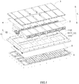
FIG. 1 is an exploded view of a battery pack according to the present invention. -
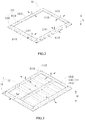
FIG. 2 is a schematic view of a battery pack protective frame according to the present invention. -
FIG. 3 is a schematic view of a lower box body of the battery pack according to the present invention. -
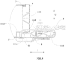
FIG. 4 is a schematic view illustrating a connection between a vehicle fixing member and the battery pack according to the present invention. -
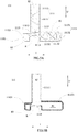
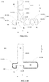
FIG. 5A is a schematic view of a first embodiment of the battery pack protective frame according to the present invention. -
FIG. 5B is a schematic view ofFIG. 5A with all ribbed plates removed. -
FIG. 6A is a schematic view of a second embodiment of the battery pack protective frame according to the present invention. -
FIG. 6B is a schematic view ofFIG. 6A with all ribbed plates removed. -
FIG. 7A is a schematic view of a third embodiment of the battery pack protective frame according to the present invention. -
FIG. 7B is a schematic view ofFIG. 7A with all ribbed plates removed. -
FIG. 8A is a schematic view of a fourth embodiment of the battery pack protective frame according to the present invention. -
FIG. 8B is a schematic view ofFIG. 8A with all ribbed plates removed. -
FIG. 9A is a schematic view of a fifth embodiment of the battery pack protective frame according to the present invention. -
FIG. 9B is a schematic view ofFIG. 9A with all ribbed plates removed. -
FIG. 10A is a schematic view of a sixth embodiment of the battery pack protective frame according to the present invention. -
FIG. 10B is a schematic view ofFIG. 10A with all ribbed plates removed. -
FIG. 11A is a schematic view of a seventh embodiment of the battery pack protective frame according to the present invention. -
FIG. 11B is a schematic view ofFIG. 11A with all ribbed plates removed. -
FIG. 12A is a schematic view of an eighth embodiment of the battery pack protective frame according to the present invention. -
FIG. 12B is a schematic view ofFIG. 12A with all ribbed plates removed. -
FIG. 13A is a schematic view of a ninth embodiment of the battery pack protective frame according to the present invention. -
FIG. 13B is a schematic view ofFIG. 13A with all ribbed plates removed. -
FIG. 14A is a schematic view of a tenth embodiment of the battery pack protective frame according to the present invention. -
FIG. 14B is a schematic view ofFIG. 14A with all ribbed plates removed. -
- 1 lower box body
- 11 battery pack protective frame
- 111 frame component
- 1111 sealing portion
- 11111 sealing portion outer wall
- 11112 sealing portion ribbed plate
- 1112 battery fixed portion
- 11121 battery fixed portion outer wall
- 11122 battery fixed portion ribbed plate
- 1113 protective portion
- 11131 protective portion outer wall
- 11132 protective portion ribbed plate
- 1114 connecting wall
- 1115 inter-portion ribbed plate
- 1111 sealing portion
- 111 frame component
- 12 reinforcing beam
- 11 battery pack protective frame
- 2 battery assembly
- 3 box cover
- 4 gasket
- 5 bottom plate
- 6 protective plate
- S1 protective portion cavity
- S2 sealing portion cavity
- S3 battery fixed portion cavity
- R avoiding recess
- F vehicle fixing member
- U up-down direction
- I inner-outer direction
- Hereinafter a battery pack protective frame and a battery pack according to the present invention will be described in detail in combination with the figures.
- Firstly, a battery pack protective frame according to a first aspect of the present invention will be described.
- Referring to
FIG. 1 to FIG. 14B , a battery packprotective frame 11 according to the present invention comprises a plurality offrame components 111 securely connected together. Eachframe component 111 comprises: a sealingportion 1111 extending in an up-down direction U for sealing a plurality ofbattery assemblies 2 to be mounted; a battery fixedportion 1112 protruding from a lower portion of the sealingportion 1111 toward an inner side in an inner-outer direction I for fixing the plurality ofbattery assemblies 2 to be mounted; and aprotective portion 1113 protruding from the lower portion of the sealingportion 1111 toward an outer side in the inner-outer direction I for connecting with a vehicle fixing member F. - In the battery pack
protective frame 11 according to the present invention, because theprotective portion 1113 is provided on an outer periphery of thecorresponding frame component 111 and is the part bearing the external force firstly when the vehicle collides or is crushed, theprotective portion 1113 may absorb the energy generated in the colliding process or crushing process by generating deformation, thereby effectively protecting thebattery assemblies 2 fixed to the battery fixedportion 1112, preventing thebattery assemblies 2 from colliding or being crushed under the energy impact, avoiding thebattery assemblies 2 firing or exploding. In addition, theprotective portion 1113 is both a protecting structure and a connecting structure between the battery packprotective frame 11 and the vehicle fixing member F, therefore, the battery packprotective frame 11 according to the present invention has high integration and good whole structure property, plays protection function and solves design difficulty problem in the mounting structure between the battery packprotective frame 11 and the vehicle (such as an electric vehicle, the vehicle fixing member F is one component of the vehicle). - In the battery pack
protective frame 11 according to the present invention, a width of theprotective portion 1113 in the inner-outer direction I should be as large as possible on the premise that space is enough, so that theprotective portion 1113 can absorb more energy and improve an anti-crushing ability and an anti-collision ability of the battery packprotective frame 11. - In the battery pack
protective frame 11 according to the present invention, the sealingportion 1111, the battery fixedportion 1112 and theprotective portion 1113 of eachframe component 111 are integrally formed. Preferably, eachframe component 111 is formed by extrusion forming. The plurality offrame components 111 may be securely connected together by welding, thereby forming the battery packprotective frame 11; the plurality offrame components 111 also can be integrally formed to form the battery packprotective frame 11. - In the battery pack
protective frame 11 according to the present invention, the battery fixedportion 1112 is provided with holes fitted with corresponding bolts respectively, so thebattery assemblies 2 can be fixed to the battery fixedportion 1112 by the bolts. Theprotective portion 1113 is provided with holes fitted with corresponding bolts respectively, so theprotective portion 1113 and the vehicle fixing member F are securely connected by the bolts. - In the battery pack
protective frame 11 according to the present invention, eachframe component 111 is made of aluminum alloy. The aluminum alloy can reduce a weight of the battery packprotective frame 11, thereby improving energy density of a battery pack which uses the battery packprotective frame 11 of the present invention. - In the battery pack
protective frame 11 according to the present invention, referring toFIG. 4 to FIG. 14B , theprotective portion 1113 has: a protective portionouter wall 11131 forming an external profile of theprotective portion 1113 and a protective portion cavity S1 inside the protective portionouter wall 11131; and a plurality of protective portion ribbedplates 11132 positioned inside the protective portion cavity S1, supporting the protective portionouter wall 11131 and dividing the protective portion cavity S1 into a plurality of sub-cavities. Theprotective portion 1113 with such a structure can further reduce the weight of theframe component 111 and the plurality of protective portion ribbedplates 11132 also can ensure the whole strength of theprotective portion 1113 at the same time; in addition, when the vehicle collides or is crushed, the stress to which theprotective portion 1113 is subjected will be transmitted along the plurality of protective portion ribbedplates 11132, and in the transmitting process, each protective portion ribbedplate 11132 can absorb energy effectively (each protective portion ribbedplate 11132 will be easily deformed under the stress, so each protective portion ribbedplate 11132 can play function of buffering and absorbing energy), thereby preventing thebattery assemblies 2 from colliding or being crushed under the energy impact. - In the battery pack
protective frame 11 according to the present invention, referring toFIG. 4 ,FIG. 5A ,FIG. 6A ,FIG. 7A ,FIG. 8A ,FIG. 9A ,FIG. 10A ,FIG. 11A ,FIG. 12A ,FIG. 13A andFIG. 14A , each protective portion ribbedplate 11132 is a vertical ribbed plate which is parallel to the up-down direction U, a horizontal ribbed plate which is parallel to the inner-outer direction I, or an oblique ribbed plate which is neither parallel to the up-down direction U nor parallel to the inner-outer direction I. - In the battery pack
protective frame 11 according to the present invention, referring toFIG. 4 ,FIG. 5A ,FIG. 6A ,FIG. 7A ,FIG. 8A ,FIG. 9A ,FIG. 10A ,FIG. 11A ,FIG. 12A andFIG. 13A , two ends of each protective portion ribbedplate 11132 are connected to the protective portionouter wall 11131. - In the battery pack
protective frame 11 according to the present invention, referring toFIG. 8A andFIG. 10A , the two ends of each protective portion ribbedplate 11132 are respectively connected to two opposite parts of the protective portionouter wall 11131 in the up-down direction U. In an embodiment, referring toFIG. 10A , in the plurality of protective portion ribbedplates 11132, there are at least one pair of protective portion ribbedplates 11132 to cross each other. - In the battery pack
protective frame 11 according to the present invention, referring toFIG. 5A andFIG. 13A , in the plurality of protective portion ribbedplates 11132, there are two protective portion ribbedplates 11132 which are provided at an outer end of the protective portion cavity S1 in the inner-outer direction I; in the two protective portion ribbedplates 11132, an end of one protective portion ribbedplate 11132 and an end of the other one protective portion ribbedplate 11132 are connected together and are connected to an outer part of the protective portionouter wall 11131 in the inner-outer direction I, and the other end of the one protective portion ribbedplate 11132 and the other end of the other one protective portion ribbedplate 11132 are respectively connected to two opposite parts of the protective portionouter wall 11131 in the up-down direction U. In an embodiment, referring toFIG. 5A andFIG. 13A , the two protective portion ribbedplates 11132 are symmetric about the inner-outer direction I (the stress can be uniformly transmitted along the two symmetric protective portion ribbed plates 11132). In another embodiment, referring toFIG. 5A andFIG. 13A , in the plurality of protective portion ribbedplates 11132, there is another protective portion ribbedplate 11132 which is further provided in the protective portion cavity S1 of theprotective portion 1113 and connects the other end of the one protective portion ribbedplate 11132 and the other end of the other one protective portion ribbedplate 11132. The another protective portion ribbedplate 11132 and the aforementioned two protective portion ribbedplates 11132 form a triangle, thereby improving the strength of the outer end of theprotective portion 1113 in the inner-outer direction I. - In the battery pack
protective frame 11 according to the present invention, referring toFIG. 5A andFIG. 13A , in the plurality of protective portion ribbedplates 11132, there are two protective portion ribbedplates 11132 which are provided at an inner end of the protective portion cavity S1 in the inner-outer direction I; in the two protective portion ribbedplates 11132, an end of one protective portion ribbedplate 11132 and an end of the other one protective portion ribbedplate 11132 are connected together and are connected to an inner part of the protective portionouter wall 11131 in the inner-outer direction I, and the other end of the one protective portion ribbedplate 11132 and the other end of the other one protective portion ribbedplate 11132 are respectively connected to two opposite parts of the protective portionouter wall 11131 in the up-down direction U. In an embodiment, referring toFIG. 5A andFIG. 13A , the two protective portion ribbedplates 11132 are symmetric about the inner-outer direction I (the stress can be uniformly transmitted along the two symmetric protective portion ribbed plates 11132). In another embodiment, referring toFIG. 5A , in the plurality of protective portion ribbedplates 11132, there is another protective portion ribbedplate 11132 which is further provided in the protective portion cavity S1 of theprotective portion 1113 and connects the other end of the one protective portion ribbedplate 11132 and the other end of the other one protective portion ribbedplate 11132. The another protective portion ribbedplate 11132 and the aforementioned two protective portion ribbedplates 11132 form a triangle, thereby improving the strength of the inner end of theprotective portion 1113 in the inner-outer direction I. - In the battery pack
protective frame 11 according to the present invention, referring toFIG. 6A andFIG. 7A , at least one protective portion ribbedplate 11132 connects two opposite parts of the protective portionouter wall 11131 in the up-down direction U; at least one protective portion ribbedplate 11132 connects two opposite parts of the protective portionouter wall 11131 in the inner-outer direction I; the protective portion ribbedplate 11132 which connects the two opposite parts of the protective portionouter wall 11131 in the up-down direction U and the protective portion ribbedplate 11132 which connects the two opposite parts of the protective portionouter wall 11131 in the inner-outer direction I cross each other. - In the battery pack
protective frame 11 according to the present invention, referring toFIG. 5A ,FIG. 6A ,FIG. 7A ,FIG. 10A ,FIG. 11A ,FIG. 12A ,FIG. 13A andFIG. 14A , in the plurality of protective portion ribbedplates 11132, there are at least one pair of protective portion ribbedplates 11132 to cross each other. - In the battery pack
protective frame 11 according to the present invention, referring toFIG. 4 to FIG. 14B , the sealingportion 1111 has: a sealing portionouter wall 11111 forming an external profile of the sealingportion 1111 and a sealing portion cavity S2 inside the sealing portionouter wall 11111; and a plurality of sealing portion ribbedplates 11112 positioned inside the sealing portion cavity S2, supporting the sealing portionouter wall 11111 and dividing the sealing portion cavity S2 into a plurality of sub-cavities. The sealingportion 1111 with such a structure can further reduce the weight of theframe component 111 and the plurality of sealing portion ribbedplate 11112 also can ensure the whole strength of the sealingportion 1111 at the same time; in addition, when the vehicle collides or is crushed, the sealingportion 1111 will bear bending moment firstly, and each sealing portion ribbedplate 11112 can reduce the influence of the bending moment and absorb energy, thereby further improving the strength of the battery packprotective frame 11 and the protecting ability of the battery packprotective frame 11. - In the battery pack
protective frame 11 according to the present invention, referring toFIG. 4 ,FIG. 5A ,FIG. 6A ,FIG. 7A ,FIG. 8A ,FIG. 9A ,FIG. 10A ,FIG. 11A ,FIG. 12A ,FIG. 13A andFIG. 14A , each sealing portion ribbedplate 11112 is a vertical ribbed plate which is parallel to the up-down direction U, a horizontal ribbed plate which is parallel to the inner-outer direction I, or an oblique ribbed plate which is neither parallel to the up-down direction U nor parallel to the inner-outer direction I. - In the battery pack
protective frame 11 according to the present invention, referring toFIG. 5A ,FIG. 6A ,FIG. 8A ,FIG. 9A ,FIG. 10A ,FIG. 11A ,FIG. 12A ,FIG. 13A andFIG. 14A , two ends of each sealing portion ribbedplate 11112 are connected to the sealing portionouter wall 11111. In an embodiment, referring toFIG. 5A ,FIG. 6A ,FIG. 8A ,FIG. 9A ,FIG. 10A ,FIG. 11A ,FIG. 12A ,FIG. 13A andFIG. 14A , the two ends of each sealing portion ribbedplate 11112 are respectively connected to two opposite parts of the sealing portionouter wall 11111 in the up-down direction U. In another embodiment, referring toFIG. 7A ,FIG. 8A ,FIG. 10A andFIG. 13A , in the plurality of sealing portion ribbedplates 11112, there are at least one pair of sealing portion ribbedplates 11112 to cross each other. - In the battery pack
protective frame 11 according to the present invention, referring toFIG. 5A andFIG. 11A , in the plurality of sealing portion ribbedplates 11112, there is three sealing portion ribbedplates 11112, one of the three sealing portion ribbedplates 11112 is parallel to the inner-outer direction I and the other two of the three sealing portion ribbedplates 11112 are neither parallel to the up-down direction U nor parallel to the inner-outer direction I, and the one of the three sealing portion ribbedplates 11112 is positioned between the other two of the three sealing portion ribbedplates 11112. In an embodiment, referring toFIG. 5A , the other two of the three sealing portion ribbedplates 11112 are symmetric about the one of the three sealing portion ribbedplates 11112. Further, referring toFIG. 5A , the three sealing portion ribbedplates 11112 are positioned in a middle of the sealing portion cavity S2. Because the sealingportion 1111 will bear the bending moment firstly, the three sealing portion ribbedplates 11112 with such an arrangement can improve the bending moment resisting ability of the sealingportion 1111. - In the battery pack
protective frame 11 according to the present invention, referring toFIG. 9A andFIG. 12A , every two adjacent sealing portion ribbedplates 11112 are connected end to end and form a reciprocally folding shape in the up-down direction U. - In the battery pack
protective frame 11 according to the present invention, referring toFIG. 6A andFIG. 14A , each sealing portion ribbedplate 11112 is a horizontal ribbed plate which is parallel to the inner-outer direction I. - In the battery pack
protective frame 11 according to the present invention, referring toFIG. 7A , in the plurality of sealing portion ribbedplates 11112, there is one sealing portion ribbedplate 11112, one end of which is connected to a part of the sealing portionouter wall 11111 in the inner-outer direction I and the other end of which is connected to a part of the sealing portionouter wall 11111 in the up-down direction U. - In the battery pack
protective frame 11 according to the present invention, referring toFIG. 7A , in the plurality of sealing portion ribbedplates 11112, there are three sealing portion ribbedplates 11112, both ends of one of the three sealing portion ribbedplate 11112 are not connected to the sealing portionouter wall 11111 but are respectively connected to the other two of the three sealing portion ribbedplates 11112. - In the battery pack
protective frame 11 according to the present invention, referring toFIG. 4 to FIG. 14B , the battery fixedportion 1112 has a battery fixed portionouter wall 11121 forming an external profile of the battery fixedportion 1112 and a battery fixed portion cavity S3 inside the battery fixed portionouter wall 11121. - In the battery pack
protective frame 11 according to the present invention, referring toFIG. 5A ,FIG. 10A ,FIG. 12A andFIG. 13A , there is no any battery fixed portion ribbedplate 11122 in the battery fixed portion cavity S3. - In the battery pack
protective frame 11 according to the present invention, referring toFIG. 6A ,FIG. 7A ,FIG. 8A ,FIG. 9A ,FIG. 11A andFIG. 14A , the battery fixedportion 1112 further has: at least one battery fixed portion ribbedplate 11122 positioned in the battery fixed portion cavity S3, supporting the battery fixed portionouter wall 11121 and dividing the battery fixed portion cavity S3 into a plurality of sub-cavities. The battery fixed portion ribbedplate 11122 can ensure the strength of the battery fixedportion 1112. - In the battery pack
protective frame 11 according to the present invention, referring toFIG. 6A ,FIG. 7A ,FIG. 8A ,FIG. 9A ,FIG. 11A andFIG. 14A , each battery fixed portion ribbedplate 11122 is a vertical ribbed plate which is parallel to the up-down direction U, a horizontal ribbed plate which is parallel to the inner-outer direction I, or an oblique ribbed plate which is neither parallel to the up-down direction U nor parallel to the inner-outer direction I. - In the battery pack
protective frame 11 according to the present invention, referring toFIG. 6A ,FIG. 7A ,FIG. 8A ,FIG. 9A ,FIG. 11A andFIG. 14A , two ends of each battery fixed portion ribbedplate 11122 are connected to the battery fixed portionouter wall 11121. Furthermore, referring toFIG. 7A , the battery fixed portion ribbedplate 11122 is provided as multiple in number and there are at least one pair of battery fixed portion ribbedplates 11122 to cross each other in the multiple battery fixed portion ribbedplates 11122. - In the battery pack
protective frame 11 according to the present invention, referring toFIG. 5A to FIG. 14B , the sealingportion 1111 has a sealing portionouter wall 11111 forming an external profile of the sealingportion 1111 and a sealing portion cavity S2 inside the sealing portionouter wall 11111; the battery fixedportion 1112 has a battery fixed portionouter wall 11121 forming an external profile of the battery fixedportion 1112 and a battery fixed portion cavity S3 inside the battery fixed portionouter wall 11121, and an end of the battery fixed portionouter wall 11121 is connected to an inner end of the sealing portionouter wall 11111 in the inner-outer direction I. Theprotective portion 1113 has a protective portionouter wall 11131 forming an external profile of theprotective portion 1113 and a protective portion cavity S1 inside the protective portionouter wall 11131, and an end of the protective portionouter wall 11131 is connected to an outer end of the sealing portionouter wall 11111 in the inner-outer direction I. Correspondingly, eachframe component 111 further comprises a connectingwall 1114 connecting the other end of the battery fixed portionouter wall 11121 and the other end of the protective portionouter wall 11131, so that the sealing portionouter wall 11111, the battery fixed portionouter wall 11121, the protective portionouter wall 11131 and the connectingwall 1114 form a closed profile. - In the battery pack
protective frame 11 according to the present invention, referring toFIG. 5A to FIG. 13B , the protective portionouter wall 11131, the battery fixed portionouter wall 11121 and the connectingwall 1114 form an avoiding recess R which is recessed upwardly in the up-down direction U. When the battery packprotective frame 11 acutely collides or is acutely crushed, the battery packprotective frame 11 can be bent in the avoiding recess R, thereby further absorbing energy and better protecting thebattery assemblies 2. - In the battery pack
protective frame 11 according to the present invention, referring toFIG. 5A ,FIG. 6A ,FIG. 8A ,FIG. 10A ,FIG. 11A ,FIG. 12A ,FIG. 13A andFIG. 14A , eachframe component 111 further has at least one inter-portionribbed plate 1115, an end of each inter-portionribbed plate 1115 is connected to the connectingwall 1114, and the other end of the inter-portionribbed plate 1115 is connected to one of the sealing portionouter wall 11111, the battery fixed portionouter wall 11121 and the protective portionouter wall 11131. In an embodiment, referring toFIG. 6A ,FIG. 10A andFIG. 14A , the sealingportion 1111 further has at least one sealing portion ribbedplates 11112 positioned in the sealing portion cavity S2, supporting the sealing portionouter wall 11111 and crossing the inter-portionribbed plate 1115. In another embodiment, referring toFIG. 5A , theprotective portion 1113 further has at least one protective portion ribbedplate 11132 positioned in the protective portion cavity S1 and supporting the protective portionouter wall 11131; one inter-portionribbed plate 1115 and corresponding one protective portion ribbedplate 11132 are located in a straight line and are connected via a joint location between the connectingwall 1114 and the protective portionouter wall 11131. When the battery packprotective frame 11 collides or is crushed, impact force on the corresponding one protective portion ribbedplate 11132 can be transmitted and dispersed along the inter-portionribbed plate 1115, thereby improving the anti-collision ability and the anti-crushing ability of the battery packprotective frame 11. - In the battery pack
protective frame 11 according to the present invention, referring toFIG. 7A , the sealingportion 1111 further has at least one sealing portion ribbedplate 11112 positioned in the sealing portion cavity S2 and supporting the sealing portionouter wall 11111; eachframe component 111 further has at least one inter-portionribbed plate 1115, an end of each inter-portionribbed plate 1115 is connected to the connectingwall 1114 and the other end of each inter-portionribbed plate 1115 is connected to corresponding one sealing portion ribbedplate 11112. - In the battery pack
protective frame 11 according to the present invention, referring toFIG. 6A ,FIG. 7A ,FIG. 8A ,FIG. 9A ,FIG. 11A andFIG. 14A , the sealingportion 1111 further has at least one sealing portion ribbedplate 11112 positioned in the sealing portion cavity S2 and supporting the sealing portionouter wall 11111; the battery fixedportion 1112 further has at least one battery fixed portion ribbedplate 11122 positioned in the battery fixed portion cavity S3 and supporting the battery fixed portionouter wall 11121; theprotective portion 1113 further has at least one protective portion ribbedplate 11132 positioned in the protective portion cavity S1 and supporting the protective portionouter wall 11131. - Secondly, a battery pack according to a second aspect of the present invention will be described.
- Referring to
FIG. 1 to FIG. 14B , a battery pack according to the present invention comprises alower box body 1, a plurality ofbattery assemblies 2, abox cover 3, agasket 4, abottom plate 5 and aprotective plate 6. Thelower box body 1 comprises the battery packprotective frame 11 according to the first aspect of the present invention. The plurality ofbattery assemblies 2 are received in the battery packprotective frame 11 and eachbattery assembly 2 is securely connected to the corresponding battery fixedportion 1112 of theframe component 111. Thebox cover 3 is provided above the battery packprotective frame 11 and securely connected to the sealingportions 1111 of the plurality offrame components 111. Thegasket 4 is interposed between thebox cover 3 and the sealingportions 1111 of the plurality offrame components 111. Thebottom plate 5 is provided under the battery packprotective frame 11 and securely connected to the battery fixedportions 1112 of the plurality offrame components 111. Theprotective plate 6 is provided under thebottom plate 5 and securely connected to theprotective portions 1113 of the plurality offrame components 111. - In the battery pack according to the present invention, because the battery pack
protective frame 11 is connected with the vehicle fixing member F directly, when the vehicle collides or is crushed, theprotective portions 1113 of the battery packprotective frame 11 can absorb the energy generated in the colliding process or crushing process by generating deformation, thereby effectively protecting thebattery assemblies 2 fixed to the battery fixedportion 1112, preventing thebattery assemblies 2 from colliding or being crushed under the energy impact, avoiding thebattery assemblies 2 firing or exploding. In addition, theprotective portion 1113 is both a protecting structure and a connecting structure between the battery packprotective frame 11 and the vehicle fixing member F, therefore, compare to the independent protecting structure and the independent connecting structure of prior art, the protecting structure and the connecting structure of the battery pack of present invention are directly designed as an integral battery packprotective frame 11, which has high integration and improves whole structure performance of the vehicle. - In the battery pack according to the present invention, because each
frame component 111 of the battery packprotective frame 11 may be made of aluminum alloy, and the aluminum alloy can reduce the weight of the battery packprotective frame 11, thereby improving energy density of the battery pack of the present invention. - In the battery pack according to the present invention, each
battery assembly 2 comprises a battery module, voltage control system and current control system. - In the battery pack according to the present invention, the sealing
portion 1111 may be provided with holes, so the sealingportion 1111 can be connected with thebox cover 3 by bolts. In order to ensure a sealing area between the sealingportion 1111 and thebox cover 3, a width of the sealingportion 1111 in inner-outer direction I is not less than 20mm. - In the battery pack according to the present invention, referring to
FIG. 1 andFIG. 3 , thelower box body 1 further comprises a plurality of reinforcingbeams 12 provided inside the battery packprotective frame 11, and two ends of each reinforcingbeam 12 are fixed to corresponding twoframe components 111 respectively. The plurality of reinforcingbeams 12 may be divided into horizontal reinforcing beams and vertical reinforcing beams to cross each other, thereby improving whole strength of thelower box body 1. Each reinforcingbeam 12 may be welded to the sealingportion 1111 or the battery fixedportion 1112 of correspondingframe component 111. - In the battery pack according to the present invention, referring to
FIG. 4 , thebox cover 3 and thebottom plate 5 respectively seal the space surrounded by the battery packprotective frame 11 from two sides in the up-down direction U. Thebottom plate 5 is only used for sealing and does not bear the weight of the battery pack. - In the battery pack according to the present invention, referring to
FIG. 4 , the battery fixedportion 1112 is provided with a notch for welding thebottom plate 5. - In the battery pack according to the present invention, the avoiding recess R formed in the battery pack
protective frame 11 may be used to receive a functional component (such as liquid cooling pipe). - In the battery pack according to the present invention, the
protective plate 6 can protect the battery pack in the working process of the vehicle, avoid gravel impacting, prevent the friction and the collision of the bottom of the vehicle.
Claims (15)
- A battery pack protective frame (11), comprising a plurality of frame components (111) securely connected together, wherein each frame component (111) comprises:a sealing portion (1111) extending in an up-down direction (U) for sealing a plurality of battery assemblies (2) to be mounted;a battery fixed portion (1112) protruding from a lower portion of the sealing portion (1111) toward an inner side in an inner-outer direction (I) for fixing the plurality of battery assemblies (2) to be mounted; anda protective portion (1113) protruding from the lower portion of the sealing portion (1111) toward an outer side in the inner-outer direction (I) for connecting with a vehicle fixing member (F).
- The battery pack protective frame (11) according to Claim 1, wherein the protective portion (1113) has:a protective portion outer wall (11131) forming an external profile of the protective portion (1113) and a protective portion cavity (S1) inside the protective portion outer wall (11131); anda plurality of protective portion ribbed plates (11132) positioned inside the protective portion cavity (S1), supporting the protective portion outer wall (11131) and dividing the protective portion cavity (S1) into a plurality of sub-cavities.
- The battery pack protective frame (11) according to Claim 2, wherein two ends of each protective portion ribbed plate (11132) are connected to the protective portion outer wall (11131).
- The battery pack protective frame (11) according to Claim 3, wherein
in the plurality of protective portion ribbed plates (11132), there are two protective portion ribbed plates (11132) which are provided at an outer end of the protective portion cavity (S1) in the inner-outer direction (I);
in the two protective portion ribbed plates (11132), an end of one protective portion ribbed plate (11132) and an end of the other one protective portion ribbed plate (11132) are connected together and are connected to an outer part of the protective portion outer wall (11131) in the inner-outer direction (I), and the other end of the one protective portion ribbed plate (11132) and the other end of the other one protective portion ribbed plate (11132) are respectively connected to two opposite parts of the protective portion outer wall (11131) in up-down direction (U). - The battery pack protective frame (11) according to Claim 4, wherein in the plurality of protective portion ribbed plates (11132), there is another protective portion ribbed plate (11132) which is further provided in the protective portion cavity (S1) of the protective portion (1113) and connects the other end of the one protective portion ribbed plate (11132) and the other end of the other one protective portion ribbed plate (11132).
- The battery pack protective frame (11) according to Claim 3, wherein
in the plurality of protective portion ribbed plates (11132), there are two protective portion ribbed plates (11132) which are provided at an inner end of the protective portion cavity (S1) in the inner-outer direction (I);
in the two protective portion ribbed plates (11132), an end of one protective portion ribbed plate (11132) and an end of the other one protective portion ribbed plate (11132) are connected together and are connected to an inner part of the protective portion outer wall (11131) in the inner-outer direction (I), and the other end of the one protective portion ribbed plate (11132) and the other end of the other one protective portion ribbed plate (11132) are respectively connected to two opposite parts of the protective portion outer wall (11131) in up-down direction (U). - The battery pack protective frame (11) according to Claim 6, wherein in the plurality of protective portion ribbed plates (11132), there is another protective portion ribbed plate (11132) which is further provided in the protective portion cavity (S1) of the protective portion (1113) and connects the other end of the one protective portion ribbed plate (11132) and the other end of the other one protective portion ribbed plate (11132).
- The battery pack protective frame (11) according to Claim 3, wherein in the plurality of protective portion ribbed plates (11132), there is at least one pair of protective portion ribbed plates (11132) to cross each other.
- The battery pack protective frame (11) according to Claim 1, wherein
the sealing portion (1111) has a sealing portion outer wall (11111) forming an external profile of the sealing portion (1111) and a sealing portion cavity (S2) inside the sealing portion outer wall (11111);
the battery fixed portion (1112) has a battery fixed portion outer wall (11121) forming an external profile of the battery fixed portion (1112) and a battery fixed portion cavity (S3) inside the battery fixed portion outer wall (11121), and an end of the battery fixed portion outer wall (11121) is connected to an inner end of the sealing portion outer wall (11111) in the inner-outer direction (I);
the protective portion (1113) has a protective portion outer wall (11131) forming an external profile of the protective portion (1113) and a protective portion cavity (S1) inside the protective portion outer wall (11131), and an end of the protective portion outer wall (11131) is connected to an outer end of the sealing portion outer wall (11111) in the inner-outer direction (I);
each frame component (111) further comprises a connecting wall (1114) connecting the other end of the battery fixed portion outer wall (11121) and the other end of the protective portion outer wall (11131), so that the sealing portion outer wall (11111), the battery fixed portion outer wall (11121), the protective portion outer wall (11131) and the connecting wall (1114) form a closed profile. - The battery pack protective frame (11) according to Claim 9, wherein the protective portion outer wall (11131), the battery fixed portion outer wall (11121) and the connecting wall (1114) form an avoiding recess (R) which is recessed upwardly in the up-down direction (U).
- The battery pack protective frame (11) according to Claim 9 or Claim 10, wherein each frame component (111) further has at least one inter-portion ribbed plate (1115), an end of each inter-portion ribbed plate (1115) is connected to the connecting wall (1114), and the other end of the corresponding inter-portion ribbed plate (1115) is connected to one of the sealing portion outer wall (11111), the battery fixed portion outer wall (11121) and the protective portion outer wall (11131).
- The battery pack protective frame (11) according to Claim 11, wherein
the protective portion (1113) further has at least one protective portion ribbed plate (11132) positioned in the protective portion cavity (S1) and supporting the protective portion outer wall (11131);
one inter-portion ribbed plate (1115) and corresponding one protective portion ribbed plate (11132) are located in a straight line and are connected via a joint location between the connecting wall (1114) and the protective portion outer wall (11131). - The battery pack protective frame (11) according to Claim 9 or Claim 10, wherein
the sealing portion (1111) further has at least a sealing portion ribbed plate (11112) positioned in the sealing portion cavity (S2) and supporting the sealing portion outer wall (11111);
the battery fixed portion (1112) further has a plurality of battery fixed portion cavity ribbed plates (11122) positioned in the battery fixed portion cavity (S3) and supporting the battery fixed portion outer wall (11121);
the protective portion (1113) further has at least one protective portion ribbed plate (11132) positioned in the protective portion cavity (S1) and supporting the protective portion outer wall (11131). - A battery pack, wherein the battery pack comprises:a lower box body (1) comprising the battery pack protective frame (11) according to any one of Claims 1-13;a plurality of battery assemblies (2) received in the battery pack protective frame (11) and each battery assembly (2) is securely connected to the corresponding battery fixed portion (1112) of the frame component (111);a box cover (3) provided above the battery pack protective frame (11) and securely connected to the sealing portions (1111) of the plurality of frame component (111);a gasket (4) interposed between the box cover (3) and the sealing portions (1111) of the plurality of frame components (111);a bottom plate (5) provided under the battery pack protective frame (11) and securely connected to the battery fixed portions (1112) of the plurality of frame components (111); anda protective plate (6) provided under the bottom plate (5) and securely connected to the protective portions (1113) of the plurality of frame components (111).
- The battery pack according to Claim 14, wherein the lower box body (1) further comprise a plurality of reinforcing beams (12) provided inside the battery pack protective frame (11), and two ends of each reinforcing beam (12) are fixed to corresponding two frame components (111) respectively.
Applications Claiming Priority (1)
| Application Number | Priority Date | Filing Date | Title |
|---|---|---|---|
| CN201710177340.5A CN108630843B (en) | 2017-03-23 | 2017-03-23 | Battery pack protection frame and battery pack |
Publications (2)
| Publication Number | Publication Date |
|---|---|
| EP3379598A1 true EP3379598A1 (en) | 2018-09-26 |
| EP3379598B1 EP3379598B1 (en) | 2020-02-12 |
Family
ID=61655618
Family Applications (1)
| Application Number | Title | Priority Date | Filing Date |
|---|---|---|---|
| EP18161657.4A Active EP3379598B1 (en) | 2017-03-23 | 2018-03-14 | Battery pack protective frame and battery pack |
Country Status (3)
| Country | Link |
|---|---|
| US (1) | US10500936B2 (en) |
| EP (1) | EP3379598B1 (en) |
| CN (1) | CN108630843B (en) |
Cited By (15)
| Publication number | Priority date | Publication date | Assignee | Title |
|---|---|---|---|---|
| CN110137401A (en) * | 2019-04-26 | 2019-08-16 | 浙江新创能源有限公司 | A kind of lithium battery pack |
| US10483510B2 (en) | 2017-05-16 | 2019-11-19 | Shape Corp. | Polarized battery tray for a vehicle |
| US10632857B2 (en) | 2016-08-17 | 2020-04-28 | Shape Corp. | Battery support and protection structure for a vehicle |
| US10661646B2 (en) | 2017-10-04 | 2020-05-26 | Shape Corp. | Battery tray floor assembly for electric vehicles |
| US10886513B2 (en) | 2017-05-16 | 2021-01-05 | Shape Corp. | Vehicle battery tray having tub-based integration |
| US11088412B2 (en) | 2017-09-13 | 2021-08-10 | Shape Corp. | Vehicle battery tray with tubular peripheral wall |
| US11155150B2 (en) | 2018-03-01 | 2021-10-26 | Shape Corp. | Cooling system integrated with vehicle battery tray |
| US11211656B2 (en) | 2017-05-16 | 2021-12-28 | Shape Corp. | Vehicle battery tray with integrated battery retention and support feature |
| US11214137B2 (en) | 2017-01-04 | 2022-01-04 | Shape Corp. | Vehicle battery tray structure with nodal modularity |
| EP3920315A4 (en) * | 2019-11-19 | 2022-06-08 | Contemporary Amperex Technology Co., Limited | BATTERY PACK AND VEHICLE |
| US11688910B2 (en) | 2018-03-15 | 2023-06-27 | Shape Corp. | Vehicle battery tray having tub-based component |
| EP4293806A4 (en) * | 2022-01-05 | 2024-05-29 | Contemporary Amperex Technology Co., Limited | BATTERY, ELECTRICAL DEVICE AND BATTERY MANUFACTURING METHOD |
| CN118596804A (en) * | 2023-08-07 | 2024-09-06 | 华为技术有限公司 | Battery pack box, battery cell integrated body and electric vehicle |
| US12347879B2 (en) | 2017-09-13 | 2025-07-01 | Shape Corp. | Vehicle battery tray with tubular peripheral wall |
| EP4618269A1 (en) * | 2024-03-13 | 2025-09-17 | Eve Energy Co., Ltd. | Battery tray, battery pack, and electrical device |
Families Citing this family (36)
| Publication number | Priority date | Publication date | Assignee | Title |
|---|---|---|---|---|
| JP7020365B2 (en) * | 2018-10-16 | 2022-02-16 | トヨタ自動車株式会社 | In-vehicle battery restraint structure |
| CN111192983B (en) * | 2018-11-15 | 2024-09-10 | 宁德时代新能源科技股份有限公司 | Battery pack |
| CN209176495U (en) | 2018-11-27 | 2019-07-30 | 宁德时代新能源科技股份有限公司 | Battery tray |
| FR3090212B1 (en) * | 2018-12-17 | 2022-01-07 | Valeo Systemes Thermiques | Shock energy absorbing unit for electrical energy storage device |
| CN111599954A (en) * | 2019-02-20 | 2020-08-28 | 广州汽车集团股份有限公司 | Shell structure under battery package and have its new energy automobile |
| DE102019206408A1 (en) | 2019-05-03 | 2020-11-05 | Mahle International Gmbh | Housing part |
| DE102019112105B4 (en) * | 2019-05-09 | 2024-08-08 | Dr. Ing. H.C. F. Porsche Aktiengesellschaft | Electric vehicle with a battery in underfloor arrangement |
| CN210467906U (en) | 2019-07-03 | 2020-05-05 | 江苏时代新能源科技有限公司 | Battery lower box body and battery system |
| JP7344088B2 (en) * | 2019-10-30 | 2023-09-13 | アイシン軽金属株式会社 | Vehicle battery case structure |
| JP7386678B2 (en) * | 2019-11-20 | 2023-11-27 | アイシン軽金属株式会社 | battery protection structure |
| CN210984839U (en) * | 2020-04-24 | 2020-07-10 | 比亚迪股份有限公司 | A battery pack case, battery pack and electric vehicle |
| CN111469681A (en) * | 2020-05-29 | 2020-07-31 | 重庆长安新能源汽车科技有限公司 | A battery pack installation point sealing structure, battery pack and vehicle |
| US12046767B2 (en) * | 2020-07-03 | 2024-07-23 | Teijin Automotive Technologies, Inc. | Battery containment system |
| CN112072025A (en) * | 2020-09-04 | 2020-12-11 | 东风汽车集团有限公司 | Integrated lower bottom plate of anti-extrusion battery lower box and preparation method thereof |
| CN112038525B (en) * | 2020-09-04 | 2022-03-18 | 东风汽车集团有限公司 | Anti-extrusion battery lower case and preparation method thereof |
| CN112248784B (en) * | 2020-10-30 | 2022-01-28 | 上汽通用汽车有限公司 | Battery system connection sealing mechanism, automobile body and automobile |
| JP2022124191A (en) * | 2021-02-15 | 2022-08-25 | 本田技研工業株式会社 | Vehicle body structure |
| WO2022230346A1 (en) * | 2021-04-29 | 2022-11-03 | アイシン軽金属株式会社 | Strength member for in-vehicle battery case, and attachment structure for strength member |
| KR102802530B1 (en) | 2021-06-21 | 2025-04-29 | 주식회사 엘지에너지솔루션 | Battery pack and device including the same |
| US12476314B2 (en) * | 2022-02-17 | 2025-11-18 | GM Global Technology Operations LLC | Structural battery pack |
| KR102639410B1 (en) * | 2022-05-16 | 2024-02-22 | 주식회사 엘지에너지솔루션 | Battery pack |
| WO2024005392A1 (en) * | 2022-06-27 | 2024-01-04 | 주식회사 엘지에너지솔루션 | Battery pack |
| CN115020898B (en) * | 2022-08-09 | 2022-11-04 | 楚能新能源股份有限公司 | Battery box |
| WO2024058577A1 (en) * | 2022-09-16 | 2024-03-21 | 주식회사 엘지에너지솔루션 | Battery pack case and battery pack comprising same |
| WO2024082200A1 (en) * | 2022-10-20 | 2024-04-25 | 宁德时代新能源科技股份有限公司 | Protection board, and vehicle |
| KR102963876B1 (en) * | 2022-11-23 | 2026-05-11 | 주식회사 엘지에너지솔루션 | Battery pack and device including the same |
| CN119601865B (en) * | 2023-09-08 | 2026-06-19 | 宁德时代新能源科技股份有限公司 | Box, battery and electric equipment |
| KR102716613B1 (en) * | 2023-11-02 | 2024-10-16 | 덕양산업 주식회사 | Battery pack with improved energy density and enhanced rigidity |
| KR20250064227A (en) | 2023-11-02 | 2025-05-09 | 주식회사 엘지에너지솔루션 | Pack housing |
| KR102754965B1 (en) * | 2023-11-02 | 2025-01-22 | 덕양산업 주식회사 | Battery pack with blocked airtight structure and enhanced rigidity |
| GB2638669A (en) * | 2024-02-21 | 2025-09-03 | Jaguar Land Rover Ltd | Impact protector for mounting to a vehicle battery assembly of an offroad-capable vehicle |
| FR3159931A1 (en) | 2024-03-08 | 2025-09-12 | Qinomic | Chassis for motor vehicle traction battery pack with extruded structural section |
| JP2026010814A (en) * | 2024-07-10 | 2026-01-23 | 本田技研工業株式会社 | Battery storage case |
| CN122139265A (en) * | 2024-07-31 | 2026-06-02 | 宁德时代新能源科技股份有限公司 | Battery devices and electrical appliances |
| CN119297497A (en) * | 2024-09-13 | 2025-01-10 | 惠州亿纬锂能股份有限公司 | Beam structure, battery box and battery pack |
| WO2026126476A1 (en) * | 2024-12-13 | 2026-06-18 | 三菱自動車工業株式会社 | Vehicle-width-direction end portion structure of battery pack |
Citations (5)
| Publication number | Priority date | Publication date | Assignee | Title |
|---|---|---|---|---|
| US20130088044A1 (en) * | 2010-12-22 | 2013-04-11 | Tesla Motors, Inc. | System for Absorbing and Distributing Side Impact Energy Utilizing an Integrated Battery Pack and Side Sill Assembly |
| US20150021939A1 (en) * | 2013-07-22 | 2015-01-22 | GM Global Technology Operations LLC | Energy absorbing vehicle component |
| US20160257346A1 (en) * | 2015-03-05 | 2016-09-08 | Ford Global Technologies, Llc | Energy absorbing rocker assembly |
| US20160311301A1 (en) * | 2013-12-25 | 2016-10-27 | Toyota Jidosha Kabushiki Kaisha | Vehicle battery mounting structure |
| US20170001507A1 (en) * | 2015-06-30 | 2017-01-05 | Faraday&Future Inc. | Underbody for a Motor Vehicle |
Family Cites Families (10)
| Publication number | Priority date | Publication date | Assignee | Title |
|---|---|---|---|---|
| KR101174045B1 (en) * | 2010-09-29 | 2012-08-16 | 주식회사 명신이엔지 | Battery pack and battery pack assembly having the same |
| JP5575035B2 (en) | 2011-03-29 | 2014-08-20 | 株式会社神戸製鋼所 | Car battery frame structure |
| CN202977558U (en) | 2012-11-27 | 2013-06-05 | 广东精进能源有限公司 | Impact resisting structure of power battery pack |
| JP2013152935A (en) * | 2013-02-28 | 2013-08-08 | Lg Chem Ltd | Large capacity battery pack |
| CN103367670B (en) | 2013-07-10 | 2015-07-15 | 湖北浩天朗能新能源科技有限公司 | Lightweight battery box body for electric automobile and manufacture method thereof |
| CN103337601B (en) | 2013-07-10 | 2016-01-20 | 湖北浩天朗能新能源科技有限公司 | The Battery case of electric automobile and manufacture method thereof |
| JP6337603B2 (en) * | 2014-05-13 | 2018-06-06 | 三菱自動車工業株式会社 | Battery pack |
| CN104617244B (en) | 2014-12-05 | 2017-02-22 | 超威电源有限公司 | Electric-car storage-battery anti-shock crashproof structure |
| CN205202706U (en) | 2015-12-01 | 2016-05-04 | 上海汽车集团股份有限公司 | Electricelectric motor car power battery frame construction |
| CN205871713U (en) * | 2016-08-11 | 2017-01-11 | 宁德时代新能源科技股份有限公司 | Battery package is box down |
-
2017
- 2017-03-23 CN CN201710177340.5A patent/CN108630843B/en active Active
-
2018
- 2018-03-07 US US15/914,775 patent/US10500936B2/en active Active
- 2018-03-14 EP EP18161657.4A patent/EP3379598B1/en active Active
Patent Citations (5)
| Publication number | Priority date | Publication date | Assignee | Title |
|---|---|---|---|---|
| US20130088044A1 (en) * | 2010-12-22 | 2013-04-11 | Tesla Motors, Inc. | System for Absorbing and Distributing Side Impact Energy Utilizing an Integrated Battery Pack and Side Sill Assembly |
| US20150021939A1 (en) * | 2013-07-22 | 2015-01-22 | GM Global Technology Operations LLC | Energy absorbing vehicle component |
| US20160311301A1 (en) * | 2013-12-25 | 2016-10-27 | Toyota Jidosha Kabushiki Kaisha | Vehicle battery mounting structure |
| US20160257346A1 (en) * | 2015-03-05 | 2016-09-08 | Ford Global Technologies, Llc | Energy absorbing rocker assembly |
| US20170001507A1 (en) * | 2015-06-30 | 2017-01-05 | Faraday&Future Inc. | Underbody for a Motor Vehicle |
Cited By (23)
| Publication number | Priority date | Publication date | Assignee | Title |
|---|---|---|---|---|
| US11273697B2 (en) | 2016-08-17 | 2022-03-15 | Shape Corp. | Battery support and protection structure for a vehicle |
| US10632857B2 (en) | 2016-08-17 | 2020-04-28 | Shape Corp. | Battery support and protection structure for a vehicle |
| US11660950B2 (en) | 2016-08-17 | 2023-05-30 | Shape Corp. | Battery support and protection structure for a vehicle |
| US11214137B2 (en) | 2017-01-04 | 2022-01-04 | Shape Corp. | Vehicle battery tray structure with nodal modularity |
| US10483510B2 (en) | 2017-05-16 | 2019-11-19 | Shape Corp. | Polarized battery tray for a vehicle |
| US10886513B2 (en) | 2017-05-16 | 2021-01-05 | Shape Corp. | Vehicle battery tray having tub-based integration |
| US11691493B2 (en) | 2017-05-16 | 2023-07-04 | Shape Corp. | Vehicle battery tray having tub-based component |
| US11211656B2 (en) | 2017-05-16 | 2021-12-28 | Shape Corp. | Vehicle battery tray with integrated battery retention and support feature |
| US12347879B2 (en) | 2017-09-13 | 2025-07-01 | Shape Corp. | Vehicle battery tray with tubular peripheral wall |
| US11088412B2 (en) | 2017-09-13 | 2021-08-10 | Shape Corp. | Vehicle battery tray with tubular peripheral wall |
| US10960748B2 (en) | 2017-10-04 | 2021-03-30 | Shape Corp. | Battery tray floor assembly for electric vehicles |
| US11267327B2 (en) | 2017-10-04 | 2022-03-08 | Shape Corp. | Battery tray floor assembly for electric vehicles |
| US11787278B2 (en) | 2017-10-04 | 2023-10-17 | Shape Corp. | Battery tray floor assembly for electric vehicles |
| US10661646B2 (en) | 2017-10-04 | 2020-05-26 | Shape Corp. | Battery tray floor assembly for electric vehicles |
| US11155150B2 (en) | 2018-03-01 | 2021-10-26 | Shape Corp. | Cooling system integrated with vehicle battery tray |
| US11688910B2 (en) | 2018-03-15 | 2023-06-27 | Shape Corp. | Vehicle battery tray having tub-based component |
| CN110137401A (en) * | 2019-04-26 | 2019-08-16 | 浙江新创能源有限公司 | A kind of lithium battery pack |
| EP3920315A4 (en) * | 2019-11-19 | 2022-06-08 | Contemporary Amperex Technology Co., Limited | BATTERY PACK AND VEHICLE |
| US12054039B2 (en) | 2019-11-19 | 2024-08-06 | Contemporary Amperex Technology Co., Limited | Battery pack and vehicle |
| EP4293806A4 (en) * | 2022-01-05 | 2024-05-29 | Contemporary Amperex Technology Co., Limited | BATTERY, ELECTRICAL DEVICE AND BATTERY MANUFACTURING METHOD |
| CN118596804A (en) * | 2023-08-07 | 2024-09-06 | 华为技术有限公司 | Battery pack box, battery cell integrated body and electric vehicle |
| EP4618269A1 (en) * | 2024-03-13 | 2025-09-17 | Eve Energy Co., Ltd. | Battery tray, battery pack, and electrical device |
| JP2025141760A (en) * | 2024-03-13 | 2025-09-29 | 恵州億緯▲リ▼能股▲フン▼有限公司 | Battery tray, battery pack, and electrical facility |
Also Published As
| Publication number | Publication date |
|---|---|
| EP3379598B1 (en) | 2020-02-12 |
| CN108630843A (en) | 2018-10-09 |
| US20180272853A1 (en) | 2018-09-27 |
| US10500936B2 (en) | 2019-12-10 |
| CN108630843B (en) | 2023-10-24 |
Similar Documents
| Publication | Publication Date | Title |
|---|---|---|
| US10500936B2 (en) | Battery pack protective frame and battery pack | |
| KR102488495B1 (en) | Battery case | |
| CN206584986U (en) | Battery bag shielded frame and battery bag | |
| US10938007B2 (en) | Battery housing and motor vehicle comprising a battery housing of this kind | |
| CN109941083B (en) | Battery pack protection structure for vehicle and vehicle provided with same | |
| EP2896551A1 (en) | Vehicle body front structure | |
| JP2018202897A (en) | Bumper beam structure | |
| CN206584985U (en) | Battery bag shielded frame and battery bag | |
| CN206584984U (en) | Battery bag shielded frame and battery bag | |
| JP2022097814A (en) | Fastening structure for vehicular battery pack | |
| JP2023075430A (en) | Side sill internal structure | |
| JP2017185948A (en) | Vehicle battery mounting structure | |
| CN108162900B (en) | Bumper assembly for a motor vehicle | |
| JP7563664B1 (en) | Battery case | |
| JP2015107701A (en) | Vehicle hood structure | |
| CN206584967U (en) | Battery bag shielded frame and battery bag | |
| CN110789479A (en) | Front-end anti-collision device of vehicle body | |
| CN209880686U (en) | Battery box and battery box body | |
| KR102922368B1 (en) | Battery case for vehicle | |
| CN212022569U (en) | Energy absorption box and car | |
| US11981370B2 (en) | Structural member for vehicle | |
| CN210793365U (en) | New energy automobile and threshold structure thereof | |
| CN217672514U (en) | Front anti-collision beam and automobile | |
| CN204077819U (en) | The left longeron of machinery space and machinery space front wall assembly | |
| CN207403689U (en) | A new type of energy-absorbing box assembly and automobile |
Legal Events
| Date | Code | Title | Description |
|---|---|---|---|
| PUAI | Public reference made under article 153(3) epc to a published international application that has entered the european phase |
Free format text: ORIGINAL CODE: 0009012 |
|
| STAA | Information on the status of an ep patent application or granted ep patent |
Free format text: STATUS: REQUEST FOR EXAMINATION WAS MADE |
|
| 17P | Request for examination filed |
Effective date: 20180314 |
|
| AK | Designated contracting states |
Kind code of ref document: A1 Designated state(s): AL AT BE BG CH CY CZ DE DK EE ES FI FR GB GR HR HU IE IS IT LI LT LU LV MC MK MT NL NO PL PT RO RS SE SI SK SM TR |
|
| AX | Request for extension of the european patent |
Extension state: BA ME |
|
| GRAP | Despatch of communication of intention to grant a patent |
Free format text: ORIGINAL CODE: EPIDOSNIGR1 |
|
| RIC1 | Information provided on ipc code assigned before grant |
Ipc: B60K 1/04 20190101ALI20190715BHEP Ipc: H01M 2/10 20060101AFI20190715BHEP Ipc: B60L 50/60 20190101ALI20190715BHEP Ipc: H01M 2/02 20060101ALI20190715BHEP Ipc: B60L 50/64 20190101ALI20190715BHEP Ipc: B60L 3/00 20190101ALI20190715BHEP |
|
| STAA | Information on the status of an ep patent application or granted ep patent |
Free format text: STATUS: GRANT OF PATENT IS INTENDED |
|
| INTG | Intention to grant announced |
Effective date: 20190822 |
|
| GRAS | Grant fee paid |
Free format text: ORIGINAL CODE: EPIDOSNIGR3 |
|
| GRAA | (expected) grant |
Free format text: ORIGINAL CODE: 0009210 |
|
| STAA | Information on the status of an ep patent application or granted ep patent |
Free format text: STATUS: THE PATENT HAS BEEN GRANTED |
|
| AK | Designated contracting states |
Kind code of ref document: B1 Designated state(s): AL AT BE BG CH CY CZ DE DK EE ES FI FR GB GR HR HU IE IS IT LI LT LU LV MC MK MT NL NO PL PT RO RS SE SI SK SM TR |
|
| REG | Reference to a national code |
Ref country code: GB Ref legal event code: FG4D |
|
| REG | Reference to a national code |
Ref country code: CH Ref legal event code: EP |
|
| REG | Reference to a national code |
Ref country code: AT Ref legal event code: REF Ref document number: 1233282 Country of ref document: AT Kind code of ref document: T Effective date: 20200215 |
|
| REG | Reference to a national code |
Ref country code: IE Ref legal event code: FG4D |
|
| REG | Reference to a national code |
Ref country code: DE Ref legal event code: R096 Ref document number: 602018002321 Country of ref document: DE |
|
| PG25 | Lapsed in a contracting state [announced via postgrant information from national office to epo] |
Ref country code: FI Free format text: LAPSE BECAUSE OF FAILURE TO SUBMIT A TRANSLATION OF THE DESCRIPTION OR TO PAY THE FEE WITHIN THE PRESCRIBED TIME-LIMIT Effective date: 20200212 Ref country code: RS Free format text: LAPSE BECAUSE OF FAILURE TO SUBMIT A TRANSLATION OF THE DESCRIPTION OR TO PAY THE FEE WITHIN THE PRESCRIBED TIME-LIMIT Effective date: 20200212 Ref country code: NO Free format text: LAPSE BECAUSE OF FAILURE TO SUBMIT A TRANSLATION OF THE DESCRIPTION OR TO PAY THE FEE WITHIN THE PRESCRIBED TIME-LIMIT Effective date: 20200512 |
|
| REG | Reference to a national code |
Ref country code: LT Ref legal event code: MG4D |
|
| REG | Reference to a national code |
Ref country code: NL Ref legal event code: MP Effective date: 20200212 |
|
| PG25 | Lapsed in a contracting state [announced via postgrant information from national office to epo] |
Ref country code: BG Free format text: LAPSE BECAUSE OF FAILURE TO SUBMIT A TRANSLATION OF THE DESCRIPTION OR TO PAY THE FEE WITHIN THE PRESCRIBED TIME-LIMIT Effective date: 20200512 Ref country code: HR Free format text: LAPSE BECAUSE OF FAILURE TO SUBMIT A TRANSLATION OF THE DESCRIPTION OR TO PAY THE FEE WITHIN THE PRESCRIBED TIME-LIMIT Effective date: 20200212 Ref country code: IS Free format text: LAPSE BECAUSE OF FAILURE TO SUBMIT A TRANSLATION OF THE DESCRIPTION OR TO PAY THE FEE WITHIN THE PRESCRIBED TIME-LIMIT Effective date: 20200612 Ref country code: SE Free format text: LAPSE BECAUSE OF FAILURE TO SUBMIT A TRANSLATION OF THE DESCRIPTION OR TO PAY THE FEE WITHIN THE PRESCRIBED TIME-LIMIT Effective date: 20200212 Ref country code: GR Free format text: LAPSE BECAUSE OF FAILURE TO SUBMIT A TRANSLATION OF THE DESCRIPTION OR TO PAY THE FEE WITHIN THE PRESCRIBED TIME-LIMIT Effective date: 20200513 Ref country code: LV Free format text: LAPSE BECAUSE OF FAILURE TO SUBMIT A TRANSLATION OF THE DESCRIPTION OR TO PAY THE FEE WITHIN THE PRESCRIBED TIME-LIMIT Effective date: 20200212 |
|
| PG25 | Lapsed in a contracting state [announced via postgrant information from national office to epo] |
Ref country code: NL Free format text: LAPSE BECAUSE OF FAILURE TO SUBMIT A TRANSLATION OF THE DESCRIPTION OR TO PAY THE FEE WITHIN THE PRESCRIBED TIME-LIMIT Effective date: 20200212 |
|
| PG25 | Lapsed in a contracting state [announced via postgrant information from national office to epo] |
Ref country code: LT Free format text: LAPSE BECAUSE OF FAILURE TO SUBMIT A TRANSLATION OF THE DESCRIPTION OR TO PAY THE FEE WITHIN THE PRESCRIBED TIME-LIMIT Effective date: 20200212 Ref country code: EE Free format text: LAPSE BECAUSE OF FAILURE TO SUBMIT A TRANSLATION OF THE DESCRIPTION OR TO PAY THE FEE WITHIN THE PRESCRIBED TIME-LIMIT Effective date: 20200212 Ref country code: SM Free format text: LAPSE BECAUSE OF FAILURE TO SUBMIT A TRANSLATION OF THE DESCRIPTION OR TO PAY THE FEE WITHIN THE PRESCRIBED TIME-LIMIT Effective date: 20200212 Ref country code: DK Free format text: LAPSE BECAUSE OF FAILURE TO SUBMIT A TRANSLATION OF THE DESCRIPTION OR TO PAY THE FEE WITHIN THE PRESCRIBED TIME-LIMIT Effective date: 20200212 Ref country code: CZ Free format text: LAPSE BECAUSE OF FAILURE TO SUBMIT A TRANSLATION OF THE DESCRIPTION OR TO PAY THE FEE WITHIN THE PRESCRIBED TIME-LIMIT Effective date: 20200212 Ref country code: RO Free format text: LAPSE BECAUSE OF FAILURE TO SUBMIT A TRANSLATION OF THE DESCRIPTION OR TO PAY THE FEE WITHIN THE PRESCRIBED TIME-LIMIT Effective date: 20200212 Ref country code: SK Free format text: LAPSE BECAUSE OF FAILURE TO SUBMIT A TRANSLATION OF THE DESCRIPTION OR TO PAY THE FEE WITHIN THE PRESCRIBED TIME-LIMIT Effective date: 20200212 Ref country code: ES Free format text: LAPSE BECAUSE OF FAILURE TO SUBMIT A TRANSLATION OF THE DESCRIPTION OR TO PAY THE FEE WITHIN THE PRESCRIBED TIME-LIMIT Effective date: 20200212 Ref country code: PT Free format text: LAPSE BECAUSE OF FAILURE TO SUBMIT A TRANSLATION OF THE DESCRIPTION OR TO PAY THE FEE WITHIN THE PRESCRIBED TIME-LIMIT Effective date: 20200705 |
|
| REG | Reference to a national code |
Ref country code: DE Ref legal event code: R097 Ref document number: 602018002321 Country of ref document: DE |
|
| REG | Reference to a national code |
Ref country code: AT Ref legal event code: MK05 Ref document number: 1233282 Country of ref document: AT Kind code of ref document: T Effective date: 20200212 |
|
| REG | Reference to a national code |
Ref country code: DE Ref legal event code: R079 Ref document number: 602018002321 Country of ref document: DE Free format text: PREVIOUS MAIN CLASS: H01M0002100000 Ipc: H01M0050200000 |
|
| PG25 | Lapsed in a contracting state [announced via postgrant information from national office to epo] |
Ref country code: MC Free format text: LAPSE BECAUSE OF FAILURE TO SUBMIT A TRANSLATION OF THE DESCRIPTION OR TO PAY THE FEE WITHIN THE PRESCRIBED TIME-LIMIT Effective date: 20200212 |
|
| PLBE | No opposition filed within time limit |
Free format text: ORIGINAL CODE: 0009261 |
|
| STAA | Information on the status of an ep patent application or granted ep patent |
Free format text: STATUS: NO OPPOSITION FILED WITHIN TIME LIMIT |
|
| REG | Reference to a national code |
Ref country code: BE Ref legal event code: MM Effective date: 20200331 |
|
| PG25 | Lapsed in a contracting state [announced via postgrant information from national office to epo] |
Ref country code: LU Free format text: LAPSE BECAUSE OF NON-PAYMENT OF DUE FEES Effective date: 20200314 |
|
| 26N | No opposition filed |
Effective date: 20201113 |
|
| PG25 | Lapsed in a contracting state [announced via postgrant information from national office to epo] |
Ref country code: AT Free format text: LAPSE BECAUSE OF FAILURE TO SUBMIT A TRANSLATION OF THE DESCRIPTION OR TO PAY THE FEE WITHIN THE PRESCRIBED TIME-LIMIT Effective date: 20200212 Ref country code: IT Free format text: LAPSE BECAUSE OF FAILURE TO SUBMIT A TRANSLATION OF THE DESCRIPTION OR TO PAY THE FEE WITHIN THE PRESCRIBED TIME-LIMIT Effective date: 20200212 Ref country code: IE Free format text: LAPSE BECAUSE OF NON-PAYMENT OF DUE FEES Effective date: 20200314 |
|
| PG25 | Lapsed in a contracting state [announced via postgrant information from national office to epo] |
Ref country code: SI Free format text: LAPSE BECAUSE OF FAILURE TO SUBMIT A TRANSLATION OF THE DESCRIPTION OR TO PAY THE FEE WITHIN THE PRESCRIBED TIME-LIMIT Effective date: 20200212 Ref country code: PL Free format text: LAPSE BECAUSE OF FAILURE TO SUBMIT A TRANSLATION OF THE DESCRIPTION OR TO PAY THE FEE WITHIN THE PRESCRIBED TIME-LIMIT Effective date: 20200212 Ref country code: BE Free format text: LAPSE BECAUSE OF NON-PAYMENT OF DUE FEES Effective date: 20200331 |
|
| REG | Reference to a national code |
Ref country code: CH Ref legal event code: PL |
|
| PG25 | Lapsed in a contracting state [announced via postgrant information from national office to epo] |
Ref country code: LI Free format text: LAPSE BECAUSE OF NON-PAYMENT OF DUE FEES Effective date: 20210331 Ref country code: CH Free format text: LAPSE BECAUSE OF NON-PAYMENT OF DUE FEES Effective date: 20210331 |
|
| PG25 | Lapsed in a contracting state [announced via postgrant information from national office to epo] |
Ref country code: TR Free format text: LAPSE BECAUSE OF FAILURE TO SUBMIT A TRANSLATION OF THE DESCRIPTION OR TO PAY THE FEE WITHIN THE PRESCRIBED TIME-LIMIT Effective date: 20200212 Ref country code: MT Free format text: LAPSE BECAUSE OF FAILURE TO SUBMIT A TRANSLATION OF THE DESCRIPTION OR TO PAY THE FEE WITHIN THE PRESCRIBED TIME-LIMIT Effective date: 20200212 Ref country code: CY Free format text: LAPSE BECAUSE OF FAILURE TO SUBMIT A TRANSLATION OF THE DESCRIPTION OR TO PAY THE FEE WITHIN THE PRESCRIBED TIME-LIMIT Effective date: 20200212 |
|
| PG25 | Lapsed in a contracting state [announced via postgrant information from national office to epo] |
Ref country code: MK Free format text: LAPSE BECAUSE OF FAILURE TO SUBMIT A TRANSLATION OF THE DESCRIPTION OR TO PAY THE FEE WITHIN THE PRESCRIBED TIME-LIMIT Effective date: 20200212 Ref country code: AL Free format text: LAPSE BECAUSE OF FAILURE TO SUBMIT A TRANSLATION OF THE DESCRIPTION OR TO PAY THE FEE WITHIN THE PRESCRIBED TIME-LIMIT Effective date: 20200212 |
|
| P01 | Opt-out of the competence of the unified patent court (upc) registered |
Effective date: 20230516 |
|
| REG | Reference to a national code |
Ref country code: DE Ref legal event code: R082 Ref document number: 602018002321 Country of ref document: DE Ref country code: DE Ref legal event code: R081 Ref document number: 602018002321 Country of ref document: DE Owner name: CONTEMPORARY AMPEREX TECHNOLOGY (HONG KONG) LI, HK Free format text: FORMER OWNER: CONTEMPORARY AMPEREX TECHNOLOGY CO., LTD., NINGDE CITY, FUJIAN, CN |
|
| REG | Reference to a national code |
Ref country code: GB Ref legal event code: 732E Free format text: REGISTERED BETWEEN 20240815 AND 20240821 |
|
| PGFP | Annual fee paid to national office [announced via postgrant information from national office to epo] |
Ref country code: FR Payment date: 20251231 Year of fee payment: 9 |
|
| PGFP | Annual fee paid to national office [announced via postgrant information from national office to epo] |
Ref country code: GB Payment date: 20260106 Year of fee payment: 9 |
|
| PGFP | Annual fee paid to national office [announced via postgrant information from national office to epo] |
Ref country code: DE Payment date: 20260102 Year of fee payment: 9 |