EP3379455A1 - Ledger document processing device, ledger document processing method and storage medium - Google Patents
Ledger document processing device, ledger document processing method and storage medium Download PDFInfo
- Publication number
- EP3379455A1 EP3379455A1 EP18158251.1A EP18158251A EP3379455A1 EP 3379455 A1 EP3379455 A1 EP 3379455A1 EP 18158251 A EP18158251 A EP 18158251A EP 3379455 A1 EP3379455 A1 EP 3379455A1
- Authority
- EP
- European Patent Office
- Prior art keywords
- slip
- image
- captured
- size
- ledger document
- Prior art date
- Legal status (The legal status is an assumption and is not a legal conclusion. Google has not performed a legal analysis and makes no representation as to the accuracy of the status listed.)
- Granted
Links
Images







Classifications
-
- G—PHYSICS
- G06—COMPUTING OR CALCULATING; COUNTING
- G06K—GRAPHICAL DATA READING; PRESENTATION OF DATA; RECORD CARRIERS; HANDLING RECORD CARRIERS
- G06K7/00—Methods or arrangements for sensing record carriers, e.g. for reading patterns
- G06K7/10—Methods or arrangements for sensing record carriers, e.g. for reading patterns by electromagnetic radiation, e.g. optical sensing; by corpuscular radiation
- G06K7/10544—Methods or arrangements for sensing record carriers, e.g. for reading patterns by electromagnetic radiation, e.g. optical sensing; by corpuscular radiation by scanning of the records by radiation in the optical part of the electromagnetic spectrum
- G06K7/10712—Fixed beam scanning
- G06K7/10722—Photodetector array or CCD scanning
-
- G—PHYSICS
- G06—COMPUTING OR CALCULATING; COUNTING
- G06V—IMAGE OR VIDEO RECOGNITION OR UNDERSTANDING
- G06V30/00—Character recognition; Recognising digital ink; Document-oriented image-based pattern recognition
- G06V30/40—Document-oriented image-based pattern recognition
- G06V30/41—Analysis of document content
- G06V30/412—Layout analysis of documents structured with printed lines or input boxes, e.g. business forms or tables
-
- G—PHYSICS
- G06—COMPUTING OR CALCULATING; COUNTING
- G06K—GRAPHICAL DATA READING; PRESENTATION OF DATA; RECORD CARRIERS; HANDLING RECORD CARRIERS
- G06K7/00—Methods or arrangements for sensing record carriers, e.g. for reading patterns
- G06K7/01—Details
- G06K7/015—Aligning or centering of the sensing device with respect to the record carrier
-
- G—PHYSICS
- G06—COMPUTING OR CALCULATING; COUNTING
- G06K—GRAPHICAL DATA READING; PRESENTATION OF DATA; RECORD CARRIERS; HANDLING RECORD CARRIERS
- G06K7/00—Methods or arrangements for sensing record carriers, e.g. for reading patterns
- G06K7/10—Methods or arrangements for sensing record carriers, e.g. for reading patterns by electromagnetic radiation, e.g. optical sensing; by corpuscular radiation
- G06K7/14—Methods or arrangements for sensing record carriers, e.g. for reading patterns by electromagnetic radiation, e.g. optical sensing; by corpuscular radiation using light without selection of wavelength, e.g. sensing reflected white light
- G06K7/1404—Methods for optical code recognition
- G06K7/1408—Methods for optical code recognition the method being specifically adapted for the type of code
- G06K7/1413—1D bar codes
-
- G—PHYSICS
- G06—COMPUTING OR CALCULATING; COUNTING
- G06K—GRAPHICAL DATA READING; PRESENTATION OF DATA; RECORD CARRIERS; HANDLING RECORD CARRIERS
- G06K7/00—Methods or arrangements for sensing record carriers, e.g. for reading patterns
- G06K7/10—Methods or arrangements for sensing record carriers, e.g. for reading patterns by electromagnetic radiation, e.g. optical sensing; by corpuscular radiation
- G06K7/14—Methods or arrangements for sensing record carriers, e.g. for reading patterns by electromagnetic radiation, e.g. optical sensing; by corpuscular radiation using light without selection of wavelength, e.g. sensing reflected white light
- G06K7/1404—Methods for optical code recognition
- G06K7/1439—Methods for optical code recognition including a method step for retrieval of the optical code
- G06K7/1447—Methods for optical code recognition including a method step for retrieval of the optical code extracting optical codes from image or text carrying said optical code
-
- G—PHYSICS
- G06—COMPUTING OR CALCULATING; COUNTING
- G06V—IMAGE OR VIDEO RECOGNITION OR UNDERSTANDING
- G06V10/00—Arrangements for image or video recognition or understanding
- G06V10/20—Image preprocessing
- G06V10/22—Image preprocessing by selection of a specific region containing or referencing a pattern; Locating or processing of specific regions to guide the detection or recognition
- G06V10/235—Image preprocessing by selection of a specific region containing or referencing a pattern; Locating or processing of specific regions to guide the detection or recognition based on user input or interaction
-
- G—PHYSICS
- G06—COMPUTING OR CALCULATING; COUNTING
- G06V—IMAGE OR VIDEO RECOGNITION OR UNDERSTANDING
- G06V30/00—Character recognition; Recognising digital ink; Document-oriented image-based pattern recognition
- G06V30/10—Character recognition
- G06V30/22—Character recognition characterised by the type of writing
- G06V30/224—Character recognition characterised by the type of writing of printed characters having additional code marks or containing code marks
- G06V30/2247—Characters composed of bars, e.g. CMC-7
-
- G—PHYSICS
- G06—COMPUTING OR CALCULATING; COUNTING
- G06V—IMAGE OR VIDEO RECOGNITION OR UNDERSTANDING
- G06V30/00—Character recognition; Recognising digital ink; Document-oriented image-based pattern recognition
- G06V30/40—Document-oriented image-based pattern recognition
- G06V30/41—Analysis of document content
- G06V30/414—Extracting the geometrical structure, e.g. layout tree; Block segmentation, e.g. bounding boxes for graphics or text
-
- H—ELECTRICITY
- H04—ELECTRIC COMMUNICATION TECHNIQUE
- H04N—PICTORIAL COMMUNICATION, e.g. TELEVISION
- H04N23/00—Cameras or camera modules comprising electronic image sensors; Control thereof
- H04N23/60—Control of cameras or camera modules
- H04N23/63—Control of cameras or camera modules by using electronic viewfinders
-
- H—ELECTRICITY
- H04—ELECTRIC COMMUNICATION TECHNIQUE
- H04N—PICTORIAL COMMUNICATION, e.g. TELEVISION
- H04N23/00—Cameras or camera modules comprising electronic image sensors; Control thereof
- H04N23/60—Control of cameras or camera modules
- H04N23/64—Computer-aided capture of images, e.g. transfer from script file into camera, check of taken image quality, advice or proposal for image composition or decision on when to take image
-
- H—ELECTRICITY
- H04—ELECTRIC COMMUNICATION TECHNIQUE
- H04N—PICTORIAL COMMUNICATION, e.g. TELEVISION
- H04N5/00—Details of television systems
- H04N5/222—Studio circuitry; Studio devices; Studio equipment
- H04N5/262—Studio circuits, e.g. for mixing, switching-over, change of character of image, other special effects ; Cameras specially adapted for the electronic generation of special effects
- H04N5/272—Means for inserting a foreground image in a background image, i.e. inlay, outlay
Definitions
- the present invention relates to a ledger document processing device, ledger document processing method and storage medium.
- a handy terminal that serves as a slip processing device for business use has been known.
- a handy terminal that includes a barcode scanner and a camera and acquires, from each slip, identification information included in a barcode printed on the slip and image information regarding an image of the slip captured by the camera.
- a management method in which a barcode is first read out by a barcode scanner so as to acquire identification information and then an image of a target is captured by a digital camera so as to associate the identification information with the image information (for example, refer to Japanese Patent Application Laid-Open (Kokai) Publication No. 11-349114 ).
- ledger documents such as receipts, statements of delivery, slips, and invoices are permitted to be read out by a scanner and stored as image information.
- image information In recent years, by the relaxation of requirements of image information acquirement under law revisions, it is permitted to use a smartphone, digital camera, or the like to acquire image information regarding a ledger document if a stipulated resolution is satisfied.
- the resolutions of the image information are not consistent depending on the imaging distances, the viewing angles, and the like.
- a ledger document processing device comprising: a display section which displays a live view image captured by an imaging section while waiting for a ledger document to be captured; and a processor which actualizes functions comprising: judging whether a pixel-count size of an area corresponding to the ledger document in an image to be captured and stored in response to an imaging instruction is equal to or larger than a reference pixel-count size while waiting for the ledger document to be captured; notifying a user of a judgment result; and storing in a storage section the image captured by the imaging section in response to the imaging instruction.
- a ledger document processing method comprising: displaying a live view image captured by an imaging section while waiting for a ledger document to be captured; judging whether a pixel-count size of an area corresponding to the ledger document in an image to be captured and stored in response to an imaging instruction is equal to or larger than a reference pixel-count size while waiting for the ledger document to be captured; notifying a user of a judgment result; and storing the image captured by the imaging section in response to the imaging instruction.
- a non-transitory computer-readable storage medium having stored thereon a program that is executable by a computer in a ledger document processing device to actualize functions comprising: displaying a live view image captured by an imaging section on a display section while waiting for a ledger document to be captured; judging whether a pixel-count size of an area corresponding to the ledger document in an image to be captured and stored in response to an imaging instruction is equal to or larger than a reference pixel-count size while waiting for the ledger document to be captured; notifying a user of a judgment result; and storing in a storage section the image captured by the imaging section in response to the imaging instruction.
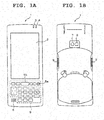
- FIG. 1A and FIG. 1B are external views of a slip processing device 1 according to the first embodiment.
- FIG. 1A is a front view of the slip processing device 1
- FIG. 1B is a rear view of the slip processing device 1.
- the slip processing device 1 is a handy terminal having functions for capturing images of slips, storing the captured images, and acquiring identification information indicated by barcodes on the slips from the captured images.
- the slip processing device 1 is not limited to the handy terminal, and may be any of other information terminal devices such as a tablet PC, note PC, PDA (Personal Digital Assistant), smartphone, and portable telephone.
- the slip processing device 1 has a display 2, a first indicator 3, a second indicator 4, an operation key group 5, and a loudspeaker 6 provided on the front side.
- the display 2 performs screen display of various pieces of information. In addition, it is used for the operation of the slip processing device 1 or data input thereon by an attached stylus.
- the first indicator 3 and the second indicator 4 are LEDs (Light Emitting Diodes) which can emit light in a plurality of colors as required.
- the first indicator 3 is lit in a color in accordance with the state of the power supply of the slip processing device 1.
- the second indicator 4 is lit in green or red when identification information indicated by a barcode and slip image information are acquired.
- the operation key group 5 is constituted by a plurality of keys including a power supply key 5a and a center trigger key 5b.
- the center trigger key 5b is used for slip imaging instructions.
- these plurality keys (reference numerals thereof are omitted in the drawing) constituting the operation key group 5 also include a function key, numerical keys, and the like, which are used in various operations of the slip processing device 1.
- a camera 7 for capturing images of slips and an LED light 8 are provided, as shown in FIG. 1B .
- This camera 7 has an AF (Auto Focus) function.
- side trigger keys 9 provided which are used in slip imaging instructions as with the center trigger key 5b.
- FIG. 2 is a block diagram of the electrical structure of the slip processing device 1.
- the slip processing device 1 is constituted by a CPU (Central Processing Unit) 11, a RAM (Random Access Memory) 12 connected to the CPU 11, a main storage device 13, a recording section 14, a display section 15, a touch panel 16, an indicator section 17, a key input section 18, a camera section 19, a sound emission section 20, and a communication section 21.
- a CPU Central Processing Unit
- RAM Random Access Memory
- the main storage device 13 is constituted by a rewritable non-volatile memory such as a flash memory incorporated in the slip processing device 1. Allocated in the main storage device 13 are a control program area 13a where a control program is stored, a setting information area 13b where various pieces of setting information set by a user regarding the operation of the slip processing device 1 are stored, and an image area 13c where captured images are temporarily stored.
- a control program area 13a where a control program is stored
- a setting information area 13b where various pieces of setting information set by a user regarding the operation of the slip processing device 1 are stored
- an image area 13c where captured images are temporarily stored.
- the slip processing device 1 supports plural types of slips
- the setting information area 13b has stored therein information of plural types of slips (hereinafter referred to as slip information) set in advance by the user.
- the setting information area 13b has stored therein various pieces of setting information including information of imaging target slips set in advance by the user and information regarding the operation of the slip processing device 1.
- the CPU 11 reads out the control program from the main storage device 13, loads it into the RAM 12, and controls the operation of the slip processing device 1 based on this loaded control program.
- the display section 15 is constituted by the display 2 and its drive circuit.
- the display 2 is, for example, an LCD (Liquid Crystal Display) or an ELD (Electro Luminescent Display).
- the touch panel 16 is a pressure-sensitive or electrostatic touch panel integrally provided on the surface of the display 2, and supplies the CPU 11 with information regarding operations by the user.
- the indicator section 17 is constituted by LEDs constituting the first indicator 3 and the second indicator 4 and their drive circuits. This indicator section 17 also includes the LED light 8 and its drive circuit.
- the key input section 18 is constituted by a plurality of keys such as the center trigger key 5b, and supplies the CPU 11 with information regarding operations by the user who is using the slip processing device 1.
- the camera section 19 is constituted by an image sensor, an image processing engine which processes analog signals and digital signals, and a drive circuit which drives an imaging lens at the time of AF.
- the image sensor is, for example, a CMOS (Complementary Metal Oxide Semiconductor) or a CCD (Charge Coupled Device), and its effective pixels are approximately five million (2592 dots x 1944 dots).
- the recording section 14 is constituted by, for example, various memory cards that are attachable and detachable to and from the slip processing device 1 and a card interface allowing the input and output of data to and from these memory cards.
- slip data is stored as needed, which includes a slip image acquired by cutting out a slip portion from a captured image showing a slip, that is, image information regarding the slip, and identification information acquired from a barcode thereon.
- the sound emission section 20 is constituted by a voice generation circuit, an amplifier, and the loudspeaker 6, and emits various notification sounds as required.
- the communication section 21 performs communication with an external data management server 51 by wired or wireless communication as required, and transmits slip data of a plurality of slips stored (saved) in the recording section 14.
- the data management server 51 is a computer which manages a large amount of slip data supplied from a plurality of slip processing devices 1, and the slip data is supplied to the data management server 51 by communication by the communication section 21. Note that, by a memory card as well, slip data can be supplied to the data management server 51. Also, communications between the slip processing device 1 and the data management server 51 can also be performed by an arbitrary communication network.
- the slip processing device 1 is provided with a plurality of operation modes including a slip imaging mode for imaging slips, acquiring slip images, barcode identification information, and slip data, and storing them in the recording section 14, and a data output mode for outputting the slip data stored in the recording section 14 to an external information processing device via the communication section 21.
- FIG. 3 is a diagram showing an example of a slip 101 to be imaged, which is a delivery slip for use by a courier.
- This slip 101 has a laterally-elongated rectangular shape, and its lower side has a sender field 102 where the address, name, and the like of a sender who is a delivery source are written, and a delivery destination field 103 where the address, name, and the like of a delivery destination are written.
- Its upper-right portion has a barcode 104 indicating identification information allocated to this slip 101.
- the actual size of a general slip is smaller than the size of an A4 paper sheet 100 (297 mm in length ⁇ 210 mm in width). For example, it is 115 mm in height ⁇ 230 mm in width, as shown in FIG. 3 .
- the slip 101 is imaged so as to store a slip image, it is required to ensure a predetermined resolution stipulated by the Electronic Books Maintenance Act for that slip image.
- This resolution stipulated by the Electronic Books Maintenance Act is equal to or more than 200 dots for 25.4 mm (one inch), that is, equal to or more than 200 dpi.
- the size of the number of pixels of an image of the A4-size paper sheet 100 is 2,338 dots in length and 1,654 dots in width, and the total number of pixels is 3,867,052.
- the size of the number of pixels of its slip image is 906 dots in length and 1810 dots in width, and the total number of pixels is 1, 639, 860. Accordingly, any structure capable of recording an image of a total number of pixels of four million can support general slips such as the slip 101 exemplarily illustrated in FIG. 3 .
- minimum numbers of slip image pixels in a lengthwise direction and a lateral direction required to store the slip 101 as a slip image of 200 dpi, that is, a reference pixel-count size, and information regarding the position of the barcode 104 on the slip 101 are stored as slip information together with the actual size (lengthwise dimension and lateral dimension).
- the above-described reference size is the number of pixels when the maximum number of pixels (five million pixels) has been set as the number of pixels for an image of the slip 101.
- the information regarding the position of the barcode 104 indicates the written area of the barcode 104 on the slip 101 with reference to, for example, the upper-right corner of this slip 101.
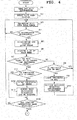
- FIG. 4 and FIG. 5 are flowcharts of processing in the slip imaging mode that is executed by the CPU 11 by following the control program stored in the main storage device 13 (control program area 13a) upon power-up.
- the CPU 11 In the slip imaging mode, the CPU 11 immediately reads out the slip information of a slip specified in advance as an imaging target from the main storage device 13 (setting information area) (Step S1). In addition, the CPU 11 performs live view display, that is, starts to control the camera section 19 to capture images at a predetermined frame rate (for example, 30 fps), and displays the captured images (hereinafter referred to as "live view image") on the display 2 (Step S2).
- a predetermined frame rate for example, 30 fps
- the slip processing device 1 of the present embodiment has been designed to be used in a landscape state at the time of image capturing.
- the live view image G is displayed in a screen center area 2a of the display 2.
- information (not shown) other than the live view image G is displayed, as shown in FIG. 6A and FIG. 6B .
- the CPU 11 recognizes an area Ga corresponding to the slip 101 (hereinafter referred to as "slip area") from the live view image G for each frame (or several frames) sequentially captured (Step S3).
- the recognition of the slip area Ga is performed by, for example, performing edge detection or linear recognition on the live view image G, detecting a plurality of rectangular areas sectioned along a plurality of recognized straight lines, and specifying a rectangular area having the maximum area as the slip area Ga.
- the specification of the slip area Ga may be performed based not only on the areas of the plurality of rectangular areas but also color information of each area.
- the CPU 11 judges whether the slip area Ga has been recognized, that is, whether the recognition of the slip area Ga is successful (Step S4).
- the CPU 11 repeatedly performs this recognition processing on new frames of the live view image G (NO at Step S4).
- the CPU 11 uses an OSD (On Screen Display) function to superimpose a guide frame 111 on a predetermined point on the live view image G (Step S5).
- the CPU 11 sets the display position of the guide frame 111 such that the center of the display position coincides with the center of the slip area Ga.
- the CPU 11 adjusts the display position of the guide frame 111 such that it is positioned close to the slip area Ga within a range where the entire guide frame 111 can be displayed, as shown in FIG. 6B .
- the guide frame 111 is constituted by a rectangular slip frame 112, a rectangular barcode frame 113, and four slip detection points 114 arranged at the four corners of the slip frame 112.
- the slip frame 112 is a frame circumscribed on a rectangular area having a reference size indicated by the slip information, and indicates on the live view image G the minimum size of the slip 101 that can be recorded at a stipulated resolution.
- the barcode frame 113 is a frame indicating an area where the barcode 104 is positioned when an inner area within the slip frame 112 coincides with the slip area Ga.
- the slip detection points 114 at the four corners are marks for assisting a size adjustment task for adjusting the size of the slip 101 in the live view image G when the user captures an image of the slip 101.
- the CPU 11 acquires the size (the numbers of pixels in the lengthwise and lateral directions) of the slip area Ga (Step S5), and judges whether the size is equal to or larger than the reference pixel-count size (hereinafter referred to as "reference size") indicated by the slip information so as to judge whether the number of the pixels in each of the lengthwise and lateral directions is equal to or larger than a reference number of pixels (Step S6). That is, the CPU 11 judges whether the slip area Ga can be recorded at the stipulated resolution or a higher resolution when image capturing is performed at this point.
- reference size the reference pixel-count size indicated by the slip information so as to judge whether the number of the pixels in each of the lengthwise and lateral directions is equal to or larger than a reference number of pixels
- the CPU 11 performs the following processing.
- the CPU 11 judges whether the second indicator 4 (simply mentioned as indicator in FIG. 4 ) has been lit in red (Step S8). When the second indicator 4 has not been lit in red (NO at Step S8), the CPU 11 lights up the second indicator 4 in red (Step S9).
- the CPU 11 causes the sound emission section 20 to output audio guidance that prompts the user to adjust the size of the slip 101 on the live view image G, that is, the viewing angle and the imaging distance (Step S10).
- This audio guidance is a message such as "Please take a larger image of the slip".
- the CPU 11 may guide the user by displaying guidance prompting the adjustment of the viewing angle and the imaging distance on the display section 15.
- the CPU 11 may guide the user by causing the sound emission section 20 to output the audio guidance and displaying the guidance on the display section 15.
- the CPU 11 returns to the processing at Step S3 to repeat it and the processing thereafter.
- the guide frame 111 is moved following the slip area Ga. While the size of the slip area Ga is smaller than the reference size (NO at Step S7), the CPU 11 maintains the lighting of the second indicator 4 in red (YES at Step S8).
- FIG. 7 shows an example of the live view image G when the size of the slip area Ga is equal to or larger than the reference size, in which the slip area Ga is inscribed in the slip frame 112 and positioned at the center of the live view image G.
- the CPU 11 judges whether the second indicator 4 has been lit in green at this point (Step S11). That is, the CPU 11 judges whether the size of the slip area Ga has been judged to be equal to or larger than the reference size in the previous processing.
- the CPU 11 When the indicator has not been lit in green, that is, the indicator has been lit in red (NO at Step S11), the CPU 11 lights up the second indicator 4 in green (Step S12). In addition, by causing the sound emission section 20 to generate a predetermined notification sound, the CPU 11 notifies the user that the stipulated resolution can be ensured for an image of the slip (Step S13).
- the predetermined notification sound is a buzzer sound such as "blip, blip".
- the CPU 11 judges whether an imaging instruction from the user has been received. When no imaging instruction has been received (NO at Step S14), the CPU 11 returns to the processing at Step S3 to repeat it and the processing thereafter. That is, the CPU 11 maintains an imaging wait state.
- the CPU 11 skips each processing at Step S12 and Step S13 to immediately judge whether an imaging instruction has been received from the user (Step S14). Then, until an imaging instruction is received, the CPU 11 returns to the processing at Step S3 to repeat it and the processing thereafter (NO at Step S14).
- the CPU 11 When the size of the slip area Ga becomes smaller than the reference size before an imaging instruction is received from the user (NO at Step S6), the CPU 11 performs the processing at Step S8 to Step S10, that is, lights up the second indicator 4 in red, generates audio guidance prompting the adjustment of the viewing angle and the imaging distance, and thereby notifies the user that an image of the slip can no longer be recorded at the stipulated resolution.
- Step S14 When an imaging instruction is received from the user while the size of the slip area Ga is equal to or larger than the reference (YES at Step S14), the CPU 11 performs AF control in the camera section 19 (Step S15), performs imaging processing for slip image recording (Step S16), and temporarily stores the captured image in the image area 13c of the main storage device 13, as shown in FIG. 5 (Step S17).
- the CPU 11 specifies a barcode area where the barcode 104 is present in the temporarily-stored captured image, and decodes the barcode by an image processing technique to acquire identification information formed of data characters of a prescribed number of digits (Step S18). Then, the CPU 11 stores the acquired identification information in the recording section 14 (Step S19).
- the CPU 11 cuts out the slip area Ga recognized by the processing at Step S3 from the temporarily-stored captured image (Step S20), and stores an image of that area as a slip image in the recording section 14 (Step S21).
- the identification information (data characters) acquired at Step S18 is provided as it is to the image file of the slip image as a file name, so that code information regarding the barcode and the slip image are associated with each other. Then, the CPU 11 ends the series of processing in the slip imaging mode.
- the second indicator 4 is lit in red when a stipulated resolution cannot be ensured for a slip image, and is lit in green when the stipulated resolution can be ensured for a slip image. This allows the user to sequentially know whether a resolution for a slip image at that point satisfies the stipulated resolution and perform image capturing at appropriate imaging timing, whereby an image of the slip 101 can be reliably recorded at the stipulated resolution.
- the user is notified thereof by audio guidance and a notification sound. This also allows an image of the slip 101 to be reliably recorded at the stipulated resolution.
- the color of the light of the second indicator 4 is changed between red and green so as to allow the user to regularly know whether the stipulated resolution can be ensured for a slip image.
- a configuration may be adopted in which an indicator is provided for each state requiring notification and the user is notified of each state individually. In this configuration, the notification of each state by each indicator may be performed only when a current state is changed.
- the user is notified of a judgment result as to whether the stipulated resolution can be ensured for a slip image, by the colors of the light of the second indicator 4, audio guidance, and a notification sound.
- a configuration may be adopted in which the user is notified only by the colors of the light or by audio guidance and a notification sound.
- a configuration may be adopted in which the display color of the guide frame 111 is changed instead of the color of the light of the second indicator 4. Also, a configuration may be adopted in which, when a judgment is made that a stipulated resolution can be ensured for a slip image, the guide frame 111 is temporarily blinked (the display and non-display thereof are alternately performed a predetermined number of times at predetermined time intervals) instead of a notification sound being generated. That is, in the slip imaging mode, the second indicator 4 is not necessarily required to be used, and the user may be notified of a judgment result as to whether a stipulated resolution can be ensured for a slip image, by only the guide frame 111.
- the guide frame 111 is superimposed on the live view image G, and the minimum size of the slip 101 required to acquire the stipulated resolution is presented to the user. Therefore, only by adjusting the size of the slip 101 in the live view image G such that the slip 101 is inscribed in the slip frame 112 or becomes larger, the user can reliably record an image of the slip at the stipulated resolution. As a result of this configuration, a slip image can be reliably and easily captured.
- the display position of the guide frame 111 is adjusted in accordance with the position of the slip 101 in the live view image G. Specifically, the display position of the guide frame 111 is adjusted such that it is positioned close to the slip area Ga within a range where the entire guide frame 111 can be be displayed. This allows the user to more easily and quickly take a slip image.
- the guide frame 111 is to indicate to the user the minimum size of the slip 101 in the live view image G, and is not to indicate an area to be used (cutout) as a slip image. Therefore, there is no harm even if the positions of the slip area Ga and the guide frame 111 have been shifted from each other when an imaging instruction is provided. This also applies to a configuration in which, unlike the present embodiment, a captured image is stored as it is as a slip image.
- the guide frame 111 is only required to indicate the minimum size of the slip 101 in the live view image G to the user. Accordingly, for example, a configuration may be adopted where the barcode frame 113 and the slip detection points 114 are not used and only the slip frame 112 is used. Moreover, although the guide frame 111 is formed of a bold line in the present embodiment, it may be formed of a thin line as long as the guide frame 111 can be identified in the live view image G. Furthermore, the guide frame 111 may be configured such that only the four corners of the slip frame 112, that is, only the four corners of the area of the minimum size of the slip 101 are displayed.
- a slip image an image of a slip portion
- another guide frame for indicating a recommended size of the slip area Ga such as a rectangular frame surrounding the guide frame 111, may be displayed on the live view image G together with the guide frame 111, by which an unnecessary increase in the data amount of a slip image to be finally stored can be prevented.
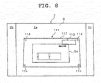
- the shape of the guide frame 111 is not necessarily required to be fixed, and may be deformed in accordance with the shape of the slip area Ga, as shown in FIG. 8 . Note that, even when the slip area Ga is not in a normal shape (rectangle), an image of the slip can be recorded at the stipulated resolution if the number of pixels of each side of the slip area Ga is equal to or larger than the reference number of pixels.
- the guide frame 111 is not necessarily required to be displayed constantly, and a configuration may be adopted in which whether to display the guide frame 111 can be selected by the user as appropriate before the slip processing device 1 is used or during an operation of imaging the slip 101.
- the guide frame 111 indicating the minimum size is superimposed on the live view image G as a guidance indication for the size adjustment of the slip 101 in the live view image G.
- the guide frame 111 can be replaced by another indication having a function to provide a guide for size adjustment.
- the indication may be superimposed on the live view image G, or may be displayed in the screen area 2b, 2c, or the like other than the screen center area 2a of the display 2 separately from the live view image G.
- the minimum size (size of the number of pixels) of the slip 101 in the live view image G or its total number of pixels may be displayed together with the sequentially-changing size of the slip 101 or its total number of pixels, in numerical values.
- an indication clearly displaying a relation between the former size and the latter size to the user may be displayed.
- the slip processing device 1 acquires identification information indicated by a barcode from a captured image of the slip 101.
- the slip processing device 1 may be structured to include a barcode reader dedicated for reading identification information from a barcode separately from the camera 7.
- the slip area Ga is cut out from a captured image and recorded as a slip image.
- a configuration may be adopted in which a captured image is recorded as it is.
- the slip processing device 1 is not required to record slip images, captured images, and the like, and acquired slip images, captured images, and the like may be immediately transmitted to the data management server 51.
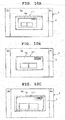
- FIG. 10A to FIG. 10C are diagrams each showing an example of a change in the live view image G in the present embodiment.
- the guide frame 111 is displayed at the center of the live view image G (the screen center area 2a of the display 2) .
- the processing of the CPU 11 in this embodiment is hereinafter specifically described with reference to FIG. 9 .
- the CPU 11 when the processing is started upon power-up, the CPU 11 immediately reads out slip information of a slip specified in advance as an imaging target from the main storage device 13 (setting information area) (Step S101), and starts live view display (Step S102).
- the CPU 11 immediately after starting the live view display, the CPU 11 superimposes the guide frame 111 on the center of the live view image G (the screen center area 2a of the display 2) irrespective of the contents of the live view image G (Step S103).
- the CPU 11 recognizes the slip area Ga in the live view image G for each frame sequentially captured (Step S104). Then, when the slip area Ga is recognized (YES at Step S105), the CPU 11 acquires the size of the recognized slip area Ga (Step S106), and judges whether its size is equal to or larger than the above-described reference size (Step S107).
- the CPU 11 performs processing at Step S108 to Step S114 in accordance with the judgment result.
- the processing at Step S108 to Step S114 is the same as the processing at Step S8 to Step S14 shown in FIG. 4 in the first embodiment, and is therefore not described herein.
- image capturing can be performed only when a stipulated resolution can be ensured for a slip image.
- an image of the slip 101 can be reliably recorded at a stipulated resolution.
- the user adjusts the viewing angle and the imaging distance so that the slip area Ga comes within the guide frame 111 in the live view image G as shown in FIG. 10 .
- the user further adjusts the imaging distance so as to ensure that the slip area Ga internally fits in the guide frame 111 as shown in FIG. 10B or that the slip area Ga is larger than the guide frame 111 as shown in FIG. 10C .
- the user performs image capturing.
- the CPU 11 performs processing of notifying the user of a judgment result as to whether a stipulated resolution can be ensured for a slip image, not by the display color of the second indicator 4 but by the display color of the guide frame 111.
- FIG. 12A to FIG. 12C are diagrams showing an example of a change in the live view image G in the present embodiment.
- the slip 101 comes within the viewing angle, only the live view image G is displayed in the screen center area 2a of the display 2, as shown in FIG. 12A .
- the guide frame 111 is superimposed on the live view image G, as shown in FIG. 12B and FIG. 12C .
- the size of the guide frame 111 is sequentially changed so that the guide frame 111 externally fits on the slip area Ga, and its display position is controlled to follow the slip area Ga, whereby the guide frame 111 is controlled to always externally fits on the slip area Ga.
- the slip detection points 114 of the guide frame 111 have been omitted.
- the display color of the guide frame 111 is red (black in the drawing) if the size of the slip area Ga is smaller than the above-described reference size, as shown in FIG. 12B . Also, the display color of the guide frame 111 is green (hatched in the drawing) if the size of the slip area Ga is equal to or larger than the above-described reference size, as shown in FIG. 12C .
- the processing of the CPU 11 in this embodiment is hereinafter specifically described with reference to FIG. 11 .
- the processing at Step S201 to Step S204 is the same as the processing at Step S1 to Step S4 shown in FIG. 4 in the first embodiment, and is therefore not described herein.
- the CPU 11 when the slip area Ga is recognized in the live view image G (YES at Step S204), the CPU 11 immediately acquires the size of the slip area Ga, and determines the size and the display position of the guide frame 111 (Step S206).
- a size at which the guide frame 111 externally fits on the slip area Ga is determined as the size of the guide frame 111
- a position where the guide frame 111 externally fits on the slip area Ga is determined as the display position of the guide frame 111.
- the guide frame 111 may be formed of a thin line and, in this case, the size of the guide frame 111 is equal to the size of the slip area Ga.
- the CPU 11 judges whether the size of the slip area Ga is equal to or larger than the above-described reference size (Step S208), and performs the following processing in accordance with the result.
- the CPU 11 displays the guide frame 111 in red and superimposes it on the live view image G (Step S210).
- the size and the display position of the guide frame 111 are the size and the position determined in the processing at Step S206.
- the CPU 11 controls the sound emission section 20 to output audio guidance which is the same as that in the first embodiment and prompts the user to adjust the viewing angle and the imaging distance (Step S211), and then returns to the processing at Step S203 to repeat it and the processing thereafter.
- Step S209 when the guide frame 111 is being displayed in red at that point (YES at Step S209), the CPU 11 omits the processing at Step S210 and Step S211 to immediately return to the processing at Step S203, and repeats it and the processing thereafter.
- Step S208 when the size of the slip area Ga is equal to or larger than the reference size (YES at Step S208) and the guide frame 111 is not being displayed in green at that point (NO at Step S209), the CPU 11 displays the guide frame 111 in green and superimposes it on the live view image G (Step S213).
- the size and the display position of the guide frame 111 are the size and the position determined in the processing at Step S206.
- the CPU 11 controls the sound emission section 20 to generate a predetermined notification sound which is the same as that in the first embodiment and notifies the user that a stipulated resolution can be ensured for a slip image (Step S214). Thereafter, the CPU 11 judges whether an imaging instruction has been received from the user. When no imaging instruction has been received (NO at Step S215), the CPU 11 returns to the processing at Step S203 to repeat it and the processing thereafter.
- the CPU 11 omits the processing at Step S213 and Step S214 to immediately judge whether an imaging instruction has been received from the user.
- the CPU 11 returns to the processing at Step S203 to repeat it and the processing thereafter.
- Step S203 While the CPU 11 is repeating the processing at Step S203 and the processing thereafter, when the slip area Ga is no longer recognized in the live view image G (NO at Step S204) and the guide frame 111 is being displayed in red or green at that point (YES at Step S205), the CPU 11 once stops the display of the guide frame 111 (Step S206), and then returns to the processing at Step S203 to repeat it and the processing thereafter.
- the CPU 11 When an imaging instruction is received from the user while the size of the slip area Ga is equal to or larger the reference size (while the guide frame 111 is in green) (YES at Step S215), the CPU 11 performs the processing of FIG. 5 described in the first embodiment, and ends a series of processing in the slip imaging mode.
- the guide frame 111 is displayed in green (or is changed from red to green) when image capturing for the slip 101 is performed, which allows the user to know whether a resolution for a slip image satisfies a stipulated resolution.
- the image capturing can be performed at appropriate imaging timing, and an image of the slip 101 can be reliably recorded at the stipulated resolution.
- the size of the guide frame 111 is sequentially changed to a size at which the guide frame 111 externally fits on the slip area Ga (which may be a size equal to the size of the slip area Ga), and its display position follows the slip area Ga, whereby the guide frame 111 is controlled to always externally fit on the slip area Ga.
- This configuration allows the user to easily perform the size adjustment of the slip (the adjustment of the viewing angle and the imaging distance) regardless of the position of the slip area Ga in the live view image G.
- the shape of the guide frame 111 is not necessarily required to be fixed, and may be deformed in accordance with the shape of the slip area Ga as shown in FIG. 8 .
- imaging targets in the present invention are not limited to the slip 101, and may be other ledger documents.
- the present invention is not limited to a handy terminal and the like, and can be applied to other information terminal devices which capture an image of a ledger document and acquires its image information, such as a smartphone, tablet PC (Personal Computer), notebook PC, and PDA (Personal Digital Assistant).
Landscapes
- Engineering & Computer Science (AREA)
- Physics & Mathematics (AREA)
- Computer Vision & Pattern Recognition (AREA)
- Theoretical Computer Science (AREA)
- General Physics & Mathematics (AREA)
- Multimedia (AREA)
- Artificial Intelligence (AREA)
- Electromagnetism (AREA)
- Health & Medical Sciences (AREA)
- General Health & Medical Sciences (AREA)
- Toxicology (AREA)
- Signal Processing (AREA)
- Computer Graphics (AREA)
- Geometry (AREA)
- Studio Devices (AREA)
Abstract
Description
- The present invention relates to a ledger document processing device, ledger document processing method and storage medium.
- Conventionally, a handy terminal that serves as a slip processing device for business use has been known. For example, there is a handy terminal that includes a barcode scanner and a camera and acquires, from each slip, identification information included in a barcode printed on the slip and image information regarding an image of the slip captured by the camera.
- Also, as a method for associating identification information included in a barcode printed on a slip with image information acquired by image capturing by a digital camera for data management, a management method is known in which a barcode is first read out by a barcode scanner so as to acquire identification information and then an image of a target is captured by a digital camera so as to associate the identification information with the image information (for example, refer to Japanese Patent Application Laid-Open (Kokai) Publication No.
11-349114 - In the Electronic Books Maintenance Act, ledger documents such as receipts, statements of delivery, slips, and invoices are permitted to be read out by a scanner and stored as image information. In recent years, by the relaxation of requirements of image information acquirement under law revisions, it is permitted to use a smartphone, digital camera, or the like to acquire image information regarding a ledger document if a stipulated resolution is satisfied.
- However, in a case where a slip processing device such as a handy terminal is used to capture images of slips to store the slips as image information, the resolutions of the image information are not consistent depending on the imaging distances, the viewing angles, and the like. In addition, it is difficult for the user to evaluate the resolutions. That is, it is difficult to ensure the stipulated resolution for final image information to be recorded.
- In accordance with one aspect of the present invention, there is provided a ledger document processing device comprising: a display section which displays a live view image captured by an imaging section while waiting for a ledger document to be captured; and a processor which actualizes functions comprising: judging whether a pixel-count size of an area corresponding to the ledger document in an image to be captured and stored in response to an imaging instruction is equal to or larger than a reference pixel-count size while waiting for the ledger document to be captured; notifying a user of a judgment result; and storing in a storage section the image captured by the imaging section in response to the imaging instruction.
- In accordance with another aspect of the present invention, there is provided a ledger document processing method comprising: displaying a live view image captured by an imaging section while waiting for a ledger document to be captured; judging whether a pixel-count size of an area corresponding to the ledger document in an image to be captured and stored in response to an imaging instruction is equal to or larger than a reference pixel-count size while waiting for the ledger document to be captured; notifying a user of a judgment result; and storing the image captured by the imaging section in response to the imaging instruction.
- In accordance with another aspect of the present invention, there is provided a non-transitory computer-readable storage medium having stored thereon a program that is executable by a computer in a ledger document processing device to actualize functions comprising: displaying a live view image captured by an imaging section on a display section while waiting for a ledger document to be captured; judging whether a pixel-count size of an area corresponding to the ledger document in an image to be captured and stored in response to an imaging instruction is equal to or larger than a reference pixel-count size while waiting for the ledger document to be captured; notifying a user of a judgment result; and storing in a storage section the image captured by the imaging section in response to the imaging instruction.
- The above and further objects and novel features of the present invention will more fully appear from the following detailed description when the same is read in conjunction with the accompanying drawings. It is to be expressly understood, however, that the drawings are for the purpose of illustration only and are not intended as a definition of the limits of the invention.
- The present invention can be more clearly understood by the detailed description below being considered together with the following drawings.
-
FIG. 1A and FIG. 1B are external views of a slip processing device according to a first embodiment, of whichFIG. 1A is a front view andFIG. 1B is a rear view; -
FIG. 2 is a block diagram of the electrical structure of the slip processing device; -
FIG. 3 is a diagram showing an example of a slip to be imaged; -
FIG. 4 is a flowchart of processing in a slip imaging mode; -
FIG. 5 is a flowchart following that ofFIG. 4 ; -
FIG. 6A and FIG. 6B are diagrams each showing an example of a live view image when the size of a slip area is smaller than a reference size; -
FIG. 7 is a diagram showing an example of a live view image when the size of the slip area is equal to or larger than the reference size; -
FIG. 8 is a diagram showing a modification example of a guide frame based on the shape of the slip area; -
FIG. 9 is a flowchart of processing in a slip imaging mode in a second embodiment; -
FIG. 10A to FIG. 10C are diagrams showing an example of a change in a live view image in the second embodiment; -
FIG. 11 is a flowchart of processing in a slip imaging mode in a third embodiment; and -
FIG. 12A to FIG. 12C are diagrams showing an example of a change in a live view image in the third embodiment. - A first embodiment of the present invention will hereinafter be described.
FIG. 1A and FIG. 1B are external views of aslip processing device 1 according to the first embodiment.FIG. 1A is a front view of theslip processing device 1, andFIG. 1B is a rear view of theslip processing device 1. - The
slip processing device 1 is a handy terminal having functions for capturing images of slips, storing the captured images, and acquiring identification information indicated by barcodes on the slips from the captured images. - The
slip processing device 1 is not limited to the handy terminal, and may be any of other information terminal devices such as a tablet PC, note PC, PDA (Personal Digital Assistant), smartphone, and portable telephone. - As shown in
FIG. 1A , theslip processing device 1 has adisplay 2, afirst indicator 3, asecond indicator 4, an operationkey group 5, and aloudspeaker 6 provided on the front side. - The
display 2 performs screen display of various pieces of information. In addition, it is used for the operation of theslip processing device 1 or data input thereon by an attached stylus. Thefirst indicator 3 and thesecond indicator 4 are LEDs (Light Emitting Diodes) which can emit light in a plurality of colors as required. Thefirst indicator 3 is lit in a color in accordance with the state of the power supply of theslip processing device 1. Thesecond indicator 4 is lit in green or red when identification information indicated by a barcode and slip image information are acquired. - The operation
key group 5 is constituted by a plurality of keys including a power supply key 5a and a center trigger key 5b. The center trigger key 5b is used for slip imaging instructions. Note that these plurality keys (reference numerals thereof are omitted in the drawing) constituting theoperation key group 5 also include a function key, numerical keys, and the like, which are used in various operations of theslip processing device 1. - Also, on the rear side of the
slip processing device 1, acamera 7 for capturing images of slips and anLED light 8 are provided, as shown inFIG. 1B . Thiscamera 7 has an AF (Auto Focus) function. Moreover, on the side surfaces of theslip processing device 1,side trigger keys 9 provided which are used in slip imaging instructions as with the center trigger key 5b. -
FIG. 2 is a block diagram of the electrical structure of theslip processing device 1. Theslip processing device 1 is constituted by a CPU (Central Processing Unit) 11, a RAM (Random Access Memory) 12 connected to theCPU 11, amain storage device 13, arecording section 14, adisplay section 15, atouch panel 16, anindicator section 17, akey input section 18, acamera section 19, asound emission section 20, and acommunication section 21. - The
main storage device 13 is constituted by a rewritable non-volatile memory such as a flash memory incorporated in theslip processing device 1. Allocated in themain storage device 13 are acontrol program area 13a where a control program is stored, a settinginformation area 13b where various pieces of setting information set by a user regarding the operation of theslip processing device 1 are stored, and animage area 13c where captured images are temporarily stored. - Here, the
slip processing device 1 supports plural types of slips, and the settinginformation area 13b has stored therein information of plural types of slips (hereinafter referred to as slip information) set in advance by the user. Also, the settinginformation area 13b has stored therein various pieces of setting information including information of imaging target slips set in advance by the user and information regarding the operation of theslip processing device 1. - The
CPU 11 reads out the control program from themain storage device 13, loads it into theRAM 12, and controls the operation of theslip processing device 1 based on this loaded control program. - The
display section 15 is constituted by thedisplay 2 and its drive circuit. Thedisplay 2 is, for example, an LCD (Liquid Crystal Display) or an ELD (Electro Luminescent Display). Thetouch panel 16 is a pressure-sensitive or electrostatic touch panel integrally provided on the surface of thedisplay 2, and supplies theCPU 11 with information regarding operations by the user. - The
indicator section 17 is constituted by LEDs constituting thefirst indicator 3 and thesecond indicator 4 and their drive circuits. Thisindicator section 17 also includes theLED light 8 and its drive circuit. Thekey input section 18 is constituted by a plurality of keys such as the center trigger key 5b, and supplies theCPU 11 with information regarding operations by the user who is using theslip processing device 1. - The
camera section 19 is constituted by an image sensor, an image processing engine which processes analog signals and digital signals, and a drive circuit which drives an imaging lens at the time of AF. The image sensor is, for example, a CMOS (Complementary Metal Oxide Semiconductor) or a CCD (Charge Coupled Device), and its effective pixels are approximately five million (2592 dots x 1944 dots). - The
recording section 14 is constituted by, for example, various memory cards that are attachable and detachable to and from theslip processing device 1 and a card interface allowing the input and output of data to and from these memory cards. In therecording section 14, slip data is stored as needed, which includes a slip image acquired by cutting out a slip portion from a captured image showing a slip, that is, image information regarding the slip, and identification information acquired from a barcode thereon. - The
sound emission section 20 is constituted by a voice generation circuit, an amplifier, and theloudspeaker 6, and emits various notification sounds as required. Thecommunication section 21 performs communication with an externaldata management server 51 by wired or wireless communication as required, and transmits slip data of a plurality of slips stored (saved) in therecording section 14. - The
data management server 51 is a computer which manages a large amount of slip data supplied from a plurality ofslip processing devices 1, and the slip data is supplied to thedata management server 51 by communication by thecommunication section 21. Note that, by a memory card as well, slip data can be supplied to thedata management server 51. Also, communications between theslip processing device 1 and thedata management server 51 can also be performed by an arbitrary communication network. - The
slip processing device 1 is provided with a plurality of operation modes including a slip imaging mode for imaging slips, acquiring slip images, barcode identification information, and slip data, and storing them in therecording section 14, and a data output mode for outputting the slip data stored in therecording section 14 to an external information processing device via thecommunication section 21. - Next, a slip to be imaged by the
slip processing device 1 is described.FIG. 3 is a diagram showing an example of aslip 101 to be imaged, which is a delivery slip for use by a courier. Thisslip 101 has a laterally-elongated rectangular shape, and its lower side has asender field 102 where the address, name, and the like of a sender who is a delivery source are written, and adelivery destination field 103 where the address, name, and the like of a delivery destination are written. Its upper-right portion has a barcode 104 indicating identification information allocated to thisslip 101. - Here, the actual size of a general slip is smaller than the size of an A4 paper sheet 100 (297 mm in length × 210 mm in width). For example, it is 115 mm in height × 230 mm in width, as shown in
FIG. 3 . - In a case where the
slip 101 is imaged so as to store a slip image, it is required to ensure a predetermined resolution stipulated by the Electronic Books Maintenance Act for that slip image. This resolution stipulated by the Electronic Books Maintenance Act is equal to or more than 200 dots for 25.4 mm (one inch), that is, equal to or more than 200 dpi. - In the case of a resolution of 200 dpi, the size of the number of pixels of an image of the A4-
size paper sheet 100 is 2,338 dots in length and 1,654 dots in width, and the total number of pixels is 3,867,052. Also, when theslip 101 has an actual size shown inFIG. 3 , the size of the number of pixels of its slip image is 906 dots in length and 1810 dots in width, and the total number of pixels is 1, 639, 860. Accordingly, any structure capable of recording an image of a total number of pixels of four million can support general slips such as theslip 101 exemplarily illustrated inFIG. 3 . - In the setting
information area 13b of themain storage device 13, minimum numbers of slip image pixels in a lengthwise direction and a lateral direction required to store theslip 101 as a slip image of 200 dpi, that is, a reference pixel-count size, and information regarding the position of the barcode 104 on theslip 101 are stored as slip information together with the actual size (lengthwise dimension and lateral dimension). - Note that the above-described reference size is the number of pixels when the maximum number of pixels (five million pixels) has been set as the number of pixels for an image of the
slip 101. Also, the information regarding the position of the barcode 104 indicates the written area of the barcode 104 on theslip 101 with reference to, for example, the upper-right corner of thisslip 101. - Next, the operation of the
slip processing device 1 according to the present invention will be described when a user thereof uses theslip processing device 1 to capture an image of a slip.FIG. 4 andFIG. 5 are flowcharts of processing in the slip imaging mode that is executed by theCPU 11 by following the control program stored in the main storage device 13 (control program area 13a) upon power-up. - In the slip imaging mode, the
CPU 11 immediately reads out the slip information of a slip specified in advance as an imaging target from the main storage device 13 (setting information area) (Step S1). In addition, theCPU 11 performs live view display, that is, starts to control thecamera section 19 to capture images at a predetermined frame rate (for example, 30 fps), and displays the captured images (hereinafter referred to as "live view image") on the display 2 (Step S2). - Note that the
slip processing device 1 of the present embodiment has been designed to be used in a landscape state at the time of image capturing. The live view image G is displayed in ascreen center area 2a of thedisplay 2. Onother screen areas display 2, information (not shown) other than the live view image G is displayed, as shown inFIG. 6A and FIG. 6B . - Next, the
CPU 11 recognizes an area Ga corresponding to the slip 101 (hereinafter referred to as "slip area") from the live view image G for each frame (or several frames) sequentially captured (Step S3). The recognition of the slip area Ga is performed by, for example, performing edge detection or linear recognition on the live view image G, detecting a plurality of rectangular areas sectioned along a plurality of recognized straight lines, and specifying a rectangular area having the maximum area as the slip area Ga. Note that the specification of the slip area Ga may be performed based not only on the areas of the plurality of rectangular areas but also color information of each area. - Then, the
CPU 11 judges whether the slip area Ga has been recognized, that is, whether the recognition of the slip area Ga is successful (Step S4). Here, until the slip area Ga is recognized, theCPU 11 repeatedly performs this recognition processing on new frames of the live view image G (NO at Step S4). Once the slip area Ga is recognized (YES at Step S4), theCPU 11 uses an OSD (On Screen Display) function to superimpose aguide frame 111 on a predetermined point on the live view image G (Step S5). Here, theCPU 11 sets the display position of theguide frame 111 such that the center of the display position coincides with the center of the slip area Ga. Here, if theentire guide frame 111 cannot be displayed within the live view image G, theCPU 11 adjusts the display position of theguide frame 111 such that it is positioned close to the slip area Ga within a range where theentire guide frame 111 can be displayed, as shown inFIG. 6B . - The
guide frame 111 is constituted by arectangular slip frame 112, arectangular barcode frame 113, and four slip detection points 114 arranged at the four corners of theslip frame 112. - The
slip frame 112 is a frame circumscribed on a rectangular area having a reference size indicated by the slip information, and indicates on the live view image G the minimum size of theslip 101 that can be recorded at a stipulated resolution. - The
barcode frame 113 is a frame indicating an area where the barcode 104 is positioned when an inner area within theslip frame 112 coincides with the slip area Ga. The slip detection points 114 at the four corners are marks for assisting a size adjustment task for adjusting the size of theslip 101 in the live view image G when the user captures an image of theslip 101. - Then, the
CPU 11 acquires the size (the numbers of pixels in the lengthwise and lateral directions) of the slip area Ga (Step S5), and judges whether the size is equal to or larger than the reference pixel-count size (hereinafter referred to as "reference size") indicated by the slip information so as to judge whether the number of the pixels in each of the lengthwise and lateral directions is equal to or larger than a reference number of pixels (Step S6). That is, theCPU 11 judges whether the slip area Ga can be recorded at the stipulated resolution or a higher resolution when image capturing is performed at this point. - Here, when the size of the slip area Ga is not equal to or larger than the reference size, that is, the number of the pixels in one of the lengthwise and lateral directions is smaller than the reference number of pixels (NO at Step S7), the
CPU 11 performs the following processing. - First, the
CPU 11 judges whether the second indicator 4 (simply mentioned as indicator inFIG. 4 ) has been lit in red (Step S8). When thesecond indicator 4 has not been lit in red (NO at Step S8), theCPU 11 lights up thesecond indicator 4 in red (Step S9). In addition, theCPU 11 causes thesound emission section 20 to output audio guidance that prompts the user to adjust the size of theslip 101 on the live view image G, that is, the viewing angle and the imaging distance (Step S10). This audio guidance is a message such as "Please take a larger image of the slip". Here, theCPU 11 may guide the user by displaying guidance prompting the adjustment of the viewing angle and the imaging distance on thedisplay section 15. - Also, the
CPU 11 may guide the user by causing thesound emission section 20 to output the audio guidance and displaying the guidance on thedisplay section 15. - Then, the
CPU 11 returns to the processing at Step S3 to repeat it and the processing thereafter. As a result, theguide frame 111 is moved following the slip area Ga. While the size of the slip area Ga is smaller than the reference size (NO at Step S7), theCPU 11 maintains the lighting of thesecond indicator 4 in red (YES at Step S8). - Then, when the size of the slip area Ga becomes equal to or larger than the reference size by the adjustment of the size of the
slip 101 by the user (YES at Step S7), theCPU 11 performs the following processing.FIG. 7 shows an example of the live view image G when the size of the slip area Ga is equal to or larger than the reference size, in which the slip area Ga is inscribed in theslip frame 112 and positioned at the center of the live view image G. - When the size of the slip area Ga becomes equal to or larger than the reference size as described above, the
CPU 11 judges whether thesecond indicator 4 has been lit in green at this point (Step S11). That is, theCPU 11 judges whether the size of the slip area Ga has been judged to be equal to or larger than the reference size in the previous processing. - When the indicator has not been lit in green, that is, the indicator has been lit in red (NO at Step S11), the
CPU 11 lights up thesecond indicator 4 in green (Step S12). In addition, by causing thesound emission section 20 to generate a predetermined notification sound, theCPU 11 notifies the user that the stipulated resolution can be ensured for an image of the slip (Step S13). The predetermined notification sound is a buzzer sound such as "blip, blip". - Then, the
CPU 11 judges whether an imaging instruction from the user has been received. When no imaging instruction has been received (NO at Step S14), theCPU 11 returns to the processing at Step S3 to repeat it and the processing thereafter. That is, theCPU 11 maintains an imaging wait state. - If the
second indicator 4 has been lit in green when the size of the slip area Ga becomes equal to or larger than the reference size (YES at Step S11), theCPU 11 skips each processing at Step S12 and Step S13 to immediately judge whether an imaging instruction has been received from the user (Step S14). Then, until an imaging instruction is received, theCPU 11 returns to the processing at Step S3 to repeat it and the processing thereafter (NO at Step S14). - When the size of the slip area Ga becomes smaller than the reference size before an imaging instruction is received from the user (NO at Step S6), the
CPU 11 performs the processing at Step S8 to Step S10, that is, lights up thesecond indicator 4 in red, generates audio guidance prompting the adjustment of the viewing angle and the imaging distance, and thereby notifies the user that an image of the slip can no longer be recorded at the stipulated resolution. - When an imaging instruction is received from the user while the size of the slip area Ga is equal to or larger than the reference (YES at Step S14), the
CPU 11 performs AF control in the camera section 19 (Step S15), performs imaging processing for slip image recording (Step S16), and temporarily stores the captured image in theimage area 13c of themain storage device 13, as shown inFIG. 5 (Step S17). - Next, based on position information indicated by the slip information, the
CPU 11 specifies a barcode area where the barcode 104 is present in the temporarily-stored captured image, and decodes the barcode by an image processing technique to acquire identification information formed of data characters of a prescribed number of digits (Step S18). Then, theCPU 11 stores the acquired identification information in the recording section 14 (Step S19). - In addition, the
CPU 11 cuts out the slip area Ga recognized by the processing at Step S3 from the temporarily-stored captured image (Step S20), and stores an image of that area as a slip image in the recording section 14 (Step S21). Here, the identification information (data characters) acquired at Step S18 is provided as it is to the image file of the slip image as a file name, so that code information regarding the barcode and the slip image are associated with each other. Then, theCPU 11 ends the series of processing in the slip imaging mode. - As described above, in the
slip processing device 1 operating in the slip imaging mode, thesecond indicator 4 is lit in red when a stipulated resolution cannot be ensured for a slip image, and is lit in green when the stipulated resolution can be ensured for a slip image. This allows the user to sequentially know whether a resolution for a slip image at that point satisfies the stipulated resolution and perform image capturing at appropriate imaging timing, whereby an image of theslip 101 can be reliably recorded at the stipulated resolution. - Also, at timing at which whether the stipulated resolution can be ensured for a slip image is judged for the first time and timing at which the judgment result is changed, the user is notified thereof by audio guidance and a notification sound. This also allows an image of the
slip 101 to be reliably recorded at the stipulated resolution. - In the above-described configuration, the color of the light of the
second indicator 4 is changed between red and green so as to allow the user to regularly know whether the stipulated resolution can be ensured for a slip image. However, a configuration may be adopted in which an indicator is provided for each state requiring notification and the user is notified of each state individually. In this configuration, the notification of each state by each indicator may be performed only when a current state is changed. - Also, in the above-described configuration, the user is notified of a judgment result as to whether the stipulated resolution can be ensured for a slip image, by the colors of the light of the
second indicator 4, audio guidance, and a notification sound. However, a configuration may be adopted in which the user is notified only by the colors of the light or by audio guidance and a notification sound. - Moreover, a configuration may be adopted in which the display color of the
guide frame 111 is changed instead of the color of the light of thesecond indicator 4. Also, a configuration may be adopted in which, when a judgment is made that a stipulated resolution can be ensured for a slip image, theguide frame 111 is temporarily blinked (the display and non-display thereof are alternately performed a predetermined number of times at predetermined time intervals) instead of a notification sound being generated. That is, in the slip imaging mode, thesecond indicator 4 is not necessarily required to be used, and the user may be notified of a judgment result as to whether a stipulated resolution can be ensured for a slip image, by only theguide frame 111. - In the present embodiment, the
guide frame 111 is superimposed on the live view image G, and the minimum size of theslip 101 required to acquire the stipulated resolution is presented to the user. Therefore, only by adjusting the size of theslip 101 in the live view image G such that theslip 101 is inscribed in theslip frame 112 or becomes larger, the user can reliably record an image of the slip at the stipulated resolution. As a result of this configuration, a slip image can be reliably and easily captured. - Also, the display position of the
guide frame 111 is adjusted in accordance with the position of theslip 101 in the live view image G. Specifically, the display position of theguide frame 111 is adjusted such that it is positioned close to the slip area Ga within a range where theentire guide frame 111 can be be displayed. This allows the user to more easily and quickly take a slip image. - Note that the
guide frame 111 is to indicate to the user the minimum size of theslip 101 in the live view image G, and is not to indicate an area to be used (cutout) as a slip image. Therefore, there is no harm even if the positions of the slip area Ga and theguide frame 111 have been shifted from each other when an imaging instruction is provided. This also applies to a configuration in which, unlike the present embodiment, a captured image is stored as it is as a slip image. - Also, the
guide frame 111 is only required to indicate the minimum size of theslip 101 in the live view image G to the user. Accordingly, for example, a configuration may be adopted where thebarcode frame 113 and the slip detection points 114 are not used and only theslip frame 112 is used. Moreover, although theguide frame 111 is formed of a bold line in the present embodiment, it may be formed of a thin line as long as theguide frame 111 can be identified in the live view image G. Furthermore, theguide frame 111 may be configured such that only the four corners of theslip frame 112, that is, only the four corners of the area of the minimum size of theslip 101 are displayed. - In the present embodiment, it is only required that a stipulated resolution is ensured for a slip image (an image of a slip portion) to be finally stored. On the other hand, if a large image of the
slip 101 more than required is captured, its data amount is needlessly increased. Therefore, another guide frame for indicating a recommended size of the slip area Ga, such as a rectangular frame surrounding theguide frame 111, may be displayed on the live view image G together with theguide frame 111, by which an unnecessary increase in the data amount of a slip image to be finally stored can be prevented. - In this case, by a configuration being adopted in which image capturing can be performed only when the size of the slip area Ga is equal to or larger than (inside) the
guide frame 111 and equal to or smaller than the size of the above-described other guide frame, an unnecessary increase in the data amount of a slip image to be finally stored can be reliably prevented. - Also, the shape of the
guide frame 111 is not necessarily required to be fixed, and may be deformed in accordance with the shape of the slip area Ga, as shown inFIG. 8 . Note that, even when the slip area Ga is not in a normal shape (rectangle), an image of the slip can be recorded at the stipulated resolution if the number of pixels of each side of the slip area Ga is equal to or larger than the reference number of pixels. - Moreover, the
guide frame 111 is not necessarily required to be displayed constantly, and a configuration may be adopted in which whether to display theguide frame 111 can be selected by the user as appropriate before theslip processing device 1 is used or during an operation of imaging theslip 101. - Furthermore, in the present embodiment, the
guide frame 111 indicating the minimum size is superimposed on the live view image G as a guidance indication for the size adjustment of theslip 101 in the live view image G. However, the present invention is not limited thereto. Theguide frame 111 can be replaced by another indication having a function to provide a guide for size adjustment. In this case, the indication may be superimposed on the live view image G, or may be displayed in thescreen area screen center area 2a of thedisplay 2 separately from the live view image G. - For example, as an indication for providing a guide for size adjustment, the minimum size (size of the number of pixels) of the
slip 101 in the live view image G or its total number of pixels may be displayed together with the sequentially-changing size of theslip 101 or its total number of pixels, in numerical values. Also, as an indication for providing a guide for size adjustment, an indication clearly displaying a relation between the former size and the latter size to the user may be displayed. - Still further, in the present embodiment, the
slip processing device 1 acquires identification information indicated by a barcode from a captured image of theslip 101. However, the present invention is not limited thereto. Theslip processing device 1 may be structured to include a barcode reader dedicated for reading identification information from a barcode separately from thecamera 7. Yet still further, in the present embodiment, the slip area Ga is cut out from a captured image and recorded as a slip image. However, a configuration may be adopted in which a captured image is recorded as it is. - Yet still further, in a configuration where the
slip processing device 1 is used with it being constantly connected to thedata management server 51, theslip processing device 1 is not required to record slip images, captured images, and the like, and acquired slip images, captured images, and the like may be immediately transmitted to thedata management server 51. - Next, a second embodiment of the present invention is described. In this embodiment, in the
slip processing device 1 configured as described in the first embodiment, theCPU 11 performs processing of constantly and fixedly displaying theguide frame 111 irrespective of the position of the slip 101 (slip area Ga) in the live view image G.FIG. 10A to FIG. 10C are diagrams each showing an example of a change in the live view image G in the present embodiment. In the present embodiment, theguide frame 111 is displayed at the center of the live view image G (thescreen center area 2a of the display 2) . - The processing of the
CPU 11 in this embodiment is hereinafter specifically described with reference toFIG. 9 . In the present embodiment as well, when the processing is started upon power-up, theCPU 11 immediately reads out slip information of a slip specified in advance as an imaging target from the main storage device 13 (setting information area) (Step S101), and starts live view display (Step S102). - In the present embodiment, immediately after starting the live view display, the
CPU 11 superimposes theguide frame 111 on the center of the live view image G (thescreen center area 2a of the display 2) irrespective of the contents of the live view image G (Step S103). - Subsequently, the
CPU 11 recognizes the slip area Ga in the live view image G for each frame sequentially captured (Step S104). Then, when the slip area Ga is recognized (YES at Step S105), theCPU 11 acquires the size of the recognized slip area Ga (Step S106), and judges whether its size is equal to or larger than the above-described reference size (Step S107). - Thereafter, the
CPU 11 performs processing at Step S108 to Step S114 in accordance with the judgment result. Here, as evident from the drawing, the processing at Step S108 to Step S114 is the same as the processing at Step S8 to Step S14 shown inFIG. 4 in the first embodiment, and is therefore not described herein. As a result, in the present embodiment as well, image capturing can be performed only when a stipulated resolution can be ensured for a slip image. - Thereafter, when an imaging instruction is received from the user during a period in which the size of the slip area Ga in the live view image G is equal to or larger than the reference size (while the
second indicator 4 is lit in green) (YES at Step S114), theCPU 11 performs the processing ofFIG. 5 described in the first embodiment, and then ends the series of processing in the slip imaging mode. - As a result of the above-described configuration, in the present embodiment, when the user performs image capturing for the
slip 101 while following the procedure described below, an image of theslip 101 can be reliably recorded at a stipulated resolution. First, the user adjusts the viewing angle and the imaging distance so that the slip area Ga comes within theguide frame 111 in the live view image G as shown inFIG. 10 . Next, the user further adjusts the imaging distance so as to ensure that the slip area Ga internally fits in theguide frame 111 as shown inFIG. 10B or that the slip area Ga is larger than theguide frame 111 as shown inFIG. 10C . Then, in this state, the user performs image capturing. - Note that, in this embodiment as well, its configuration except the fixed display of the
guide frame 111 can be changed as described in the first embodiment when necessary. - Next, a third embodiment of the present invention is described. In this embodiment, in the
slip processing device 1 configured as described in the first embodiment, theCPU 11 performs processing of notifying the user of a judgment result as to whether a stipulated resolution can be ensured for a slip image, not by the display color of thesecond indicator 4 but by the display color of theguide frame 111. - Here, differences between the present embodiment and the first and second embodiments are first described with reference to
FIG. 12A to FIG. 12C. FIG. 12A to FIG. 12C are diagrams showing an example of a change in the live view image G in the present embodiment. In the present embodiment, until theslip 101 comes within the viewing angle, only the live view image G is displayed in thescreen center area 2a of thedisplay 2, as shown inFIG. 12A . - Also, while the slip area Ga is present in the live view image G, the
guide frame 111 is superimposed on the live view image G, as shown inFIG. 12B and FIG. 12C . Here, the size of theguide frame 111 is sequentially changed so that theguide frame 111 externally fits on the slip area Ga, and its display position is controlled to follow the slip area Ga, whereby theguide frame 111 is controlled to always externally fits on the slip area Ga. InFIG. 12B and FIG. 12C , the slip detection points 114 of theguide frame 111 have been omitted. - Moreover, when the
guide frame 111 is being displayed, the display color of theguide frame 111 is red (black in the drawing) if the size of the slip area Ga is smaller than the above-described reference size, as shown inFIG. 12B . Also, the display color of theguide frame 111 is green (hatched in the drawing) if the size of the slip area Ga is equal to or larger than the above-described reference size, as shown inFIG. 12C . - The processing of the
CPU 11 in this embodiment is hereinafter specifically described with reference toFIG. 11 . As evident from the drawing, the processing at Step S201 to Step S204 is the same as the processing at Step S1 to Step S4 shown inFIG. 4 in the first embodiment, and is therefore not described herein. - In the present embodiment, when the slip area Ga is recognized in the live view image G (YES at Step S204), the
CPU 11 immediately acquires the size of the slip area Ga, and determines the size and the display position of the guide frame 111 (Step S206). Note that, here, a size at which theguide frame 111 externally fits on the slip area Ga is determined as the size of theguide frame 111, and a position where theguide frame 111 externally fits on the slip area Ga is determined as the display position of theguide frame 111. Theguide frame 111 may be formed of a thin line and, in this case, the size of theguide frame 111 is equal to the size of the slip area Ga. - Next, the
CPU 11 judges whether the size of the slip area Ga is equal to or larger than the above-described reference size (Step S208), and performs the following processing in accordance with the result. - First, when the size of the slip area Ga is not equal to or larger than the reference size (NO at Step S208) and the
guide frame 111 is not being displayed in red at that point (NO at Step S209), theCPU 11 displays theguide frame 111 in red and superimposes it on the live view image G (Step S210). Here, the size and the display position of theguide frame 111 are the size and the position determined in the processing at Step S206. - Next, the
CPU 11 controls thesound emission section 20 to output audio guidance which is the same as that in the first embodiment and prompts the user to adjust the viewing angle and the imaging distance (Step S211), and then returns to the processing at Step S203 to repeat it and the processing thereafter. - At Step S209, when the
guide frame 111 is being displayed in red at that point (YES at Step S209), theCPU 11 omits the processing at Step S210 and Step S211 to immediately return to the processing at Step S203, and repeats it and the processing thereafter. - At Step S208, when the size of the slip area Ga is equal to or larger than the reference size (YES at Step S208) and the
guide frame 111 is not being displayed in green at that point (NO at Step S209), theCPU 11 displays theguide frame 111 in green and superimposes it on the live view image G (Step S213). In this case as well, the size and the display position of theguide frame 111 are the size and the position determined in the processing at Step S206. - Then, the
CPU 11 controls thesound emission section 20 to generate a predetermined notification sound which is the same as that in the first embodiment and notifies the user that a stipulated resolution can be ensured for a slip image (Step S214). Thereafter, theCPU 11 judges whether an imaging instruction has been received from the user. When no imaging instruction has been received (NO at Step S215), theCPU 11 returns to the processing at Step S203 to repeat it and the processing thereafter. - Conversely, when the
guide frame 111 is being displayed in green (YES at Step S212), theCPU 11 omits the processing at Step S213 and Step S214 to immediately judge whether an imaging instruction has been received from the user. When no imaging instruction has been received (NO at Step S215), theCPU 11 returns to the processing at Step S203 to repeat it and the processing thereafter. - While the
CPU 11 is repeating the processing at Step S203 and the processing thereafter, when the slip area Ga is no longer recognized in the live view image G (NO at Step S204) and theguide frame 111 is being displayed in red or green at that point (YES at Step S205), theCPU 11 once stops the display of the guide frame 111 (Step S206), and then returns to the processing at Step S203 to repeat it and the processing thereafter. - When an imaging instruction is received from the user while the size of the slip area Ga is equal to or larger the reference size (while the
guide frame 111 is in green) (YES at Step S215), theCPU 11 performs the processing ofFIG. 5 described in the first embodiment, and ends a series of processing in the slip imaging mode. - As described above, according to the present embodiment, the
guide frame 111 is displayed in green (or is changed from red to green) when image capturing for theslip 101 is performed, which allows the user to know whether a resolution for a slip image satisfies a stipulated resolution. As a result, the image capturing can be performed at appropriate imaging timing, and an image of theslip 101 can be reliably recorded at the stipulated resolution. - Also, the size of the
guide frame 111 is sequentially changed to a size at which theguide frame 111 externally fits on the slip area Ga (which may be a size equal to the size of the slip area Ga), and its display position follows the slip area Ga, whereby theguide frame 111 is controlled to always externally fit on the slip area Ga. This configuration allows the user to easily perform the size adjustment of the slip (the adjustment of the viewing angle and the imaging distance) regardless of the position of the slip area Ga in the live view image G. - Note that, in this embodiment as well, the shape of the
guide frame 111 is not necessarily required to be fixed, and may be deformed in accordance with the shape of the slip area Ga as shown inFIG. 8 . - Also, imaging targets in the present invention are not limited to the
slip 101, and may be other ledger documents. Moreover, the present invention is not limited to a handy terminal and the like, and can be applied to other information terminal devices which capture an image of a ledger document and acquires its image information, such as a smartphone, tablet PC (Personal Computer), notebook PC, and PDA (Personal Digital Assistant).
Claims (15)
- A ledger document processing device (1) comprising:a display section (15) which displays a live view image captured by an imaging section while waiting for a ledger document to be captured; anda processor (11) which actualizes functions comprising:judging whether a pixel-count size of an area corresponding to the ledger document in an image to be captured and stored in response to an imaging instruction is equal to or larger than a reference pixel-count size while waiting for the ledger document to be captured;notifying a user of a judgment result; andstoring in a storage section the image captured by the imaging section in response to the imaging instruction.
- The ledger document processing device (1) according to claim 1, wherein the notifying regularly notifies the user of the judgment result.
- The ledger document processing device (1) according to claim 1, wherein the processor (11) further actualizes a function of displaying on the display section (15) an indication for providing a guide for size adjustment by which a size of the ledger document in the live view image is adjusted to be a size required to be ensured for image capturing, together with the live view image.
- The ledger document processing device (1) according to claim 3, wherein the indication is an indication of a minimum size required to be ensured in the live view image for image capturing, and
wherein the displaying displays the indication by superimposing the indication on the live view image. - The ledger document processing device (1) according to claim 4, wherein the indication is a guide frame circumscribed on an area of the minimum size in the live view image.
- The ledger document processing device (1) according to claim 4, wherein the displaying displays the indication while adjusting a display position of the indication in accordance with a position of the ledger document in the live view image.
- The ledger document processing device (1) according to claim 3, wherein the notifying notifies the user of the judgment result by changing a display format of the indication to a specific display format, when the pixel-count size of the area corresponding to the ledger document in the image to be captured and stored in response to the imaging instruction is judged to be equal to or larger than the reference pixel-count size.
- The ledger document processing device (1) according to claim 1, wherein the processor (11) further actualizes a function of reading a barcode on the ledger document from the captured image and acquiring identification information indicated by the barcode, and
wherein the storing stores the captured image in the storage section in association with the identification information. - A ledger document processing method comprising:displaying a live view image captured by an imaging section while waiting for a ledger document to be captured;judging whether a pixel-count size of an area corresponding to the ledger document in an image to be captured and stored in response to an imaging instruction is equal to or larger than a reference pixel-count size while waiting for the ledger document to be captured;notifying a user of a judgment result; andstoring the image captured by the imaging section in response to the imaging instruction.
- The ledger document processing method according to claim 9, wherein the notifying regularly notifies the user of the judgment result.
- The ledger document processing method according to claim 9, wherein the displaying displays an indication for providing a guide for size adjustment by which a size of the ledger document in the live view image is adjusted to be a size required to be ensured for image capturing, together with the live view image.
- The ledger document processing method according to claim 11, wherein the indication is an indication of a minimum size required to be ensured in the live view image for image capturing, and
wherein the displaying displays the indication by superimposing the indication on the live view image. - The ledger document processing method according to claim 12, wherein the indication is a guide frame circumscribed on an area of the minimum size in the live view image.
- The ledger document processing method according to claim 12, wherein the displaying displays the indication while adjusting a display position of the indication in accordance with a position of the ledger document in the live view image.
- A non-transitory computer-readable storage medium having stored thereon a program that is executable by a computer in a ledger document processing device to actualize functions comprising:displaying a live view image captured by an imaging section on a display section while waiting for a ledger document to be captured;judging whether a pixel-count size of an area corresponding to the ledger document in an image to be captured and stored in response to an imaging instruction is equal to or larger than a reference pixel-count size while waiting for the ledger document to be captured;notifying a user of a judgment result; andstoring in a storage section the image captured by the imaging section in response to the imaging instruction.
Applications Claiming Priority (1)
| Application Number | Priority Date | Filing Date | Title |
|---|---|---|---|
| JP2017054222A JP6614186B2 (en) | 2017-03-21 | 2017-03-21 | Book document processing apparatus, book document processing method, and program |
Publications (2)
| Publication Number | Publication Date |
|---|---|
| EP3379455A1 true EP3379455A1 (en) | 2018-09-26 |
| EP3379455B1 EP3379455B1 (en) | 2022-07-06 |
Family
ID=61655569
Family Applications (1)
| Application Number | Title | Priority Date | Filing Date |
|---|---|---|---|
| EP18158251.1A Active EP3379455B1 (en) | 2017-03-21 | 2018-02-23 | Ledger document processing device, ledger document processing method and storage medium |
Country Status (4)
| Country | Link |
|---|---|
| US (1) | US11010603B2 (en) |
| EP (1) | EP3379455B1 (en) |
| JP (1) | JP6614186B2 (en) |
| CN (1) | CN108629215B (en) |
Families Citing this family (4)
| Publication number | Priority date | Publication date | Assignee | Title |
|---|---|---|---|---|
| WO2016099527A1 (en) * | 2014-12-19 | 2016-06-23 | Hewlett-Packard Development Company, L.P. | Determine image capture position information based on a quasi-periodic pattern |
| JP7554024B2 (en) * | 2019-07-26 | 2024-09-19 | キヤノンマーケティングジャパン株式会社 | Information processing device, control method for information processing device, and program |
| US20230360420A1 (en) * | 2020-10-14 | 2023-11-09 | Hewlett-Packard Development Company, L.P. | Document image capture |
| JP2021076858A (en) * | 2021-01-26 | 2021-05-20 | 一般社団法人白亜会 | Automatic imaging apparatus of a microscopic image |
Citations (3)
| Publication number | Priority date | Publication date | Assignee | Title |
|---|---|---|---|---|
| US20150356336A1 (en) * | 2012-10-04 | 2015-12-10 | The Code Corporation | A barcode-reading system |
| GB2538265A (en) * | 2015-05-13 | 2016-11-16 | Asda Stores Ltd | Barcode scanner device and inventory management system |
| US20170032311A1 (en) * | 2014-06-13 | 2017-02-02 | Xerox Corporation | Store shelf imaging system and method |
Family Cites Families (14)
| Publication number | Priority date | Publication date | Assignee | Title |
|---|---|---|---|---|
| JPH11349114A (en) | 1998-06-05 | 1999-12-21 | Murata Mach Ltd | Article control method and its system |
| JP2002176509A (en) | 2000-12-06 | 2002-06-21 | Tohoku Ricoh Co Ltd | Portable information reader |
| JP4155875B2 (en) * | 2003-06-16 | 2008-09-24 | シャープ株式会社 | Imaging device |
| US7308158B2 (en) * | 2003-06-20 | 2007-12-11 | Eastman Kodak Company | Imaging method and system |
| JP2005122609A (en) | 2003-10-20 | 2005-05-12 | Mitsubishi Electric Corp | Image recognition device |
| US7364081B2 (en) * | 2003-12-02 | 2008-04-29 | Hand Held Products, Inc. | Method and apparatus for reading under sampled bar code symbols |
| JP2005216102A (en) * | 2004-01-30 | 2005-08-11 | Toshiba Solutions Corp | Personal digital assistant and image processing method thereby |
| JP4416827B1 (en) * | 2008-09-10 | 2010-02-17 | シャープ株式会社 | Evaluation apparatus, calibration method, calibration program, and recording medium |
| JP4875117B2 (en) * | 2009-03-13 | 2012-02-15 | 株式会社東芝 | Image processing device |
| JP2010277168A (en) * | 2009-05-26 | 2010-12-09 | Fuji Xerox Co Ltd | Data input system, data input acceptance device and program |
| JP6467680B2 (en) * | 2014-01-10 | 2019-02-13 | パナソニックIpマネジメント株式会社 | File generation method and file generation apparatus |
| JP6300663B2 (en) * | 2014-06-23 | 2018-03-28 | 株式会社日立情報通信エンジニアリング | Optical character recognition device and optical character recognition method |
| JP6371662B2 (en) * | 2014-10-07 | 2018-08-08 | 富士通フロンテック株式会社 | Character recognition support device, character recognition support program, and character recognition support method |
| GB2538285B (en) | 2015-05-14 | 2017-10-11 | Consort Medical Plc | A fluid delivery device with an auditory indicator |
-
2017
- 2017-03-21 JP JP2017054222A patent/JP6614186B2/en active Active
-
2018
- 2018-02-23 EP EP18158251.1A patent/EP3379455B1/en active Active
- 2018-02-27 US US15/905,966 patent/US11010603B2/en not_active Expired - Fee Related
- 2018-03-20 CN CN201810230218.4A patent/CN108629215B/en not_active Expired - Fee Related
Patent Citations (3)
| Publication number | Priority date | Publication date | Assignee | Title |
|---|---|---|---|---|
| US20150356336A1 (en) * | 2012-10-04 | 2015-12-10 | The Code Corporation | A barcode-reading system |
| US20170032311A1 (en) * | 2014-06-13 | 2017-02-02 | Xerox Corporation | Store shelf imaging system and method |
| GB2538265A (en) * | 2015-05-13 | 2016-11-16 | Asda Stores Ltd | Barcode scanner device and inventory management system |
Also Published As
| Publication number | Publication date |
|---|---|
| CN108629215B (en) | 2020-12-25 |
| US11010603B2 (en) | 2021-05-18 |
| CN108629215A (en) | 2018-10-09 |
| JP2018157472A (en) | 2018-10-04 |
| EP3379455B1 (en) | 2022-07-06 |
| US20180276461A1 (en) | 2018-09-27 |
| JP6614186B2 (en) | 2019-12-04 |
Similar Documents
| Publication | Publication Date | Title |
|---|---|---|
| EP3379455B1 (en) | Ledger document processing device, ledger document processing method and storage medium | |
| US20110227951A1 (en) | Conference system, information processing apparatus, display method, and non-transitory computer-readable recording medium encoded with display program | |
| US9471842B2 (en) | Image processing apparatus, image processing method, and storage medium storing program | |
| US9888133B2 (en) | Image forming apparatus that delivers image data to digital signage device | |
| US8577148B2 (en) | Image combining apparatus and image combining program | |
| EP3614298B1 (en) | Portable terminal apparatus, information recording method and storage medium | |
| US20150350485A1 (en) | Image forming system and image forming method | |
| JP4315024B2 (en) | Digital camera and program | |
| JP6368997B2 (en) | Image clipping device and image clipping program | |
| US10171688B2 (en) | Management server to receive scanned images and align the scanned images based on page numbers included in the scanned images | |
| US20130076942A1 (en) | Image taking apparatus | |
| JP5138210B2 (en) | Code reading apparatus, control program for code reading apparatus, and recording medium recording control program for code reading apparatus | |
| JP2007208617A (en) | Image reading apparatus and image reading method | |
| JP6892989B2 (en) | Information reader, information reading method, and program | |
| US10564908B2 (en) | Operation terminal, program, and printing system | |
| US20190087617A1 (en) | Slip processing device, slip processing method and storage medium | |
| JP6788801B2 (en) | Image confirmation device, image confirmation method, and program | |
| JP2017208655A (en) | Information processing system, information processing method and program | |
| JP6313686B2 (en) | Communication device, communication program | |
| US20180191922A1 (en) | Image forming apparatus, printing method, and non-transitory storing medium | |
| JP2017103623A (en) | Portable terminal device, recognition method and program | |
| US20200036851A1 (en) | Image Forming Apparatus, Medium Storing Program for Controlling Image Forming Apparatus, and Method of Controlling Image Forming Apparatus | |
| JP4648446B2 (en) | Portable image transceiver | |
| JP2018045480A (en) | Document information acquisition method with guidance, program, and portable terminal device | |
| JP2020170242A (en) | Information processing device and program |
Legal Events
| Date | Code | Title | Description |
|---|---|---|---|
| PUAI | Public reference made under article 153(3) epc to a published international application that has entered the european phase |
Free format text: ORIGINAL CODE: 0009012 |
|
| STAA | Information on the status of an ep patent application or granted ep patent |
Free format text: STATUS: REQUEST FOR EXAMINATION WAS MADE |
|
| 17P | Request for examination filed |
Effective date: 20180223 |
|
| AK | Designated contracting states |
Kind code of ref document: A1 Designated state(s): AL AT BE BG CH CY CZ DE DK EE ES FI FR GB GR HR HU IE IS IT LI LT LU LV MC MK MT NL NO PL PT RO RS SE SI SK SM TR |
|
| AX | Request for extension of the european patent |
Extension state: BA ME |
|
| RBV | Designated contracting states (corrected) |
Designated state(s): AL AT BE BG CH CY CZ DE DK EE ES FI FR GB GR HR HU IE IS IT LI LT LU LV MC MK MT NL NO PL PT RO RS SE SI SK SM TR |
|
| STAA | Information on the status of an ep patent application or granted ep patent |
Free format text: STATUS: EXAMINATION IS IN PROGRESS |
|
| 17Q | First examination report despatched |
Effective date: 20200818 |
|
| REG | Reference to a national code |
Ref country code: DE Ref legal event code: R079 Ref document number: 602018037478 Country of ref document: DE Free format text: PREVIOUS MAIN CLASS: G06K0009000000 Ipc: G06V0010220000 |
|
| RIC1 | Information provided on ipc code assigned before grant |
Ipc: G06V 30/41 20220101ALI20220128BHEP Ipc: G06V 30/22 20220101ALI20220128BHEP Ipc: G06V 10/22 20220101AFI20220128BHEP |
|
| GRAP | Despatch of communication of intention to grant a patent |
Free format text: ORIGINAL CODE: EPIDOSNIGR1 |
|
| STAA | Information on the status of an ep patent application or granted ep patent |
Free format text: STATUS: GRANT OF PATENT IS INTENDED |
|
| INTG | Intention to grant announced |
Effective date: 20220321 |
|
| GRAS | Grant fee paid |
Free format text: ORIGINAL CODE: EPIDOSNIGR3 |
|
| GRAA | (expected) grant |
Free format text: ORIGINAL CODE: 0009210 |
|
| STAA | Information on the status of an ep patent application or granted ep patent |
Free format text: STATUS: THE PATENT HAS BEEN GRANTED |
|
| AK | Designated contracting states |
Kind code of ref document: B1 Designated state(s): AL AT BE BG CH CY CZ DE DK EE ES FI FR GB GR HR HU IE IS IT LI LT LU LV MC MK MT NL NO PL PT RO RS SE SI SK SM TR |
|
| REG | Reference to a national code |
Ref country code: AT Ref legal event code: REF Ref document number: 1503406 Country of ref document: AT Kind code of ref document: T Effective date: 20220715 Ref country code: CH Ref legal event code: EP |
|
| REG | Reference to a national code |
Ref country code: DE Ref legal event code: R096 Ref document number: 602018037478 Country of ref document: DE |
|
| REG | Reference to a national code |
Ref country code: IE Ref legal event code: FG4D |
|
| REG | Reference to a national code |
Ref country code: LT Ref legal event code: MG9D |
|
| REG | Reference to a national code |
Ref country code: NL Ref legal event code: MP Effective date: 20220706 |
|
| PG25 | Lapsed in a contracting state [announced via postgrant information from national office to epo] |
Ref country code: SE Free format text: LAPSE BECAUSE OF FAILURE TO SUBMIT A TRANSLATION OF THE DESCRIPTION OR TO PAY THE FEE WITHIN THE PRESCRIBED TIME-LIMIT Effective date: 20220706 Ref country code: RS Free format text: LAPSE BECAUSE OF FAILURE TO SUBMIT A TRANSLATION OF THE DESCRIPTION OR TO PAY THE FEE WITHIN THE PRESCRIBED TIME-LIMIT Effective date: 20220706 Ref country code: PT Free format text: LAPSE BECAUSE OF FAILURE TO SUBMIT A TRANSLATION OF THE DESCRIPTION OR TO PAY THE FEE WITHIN THE PRESCRIBED TIME-LIMIT Effective date: 20221107 Ref country code: NO Free format text: LAPSE BECAUSE OF FAILURE TO SUBMIT A TRANSLATION OF THE DESCRIPTION OR TO PAY THE FEE WITHIN THE PRESCRIBED TIME-LIMIT Effective date: 20221006 Ref country code: NL Free format text: LAPSE BECAUSE OF FAILURE TO SUBMIT A TRANSLATION OF THE DESCRIPTION OR TO PAY THE FEE WITHIN THE PRESCRIBED TIME-LIMIT Effective date: 20220706 Ref country code: LV Free format text: LAPSE BECAUSE OF FAILURE TO SUBMIT A TRANSLATION OF THE DESCRIPTION OR TO PAY THE FEE WITHIN THE PRESCRIBED TIME-LIMIT Effective date: 20220706 Ref country code: LT Free format text: LAPSE BECAUSE OF FAILURE TO SUBMIT A TRANSLATION OF THE DESCRIPTION OR TO PAY THE FEE WITHIN THE PRESCRIBED TIME-LIMIT Effective date: 20220706 Ref country code: FI Free format text: LAPSE BECAUSE OF FAILURE TO SUBMIT A TRANSLATION OF THE DESCRIPTION OR TO PAY THE FEE WITHIN THE PRESCRIBED TIME-LIMIT Effective date: 20220706 Ref country code: ES Free format text: LAPSE BECAUSE OF FAILURE TO SUBMIT A TRANSLATION OF THE DESCRIPTION OR TO PAY THE FEE WITHIN THE PRESCRIBED TIME-LIMIT Effective date: 20220706 |
|
| REG | Reference to a national code |
Ref country code: AT Ref legal event code: MK05 Ref document number: 1503406 Country of ref document: AT Kind code of ref document: T Effective date: 20220706 |
|
| PG25 | Lapsed in a contracting state [announced via postgrant information from national office to epo] |
Ref country code: PL Free format text: LAPSE BECAUSE OF FAILURE TO SUBMIT A TRANSLATION OF THE DESCRIPTION OR TO PAY THE FEE WITHIN THE PRESCRIBED TIME-LIMIT Effective date: 20220706 Ref country code: IS Free format text: LAPSE BECAUSE OF FAILURE TO SUBMIT A TRANSLATION OF THE DESCRIPTION OR TO PAY THE FEE WITHIN THE PRESCRIBED TIME-LIMIT Effective date: 20221106 Ref country code: HR Free format text: LAPSE BECAUSE OF FAILURE TO SUBMIT A TRANSLATION OF THE DESCRIPTION OR TO PAY THE FEE WITHIN THE PRESCRIBED TIME-LIMIT Effective date: 20220706 Ref country code: GR Free format text: LAPSE BECAUSE OF FAILURE TO SUBMIT A TRANSLATION OF THE DESCRIPTION OR TO PAY THE FEE WITHIN THE PRESCRIBED TIME-LIMIT Effective date: 20221007 |
|
| REG | Reference to a national code |
Ref country code: DE Ref legal event code: R097 Ref document number: 602018037478 Country of ref document: DE |
|
| PG25 | Lapsed in a contracting state [announced via postgrant information from national office to epo] |
Ref country code: SM Free format text: LAPSE BECAUSE OF FAILURE TO SUBMIT A TRANSLATION OF THE DESCRIPTION OR TO PAY THE FEE WITHIN THE PRESCRIBED TIME-LIMIT Effective date: 20220706 Ref country code: RO Free format text: LAPSE BECAUSE OF FAILURE TO SUBMIT A TRANSLATION OF THE DESCRIPTION OR TO PAY THE FEE WITHIN THE PRESCRIBED TIME-LIMIT Effective date: 20220706 Ref country code: DK Free format text: LAPSE BECAUSE OF FAILURE TO SUBMIT A TRANSLATION OF THE DESCRIPTION OR TO PAY THE FEE WITHIN THE PRESCRIBED TIME-LIMIT Effective date: 20220706 Ref country code: CZ Free format text: LAPSE BECAUSE OF FAILURE TO SUBMIT A TRANSLATION OF THE DESCRIPTION OR TO PAY THE FEE WITHIN THE PRESCRIBED TIME-LIMIT Effective date: 20220706 Ref country code: AT Free format text: LAPSE BECAUSE OF FAILURE TO SUBMIT A TRANSLATION OF THE DESCRIPTION OR TO PAY THE FEE WITHIN THE PRESCRIBED TIME-LIMIT Effective date: 20220706 |
|
| PLBE | No opposition filed within time limit |
Free format text: ORIGINAL CODE: 0009261 |
|
| STAA | Information on the status of an ep patent application or granted ep patent |
Free format text: STATUS: NO OPPOSITION FILED WITHIN TIME LIMIT |
|
| PG25 | Lapsed in a contracting state [announced via postgrant information from national office to epo] |
Ref country code: SK Free format text: LAPSE BECAUSE OF FAILURE TO SUBMIT A TRANSLATION OF THE DESCRIPTION OR TO PAY THE FEE WITHIN THE PRESCRIBED TIME-LIMIT Effective date: 20220706 Ref country code: EE Free format text: LAPSE BECAUSE OF FAILURE TO SUBMIT A TRANSLATION OF THE DESCRIPTION OR TO PAY THE FEE WITHIN THE PRESCRIBED TIME-LIMIT Effective date: 20220706 |
|
| 26N | No opposition filed |
Effective date: 20230411 |
|
| PG25 | Lapsed in a contracting state [announced via postgrant information from national office to epo] |
Ref country code: AL Free format text: LAPSE BECAUSE OF FAILURE TO SUBMIT A TRANSLATION OF THE DESCRIPTION OR TO PAY THE FEE WITHIN THE PRESCRIBED TIME-LIMIT Effective date: 20220706 |
|
| PG25 | Lapsed in a contracting state [announced via postgrant information from national office to epo] |
Ref country code: SI Free format text: LAPSE BECAUSE OF FAILURE TO SUBMIT A TRANSLATION OF THE DESCRIPTION OR TO PAY THE FEE WITHIN THE PRESCRIBED TIME-LIMIT Effective date: 20220706 |
|
| PG25 | Lapsed in a contracting state [announced via postgrant information from national office to epo] |
Ref country code: MC Free format text: LAPSE BECAUSE OF FAILURE TO SUBMIT A TRANSLATION OF THE DESCRIPTION OR TO PAY THE FEE WITHIN THE PRESCRIBED TIME-LIMIT Effective date: 20220706 |
|
| REG | Reference to a national code |
Ref country code: CH Ref legal event code: PL |
|
| REG | Reference to a national code |
Ref country code: BE Ref legal event code: MM Effective date: 20230228 |
|
| PG25 | Lapsed in a contracting state [announced via postgrant information from national office to epo] |
Ref country code: LU Free format text: LAPSE BECAUSE OF NON-PAYMENT OF DUE FEES Effective date: 20230223 Ref country code: LI Free format text: LAPSE BECAUSE OF NON-PAYMENT OF DUE FEES Effective date: 20230228 Ref country code: CH Free format text: LAPSE BECAUSE OF NON-PAYMENT OF DUE FEES Effective date: 20230228 |
|
| REG | Reference to a national code |
Ref country code: IE Ref legal event code: MM4A |
|
| PG25 | Lapsed in a contracting state [announced via postgrant information from national office to epo] |
Ref country code: IT Free format text: LAPSE BECAUSE OF FAILURE TO SUBMIT A TRANSLATION OF THE DESCRIPTION OR TO PAY THE FEE WITHIN THE PRESCRIBED TIME-LIMIT Effective date: 20220706 Ref country code: IE Free format text: LAPSE BECAUSE OF NON-PAYMENT OF DUE FEES Effective date: 20230223 |
|
| PG25 | Lapsed in a contracting state [announced via postgrant information from national office to epo] |
Ref country code: BE Free format text: LAPSE BECAUSE OF NON-PAYMENT OF DUE FEES Effective date: 20230228 |
|
| PG25 | Lapsed in a contracting state [announced via postgrant information from national office to epo] |
Ref country code: BG Free format text: LAPSE BECAUSE OF FAILURE TO SUBMIT A TRANSLATION OF THE DESCRIPTION OR TO PAY THE FEE WITHIN THE PRESCRIBED TIME-LIMIT Effective date: 20220706 |
|
| PG25 | Lapsed in a contracting state [announced via postgrant information from national office to epo] |
Ref country code: BG Free format text: LAPSE BECAUSE OF FAILURE TO SUBMIT A TRANSLATION OF THE DESCRIPTION OR TO PAY THE FEE WITHIN THE PRESCRIBED TIME-LIMIT Effective date: 20220706 |
|
| PGFP | Annual fee paid to national office [announced via postgrant information from national office to epo] |
Ref country code: FR Payment date: 20241231 Year of fee payment: 8 |
|
| PGFP | Annual fee paid to national office [announced via postgrant information from national office to epo] |
Ref country code: DE Payment date: 20241231 Year of fee payment: 8 |
|
| PGFP | Annual fee paid to national office [announced via postgrant information from national office to epo] |
Ref country code: GB Payment date: 20250102 Year of fee payment: 8 |
|
| PG25 | Lapsed in a contracting state [announced via postgrant information from national office to epo] |
Ref country code: CY Free format text: LAPSE BECAUSE OF FAILURE TO SUBMIT A TRANSLATION OF THE DESCRIPTION OR TO PAY THE FEE WITHIN THE PRESCRIBED TIME-LIMIT; INVALID AB INITIO Effective date: 20180223 |
|
| PG25 | Lapsed in a contracting state [announced via postgrant information from national office to epo] |
Ref country code: HU Free format text: LAPSE BECAUSE OF FAILURE TO SUBMIT A TRANSLATION OF THE DESCRIPTION OR TO PAY THE FEE WITHIN THE PRESCRIBED TIME-LIMIT; INVALID AB INITIO Effective date: 20180223 |
|
| PG25 | Lapsed in a contracting state [announced via postgrant information from national office to epo] |
Ref country code: TR Free format text: LAPSE BECAUSE OF FAILURE TO SUBMIT A TRANSLATION OF THE DESCRIPTION OR TO PAY THE FEE WITHIN THE PRESCRIBED TIME-LIMIT Effective date: 20220706 |