EP3379280A1 - Splittable rf coil - Google Patents
Splittable rf coil Download PDFInfo
- Publication number
- EP3379280A1 EP3379280A1 EP18162559.1A EP18162559A EP3379280A1 EP 3379280 A1 EP3379280 A1 EP 3379280A1 EP 18162559 A EP18162559 A EP 18162559A EP 3379280 A1 EP3379280 A1 EP 3379280A1
- Authority
- EP
- European Patent Office
- Prior art keywords
- coil
- half body
- coil half
- electrical connector
- locking apparatus
- Prior art date
- Legal status (The legal status is an assumption and is not a legal conclusion. Google has not performed a legal analysis and makes no representation as to the accuracy of the status listed.)
- Granted
Links
Images


Classifications
-
- G—PHYSICS
- G01—MEASURING; TESTING
- G01R—MEASURING ELECTRIC VARIABLES; MEASURING MAGNETIC VARIABLES
- G01R33/00—Arrangements or instruments for measuring magnetic variables
- G01R33/20—Arrangements or instruments for measuring magnetic variables involving magnetic resonance
- G01R33/28—Details of apparatus provided for in groups G01R33/44 - G01R33/64
- G01R33/32—Excitation or detection systems, e.g. using radio frequency signals
- G01R33/34—Constructional details, e.g. resonators, specially adapted to MR
- G01R33/34007—Manufacture of RF coils, e.g. using printed circuit board technology; additional hardware for providing mechanical support to the RF coil assembly or to part thereof, e.g. a support for moving the coil assembly relative to the remainder of the MR system
-
- G—PHYSICS
- G01—MEASURING; TESTING
- G01R—MEASURING ELECTRIC VARIABLES; MEASURING MAGNETIC VARIABLES
- G01R33/00—Arrangements or instruments for measuring magnetic variables
- G01R33/20—Arrangements or instruments for measuring magnetic variables involving magnetic resonance
- G01R33/28—Details of apparatus provided for in groups G01R33/44 - G01R33/64
- G01R33/32—Excitation or detection systems, e.g. using radio frequency signals
- G01R33/34—Constructional details, e.g. resonators, specially adapted to MR
- G01R33/34084—Constructional details, e.g. resonators, specially adapted to MR implantable coils or coils being geometrically adaptable to the sample, e.g. flexible coils or coils comprising mutually movable parts
Definitions
- the present utility model relates to a local coil.
- a locking apparatus of an existing local coil is unlocked, two unlocking buttons disposed on two end sides of the upper coil are pressed towards a radially inner side, but after unlocking, the upper coil is moved in a direction perpendicular to the radial direction and thereby detached from the lower coil.
- the force used to achieve unlocking is not in the same direction as the movement of removing the upper coil, therefore the operation is inconvenient for the operator, and this is not helpful with regard to increasing the operating efficiency when the upper and lower halves of the local coil are frequently disassembled.
- a separate protecting element since metal connectors used for connecting to the lower coil and exposed on the outside of the upper coil are disposed at the position of contact between the upper coil and the lower coil, a separate protecting element must be additionally provided so that, once the upper coil has been removed, the metal connectors are not damaged when the upper coil is placed on its own.
- the present utility model proposes a local coil which uses a simple structure to increase the disassembly efficiency of the local coil and does not need an electrical connector protecting apparatus to be separately provided.
- An embodiment of the present utility model provides a local coil, comprising: a first coil half body; a second coil half body, provided with an electrical connector protruding towards the first coil half body, and being electrically connectable to the first coil half body by means of the electrical connector, the second coil half body being separable from the first coil half body together with the electrical connector in a first direction; a locking apparatus, comprising an engagement plate shaft-supported on the second coil half body, one end of the engagement plate being engagable with the first coil half body in a locking position, and one end of the engagement plate being turnable in the same direction as the first direction so as to move to an unlocking position in which the engagement is released, and in a state in which the first coil half body and the second coil half body have been separated, the locking apparatus can remain in a position in which the locking apparatus projects further than the electrical connector in a direction of protrusion of the electrical connector.
- the locking apparatus comprises a return spring, the return spring being set so as to always apply a force to the engagement plate towards the locking position, and in a state in which the first coil half body and the second coil half body have been separated, the engagement plate remains in the locking position, and projects further than the electrical connector in the direction of protrusion.
- a peripheral surface of the locking apparatus is set so as to remain as the same peripheral surface as a peripheral surface of the second coil half body.
- the technical solution according to the present utility model can use a simple structure to realize a local coil which has an increased local coil disassembly efficiency and does not need an electrical connector protecting apparatus to be separately provided.
- Fig. 1 shows an exploded three-dimensional drawing of an upper coil 50 to which an embodiment of the present utility model relates.
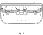
- Fig. 2 shows a sectional view of a locking apparatus 1 of the present utility model.
- the upper coil 50 (second coil half body) comprises a locking apparatus 1 and a coil body 2.
- the locking apparatus 1 comprises an engagement plate 10, a support 20, a shaft 30 and a return spring 40.
- the engagement plate 10 is a substantially plate-like component, disposed on the coil body 2.
- a hook part 11 for engaging with a lower coil 60 (first coil half body) described later is disposed on an end side (in a circumferential direction of the upper coil 50) of the engagement plate; in addition, support parts 12 for supporting the shaft 30 described later are disposed at two ends (in an axial direction of the upper coil 50) of the engagement plate 10 (see fig. 3 ).
- the cradle 20 has support seats 21 disposed in a substantially central part and used for locating the return spring 40, and shaft holes 22 disposed at two ends and used for supporting the shaft 30.
- the return spring 40 is a coil spring; when assembly is carried out, first of all the return spring 40 is located between the two support seats 21 of the cradle 20, and the shaft 30 is passed through the shaft holes 22, the support seats 21 and the return spring 40, and the cradle 20 is fixed to the coil body using screws etc., thereby fitting the locking apparatus 1 to the upper coil 50.
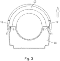
- Fig. 3 shows a drawing of the state of the upper coil 50 and lower coil 60 after being connected together.
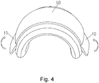
- Fig. 4 shows a three-dimensional drawing of the upper coil 50 being unlocked.
- a lower end of the engagement plate 10 is turned around the shaft 30 thereof, such that the hook part 11 of the engagement plate 10 is separated from the protruding edge 61 of the lower coil 60, and the upper coil 50 can then be separated from the lower coil 60 in an upward direction (in the direction of the arrow shown in fig. 3 ).
- the direction in which force is applied to the locking apparatus 1 of the upper coil 50 during unlocking is the same as the direction of separation of the upper coil 50 after unlocking (the direction of the arrow in fig. 3 ), so it is possible to complete the operation of removing the upper coil at the same time as unlocking is performed, thereby increasing the operating efficiency of the coil.
- Fig. 5 shows a main view of the upper coil 50 to which the locking apparatus 1 has been fitted, after being removed from the lower coil 60 (see fig. 3 ).
- the engagement plate 10 of the locking apparatus 1 is set so that a peripheral surface thereof and a peripheral surface of the upper coil 50 are the same peripheral surface.
- the engagement plates 10 of the locking apparatus 1 remain in a locking position under the action of the return spring 40; compared with the connectors 51 of the upper coil 50 protruding to the outside of the coil, the engagement plates 10 project further in the direction of protrusion.
- the engagement plates 10 remain in a locking position under the action of the return spring 40, and since the engagement plates 10 project further than the connectors 51 in the direction of protrusion thereof (the lower side of fig. 5 ), the engagement plates 10 are in contact with a surface of a supporting object such as a table, so there is no longer any need to provide additional protecting components, as in the past, to protect the connectors 51, and direct contact between the connectors 51 and the surface of the supporting object, resulting in damage to the connectors 51, can be avoided.
- the return spring 40 is used to keep the engagement plate 10 in a locking position, but this is not a limitation; it is only necessary to enable the engagement plates 10 to project in the direction of protrusion of the connectors 51, by a distance greater that the protruding length of the connectors 51, e.g. a limiting component determining the position of the engagement plate 10 after unlocking may be provided.
- a knee coil has been shown by way of example in the embodiments above, with the upper coil 50 thereof separating the coil body and connectors from the lower coil 60 in an upward direction, but the present invention is not limited to a knee coil, and could also be a spine coil, etc.
- a spine coil When used for a spine coil, one coil half body is separated from another coil half body in a horizontal direction parallel to a patient table, in which case the direction of unlocking of the engagement plate is also a horizontal direction.
Landscapes
- Physics & Mathematics (AREA)
- Condensed Matter Physics & Semiconductors (AREA)
- General Physics & Mathematics (AREA)
- Magnetic Resonance Imaging Apparatus (AREA)
- Telephone Set Structure (AREA)
- Details Of Connecting Devices For Male And Female Coupling (AREA)
Abstract
Description
- The present utility model relates to a local coil.
- At present, a local coil e.g. a knee coil comprises two parts, namely an upper coil and a lower coil; when a magnetic resonance scan is carried out, it is necessary for the upper coil and the lower coil to be connected to each other by means of an electrical connector, and locked by a locking apparatus. However, when a locking apparatus of an existing local coil is unlocked, two unlocking buttons disposed on two end sides of the upper coil are pressed towards a radially inner side, but after unlocking, the upper coil is moved in a direction perpendicular to the radial direction and thereby detached from the lower coil. Thus, from the operator's point of view, the force used to achieve unlocking is not in the same direction as the movement of removing the upper coil, therefore the operation is inconvenient for the operator, and this is not helpful with regard to increasing the operating efficiency when the upper and lower halves of the local coil are frequently disassembled. In addition, since metal connectors used for connecting to the lower coil and exposed on the outside of the upper coil are disposed at the position of contact between the upper coil and the lower coil, a separate protecting element must be additionally provided so that, once the upper coil has been removed, the metal connectors are not damaged when the upper coil is placed on its own.
- In view of the above, the present utility model proposes a local coil which uses a simple structure to increase the disassembly efficiency of the local coil and does not need an electrical connector protecting apparatus to be separately provided.
- An embodiment of the present utility model provides a local coil, comprising: a first coil half body; a second coil half body, provided with an electrical connector protruding towards the first coil half body, and being electrically connectable to the first coil half body by means of the electrical connector, the second coil half body being separable from the first coil half body together with the electrical connector in a first direction; a locking apparatus, comprising an engagement plate shaft-supported on the second coil half body, one end of the engagement plate being engagable with the first coil half body in a locking position, and one end of the engagement plate being turnable in the same direction as the first direction so as to move to an unlocking position in which the engagement is released, and in a state in which the first coil half body and the second coil half body have been separated, the locking apparatus can remain in a position in which the locking apparatus projects further than the electrical connector in a direction of protrusion of the electrical connector.
- In addition, in the local coil described above, preferably, the locking apparatus comprises a return spring, the return spring being set so as to always apply a force to the engagement plate towards the locking position, and in a state in which the first coil half body and the second coil half body have been separated, the engagement plate remains in the locking position, and projects further than the electrical connector in the direction of protrusion.
- In addition, in the local coil described above, preferably, a peripheral surface of the locking apparatus is set so as to remain as the same peripheral surface as a peripheral surface of the second coil half body.
- The technical solution according to the present utility model can use a simple structure to realize a local coil which has an increased local coil disassembly efficiency and does not need an electrical connector protecting apparatus to be separately provided.
- Preferred embodiments of the present utility model are described in detail below with reference to the accompanying drawings, to give those skilled in the art a clearer understanding of the abovementioned and other features and advantages of the present utility model.
- Drawings:
-
Fig. 1 shows an exploded three-dimensional drawing of an upper coil to which an embodiment of the present utility model relates. -
Fig. 2 shows a sectional view of a locking apparatus of the present utility model. -
Fig. 3 is a drawing showing the state of the upper coil and a lower coil after being connected together. -
Fig. 4 is an illustrative drawing showing the unlocking of the upper coil. -
Fig. 5 shows a main view of the upper coil to which the locking apparatus has been fitted, after being removed from the lower coil. -
- 1 locking apparatus;
- 2 coil body;
- 10 engagement plate;
- 11 hook part;
- 20 support;
- 30 shaft;
- 40 return spring;
- 50 upper coil;
- 60 lower coil;
- 61 protruding edge
- In order to clarify the object, technical solution and advantages of the present utility model, the present utility model is explained in further detail below by way of embodiments.
- As used herein, "schematic" means "serving as an instance, example or illustration". No drawing or embodiment described herein as "schematic" should be interpreted as a more preferred or more advantageous technical solution.
- To make the drawings appear uncluttered, only those parts relevant to the present utility model are shown schematically in the drawings; they do not represent the actual structure thereof as a product. Furthermore, to make the drawings appear uncluttered for ease of understanding, in the case of components having the same structure or function in certain drawings, only one of these is drawn schematically, or only one is marked.
- Preferred embodiments of the present utility model are explained below with reference to the accompanying drawings. In this embodiment, an explanation is given taking a knee coil as an example.
Fig. 1 shows an exploded three-dimensional drawing of anupper coil 50 to which an embodiment of the present utility model relates.Fig. 2 shows a sectional view of alocking apparatus 1 of the present utility model. - As shown in
figs. 1 and2 , the upper coil 50 (second coil half body) comprises alocking apparatus 1 and a coil body 2. Thelocking apparatus 1 comprises anengagement plate 10, asupport 20, ashaft 30 and areturn spring 40. Theengagement plate 10 is a substantially plate-like component, disposed on the coil body 2. In the state of being disposed on the coil body 2, ahook part 11 for engaging with a lower coil 60 (first coil half body) described later is disposed on an end side (in a circumferential direction of the upper coil 50) of the engagement plate; in addition, supportparts 12 for supporting theshaft 30 described later are disposed at two ends (in an axial direction of the upper coil 50) of the engagement plate 10 (seefig. 3 ). Thecradle 20 has support seats 21 disposed in a substantially central part and used for locating thereturn spring 40, andshaft holes 22 disposed at two ends and used for supporting theshaft 30. Thereturn spring 40 is a coil spring; when assembly is carried out, first of all thereturn spring 40 is located between the two support seats 21 of thecradle 20, and theshaft 30 is passed through theshaft holes 22, the support seats 21 and thereturn spring 40, and thecradle 20 is fixed to the coil body using screws etc., thereby fitting thelocking apparatus 1 to theupper coil 50. -
Fig. 3 shows a drawing of the state of theupper coil 50 andlower coil 60 after being connected together.Fig. 4 shows a three-dimensional drawing of theupper coil 50 being unlocked. - As shown in
fig. 3 , when a local coil is used for scanning, aconnector 51 of theupper coil 50 is inserted into an insertion hole (not shown) of thelower coil 60, thereby realizing the electrical connection of theupper coil 50 to thelower coil 60. At the same time, theengagement plate 10 of thelocking apparatus 1 rotates around theshaft 30 under the action of thereturn spring 40, thereby causing thehook part 11 to automatically engage with aprotruding edge 61 of thelower coil 60, and thereby locking theupper coil 50 to thelower coil 60. When the scan has ended, as shown infig. 4 , theengagement plates 10 are pulled up in the direction of the arrows infig. 4 . At this time, a lower end of theengagement plate 10 is turned around theshaft 30 thereof, such that thehook part 11 of theengagement plate 10 is separated from theprotruding edge 61 of thelower coil 60, and theupper coil 50 can then be separated from thelower coil 60 in an upward direction (in the direction of the arrow shown infig. 3 ). According to an embodiment of the present utility model, the direction in which force is applied to thelocking apparatus 1 of theupper coil 50 during unlocking (the direction of the arrows infig. 4 ) is the same as the direction of separation of theupper coil 50 after unlocking (the direction of the arrow infig. 3 ), so it is possible to complete the operation of removing the upper coil at the same time as unlocking is performed, thereby increasing the operating efficiency of the coil. -
Fig. 5 shows a main view of theupper coil 50 to which thelocking apparatus 1 has been fitted, after being removed from the lower coil 60 (seefig. 3 ). - As shown in
fig. 5 , theengagement plate 10 of thelocking apparatus 1 is set so that a peripheral surface thereof and a peripheral surface of theupper coil 50 are the same peripheral surface. When theupper coil 50 has been removed from the lower coil 60 (seefig. 3 ), theengagement plates 10 of thelocking apparatus 1 remain in a locking position under the action of thereturn spring 40; compared with theconnectors 51 of theupper coil 50 protruding to the outside of the coil, theengagement plates 10 project further in the direction of protrusion. Thus, when theupper coil 50 is removed from thelower coil 60 and placed on a table, theengagement plates 10 remain in a locking position under the action of thereturn spring 40, and since theengagement plates 10 project further than theconnectors 51 in the direction of protrusion thereof (the lower side offig. 5 ), theengagement plates 10 are in contact with a surface of a supporting object such as a table, so there is no longer any need to provide additional protecting components, as in the past, to protect theconnectors 51, and direct contact between theconnectors 51 and the surface of the supporting object, resulting in damage to theconnectors 51, can be avoided. - In the embodiments above, once the
upper coil 50 and thelower coil 60 have been separated, thereturn spring 40 is used to keep theengagement plate 10 in a locking position, but this is not a limitation; it is only necessary to enable theengagement plates 10 to project in the direction of protrusion of theconnectors 51, by a distance greater that the protruding length of theconnectors 51, e.g. a limiting component determining the position of theengagement plate 10 after unlocking may be provided. - In addition, a knee coil has been shown by way of example in the embodiments above, with the
upper coil 50 thereof separating the coil body and connectors from thelower coil 60 in an upward direction, but the present invention is not limited to a knee coil, and could also be a spine coil, etc. When used for a spine coil, one coil half body is separated from another coil half body in a horizontal direction parallel to a patient table, in which case the direction of unlocking of the engagement plate is also a horizontal direction. - The embodiments above are merely preferred embodiments of the present utility model, which are not intended to limit it. Any amendments, equivalent substitutions or improvements etc. made within the spirit and principles of the present utility model shall be included in the scope of protection thereof.
Claims (3)
- A local coil, characterized by
comprising: a first coil half body;
a second coil half body, provided with an electrical connector protruding towards the first coil half body, and being electrically connectable to the first coil half body by means of the electrical connector, the second coil half body being separable from the first coil half body together with the electrical connector in a first direction;
a locking apparatus, comprising an engagement plate shaft-supported on the second coil half body, one end of the engagement plate being engagable with the first coil half body in a locking position, and one end of the engagement plate being turnable in the same direction as the first direction so as to move to an unlocking position in which the engagement is released,
and in a state in which the first coil half body and the second coil half body have been separated, the locking apparatus can remain in a position in which the locking apparatus projects further than the electrical connector in a direction of protrusion of the electrical connector. - The local coil as claimed in claim 1, characterized in that the locking apparatus comprises a return spring, the return spring being set so as to always apply a force to the engagement plate towards the locking position, and in a state in which the first coil half body and the second coil half body have been separated, the engagement plate remains in the locking position, and projects further than the electrical connector in the direction of protrusion.
- The local coil as claimed in claim 1, characterized in that a peripheral surface of the locking apparatus is set so as to remain as the same peripheral surface as a peripheral surface of the second coil half body.
Applications Claiming Priority (1)
| Application Number | Priority Date | Filing Date | Title |
|---|---|---|---|
| CN201720291118.3U CN206638798U (en) | 2017-03-21 | 2017-03-21 | Local coil |
Publications (2)
| Publication Number | Publication Date |
|---|---|
| EP3379280A1 true EP3379280A1 (en) | 2018-09-26 |
| EP3379280B1 EP3379280B1 (en) | 2023-08-23 |
Family
ID=60250664
Family Applications (1)
| Application Number | Title | Priority Date | Filing Date |
|---|---|---|---|
| EP18162559.1A Active EP3379280B1 (en) | 2017-03-21 | 2018-03-19 | Splittable rf coil |
Country Status (2)
| Country | Link |
|---|---|
| EP (1) | EP3379280B1 (en) |
| CN (1) | CN206638798U (en) |
Cited By (1)
| Publication number | Priority date | Publication date | Assignee | Title |
|---|---|---|---|---|
| US11686794B2 (en) | 2020-10-09 | 2023-06-27 | Shanghai United Imaging Healthcare Co., Ltd. | Coil assembly and control method thereof |
Families Citing this family (1)
| Publication number | Priority date | Publication date | Assignee | Title |
|---|---|---|---|---|
| CN115248409B (en) * | 2021-04-27 | 2025-03-25 | 上海联影医疗科技股份有限公司 | Locking structure and magnetic resonance coil device |
Citations (2)
| Publication number | Priority date | Publication date | Assignee | Title |
|---|---|---|---|---|
| JPH06254068A (en) * | 1993-03-03 | 1994-09-13 | Toshiba Corp | Magnetic resonance imaging equipment |
| JP3128263B2 (en) * | 1991-06-03 | 2001-01-29 | 株式会社東芝 | RF coil for magnetic resonance imaging equipment |
-
2017
- 2017-03-21 CN CN201720291118.3U patent/CN206638798U/en active Active
-
2018
- 2018-03-19 EP EP18162559.1A patent/EP3379280B1/en active Active
Patent Citations (2)
| Publication number | Priority date | Publication date | Assignee | Title |
|---|---|---|---|---|
| JP3128263B2 (en) * | 1991-06-03 | 2001-01-29 | 株式会社東芝 | RF coil for magnetic resonance imaging equipment |
| JPH06254068A (en) * | 1993-03-03 | 1994-09-13 | Toshiba Corp | Magnetic resonance imaging equipment |
Cited By (1)
| Publication number | Priority date | Publication date | Assignee | Title |
|---|---|---|---|---|
| US11686794B2 (en) | 2020-10-09 | 2023-06-27 | Shanghai United Imaging Healthcare Co., Ltd. | Coil assembly and control method thereof |
Also Published As
| Publication number | Publication date |
|---|---|
| CN206638798U (en) | 2017-11-14 |
| EP3379280B1 (en) | 2023-08-23 |
Similar Documents
| Publication | Publication Date | Title |
|---|---|---|
| US8205847B2 (en) | Connection system for mounting a device onto a support arm | |
| US3903576A (en) | Apparatus for extracting circuit cards from chassis | |
| KR20160049491A (en) | Cpa device for direct mating and unmating | |
| EP3379280B1 (en) | Splittable rf coil | |
| US8092246B1 (en) | Self-locking micro-D connector | |
| US6923685B2 (en) | Handle locking system for electrical connectors and methods thereof | |
| US8529283B1 (en) | Universal serial bus (USB) connector having positive retention | |
| US10367298B2 (en) | Electrical connector | |
| CN104358981B (en) | A kind of support of electronic product connecting base and band connection base | |
| US20130263444A1 (en) | Clamping apparatus for removing connector | |
| JP2018521750A5 (en) | ||
| US20150011106A1 (en) | Lever Type Connector | |
| CN114641413A (en) | Driver Airbag Module Connection Assembly | |
| CN105514727B (en) | A kind of connect-disconnect structure of connector | |
| US7195510B2 (en) | Electrical connector systems with latching assemblies and methods thereof | |
| JP6334672B2 (en) | Latch connector assembly | |
| US20160093973A1 (en) | Connector coupling structure | |
| KR20160003976U (en) | Lockable socket | |
| US20150333443A1 (en) | Latch assemblies for connector systems | |
| CN105379027B (en) | locking device for plug-in connector | |
| CN208352626U (en) | Cable connector docking structure | |
| CN205811166U (en) | A kind of compact self-locking jack contact assembly and electric connector | |
| JP7057241B2 (en) | Terminal connection mechanism | |
| CN209949322U (en) | Card lock mechanism, pluggable module and communication equipment | |
| CN105262865B (en) | Fastening structure and protective shell with same |
Legal Events
| Date | Code | Title | Description |
|---|---|---|---|
| PUAI | Public reference made under article 153(3) epc to a published international application that has entered the european phase |
Free format text: ORIGINAL CODE: 0009012 |
|
| STAA | Information on the status of an ep patent application or granted ep patent |
Free format text: STATUS: REQUEST FOR EXAMINATION WAS MADE |
|
| 17P | Request for examination filed |
Effective date: 20180319 |
|
| AK | Designated contracting states |
Kind code of ref document: A1 Designated state(s): AL AT BE BG CH CY CZ DE DK EE ES FI FR GB GR HR HU IE IS IT LI LT LU LV MC MK MT NL NO PL PT RO RS SE SI SK SM TR |
|
| AX | Request for extension of the european patent |
Extension state: BA ME |
|
| RBV | Designated contracting states (corrected) |
Designated state(s): AL AT BE BG CH CY CZ DE DK EE ES FI FR GB GR HR HU IE IS IT LI LT LU LV MC MK MT NL NO PL PT RO RS SE SI SK SM TR |
|
| STAA | Information on the status of an ep patent application or granted ep patent |
Free format text: STATUS: EXAMINATION IS IN PROGRESS |
|
| 17Q | First examination report despatched |
Effective date: 20210510 |
|
| GRAP | Despatch of communication of intention to grant a patent |
Free format text: ORIGINAL CODE: EPIDOSNIGR1 |
|
| STAA | Information on the status of an ep patent application or granted ep patent |
Free format text: STATUS: GRANT OF PATENT IS INTENDED |
|
| INTG | Intention to grant announced |
Effective date: 20230404 |
|
| GRAS | Grant fee paid |
Free format text: ORIGINAL CODE: EPIDOSNIGR3 |
|
| GRAA | (expected) grant |
Free format text: ORIGINAL CODE: 0009210 |
|
| STAA | Information on the status of an ep patent application or granted ep patent |
Free format text: STATUS: THE PATENT HAS BEEN GRANTED |
|
| AK | Designated contracting states |
Kind code of ref document: B1 Designated state(s): AL AT BE BG CH CY CZ DE DK EE ES FI FR GB GR HR HU IE IS IT LI LT LU LV MC MK MT NL NO PL PT RO RS SE SI SK SM TR |
|
| REG | Reference to a national code |
Ref country code: GB Ref legal event code: FG4D |
|
| REG | Reference to a national code |
Ref country code: CH Ref legal event code: EP |
|
| REG | Reference to a national code |
Ref country code: IE Ref legal event code: FG4D |
|
| REG | Reference to a national code |
Ref country code: DE Ref legal event code: R096 Ref document number: 602018055787 Country of ref document: DE |
|
| REG | Reference to a national code |
Ref country code: LT Ref legal event code: MG9D |
|
| REG | Reference to a national code |
Ref country code: NL Ref legal event code: MP Effective date: 20230823 |
|
| REG | Reference to a national code |
Ref country code: AT Ref legal event code: MK05 Ref document number: 1603218 Country of ref document: AT Kind code of ref document: T Effective date: 20230823 |
|
| PG25 | Lapsed in a contracting state [announced via postgrant information from national office to epo] |
Ref country code: GR Free format text: LAPSE BECAUSE OF FAILURE TO SUBMIT A TRANSLATION OF THE DESCRIPTION OR TO PAY THE FEE WITHIN THE PRESCRIBED TIME-LIMIT Effective date: 20231124 |
|
| PG25 | Lapsed in a contracting state [announced via postgrant information from national office to epo] |
Ref country code: IS Free format text: LAPSE BECAUSE OF FAILURE TO SUBMIT A TRANSLATION OF THE DESCRIPTION OR TO PAY THE FEE WITHIN THE PRESCRIBED TIME-LIMIT Effective date: 20231223 |
|
| PG25 | Lapsed in a contracting state [announced via postgrant information from national office to epo] |
Ref country code: SE Free format text: LAPSE BECAUSE OF FAILURE TO SUBMIT A TRANSLATION OF THE DESCRIPTION OR TO PAY THE FEE WITHIN THE PRESCRIBED TIME-LIMIT Effective date: 20230823 Ref country code: RS Free format text: LAPSE BECAUSE OF FAILURE TO SUBMIT A TRANSLATION OF THE DESCRIPTION OR TO PAY THE FEE WITHIN THE PRESCRIBED TIME-LIMIT Effective date: 20230823 Ref country code: PT Free format text: LAPSE BECAUSE OF FAILURE TO SUBMIT A TRANSLATION OF THE DESCRIPTION OR TO PAY THE FEE WITHIN THE PRESCRIBED TIME-LIMIT Effective date: 20231226 Ref country code: NO Free format text: LAPSE BECAUSE OF FAILURE TO SUBMIT A TRANSLATION OF THE DESCRIPTION OR TO PAY THE FEE WITHIN THE PRESCRIBED TIME-LIMIT Effective date: 20231123 Ref country code: NL Free format text: LAPSE BECAUSE OF FAILURE TO SUBMIT A TRANSLATION OF THE DESCRIPTION OR TO PAY THE FEE WITHIN THE PRESCRIBED TIME-LIMIT Effective date: 20230823 Ref country code: LV Free format text: LAPSE BECAUSE OF FAILURE TO SUBMIT A TRANSLATION OF THE DESCRIPTION OR TO PAY THE FEE WITHIN THE PRESCRIBED TIME-LIMIT Effective date: 20230823 Ref country code: LT Free format text: LAPSE BECAUSE OF FAILURE TO SUBMIT A TRANSLATION OF THE DESCRIPTION OR TO PAY THE FEE WITHIN THE PRESCRIBED TIME-LIMIT Effective date: 20230823 Ref country code: IS Free format text: LAPSE BECAUSE OF FAILURE TO SUBMIT A TRANSLATION OF THE DESCRIPTION OR TO PAY THE FEE WITHIN THE PRESCRIBED TIME-LIMIT Effective date: 20231223 Ref country code: HR Free format text: LAPSE BECAUSE OF FAILURE TO SUBMIT A TRANSLATION OF THE DESCRIPTION OR TO PAY THE FEE WITHIN THE PRESCRIBED TIME-LIMIT Effective date: 20230823 Ref country code: GR Free format text: LAPSE BECAUSE OF FAILURE TO SUBMIT A TRANSLATION OF THE DESCRIPTION OR TO PAY THE FEE WITHIN THE PRESCRIBED TIME-LIMIT Effective date: 20231124 Ref country code: FI Free format text: LAPSE BECAUSE OF FAILURE TO SUBMIT A TRANSLATION OF THE DESCRIPTION OR TO PAY THE FEE WITHIN THE PRESCRIBED TIME-LIMIT Effective date: 20230823 Ref country code: AT Free format text: LAPSE BECAUSE OF FAILURE TO SUBMIT A TRANSLATION OF THE DESCRIPTION OR TO PAY THE FEE WITHIN THE PRESCRIBED TIME-LIMIT Effective date: 20230823 |
|
| RAP2 | Party data changed (patent owner data changed or rights of a patent transferred) |
Owner name: SIEMENS HEALTHINEERS AG |
|
| REG | Reference to a national code |
Ref country code: DE Ref legal event code: R081 Ref document number: 602018055787 Country of ref document: DE Owner name: SIEMENS HEALTHINEERS AG, DE Free format text: FORMER OWNER: SIEMENS HEALTHCARE GMBH, MUENCHEN, DE |
|
| PG25 | Lapsed in a contracting state [announced via postgrant information from national office to epo] |
Ref country code: PL Free format text: LAPSE BECAUSE OF FAILURE TO SUBMIT A TRANSLATION OF THE DESCRIPTION OR TO PAY THE FEE WITHIN THE PRESCRIBED TIME-LIMIT Effective date: 20230823 |
|
| PG25 | Lapsed in a contracting state [announced via postgrant information from national office to epo] |
Ref country code: ES Free format text: LAPSE BECAUSE OF FAILURE TO SUBMIT A TRANSLATION OF THE DESCRIPTION OR TO PAY THE FEE WITHIN THE PRESCRIBED TIME-LIMIT Effective date: 20230823 |
|
| PG25 | Lapsed in a contracting state [announced via postgrant information from national office to epo] |
Ref country code: SM Free format text: LAPSE BECAUSE OF FAILURE TO SUBMIT A TRANSLATION OF THE DESCRIPTION OR TO PAY THE FEE WITHIN THE PRESCRIBED TIME-LIMIT Effective date: 20230823 Ref country code: RO Free format text: LAPSE BECAUSE OF FAILURE TO SUBMIT A TRANSLATION OF THE DESCRIPTION OR TO PAY THE FEE WITHIN THE PRESCRIBED TIME-LIMIT Effective date: 20230823 Ref country code: ES Free format text: LAPSE BECAUSE OF FAILURE TO SUBMIT A TRANSLATION OF THE DESCRIPTION OR TO PAY THE FEE WITHIN THE PRESCRIBED TIME-LIMIT Effective date: 20230823 Ref country code: EE Free format text: LAPSE BECAUSE OF FAILURE TO SUBMIT A TRANSLATION OF THE DESCRIPTION OR TO PAY THE FEE WITHIN THE PRESCRIBED TIME-LIMIT Effective date: 20230823 Ref country code: DK Free format text: LAPSE BECAUSE OF FAILURE TO SUBMIT A TRANSLATION OF THE DESCRIPTION OR TO PAY THE FEE WITHIN THE PRESCRIBED TIME-LIMIT Effective date: 20230823 Ref country code: CZ Free format text: LAPSE BECAUSE OF FAILURE TO SUBMIT A TRANSLATION OF THE DESCRIPTION OR TO PAY THE FEE WITHIN THE PRESCRIBED TIME-LIMIT Effective date: 20230823 Ref country code: SK Free format text: LAPSE BECAUSE OF FAILURE TO SUBMIT A TRANSLATION OF THE DESCRIPTION OR TO PAY THE FEE WITHIN THE PRESCRIBED TIME-LIMIT Effective date: 20230823 |
|
| REG | Reference to a national code |
Ref country code: DE Ref legal event code: R097 Ref document number: 602018055787 Country of ref document: DE |
|
| PG25 | Lapsed in a contracting state [announced via postgrant information from national office to epo] |
Ref country code: IT Free format text: LAPSE BECAUSE OF FAILURE TO SUBMIT A TRANSLATION OF THE DESCRIPTION OR TO PAY THE FEE WITHIN THE PRESCRIBED TIME-LIMIT Effective date: 20230823 |
|
| PLBE | No opposition filed within time limit |
Free format text: ORIGINAL CODE: 0009261 |
|
| STAA | Information on the status of an ep patent application or granted ep patent |
Free format text: STATUS: NO OPPOSITION FILED WITHIN TIME LIMIT |
|
| 26N | No opposition filed |
Effective date: 20240524 |
|
| PG25 | Lapsed in a contracting state [announced via postgrant information from national office to epo] |
Ref country code: SI Free format text: LAPSE BECAUSE OF FAILURE TO SUBMIT A TRANSLATION OF THE DESCRIPTION OR TO PAY THE FEE WITHIN THE PRESCRIBED TIME-LIMIT Effective date: 20230823 |
|
| REG | Reference to a national code |
Ref country code: CH Ref legal event code: PL |
|
| PG25 | Lapsed in a contracting state [announced via postgrant information from national office to epo] |
Ref country code: BG Free format text: LAPSE BECAUSE OF FAILURE TO SUBMIT A TRANSLATION OF THE DESCRIPTION OR TO PAY THE FEE WITHIN THE PRESCRIBED TIME-LIMIT Effective date: 20230823 |
|
| PG25 | Lapsed in a contracting state [announced via postgrant information from national office to epo] |
Ref country code: LU Free format text: LAPSE BECAUSE OF NON-PAYMENT OF DUE FEES Effective date: 20240319 |
|
| PG25 | Lapsed in a contracting state [announced via postgrant information from national office to epo] |
Ref country code: MC Free format text: LAPSE BECAUSE OF FAILURE TO SUBMIT A TRANSLATION OF THE DESCRIPTION OR TO PAY THE FEE WITHIN THE PRESCRIBED TIME-LIMIT Effective date: 20230823 |
|
| PG25 | Lapsed in a contracting state [announced via postgrant information from national office to epo] |
Ref country code: MC Free format text: LAPSE BECAUSE OF FAILURE TO SUBMIT A TRANSLATION OF THE DESCRIPTION OR TO PAY THE FEE WITHIN THE PRESCRIBED TIME-LIMIT Effective date: 20230823 Ref country code: LU Free format text: LAPSE BECAUSE OF NON-PAYMENT OF DUE FEES Effective date: 20240319 Ref country code: BG Free format text: LAPSE BECAUSE OF FAILURE TO SUBMIT A TRANSLATION OF THE DESCRIPTION OR TO PAY THE FEE WITHIN THE PRESCRIBED TIME-LIMIT Effective date: 20230823 |
|
| REG | Reference to a national code |
Ref country code: BE Ref legal event code: MM Effective date: 20240331 |
|
| PG25 | Lapsed in a contracting state [announced via postgrant information from national office to epo] |
Ref country code: BE Free format text: LAPSE BECAUSE OF NON-PAYMENT OF DUE FEES Effective date: 20240331 |
|
| PG25 | Lapsed in a contracting state [announced via postgrant information from national office to epo] |
Ref country code: FR Free format text: LAPSE BECAUSE OF NON-PAYMENT OF DUE FEES Effective date: 20240331 |
|
| PG25 | Lapsed in a contracting state [announced via postgrant information from national office to epo] |
Ref country code: IE Free format text: LAPSE BECAUSE OF NON-PAYMENT OF DUE FEES Effective date: 20240319 |
|
| PG25 | Lapsed in a contracting state [announced via postgrant information from national office to epo] |
Ref country code: IE Free format text: LAPSE BECAUSE OF NON-PAYMENT OF DUE FEES Effective date: 20240319 Ref country code: FR Free format text: LAPSE BECAUSE OF NON-PAYMENT OF DUE FEES Effective date: 20240331 Ref country code: BE Free format text: LAPSE BECAUSE OF NON-PAYMENT OF DUE FEES Effective date: 20240331 Ref country code: CH Free format text: LAPSE BECAUSE OF NON-PAYMENT OF DUE FEES Effective date: 20240331 |
|
| PGFP | Annual fee paid to national office [announced via postgrant information from national office to epo] |
Ref country code: DE Payment date: 20250520 Year of fee payment: 8 |
|
| PGFP | Annual fee paid to national office [announced via postgrant information from national office to epo] |
Ref country code: GB Payment date: 20250403 Year of fee payment: 8 |
|
| PG25 | Lapsed in a contracting state [announced via postgrant information from national office to epo] |
Ref country code: CY Free format text: LAPSE BECAUSE OF FAILURE TO SUBMIT A TRANSLATION OF THE DESCRIPTION OR TO PAY THE FEE WITHIN THE PRESCRIBED TIME-LIMIT; INVALID AB INITIO Effective date: 20180319 |
|
| PG25 | Lapsed in a contracting state [announced via postgrant information from national office to epo] |
Ref country code: HU Free format text: LAPSE BECAUSE OF FAILURE TO SUBMIT A TRANSLATION OF THE DESCRIPTION OR TO PAY THE FEE WITHIN THE PRESCRIBED TIME-LIMIT; INVALID AB INITIO Effective date: 20180319 |
|
| PG25 | Lapsed in a contracting state [announced via postgrant information from national office to epo] |
Ref country code: TR Free format text: LAPSE BECAUSE OF FAILURE TO SUBMIT A TRANSLATION OF THE DESCRIPTION OR TO PAY THE FEE WITHIN THE PRESCRIBED TIME-LIMIT Effective date: 20230823 |