EP3379259A1 - Vertical wind sensing system - Google Patents
Vertical wind sensing system Download PDFInfo
- Publication number
- EP3379259A1 EP3379259A1 EP17162864.7A EP17162864A EP3379259A1 EP 3379259 A1 EP3379259 A1 EP 3379259A1 EP 17162864 A EP17162864 A EP 17162864A EP 3379259 A1 EP3379259 A1 EP 3379259A1
- Authority
- EP
- European Patent Office
- Prior art keywords
- aircraft
- angle
- attack
- sensor system
- vertical wind
- Prior art date
- Legal status (The legal status is an assumption and is not a legal conclusion. Google has not performed a legal analysis and makes no representation as to the accuracy of the status listed.)
- Withdrawn
Links
- 238000000034 method Methods 0.000 claims abstract description 20
- 239000000523 sample Substances 0.000 claims description 16
- 230000002349 favourable effect Effects 0.000 abstract description 6
- 239000003570 air Substances 0.000 description 26
- 238000012417 linear regression Methods 0.000 description 5
- 238000005259 measurement Methods 0.000 description 3
- 238000012935 Averaging Methods 0.000 description 1
- 239000012080 ambient air Substances 0.000 description 1
- 238000004458 analytical method Methods 0.000 description 1
- 238000004364 calculation method Methods 0.000 description 1
- 238000010586 diagram Methods 0.000 description 1
- 239000000446 fuel Substances 0.000 description 1
- 238000012986 modification Methods 0.000 description 1
- 230000004048 modification Effects 0.000 description 1
- 238000011160 research Methods 0.000 description 1
- 230000003068 static effect Effects 0.000 description 1
Images
Classifications
-
- G—PHYSICS
- G01—MEASURING; TESTING
- G01P—MEASURING LINEAR OR ANGULAR SPEED, ACCELERATION, DECELERATION, OR SHOCK; INDICATING PRESENCE, ABSENCE, OR DIRECTION, OF MOVEMENT
- G01P5/00—Measuring speed of fluids, e.g. of air stream; Measuring speed of bodies relative to fluids, e.g. of ship, of aircraft
- G01P5/14—Measuring speed of fluids, e.g. of air stream; Measuring speed of bodies relative to fluids, e.g. of ship, of aircraft by measuring differences of pressure in the fluid
- G01P5/16—Measuring speed of fluids, e.g. of air stream; Measuring speed of bodies relative to fluids, e.g. of ship, of aircraft by measuring differences of pressure in the fluid using Pitot tubes, e.g. Machmeter
-
- G—PHYSICS
- G01—MEASURING; TESTING
- G01P—MEASURING LINEAR OR ANGULAR SPEED, ACCELERATION, DECELERATION, OR SHOCK; INDICATING PRESENCE, ABSENCE, OR DIRECTION, OF MOVEMENT
- G01P5/00—Measuring speed of fluids, e.g. of air stream; Measuring speed of bodies relative to fluids, e.g. of ship, of aircraft
Definitions
- the present invention relates to a method of determining vertical wind using an aircraft sensor system carried by an aircraft in flight, and an associated vertical wind sensing system or network.
- Aircraft can also be used to measure horizontal winds.
- An example is described in " Airplanes Aloft as a Sensor Network for Wind Forecasting", Kapoor et al, http://research.microsoft.com/en-us/um/people/horvitz/planesenors.pdflink . Winds encountered by aircraft are inferred on the basis of a ground speed observation, and the airspeed as expressed in the flight plan.
- Another example is given in “ Using aircraft as wind sensors for estimating accurate wind fields for air traffic management applications", Guadano et al, http://oa.upm.es/36006/1/INVE_MEM_2014195683.pdf .
- a first aspect of the invention provides a method of determining vertical wind using an aircraft sensor system carried by an aircraft in flight, as set out in claim 1.
- An aircraft sensor system is operated to obtain vertical ground speed, air speed, pitch, and angle of attack. These parameters are then used to determine the vertical wind. Aircraft flying in regions of down wind burn more fuel than aircraft flying in regions of up wind.
- the invention provides a method of measuring vertical wind using an aircraft sensor system, which can then be used by the aircraft, or other aircraft, to optimise their flight paths based on favourable up wind. Alternatively, the vertical wind can be used to analyse drag characteristics of the aircraft or for some other reason.
- the vertical ground speed may be obtained by a global positioning system (GPS) unit.
- GPS global positioning system
- the vertical ground speed is the vertical speed of the aircraft relative to the ground.
- the air speed may be obtained by a pitot-static system, or other air speed measurement system. Typically the air speed is the speed of the aircraft relative to the air. The air speed obtained by the pitot-static system may optionally be corrected to account for the angle of attack of the aircraft.
- the pitch may be obtained by an inertial reference unit such as a gyroscope.
- the pitch is an angle of inclination of a reference line of the aircraft (such as its longitudinal axis) relative to the horizontal.
- the angle of attack may be obtained by an angle of attack probe such as a rotating vane.
- the angle of attack is the angle between a reference line of the aircraft (such as a chord line of its wing) and a vector representing the relative motion between the aircraft and the air.
- vertical wind UZ0 - TAS.sin( ⁇ - ⁇ ), where UZ0 is the vertical ground speed; TAS is the air speed; ⁇ is the pitch; and ⁇ is the angle of attack.
- the method comprises operating an angle of attack (AOA) probe of the aircraft sensor system to obtain the angle of attack of the aircraft.
- AOA angle of attack
- the AOA probe may be a rotating vane, or any other type of AOA probe.
- the angle of attack may be obtained by: operating an angle of attack (AOA) probe of the aircraft sensor system to obtain a directly-measured angle of attack of the aircraft; operating the aircraft sensor system to measure a flight path angle of the aircraft relative to the ground; calculating an estimated angle of attack in accordance with the flight path angle of the aircraft relative to the ground and the pitch; and de-biasing the directly-measured angle of attack of the aircraft in accordance with a difference between the directly-measured angle of attack and the estimated angle of attack.
- the de-biasing may be achieved by averaging the difference over a time period, or by performing multiple linear regressions of the difference.
- the vertical wind may be stored and/or displayed, either on the aircraft or at a ground station.
- a computer carried by the aircraft may be operated to determine the vertical wind in accordance with the flight parameters obtained by the aircraft sensor system.
- the vertical wind may then be transmitted from the aircraft in flight - either to a ground station or directly to another aircraft.
- the aircraft may transmit the flight parameters to a ground station which calculates the vertical wind.
- a second aspect of the invention provides a flight path optimisation method as set out in claim 8, in which a vertical wind determined by a first aircraft in flight is used to optimise a flight path of a second aircraft in flight.
- the second aspect of the invention can be extended to provide a network of connected aircraft which share vertical wind information and optimise their flight paths based on favourable up winds.
- a third aspect of the invention provides a vertical wind sensing system as set out in claim 9.
- An aircraft sensor system is arranged to obtain flight parameters of the aircraft; and a computer is configured to determine the vertical wind in accordance with the flight parameters obtained by the aircraft sensor system.
- the computer may be carried by the aircraft, or it may be at a ground station or another aircraft.
- the computer may be part of a Flight Guidance and Management System (FGMS) carried by the aircraft or an Air Data Inertial Reference System (ADIRS) carried by the aircraft.
- FGMS Flight Guidance and Management System
- ADIRS Air Data Inertial Reference System
- the aircraft sensor system comprises a global positioning system (GPS) unit, arranged to obtain the vertical ground speed of the aircraft.
- GPS global positioning system
- the aircraft sensor system comprises a pitot-static system, or other air speed measurement sensor, arranged to obtain the air speed of the aircraft.
- the aircraft sensor system comprises an inertial reference unit, such as a gyroscope, arranged to obtain the pitch of the aircraft.
- an inertial reference unit such as a gyroscope
- the aircraft sensor system comprises an angle of attack (AOA) probe, such as a rotating vane, arranged to obtain the angle of attack of the aircraft.
- AOA angle of attack
- a fourth aspect of the invention provides a vertical wind sensing network as set out in claim 15, in which a central repository is arranged to receive and collate vertical winds from plural vertical wind sensing systems.
- the central repository which may be located for instance at a meteorological office or airline operations centre, can create a map of vertical winds.
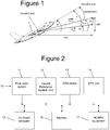
- An aircraft 1 shown in Figure 1 carries an aircraft sensor system 10 shown in Figure 2 .
- the aircraft sensor system 10 comprises various sensors arranged to obtain flight parameters of the aircraft.
- the sensors include a pitot-static sensor system 11 arranged to obtain the air speed of the aircraft; an air data inertial reference unit (ADIRU) 12, such as a gyroscope, arranged to obtain the pitch of the aircraft; an angle of attack (AOA) probe 13 arranged to obtain the angle of attack of the aircraft; and a global positioning system (GPS) unit 14.
- the sensors 11-14 are connected to an on-board computer 15 which may be part of a Flight Guidance and Management System (FGMS) or Air Data Inertial Reference System (ADIRS) installed on the aircraft.
- FGMS Flight Guidance and Management System
- ADIRS Air Data Inertial Reference System
- the pitot-static sensor system 11 comprises one or more pitot-tube sensors which detect ambient air pressure affected by the motion of the aircraft (pitot pressure) and one or more sensors which detect ambient pressure unaffected by the motion of the aircraft (static pressure). The difference between these pressures is then used by the pitot-static sensor system 11 to calculate a true air speed - that is, the speed of the aircraft relative to the air mass in which it is flying.
- the velocity of the aircraft relative to the air is indicated in Figure 1 as a vector V TAS .
- the aircraft has a frame of reference with an X-axis shown in Figure 1 , a Z-axis also shown in Figure 1 , and a Y-axis not shown.
- the vector V TAS has X, Y and Z components V X , V Y , V Z , in this frame of reference.
- the pitot-static sensor system 11 is aligned with the aircraft X-axis, so the true air speed output by the pitot-static sensor system 11 is a scalar quantity V X indicating the X-component only.
- the X-axis of the aircraft has an angle of attack, indicated as ⁇ in Figure 1 , relative to the airflow.
- This angle of attack ⁇ is measured by an angle of attack (AOA) probe 13.
- the AOA probe 13 comprises a vane which is exposed to the airflow so that it rotates about an axis of rotation parallel with the aircraft Y-axis to line up with the airflow. So the angle of the AOA probe 13 gives the angle of attack ⁇ .
- TAS SQRT (V X 2 + V Z 2 )
- the sideslip Vy of the aircraft is assumed to be zero.
- the aircraft X-axis has a pitch ⁇ relative to a horizontal plane, as indicated in Figure 1 .
- the inertial reference system unit 12 measures this angle ⁇ .
- the aircraft has a velocity vector V GND relative to the ground with horizontal components UX0, UY0, and a vertical component UZ0.
- a Global Position System (GPS) unit 14 measures the position of the aircraft relative to the ground, and differentiates the Z-component of this position with respect to time to obtain UZ0.
- GPS Global Position System
- the wind acting on the aircraft has horizontal wind components W x , W y , and a vertical wind component W z which will be referred to below as vertical wind.
- the vertical wind may be stored in a memory 16 on-board the aircraft and/or displayed on the aircraft.
- the aircraft 1 carries various Aircraft Communications Addressing and Reporting System (ACARS) equipment 17 which can transmit and receive data to an ACARS ground station.
- ACARS Aircraft Communications Addressing and Reporting System
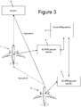
- the network comprises a plurality of aircraft each of which can determine the vertical wind as described above and transmit it to a respective ACARS ground station 3, 4.
- a central repository 5 (at an aircraft operations centre or meteorological office) is arranged to receive and collate the vertical winds received from the aircraft 1, 2 via the ACARS ground stations 3, 4.
- the aircraft 1, 2 periodically transmit vertical wind, latitude, longitude and other relevant information from its aircraft sensor system 10 to the central repository 5 during flight.
- the central repository 5 can then collate the vertical wind information provided by all the aircraft. This will give a view of the 3D wind along the flight paths of multiple aircraft. Interpolation of the 3D wind, together with other forecasts, can create a contiguous and real-time 3D wind map to the airlines.
- the airlines can then adjust flight plans to take into account both favourable horizontal wind (namely, tail winds) and favourable vertical winds (namely, up winds).
- a simplified flight path optimisation method is shown in Figure 3 .
- the first and second aircraft 1, 2 are enroute to an airport 6.
- the second aircraft 2 is following a flight path A.
- a vertical wind is determined by the first aircraft 1 and communicated to the central repository 5. This is communicated to the second aircraft 2 by the central repository 5 via the ACARS ground station 4.
- the vertical wind information from the first aircraft 1 is used by the second aircraft 2 to optimise its flight path. In this case the first aircraft 1 is experiencing an up wind, so the route of the second aircraft 2 is adjusted to follow an alternative flight path B.
- the directly-measured angle of attack ⁇ (measured) output by the AOA probe 13 can be accurate in variations, but inaccurate in absolute terms. In other words ⁇ (measured) has an unknown and relatively constant error.
- the aircraft has a flight path angle ⁇ air relative to the air and a flight path angle ⁇ gnd relative to the ground.
- the flight path angle ⁇ gnd relative to the ground can be measured by the GPS unit 14.
- the angle of attack can be de-biased by the following method:
- the coefficients A1, A2, B1, B2, C1 and C2 are calculated in the following way.
- de-biased angle of attack ⁇ (de-biased) calculated by either of the above methods, can then be introduced into equation (1) to provide a more accurate calculation of the vertical wind.
Landscapes
- Engineering & Computer Science (AREA)
- Aviation & Aerospace Engineering (AREA)
- Physics & Mathematics (AREA)
- General Physics & Mathematics (AREA)
- Traffic Control Systems (AREA)
Abstract
Description
- The present invention relates to a method of determining vertical wind using an aircraft sensor system carried by an aircraft in flight, and an associated vertical wind sensing system or network.
- Meterological agencies measure horizontal winds, and flight paths are optimised to take advantage of favourable horizontal winds (tail winds).
- Aircraft can also be used to measure horizontal winds. An example is described in "Airplanes Aloft as a Sensor Network for Wind Forecasting", Kapoor et al, http://research.microsoft.com/en-us/um/people/horvitz/planesenors.pdflink. Winds encountered by aircraft are inferred on the basis of a ground speed observation, and the airspeed as expressed in the flight plan. Another example is given in "Using aircraft as wind sensors for estimating accurate wind fields for air traffic management applications", Guadano et al, http://oa.upm.es/36006/1/INVE_MEM_2014195683.pdf.
- A first aspect of the invention provides a method of determining vertical wind using an aircraft sensor system carried by an aircraft in flight, as set out in
claim 1. - An aircraft sensor system is operated to obtain vertical ground speed, air speed, pitch, and angle of attack. These parameters are then used to determine the vertical wind. Aircraft flying in regions of down wind burn more fuel than aircraft flying in regions of up wind. The invention provides a method of measuring vertical wind using an aircraft sensor system, which can then be used by the aircraft, or other aircraft, to optimise their flight paths based on favourable up wind. Alternatively, the vertical wind can be used to analyse drag characteristics of the aircraft or for some other reason.
- The vertical ground speed may be obtained by a global positioning system (GPS) unit. Typically the vertical ground speed is the vertical speed of the aircraft relative to the ground.
- The air speed may be obtained by a pitot-static system, or other air speed measurement system. Typically the air speed is the speed of the aircraft relative to the air. The air speed obtained by the pitot-static system may optionally be corrected to account for the angle of attack of the aircraft.
- The pitch may be obtained by an inertial reference unit such as a gyroscope. Typically the pitch is an angle of inclination of a reference line of the aircraft (such as its longitudinal axis) relative to the horizontal.
- The angle of attack may be obtained by an angle of attack probe such as a rotating vane. Typically the angle of attack is the angle between a reference line of the aircraft (such as a chord line of its wing) and a vector representing the relative motion between the aircraft and the air.
- Typically the vertical wind is determined in accordance with the following formula, or a mathematical equivalent: vertical wind = UZ0 - TAS.sin(θ-α), where UZ0 is the vertical ground speed; TAS is the air speed; θ is the pitch; and α is the angle of attack.
- Optionally the method comprises operating an angle of attack (AOA) probe of the aircraft sensor system to obtain the angle of attack of the aircraft. The AOA probe may be a rotating vane, or any other type of AOA probe.
- The angle of attack may be obtained by: operating an angle of attack (AOA) probe of the aircraft sensor system to obtain a directly-measured angle of attack of the aircraft; operating the aircraft sensor system to measure a flight path angle of the aircraft relative to the ground; calculating an estimated angle of attack in accordance with the flight path angle of the aircraft relative to the ground and the pitch; and de-biasing the directly-measured angle of attack of the aircraft in accordance with a difference between the directly-measured angle of attack and the estimated angle of attack. The de-biasing may be achieved by averaging the difference over a time period, or by performing multiple linear regressions of the difference.
- The vertical wind may be stored and/or displayed, either on the aircraft or at a ground station.
- A computer carried by the aircraft may be operated to determine the vertical wind in accordance with the flight parameters obtained by the aircraft sensor system. The vertical wind may then be transmitted from the aircraft in flight - either to a ground station or directly to another aircraft. Alternatively the aircraft may transmit the flight parameters to a ground station which calculates the vertical wind.
- A second aspect of the invention provides a flight path optimisation method as set out in claim 8, in which a vertical wind determined by a first aircraft in flight is used to optimise a flight path of a second aircraft in flight. The second aspect of the invention can be extended to provide a network of connected aircraft which share vertical wind information and optimise their flight paths based on favourable up winds.
- A third aspect of the invention provides a vertical wind sensing system as set out in claim 9. An aircraft sensor system is arranged to obtain flight parameters of the aircraft; and a computer is configured to determine the vertical wind in accordance with the flight parameters obtained by the aircraft sensor system. The computer may be carried by the aircraft, or it may be at a ground station or another aircraft. For example, the computer may be part of a Flight Guidance and Management System (FGMS) carried by the aircraft or an Air Data Inertial Reference System (ADIRS) carried by the aircraft.
- Typically the aircraft sensor system comprises a global positioning system (GPS) unit, arranged to obtain the vertical ground speed of the aircraft.
- Typically the aircraft sensor system comprises a pitot-static system, or other air speed measurement sensor, arranged to obtain the air speed of the aircraft.
- Typically the aircraft sensor system comprises an inertial reference unit, such as a gyroscope, arranged to obtain the pitch of the aircraft.
- Typically the aircraft sensor system comprises an angle of attack (AOA) probe, such as a rotating vane, arranged to obtain the angle of attack of the aircraft.
- A fourth aspect of the invention provides a vertical wind sensing network as set out in
claim 15, in which a central repository is arranged to receive and collate vertical winds from plural vertical wind sensing systems. The central repository, which may be located for instance at a meteorological office or airline operations centre, can create a map of vertical winds. - Embodiments of the invention will now be described with reference to the accompanying drawings, in which:
-
Figure 1 is a side view of an aircraft which forms part of a vertical wind sensing system; -
Figure 2 is a schematic diagram showing an aircraft sensor system and other electronic equipment on-board the aircraft; and -
Figure 3 shows a vertical wind sensing network incorporating the aircraft ofFigure 1 . - An
aircraft 1 shown inFigure 1 carries anaircraft sensor system 10 shown inFigure 2 . Theaircraft sensor system 10 comprises various sensors arranged to obtain flight parameters of the aircraft. The sensors include a pitot-static sensor system 11 arranged to obtain the air speed of the aircraft; an air data inertial reference unit (ADIRU) 12, such as a gyroscope, arranged to obtain the pitch of the aircraft; an angle of attack (AOA)probe 13 arranged to obtain the angle of attack of the aircraft; and a global positioning system (GPS)unit 14. The sensors 11-14 are connected to an on-board computer 15 which may be part of a Flight Guidance and Management System (FGMS) or Air Data Inertial Reference System (ADIRS) installed on the aircraft. - The pitot-
static sensor system 11 comprises one or more pitot-tube sensors which detect ambient air pressure affected by the motion of the aircraft (pitot pressure) and one or more sensors which detect ambient pressure unaffected by the motion of the aircraft (static pressure). The difference between these pressures is then used by the pitot-static sensor system 11 to calculate a true air speed - that is, the speed of the aircraft relative to the air mass in which it is flying. - The velocity of the aircraft relative to the air is indicated in
Figure 1 as a vector VTAS. The aircraft has a frame of reference with an X-axis shown inFigure 1 , a Z-axis also shown inFigure 1 , and a Y-axis not shown. The vector VTAS has X, Y and Z components VX, VY, VZ, in this frame of reference. The pitot-static sensor system 11 is aligned with the aircraft X-axis, so the true air speed output by the pitot-static sensor system 11 is a scalar quantity VX indicating the X-component only. - The X-axis of the aircraft has an angle of attack, indicated as α in
Figure 1 , relative to the airflow. This angle of attack α is measured by an angle of attack (AOA)probe 13. TheAOA probe 13 comprises a vane which is exposed to the airflow so that it rotates about an axis of rotation parallel with the aircraft Y-axis to line up with the airflow. So the angle of theAOA probe 13 gives the angle of attack α. - The angle of attack α from the
AOA probe 13 is used to obtain VZ, so the true airspeed (TAS) in the XZ plane can then be calculated as: TAS = SQRT (VX 2 + VZ 2) - The sideslip Vy of the aircraft is assumed to be zero.
- The aircraft X-axis has a pitch θ relative to a horizontal plane, as indicated in
Figure 1 . The inertialreference system unit 12 measures this angle θ. - The aircraft has a velocity vector VGND relative to the ground with horizontal components UX0, UY0, and a vertical component UZ0. A Global Position System (GPS)
unit 14 measures the position of the aircraft relative to the ground, and differentiates the Z-component of this position with respect to time to obtain UZ0. - The wind acting on the aircraft has horizontal wind components Wx, Wy, and a vertical wind component Wz which will be referred to below as vertical wind.
- The vertical wind Wz is calculated by the on-
board computer 15 in accordance with formula (1) below:
- UZ0 is the vertical component of the aircraft's velocity relative to the ground;
- TAS is the true air speed discussed above;
- θ is the aircraft pitch measured by the inertial
reference system unit 12; and - α is the angle of attack measured by the
AOA probe 13. - The vertical wind may be stored in a
memory 16 on-board the aircraft and/or displayed on the aircraft. Theaircraft 1 carries various Aircraft Communications Addressing and Reporting System (ACARS)equipment 17 which can transmit and receive data to an ACARS ground station. This enables theaircraft 1 to form part of an vertical wind sensing network shown inFigure 3 . The network comprises a plurality of aircraft each of which can determine the vertical wind as described above and transmit it to a respectiveACARS ground station Figure 3 only twoaircraft aircraft ACARS ground stations - The
aircraft aircraft sensor system 10 to thecentral repository 5 during flight. Thecentral repository 5 can then collate the vertical wind information provided by all the aircraft. This will give a view of the 3D wind along the flight paths of multiple aircraft. Interpolation of the 3D wind, together with other forecasts, can create a contiguous and real-time 3D wind map to the airlines. The airlines can then adjust flight plans to take into account both favourable horizontal wind (namely, tail winds) and favourable vertical winds (namely, up winds). - A simplified flight path optimisation method is shown in
Figure 3 . The first andsecond aircraft airport 6. Thesecond aircraft 2 is following a flight path A. A vertical wind is determined by thefirst aircraft 1 and communicated to thecentral repository 5. This is communicated to thesecond aircraft 2 by thecentral repository 5 via theACARS ground station 4. The vertical wind information from thefirst aircraft 1 is used by thesecond aircraft 2 to optimise its flight path. In this case thefirst aircraft 1 is experiencing an up wind, so the route of thesecond aircraft 2 is adjusted to follow an alternative flight path B. - To calculate the vertical wind, an accurate value of the angle of attack α is required. The directly-measured angle of attack α(measured) output by the
AOA probe 13 can be accurate in variations, but inaccurate in absolute terms. In other words α(measured) has an unknown and relatively constant error. - As shown in
Figure 1 , the aircraft has a flight path angle γair relative to the air and a flight path angle γgnd relative to the ground. The flight path angle γgnd relative to the ground can be measured by theGPS unit 14. A theoretical angle of attack α(theoretical) is given by a difference between the pitch θ and the flight path angle γair, relative to the air: α(theoretical) = θ - γair. An estimated angle of attack α(estimated) is given by a difference between the pitch θ and the flight path angle γgnd, relative to the ground: α(estimated) = θ - γgnd. - In the absence of vertical wind (i.e. if Wz = 0), then γair = γgnd and therefore α(theoretical) = α(estimated). For an aircraft cruising at near-constant Mach number, over a sufficiently long period of time (such as 30 minutes), the vertical wind Wz can be assumed to be approximately zero on average. In other words, over a relatively long time scale there is likely to be roughly equal amounts of up wind and down wind. So on average α(theoretical) = α(estimated) = θ - ygnd. This can be used to de-bias the directly-measured angle of attack α(measured), providing an accurate angle of attack both in absolute and relative terms, and thus an accurate vertical wind measurement.
- The angle of attack can be de-biased by the following method:
- Calculate the average of the directly-measured angle of attack α(measured) over a time-slice, such as 30 minutes
- Calculate the average of the estimated angle of attack α(estimated) = θ - ygnd, over a time-slice, such as 30 minutes
- Apply the difference in averages to the directly-measured angle of attack to correct the de-bias and generate a de-biased angle of attack α(de-biased) in accordance with the following formula:

- A more accurate way of de-biasing the angle of attack is to perform multiple linear regressions of the difference between the directly-measured angle of attack and the estimated angle of attack, taking into account the angle of attack, Mach number and engine fan speed, in accordance with the following formula:

- The coefficients A1, A2, B1, B2, C1 and C2 are calculated in the following way.
- Select cruise points in a narrow Mach and N1 range (for example, 0.005Mach and 3% N1).
- Perform a linear regression on the difference between the directly-measured angle of attack and the estimated angle of attack to get the coefficients A1 (slope) and A2 (intercept).
- Select the cruise points in a narrow Mach range, and all N1s.
- Perform a linear regression on the difference between the directly-measured angle of attack and the estimated angle of attack to get the coefficients B1 (slope) and B2 (intercept).
- Select all the cruise points.
- Perform a linear regression on the difference between the measured angle of attack and the estimated angle of attack to get the coefficients C1 (slope) and C2 (intercept).
- The de-biased angle of attack α(de-biased), calculated by either of the above methods, can then be introduced into equation (1) to provide a more accurate calculation of the vertical wind.
- Although the invention has been described above with reference to one or more preferred embodiments, it will be appreciated that various changes or modifications may be made without departing from the scope of the invention as defined in the appended claims.
Claims (14)
- A method of determining vertical wind using an aircraft sensor system (10) carried by an aircraft (1) in flight, the method comprising:operating the aircraft sensor system (10) to obtain flight parameters of the aircraft, the flight parameters comprising: vertical ground speed, air speed, pitch, and angle of attack; anddetermining the vertical wind in accordance with the flight parameters obtained by the aircraft sensor system (10).
- A method according to claim 1 wherein the vertical wind is determined in accordance with the formula, or a mathematical equivalent:vertical wind = UZ0 - TAS.sin(θ-α)where UZ0 is the vertical ground speed; TAS is the air speed; θ is the pitch; and α is the angle of attack.
- A method according to claim 1 or 2 wherein the method comprises operating an angle of attack (AOA) probe (13) of the aircraft sensor system to obtain the angle of attack of the aircraft.
- A method according to any preceding claim wherein the angle of attack is obtained by:operating an angle of attack (AOA) probe (10) of the aircraft sensor system to obtain a directly-measured angle of attack of the aircraft;operating the aircraft sensor system (10) to measure a flight path angle of the aircraft relative to the ground;calculating an estimated angle of attack in accordance with the flight path angle of the aircraft relative to the ground and the pitch; andde-biasing the directly-measured angle of attack of the aircraft in accordance with a difference between the directly-measured angle of attack and the estimated angle of attack.
- A method according to any preceding claim further comprising storing and/or displaying the vertical wind.
- A method according to any preceding claim comprising operating a computer (15) carried by the aircraft to determine the vertical wind in accordance with the flight parameters obtained by the aircraft sensor system (10).
- A method according to any preceding claim further comprising operating a computer carried (15) by the aircraft to determine the vertical wind in accordance with the flight parameters obtained by the aircraft sensor system (10), and transmitting the vertical wind from the aircraft (1) in flight.
- A flight path optimisation method comprising: determining vertical wind by a method according to any preceding claim using an aircraft sensor system (10) carried by a first aircraft (1) in flight; and using the vertical wind determined by the first aircraft in flight to optimise a flight path of a second aircraft (2) in flight.
- A vertical wind sensing system comprising:an aircraft (1,2);an aircraft sensor system (10) carried by the aircraft, wherein the aircraft sensor system is arranged to obtain flight parameters of the aircraft, the flight parameters comprising: vertical ground speed, air speed, pitch, and angle of attack; anda computer (15) carried by the aircraft (1,2) configured to determine the vertical wind in accordance with the flight parameters obtained by the aircraft sensor system (10).
- A system according to claim 9 wherein the aircraft sensor system (10) comprises a global positioning system (GPS) unit (14) arranged to obtain the vertical ground speed of the aircraft (1,2).
- A system according to claim 9 or 10 wherein the aircraft sensor system (10) comprises a pitot-static system (11) arranged to obtain the air speed of the aircraft.
- A system according to any of claims 9 to 11 wherein the aircraft sensor system (10) comprises an inertial reference unit (12) arranged to obtain the pitch of the aircraft.
- A system according to any of claims 9 to 12 wherein the aircraft sensor system (10) comprises an angle of attack (AOA) probe (13) arranged to obtain the angle of attack of the aircraft.
- A vertical wind sensing network, the network comprising:a plurality of vertical wind sensing systems according to any of claims 9 to 13; anda central repository (5) arranged to receive and collate the vertical winds from the vertical wind sensing systems.
Priority Applications (1)
| Application Number | Priority Date | Filing Date | Title |
|---|---|---|---|
| EP17162864.7A EP3379259A1 (en) | 2017-03-24 | 2017-03-24 | Vertical wind sensing system |
Applications Claiming Priority (1)
| Application Number | Priority Date | Filing Date | Title |
|---|---|---|---|
| EP17162864.7A EP3379259A1 (en) | 2017-03-24 | 2017-03-24 | Vertical wind sensing system |
Publications (1)
| Publication Number | Publication Date |
|---|---|
| EP3379259A1 true EP3379259A1 (en) | 2018-09-26 |
Family
ID=58448370
Family Applications (1)
| Application Number | Title | Priority Date | Filing Date |
|---|---|---|---|
| EP17162864.7A Withdrawn EP3379259A1 (en) | 2017-03-24 | 2017-03-24 | Vertical wind sensing system |
Country Status (1)
| Country | Link |
|---|---|
| EP (1) | EP3379259A1 (en) |
Cited By (2)
| Publication number | Priority date | Publication date | Assignee | Title |
|---|---|---|---|---|
| USD972950S1 (en) * | 2020-09-09 | 2022-12-20 | Thales | Aerodynamic measurement probe for measuring a local incidence of airflow |
| DE102022110727A1 (en) | 2022-05-02 | 2023-11-02 | Airbus Defence and Space GmbH | Device for detecting turbulence |
Citations (2)
| Publication number | Priority date | Publication date | Assignee | Title |
|---|---|---|---|---|
| US20040128096A1 (en) * | 2002-12-24 | 2004-07-01 | Jia Luo | System and method for kinematic consistency processing |
| US20100241294A1 (en) * | 2009-03-17 | 2010-09-23 | Airbus Operations (Sas) | Method and device for estimating at least one wind characteristic on an aircraft |
-
2017
- 2017-03-24 EP EP17162864.7A patent/EP3379259A1/en not_active Withdrawn
Patent Citations (2)
| Publication number | Priority date | Publication date | Assignee | Title |
|---|---|---|---|---|
| US20040128096A1 (en) * | 2002-12-24 | 2004-07-01 | Jia Luo | System and method for kinematic consistency processing |
| US20100241294A1 (en) * | 2009-03-17 | 2010-09-23 | Airbus Operations (Sas) | Method and device for estimating at least one wind characteristic on an aircraft |
Non-Patent Citations (2)
| Title |
|---|
| GUADANO ET AL., USING AIRCRAFT AS WIND SENSORS FOR ESTIMATING ACCURATE WIND FIELDS FOR AIR TRAFFIC MANAGEMENT APPLICATIONS, Retrieved from the Internet <URL:http://oa.upm.es/36006/1/INVE_MEM_2014195683.pdf> |
| VORSMANN P: "METEOPOD, UN SYSTEME AEROPORTE POUR LES MESURES DE VENT MOYEN, DE TURBULENCE ET D'AUTRES GRANDEURS METEOROLOGIQUES", ONDE ELECTRIQUE, EDITIONS CHIRON S.A. PARIS, FR, vol. 70, no. 2, 1 March 1990 (1990-03-01), pages 31 - 38, XP000102112, ISSN: 0030-2430 * |
Cited By (4)
| Publication number | Priority date | Publication date | Assignee | Title |
|---|---|---|---|---|
| USD972950S1 (en) * | 2020-09-09 | 2022-12-20 | Thales | Aerodynamic measurement probe for measuring a local incidence of airflow |
| DE102022110727A1 (en) | 2022-05-02 | 2023-11-02 | Airbus Defence and Space GmbH | Device for detecting turbulence |
| DE102022110727B4 (en) * | 2022-05-02 | 2025-05-08 | Airbus Defence and Space GmbH | Aircraft with a device for detecting turbulence |
| US12592155B2 (en) | 2022-05-02 | 2026-03-31 | Airbus Defence and Space GmbH | Apparatus for detecting turbulence |
Similar Documents
| Publication | Publication Date | Title |
|---|---|---|
| Sharman et al. | Description and derived climatologies of automated in situ eddy-dissipation-rate reports of atmospheric turbulence | |
| Neumann et al. | Real-time wind estimation on a micro unmanned aerial vehicle using its inertial measurement unit | |
| Haering Jr | Airdata measurement and calibration | |
| US6573841B2 (en) | Glide range depiction for electronic flight instrument displays | |
| US8498758B1 (en) | ILS-based altitude data generation system, device, and method | |
| Conley et al. | A low-cost system for measuring horizontal winds from single-engine aircraft | |
| CN105807087B (en) | It is determined as optimizing the method and apparatus of wind speed that the take-off weight of aircraft need to consider | |
| US8255101B2 (en) | Method and device for estimating at least one wind characteristic on an aircraft | |
| Berman et al. | The role of dead reckoning and inertial sensors in future general aviation navigation | |
| Cole et al. | Wind prediction accuracy for air traffic management decision support tools | |
| US8321074B1 (en) | Altitude data generation system, device, and method | |
| US7999926B2 (en) | Method and device for determining anemometric parameters of an aircraft | |
| Bonin et al. | Comparison and application of wind retrieval algorithms for small unmanned aerial systems | |
| EP3514068B1 (en) | Aircraft speed information providing system, speed information providing method, and program | |
| RU2589495C1 (en) | Method of determining spatial orientation angles of aircraft and device therefor | |
| US10921457B2 (en) | Method and device for detecting a fault of a barometric pressure measuring system arranged aboard a flying device | |
| De Leege et al. | Novel method for wind estimation using automatic dependent surveillance-broadcast | |
| Basawanal | Development and Qualification of a Drone-Based Anemometry Platform for Air Risk Assessment in Urban Environments | |
| WO2021140491A1 (en) | Method and system for estimating aerodynamic angles of a flying body | |
| Strunin | Estimation of accuracy of temperature and wind measurements in the AMDAR system using the Yak-42D “Roshydromet” research aircraft data | |
| RU2277698C1 (en) | Mode of calibration of a sensor of an aerodynamic angle of a flying vehicle | |
| Bateman et al. | Flight Testing an Onboard Turbulence Quantification System for Multicopter Vehicles | |
| Sunil et al. | METSIS: Hyperlocal wind nowcasting for U-space | |
| Christmann | Long-term monitoring of barometric altitude measurement performance using the example of a research aircraft: Long-term monitoring of barometric | |
| EP4697030A1 (en) | Aircraft system configured to augment lidar-based aircraft air data measurements |
Legal Events
| Date | Code | Title | Description |
|---|---|---|---|
| PUAI | Public reference made under article 153(3) epc to a published international application that has entered the european phase |
Free format text: ORIGINAL CODE: 0009012 |
|
| STAA | Information on the status of an ep patent application or granted ep patent |
Free format text: STATUS: THE APPLICATION HAS BEEN PUBLISHED |
|
| AK | Designated contracting states |
Kind code of ref document: A1 Designated state(s): AL AT BE BG CH CY CZ DE DK EE ES FI FR GB GR HR HU IE IS IT LI LT LU LV MC MK MT NL NO PL PT RO RS SE SI SK SM TR |
|
| AX | Request for extension of the european patent |
Extension state: BA ME |
|
| STAA | Information on the status of an ep patent application or granted ep patent |
Free format text: STATUS: REQUEST FOR EXAMINATION WAS MADE |
|
| 17P | Request for examination filed |
Effective date: 20190326 |
|
| RBV | Designated contracting states (corrected) |
Designated state(s): AL AT BE BG CH CY CZ DE DK EE ES FI FR GB GR HR HU IE IS IT LI LT LU LV MC MK MT NL NO PL PT RO RS SE SI SK SM TR |
|
| STAA | Information on the status of an ep patent application or granted ep patent |
Free format text: STATUS: THE APPLICATION IS DEEMED TO BE WITHDRAWN |
|
| 18D | Application deemed to be withdrawn |
Effective date: 20190327 |