EP3379233A1 - Sensor, apparatus and method for determining a concentration of a solute in a solution - Google Patents
Sensor, apparatus and method for determining a concentration of a solute in a solution Download PDFInfo
- Publication number
- EP3379233A1 EP3379233A1 EP16805879.0A EP16805879A EP3379233A1 EP 3379233 A1 EP3379233 A1 EP 3379233A1 EP 16805879 A EP16805879 A EP 16805879A EP 3379233 A1 EP3379233 A1 EP 3379233A1
- Authority
- EP
- European Patent Office
- Prior art keywords
- sensor
- microfluidic device
- porous
- solute
- solution
- Prior art date
- Legal status (The legal status is an assumption and is not a legal conclusion. Google has not performed a legal analysis and makes no representation as to the accuracy of the status listed.)
- Withdrawn
Links
- 238000000034 method Methods 0.000 title claims abstract description 20
- 239000013307 optical fiber Substances 0.000 claims abstract description 9
- 239000004038 photonic crystal Substances 0.000 claims abstract description 5
- 230000010287 polarization Effects 0.000 claims description 23
- VYPSYNLAJGMNEJ-UHFFFAOYSA-N Silicium dioxide Chemical compound O=[Si]=O VYPSYNLAJGMNEJ-UHFFFAOYSA-N 0.000 claims description 13
- GWEVSGVZZGPLCZ-UHFFFAOYSA-N Titan oxide Chemical compound O=[Ti]=O GWEVSGVZZGPLCZ-UHFFFAOYSA-N 0.000 claims description 12
- 239000011148 porous material Substances 0.000 claims description 10
- 238000005240 physical vapour deposition Methods 0.000 claims description 7
- 238000011088 calibration curve Methods 0.000 claims description 6
- 229910052681 coesite Inorganic materials 0.000 claims description 6
- 229910052906 cristobalite Inorganic materials 0.000 claims description 6
- 239000000377 silicon dioxide Substances 0.000 claims description 6
- 229910052682 stishovite Inorganic materials 0.000 claims description 6
- 229910052905 tridymite Inorganic materials 0.000 claims description 6
- 238000001228 spectrum Methods 0.000 claims 2
- 239000013078 crystal Substances 0.000 claims 1
- 230000005540 biological transmission Effects 0.000 abstract description 11
- 238000004458 analytical method Methods 0.000 abstract description 7
- 239000012530 fluid Substances 0.000 abstract description 3
- 239000002356 single layer Substances 0.000 abstract 1
- 230000003287 optical effect Effects 0.000 description 43
- 239000000243 solution Substances 0.000 description 33
- 239000007788 liquid Substances 0.000 description 14
- WQZGKKKJIJFFOK-GASJEMHNSA-N Glucose Natural products OC[C@H]1OC(O)[C@H](O)[C@@H](O)[C@@H]1O WQZGKKKJIJFFOK-GASJEMHNSA-N 0.000 description 11
- 239000008103 glucose Substances 0.000 description 11
- 238000001514 detection method Methods 0.000 description 8
- 230000004044 response Effects 0.000 description 8
- 239000007864 aqueous solution Substances 0.000 description 6
- 239000000463 material Substances 0.000 description 6
- 238000004519 manufacturing process Methods 0.000 description 5
- 230000005684 electric field Effects 0.000 description 4
- 230000035945 sensitivity Effects 0.000 description 4
- 239000000758 substrate Substances 0.000 description 4
- 239000010409 thin film Substances 0.000 description 4
- 230000000875 corresponding effect Effects 0.000 description 3
- 230000007547 defect Effects 0.000 description 3
- 238000005259 measurement Methods 0.000 description 3
- 239000002904 solvent Substances 0.000 description 3
- 238000010521 absorption reaction Methods 0.000 description 2
- 230000002596 correlated effect Effects 0.000 description 2
- 238000000151 deposition Methods 0.000 description 2
- 230000008021 deposition Effects 0.000 description 2
- 230000008020 evaporation Effects 0.000 description 2
- 238000001704 evaporation Methods 0.000 description 2
- 238000000855 fermentation Methods 0.000 description 2
- 230000004151 fermentation Effects 0.000 description 2
- 239000010408 film Substances 0.000 description 2
- 230000004907 flux Effects 0.000 description 2
- 238000007306 functionalization reaction Methods 0.000 description 2
- 230000010354 integration Effects 0.000 description 2
- 238000001755 magnetron sputter deposition Methods 0.000 description 2
- 239000002086 nanomaterial Substances 0.000 description 2
- 239000012454 non-polar solvent Substances 0.000 description 2
- 230000005693 optoelectronics Effects 0.000 description 2
- 230000010363 phase shift Effects 0.000 description 2
- 235000000346 sugar Nutrition 0.000 description 2
- 238000001069 Raman spectroscopy Methods 0.000 description 1
- 235000013405 beer Nutrition 0.000 description 1
- 238000004166 bioassay Methods 0.000 description 1
- 230000008859 change Effects 0.000 description 1
- 238000004737 colorimetric analysis Methods 0.000 description 1
- 230000002860 competitive effect Effects 0.000 description 1
- 239000000470 constituent Substances 0.000 description 1
- 238000011066 ex-situ storage Methods 0.000 description 1
- 239000011521 glass Substances 0.000 description 1
- PCHJSUWPFVWCPO-UHFFFAOYSA-N gold Chemical compound [Au] PCHJSUWPFVWCPO-UHFFFAOYSA-N 0.000 description 1
- 229910052737 gold Inorganic materials 0.000 description 1
- 239000010931 gold Substances 0.000 description 1
- 238000007654 immersion Methods 0.000 description 1
- 230000001939 inductive effect Effects 0.000 description 1
- 238000000691 measurement method Methods 0.000 description 1
- 229910052751 metal Inorganic materials 0.000 description 1
- 239000002184 metal Substances 0.000 description 1
- 150000002739 metals Chemical class 0.000 description 1
- 239000000203 mixture Substances 0.000 description 1
- 239000002105 nanoparticle Substances 0.000 description 1
- 239000002798 polar solvent Substances 0.000 description 1
- 238000002360 preparation method Methods 0.000 description 1
- 230000008569 process Effects 0.000 description 1
- 239000010453 quartz Substances 0.000 description 1
- 238000001028 reflection method Methods 0.000 description 1
- 238000005070 sampling Methods 0.000 description 1
- 229910052709 silver Inorganic materials 0.000 description 1
- 239000004332 silver Substances 0.000 description 1
- 230000003595 spectral effect Effects 0.000 description 1
- 230000007480 spreading Effects 0.000 description 1
- 238000003892 spreading Methods 0.000 description 1
- 150000008163 sugars Chemical class 0.000 description 1
- 238000002198 surface plasmon resonance spectroscopy Methods 0.000 description 1
- XLYOFNOQVPJJNP-UHFFFAOYSA-N water Substances O XLYOFNOQVPJJNP-UHFFFAOYSA-N 0.000 description 1
Images


Classifications
-
- G—PHYSICS
- G01—MEASURING; TESTING
- G01N—INVESTIGATING OR ANALYSING MATERIALS BY DETERMINING THEIR CHEMICAL OR PHYSICAL PROPERTIES
- G01N21/00—Investigating or analysing materials by the use of optical means, i.e. using sub-millimetre waves, infrared, visible or ultraviolet light
- G01N21/17—Systems in which incident light is modified in accordance with the properties of the material investigated
- G01N21/21—Polarisation-affecting properties
- G01N21/23—Bi-refringence
-
- G—PHYSICS
- G01—MEASURING; TESTING
- G01N—INVESTIGATING OR ANALYSING MATERIALS BY DETERMINING THEIR CHEMICAL OR PHYSICAL PROPERTIES
- G01N21/00—Investigating or analysing materials by the use of optical means, i.e. using sub-millimetre waves, infrared, visible or ultraviolet light
- G01N21/01—Arrangements or apparatus for facilitating the optical investigation
-
- G—PHYSICS
- G01—MEASURING; TESTING
- G01N—INVESTIGATING OR ANALYSING MATERIALS BY DETERMINING THEIR CHEMICAL OR PHYSICAL PROPERTIES
- G01N21/00—Investigating or analysing materials by the use of optical means, i.e. using sub-millimetre waves, infrared, visible or ultraviolet light
- G01N21/17—Systems in which incident light is modified in accordance with the properties of the material investigated
- G01N21/41—Refractivity; Phase-affecting properties, e.g. optical path length
- G01N21/4133—Refractometers, e.g. differential
-
- B—PERFORMING OPERATIONS; TRANSPORTING
- B82—NANOTECHNOLOGY
- B82Y—SPECIFIC USES OR APPLICATIONS OF NANOSTRUCTURES; MEASUREMENT OR ANALYSIS OF NANOSTRUCTURES; MANUFACTURE OR TREATMENT OF NANOSTRUCTURES
- B82Y20/00—Nanooptics, e.g. quantum optics or photonic crystals
Definitions
- the object of the invention is framed in the field of analytics.
- the object of the invention addresses the determination of the concentration of a solute in a solution, said determination being carried out by means of optical methods relying on optical sensors in the form of porous thin layers.
- a large variety of optical methods are also widely utilized to determine the concentration of solutes in solutions.
- the so called refractometers are commonly utilized to estimate the concentration of glucose or, in general, sugars in aqueous solutions.
- These instruments directly measure the refractive index of liquids, a parameter that directly correlates with the solute concentration in the case of solutions.
- these instruments require a minimum volume of sample (i.e., liquid to be analyzed) in the order of 0.1-1.0 ml, and cannot be applied for non-transparent and turbid liquids.
- they work "ex-situ" and require delicate sampling and handling procedures to keep unaltered the liquids when they are delivered from the container to these external analytical systems.
- microfluidic devices to analyze solutions and, in general, fluids.
- These systems usually incorporate inlet and outlet ports, and between them, one or more channels with dimensions between tens to hundreds microns where different analytical determinations can be carried out in a continuous mode.
- They present several advantages such as the use of very small solution volumes, rapid analysis, compact structure owing to the integration of various functionalities in small sizes or low mass production fabrication costs that make competitive the manufacturing of disposable chips, etc.
- Different procedures can be incorporated in these microfluidic systems to determine the characteristics of the fluids filling and circulating through the microchannels.
- different optical measurement methods and components can be integrated in the microchannels that, undergoing a change in their optical response when the liquid passes through or enters in contact with them, may act as transducers of the liquid properties.
- a well-known and widely used example for a large variety of applications is the determination of changes in the plasmonic response of nanoparticles or thin layers of metals such as gold and silver.
- optical detection is particularly powerful due to its non-invasive character, rapid response and, in general, high sensitivity.
- WO2010/026269A1 discloses an optical detection system for label-free high sensitivity bioassays, which is based on the determination of the optical response in the presence of solutions (i.e., spectral response in reflection/transmission and angular dependence profiles) of three dimensional nanostructures integrated in a microfluidic device.
- the present invention proposes the microfluidic integration of an optical device using for detection the induced phase shift between the electrical field components of linearly polarized incident light after being reflected or transmitted by the sensing part (i.e. sensor or transducer) of the system.
- This transducer consists of a porous and optically active planar photonic structure whose birefringence becomes modulated by the refractive index of the liquids infiltrated within its pores network.
- This photonic structure can be integrated either in a microfluidic chip with the problem solution flowing therethrough or, alternatively, on the tip of an optical fiber that is directly introduced in the problem solution.
- a first aspect of the invention refers to a sensor for the determination of the solute concentration in solutions that consists of a planar and porous photonic structure acting as transducer of the liquid properties.
- a second aspect of the invention relates to an apparatus comprising a microfluidic device, particularly configured as a chip, which includes the planar photonic transducer or sensor referred to in the first aspect of the invention, which contacts the solution to be analyzed.
- the solution is circulated through the microfluidic chip containing the transducer that is brought in contact with the flowing solution.
- Said apparatus is coupled with an optoelectronic detection system that integrates a source of linearly polarized light and a series of optical components to analyze the ellipticity of the light. Overall, the whole system enables the interrogation of the liquid or solution circulating through the microfluidic device and to retrieve information of its optical properties, basically of its refractive index.
- a third aspect of the invention relates to a method to determine the concentration of solutes in solutions that, relying on the liquid interrogation by the sensor referred to in the first aspect of the invention and the apparatus comprising the microfluidic device claimed in the second aspect of the invention with the problem solution flowing therethrough, makes use of the said previously referred optoelectronic detection system for analysis.
- All the aspects of the invention are based on a sensor that acts as a transducer of the optical properties of the liquids and that is formed by a planar and optically active photonic structure made of one or more thin porous layers.
- These thin layers are preferentially prepared by means of physical vapor deposition techniques (evaporation or magnetron sputtering) in a glancing angle geometrical configuration between the flux of deposition material coming from a source or target and the surface of the substrates whereon the thin layers are deposited.
- this type of thin layers presents a tilted nanocolumnar structure defining an anisotropic porous arrangement.
- the final transducer may consist of either one layer of a single material or a multilayer structure where alternant layers of two different refractive index materials are sequentially stacked.
- An essential condition for the two cases is that the component layer(s) of the transducer present in-plane birefringence (i.e., they have two orthogonal optical axes with different refractive indices) and a high porosity.
- the transducer acts as an optical retarder inducing a phase shift between the two orthogonal components of the electric field of the reflected/transmitted light that is a measure of the solute concentration in the problem solution.
- a first possible configuration of the transducer consists of a single porous thin film structured in the range of nanometers (i.e. nanostructured), made of TiO 2 , with a strong birefringence, preferable higher than 0.15 (i.e., with a strong optical activity), between the two optical axes on the plane of the layer.
- a strong birefringence preferable higher than 0.15 (i.e., with a strong optical activity)
- changes in the degree of ellipticity of the reflected/transmitted beam are a measure of the variation of the refractive index of the solution infiltrating the pore network of the optically active layer.
- the intensity of these variations depends on the layer birefringence, on the alignment of the polarization vector of the incident light with respect to the layer's optical axes and on the layer thickness.
- a way of measuring these optical changes consists of determining the ratio between the transmitted/reflected intensity of light after passing through an arrangement in which two polarizers are oriented either in a cross or an aligned configuration with respect to the direction of the light and the microfluidic device is placed between them at the said azimuthal orientation of 45°.
- Another possible configuration of the sensor of this invention consists of an optical microcavity separating two Bragg mirrors (i.e., a so called Bragg microcavity) and formed by the superposition of two porous birefringent one-dimensional photonic crystals separated by another porous and birefringent layer acting as optical defect.
- a certain contrast is needed between the refractive index of the layers stacked in this optical system.
- this structure might include two Bragg mirrors formed by 7 porous (50% of pore volume) and alternant layers of TiO 2 and SiO 2 of approximately 85 nm thickness, and a porous SiO 2 layer acting as optical defect with a thickness of approximately 200 nm.
- This photonic structure acts as a Bragg microcavity and yields an interference pattern consisting of a window of reflected light spreading between 500 and 700 nm and a narrow resonant peak of transmitted light around 600 nm.
- a preferred microstructure consists of a zig-zag topology for the directions of the tilted nanocolumns in one individual stacked layer with respect to the next.
- Another topology conferring optical activity to the planar Bragg microcavity consists of orienting the tilted nanocolumns of successive layers in the same direction.
- the senor or transducer formed by the porous and optically active layer can be included in a microfluidic device with two transparent windows to retrieve the optical information either in transmission or reflection modes.
- the sensor or transducer, located inside the microfluidic device can be interrogated directly with an optical fiber, performing analysis in reflection mode. This reflection method of detection can also be applied with the sensor or transducer placed directly on the tip of an optical fiber which, immersed directly in the solution, thereby avoides the use of the microfluidic system.
- the first aspect of the invention refers to a sensor (2) (also called transducer) for the determination of solute concentration in solutions, formed by one or several porous optically active thin layers prepared by physical vapor deposition in a glancing geometry.
- this porous optically active thin film structure is prepared by evaporation through electron bombardment in a vacuum chamber.
- the distance between the vaporized target and the substrate is between 20 and 100 cm.
- the substrate (glass, quartz) is flat with the normal to their surface forming an angle of at least 70° with respect to the direction of the flux of atoms vaporized from the target.
- the substrate might remain fixed or being azimuthally turned by 180° from one layer to the next. In both cases, the porous planar photonic structure will be optically active.
- Other techniques of physical vapor deposition of thin layers like magnetron sputtering might also be used for the preparation of similar porous structures.
- a photonic transducer is acting as a sensor (2). It is formed by a porous birefringent thin film of a single material (e.g. TiO 2 ) with a thickness between 0.2 and 3.0 microns, that was prepared in a glancing deposition geometry. It is located in a microfluidic device (1) with its optical axes 45° off the polarization vector of the incident light, as it is shown in figure 3 . To maximize the sensitivity of the method it is convenient, although not limitative, to use layers with 0.15 or higher birefringence.
- a single material e.g. TiO 2
- the light transmitted through the microfluidic chip that includes the photonic transducer acting as a sensor (2), is analyzed with a polarization analyzer (3). It splits of the electric field of the transmitted light into a parallel 11 and a perpendicular 12 contribution (with respect to the polarization vector of the incident beam). The intensities of the 11 and 12 beams are measured with two photodiodes (8) to evaluate their ratio 11/12. Variations in the concentration of the solute in the solution filling the pores of the photonic transducer will show up as variations of the 11/12 ratio, as it is shown in figure 4 .
- a photonic transducer is acting as a sensor (2). It is formed by a porous Bragg microcavity made of a birefringent porous multilayer system of two alternating materials with different refractive index (e.g. TiO 2 and SiO 2 ) of about 80 nm thick with a defect in the center of the multilayer system consisting of a layer of SiO 2 of about 200 nm, all these layers having been prepared by physical vapor deposition at glancing geometry.
- This transducer is located in a microfluidic device (1) with their optical axes 45° off the polarization vector of the incident light, as it is shown in figure 3 .
- the incident polarized light is filtered to a transmission window tuned to the transmission peak of the Bragg microcavity.
- the light transmitted through the microfluidic device including the photonic transducer that act as sensor (2), is analyzed with a polarization analyzer (3). It splits the electric field of the transmitted light into a parallel 11 and a perpendicular 12 contributions (with respect to the polarization vector of the incident beam).
- the intensities of the 11 and 12 beams are measured with photodiodes (8) and it is evaluated their ratio 11/12. Variations in the concentration of the solute in the solution filling the pores of the photonic transducer will show up as variations of the 11/12 ratio, as it is shown in the calibration curve in figure 5 .
- the transducer can be located on the tip of an optical fiber (10).
- the measured reflected light discriminates between the intensities of the components parallel 11 and perpendicular 12 with respect to the polarization vector of the incident light. From an optical point of view, these reflection measurements are compatible with the use of a microfluidic device, although they can also be done by direct immersion of the system fiber-transducer in the solution to be analyzed.
- An example of realization of the first embodiment is illustrated in figure 2 .
- the incident light supplied through an optical fiber (10) is filtered (5) and polarized (9) before reaching the transducer in contact to the solution to be analyzed.
- the reflected light is measured with photodiodes, discriminating between the intensities of the components parallel 11 and perpendicular 12 with respect to the polarization vector of the incident light.
- the 11/12 ratio will be a function of the solute concentration in the aqueous solution infiltrated in the optically active porous transducer.
- the calibration procedure relating the evolution of the 11/12 intensity ratio and the concentration of aqueous glucose solution is illustrated in figure 4 . It shows the calibration curve of a microfluidic device based on a single porous birefringent thin layer working in transmission mode. The graph shows the variation of the 11/12 ratio as a function of the glucose concentration in the solution filling the pores of this photonic transducer.
- figure 5 shows the calibration curve corresponding to a microfluidic device based on a birefringent porous multilayer Bragg microcavity working in transmission mode for the determination of glucose content in aqueous solutions.
- the graph shows the variation of the 11/12 ratio as a function of the glucose concentration in the solution infiltrating the pores of this photonic transducer.
- the first polarizer provides the linearly polarized light that illuminates the transducer and the second serves to select the transmitted/reflected light having a polarization vector either parallel (12) or perpendicular (11) to the polarization vector of the original beam.
- the inner part of the porous structure of the film and multilayer transducers can be made insensitive to a polar solvent (e.g. water) if such a solvent does not infiltrate within the porous structure of the photonic transducer.
- a functionalization enabling that only non-polar solvents can infiltrate the porous structure can be carried out by grafting non-polar molecules onto the film oxidic surfaces of these nanostructures.
- a functionalization of this kind will be specially suited to study mixtures of two solvents making that the optical response of the transducer only accounts for the characteristics of the non-polar solvent selectively infiltrated within the porous structure of the transducer.
Landscapes
- Physics & Mathematics (AREA)
- Health & Medical Sciences (AREA)
- Life Sciences & Earth Sciences (AREA)
- Chemical & Material Sciences (AREA)
- Analytical Chemistry (AREA)
- Biochemistry (AREA)
- General Health & Medical Sciences (AREA)
- General Physics & Mathematics (AREA)
- Immunology (AREA)
- Pathology (AREA)
- Investigating Or Analysing Materials By Optical Means (AREA)
Abstract
The document describes a sensor, apparatus and method for the direct analysis of fluids in order to determine concentration of solutes in solutions. Transductors with porous birefringent monolayer or multilayer structures (such as a planar photonic structure in the form of a Bragg microcavity) may be used as sensors.
The method of the invention can be performed in two possible implementations; a first one, wherein the sensor is a photonic crystal in a microfluidic device which comprises two transparent windows, data being retrieved in transmission mode and a second one, wherein the photonic crystal sensor is located on the tip of an optical fiber, data being retrieved in reflection mode.
Description
- The object of the invention is framed in the field of analytics. Particularly, the object of the invention addresses the determination of the concentration of a solute in a solution, said determination being carried out by means of optical methods relying on optical sensors in the form of porous thin layers.
- There is a large variety of analytical methodologies enabling the determination of the concentration of different solutes in solutions. Thus, in industries such as the beer manufacturing and others related with the fabrication of similar drinks, the fermentation process is traditionally controlled with the aid of a pycnometer to measure the density of the solution, a parameter that later on can be correlated with the concentration of dissolved solute. As a result, this way of proceeding permits the determination of the amount of sugar in the solution during a fermentation process.
- A large variety of optical methods, based for example on the determination of the optical absorption, colorimetry, fluorescence or the refractive index of the liquids, are also widely utilized to determine the concentration of solutes in solutions. In particular, the so called refractometers are commonly utilized to estimate the concentration of glucose or, in general, sugars in aqueous solutions. These instruments directly measure the refractive index of liquids, a parameter that directly correlates with the solute concentration in the case of solutions. To ensure a straightforward analysis of the refractive index, these instruments require a minimum volume of sample (i.e., liquid to be analyzed) in the order of 0.1-1.0 ml, and cannot be applied for non-transparent and turbid liquids. On the other hand, they work "ex-situ" and require delicate sampling and handling procedures to keep unaltered the liquids when they are delivered from the container to these external analytical systems.
- To avoid these problems, there is a growing tendency to use microfluidic devices to analyze solutions and, in general, fluids. These systems usually incorporate inlet and outlet ports, and between them, one or more channels with dimensions between tens to hundreds microns where different analytical determinations can be carried out in a continuous mode. They present several advantages such as the use of very small solution volumes, rapid analysis, compact structure owing to the integration of various functionalities in small sizes or low mass production fabrication costs that make competitive the manufacturing of disposable chips, etc.
- Different procedures can be incorporated in these microfluidic systems to determine the characteristics of the fluids filling and circulating through the microchannels. Specifically, different optical measurement methods and components can be integrated in the microchannels that, undergoing a change in their optical response when the liquid passes through or enters in contact with them, may act as transducers of the liquid properties. A well-known and widely used example for a large variety of applications is the determination of changes in the plasmonic response of nanoparticles or thin layers of metals such as gold and silver.
- In microfluidics, optical detection is particularly powerful due to its non-invasive character, rapid response and, in general, high sensitivity. These advantages have promoted the use of different optical transducers that, making use of photonic structures, surface enhanced Raman or the already mentioned surface plasmon resonance, interrogate the liquid properties through the detection of a variety of optical phenomena such as absorption, fluorescence or optical interferences.
- Regarding the sensors based on detecting optical interferences with photonic structures , it is worth mentioning the document
US9007593 -
WO2010/026269A1 discloses an optical detection system for label-free high sensitivity bioassays, which is based on the determination of the optical response in the presence of solutions (i.e., spectral response in reflection/transmission and angular dependence profiles) of three dimensional nanostructures integrated in a microfluidic device. - The present invention proposes the microfluidic integration of an optical device using for detection the induced phase shift between the electrical field components of linearly polarized incident light after being reflected or transmitted by the sensing part (i.e. sensor or transducer) of the system. This transducer consists of a porous and optically active planar photonic structure whose birefringence becomes modulated by the refractive index of the liquids infiltrated within its pores network. This photonic structure can be integrated either in a microfluidic chip with the problem solution flowing therethrough or, alternatively, on the tip of an optical fiber that is directly introduced in the problem solution.
- A first aspect of the invention refers to a sensor for the determination of the solute concentration in solutions that consists of a planar and porous photonic structure acting as transducer of the liquid properties.
- A second aspect of the invention relates to an apparatus comprising a microfluidic device, particularly configured as a chip, which includes the planar photonic transducer or sensor referred to in the first aspect of the invention, which contacts the solution to be analyzed. For the measurements, the solution is circulated through the microfluidic chip containing the transducer that is brought in contact with the flowing solution. Said apparatus is coupled with an optoelectronic detection system that integrates a source of linearly polarized light and a series of optical components to analyze the ellipticity of the light. Overall, the whole system enables the interrogation of the liquid or solution circulating through the microfluidic device and to retrieve information of its optical properties, basically of its refractive index.
- A third aspect of the invention relates to a method to determine the concentration of solutes in solutions that, relying on the liquid interrogation by the sensor referred to in the first aspect of the invention and the apparatus comprising the microfluidic device claimed in the second aspect of the invention with the problem solution flowing therethrough, makes use of the said previously referred optoelectronic detection system for analysis.
- All the aspects of the invention are based on a sensor that acts as a transducer of the optical properties of the liquids and that is formed by a planar and optically active photonic structure made of one or more thin porous layers. These thin layers are preferentially prepared by means of physical vapor deposition techniques (evaporation or magnetron sputtering) in a glancing angle geometrical configuration between the flux of deposition material coming from a source or target and the surface of the substrates whereon the thin layers are deposited. When examined in cross section, this type of thin layers presents a tilted nanocolumnar structure defining an anisotropic porous arrangement. The final transducer may consist of either one layer of a single material or a multilayer structure where alternant layers of two different refractive index materials are sequentially stacked. An essential condition for the two cases is that the component layer(s) of the transducer present in-plane birefringence (i.e., they have two orthogonal optical axes with different refractive indices) and a high porosity.
- When linearly polarized light impinges onto the transducer, infiltrated with the solution whose solute concentration is to be analyzed, and with its polarization vector misaligned with respect to the optical axes of this latter, the ellipticity of the reflected or transmitted light depends on the refractive index of the liquid infiltrating the pores and, therefore, can be taken as a measurement of the solute concentration in the case of a solution. In other words, the transducer acts as an optical retarder inducing a phase shift between the two orthogonal components of the electric field of the reflected/transmitted light that is a measure of the solute concentration in the problem solution.
- A first possible configuration of the transducer consists of a single porous thin film structured in the range of nanometers (i.e. nanostructured), made of TiO2, with a strong birefringence, preferable higher than 0.15 (i.e., with a strong optical activity), between the two optical axes on the plane of the layer. When linearly polarized light impinges onto this transducer layer with the polarization vector forming a certain angle (preferably 45°) with respect the optical axes of the layer, changes in the degree of ellipticity of the reflected/transmitted beam are a measure of the variation of the refractive index of the solution infiltrating the pore network of the optically active layer. The intensity of these variations depends on the layer birefringence, on the alignment of the polarization vector of the incident light with respect to the layer's optical axes and on the layer thickness. A way of measuring these optical changes consists of determining the ratio between the transmitted/reflected intensity of light after passing through an arrangement in which two polarizers are oriented either in a cross or an aligned configuration with respect to the direction of the light and the microfluidic device is placed between them at the said azimuthal orientation of 45°.
- Another possible configuration of the sensor of this invention consists of an optical microcavity separating two Bragg mirrors (i.e., a so called Bragg microcavity) and formed by the superposition of two porous birefringent one-dimensional photonic crystals separated by another porous and birefringent layer acting as optical defect. In order to get the required interference pattern, a certain contrast is needed between the refractive index of the layers stacked in this optical system. For this purpose, it is proposed with preferred but not exclusive character, the use of SiO2 and TiO2 as alternant constituent materials of the layers stacked in the photonic structure. As an example, this structure might include two Bragg mirrors formed by 7 porous (50% of pore volume) and alternant layers of TiO2 and SiO2 of approximately 85 nm thickness, and a porous SiO2 layer acting as optical defect with a thickness of approximately 200 nm. This photonic structure acts as a Bragg microcavity and yields an interference pattern consisting of a window of reflected light spreading between 500 and 700 nm and a narrow resonant peak of transmitted light around 600 nm. When linearly polarized light with its polarization vector forming a certain angle (preferably 45°) with respect the optical axes of the Bragg microcavity impinges onto this layer, variations in its ellipticity after reflection/transmission are a measure of the refractive index of the solution infiltrating the pores of this birefringent photonic structure. For this optical configuration, the sensitivity for analysis is maximum when using wavelength filtrated light around the position of the Bragg microcavity resonant peak.
- To enhance the optical activity of the porous Bragg microcavities fabricated by physical vapor deposition at glancing angles, a preferred microstructure consists of a zig-zag topology for the directions of the tilted nanocolumns in one individual stacked layer with respect to the next. Another topology conferring optical activity to the planar Bragg microcavity consists of orienting the tilted nanocolumns of successive layers in the same direction.
- In a first variant of the apparatus claimed in the second aspect of the invention, the sensor or transducer formed by the porous and optically active layer can be included in a microfluidic device with two transparent windows to retrieve the optical information either in transmission or reflection modes. In a second variant of the device claimed in the second aspect of the invention, the sensor or transducer, located inside the microfluidic device, can be interrogated directly with an optical fiber, performing analysis in reflection mode. This reflection method of detection can also be applied with the sensor or transducer placed directly on the tip of an optical fiber which, immersed directly in the solution, thereby avoides the use of the microfluidic system.
- To complete the description above, and to help to a better understanding of the characteristics of the invention, a series of drawings is presented below where, with a non-limitative but illustrative character, it is shown the following:
-
Figure 1 . Scheme of the microfluidic device for the determination of glucose or other solutes in aqueous solutions working in transmission mode. In this scheme: (1) microfluidic device, (2) sensor (planar photonic transducer optically active), (3) polarization analyzer, (4) incident linearly polarized light beam, (5) optical filter, (6) transmittedlight 12 with its polarization vector parallel to that of the incident beam, (7) transmitted light 11 with its polarization vector perpendicular to that of the incident beam, (8) photodiodes -
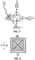
Figure 2 . Scheme of the microfluidic device for the determination of glucose or other solutes in aqueous solutions working in reflection mode. In this scheme: (2) sensor (planar photonic transducer optically active), (3) polarization analyzer, (4) incident linear polarized light beam, (5) optical filter, (6) transmittedlight 12 with its polarization vector parallel to that of the incident beam, (7) transmitted light 11 with its polarization vector perpendicular to that of the incident beam, (8) photodiodes, (9) polarizer, (10) optical fiber. -
Figure 3 . Scheme of the front view of the microfluidic device (1) including the sensor (optically active transducer, 2) with their optical axes (dashed lines) aligned 45° off the polarization vector of the incident light (4). -
Figure 4 . Calibration curve of a microfluidic device based on a simple porous birefringent thin film for the determination of glucose content in aqueous solutions working in transmission mode. The figure shows the evolution with the glucose concentration of the ratio between the transmitted intensities 11/12 defined inFigure 1 . -
Figure 5 . Calibration curve of a microfluidic device based on a birefringent porous multilayer (Bragg microcavity) working in transmission mode for the determination of the concentration of aqueous glucose solutions. The figure shows the evolution with the glucose concentration of the ratio between the transmitted intensities 11/12 defined inFigure 1 - The first aspect of the invention refers to a sensor (2) (also called transducer) for the determination of solute concentration in solutions, formed by one or several porous optically active thin layers prepared by physical vapor deposition in a glancing geometry.
- Preferably, this porous optically active thin film structure is prepared by evaporation through electron bombardment in a vacuum chamber. The distance between the vaporized target and the substrate is between 20 and 100 cm. The substrate (glass, quartz) is flat with the normal to their surface forming an angle of at least 70° with respect to the direction of the flux of atoms vaporized from the target. In an alternative embodiment with the transducer formed by a multilayer photonic structure, the substrate might remain fixed or being azimuthally turned by 180° from one layer to the next. In both cases, the porous planar photonic structure will be optically active. Other techniques of physical vapor deposition of thin layers like magnetron sputtering might also be used for the preparation of similar porous structures.
- As an example of preferred embodiment of the detection method corresponding to the third aspect of the invention a photonic transducer is acting as a sensor (2). It is formed by a porous birefringent thin film of a single material (e.g. TiO2) with a thickness between 0.2 and 3.0 microns, that was prepared in a glancing deposition geometry. It is located in a microfluidic device (1) with its optical axes 45° off the polarization vector of the incident light, as it is shown in
figure 3 . To maximize the sensitivity of the method it is convenient, although not limitative, to use layers with 0.15 or higher birefringence. As it is shown infigure 1 , the light transmitted through the microfluidic chip, that includes the photonic transducer acting as a sensor (2), is analyzed with a polarization analyzer (3). It splits of the electric field of the transmitted light into a parallel 11 and a perpendicular 12 contribution (with respect to the polarization vector of the incident beam). The intensities of the 11 and 12 beams are measured with two photodiodes (8) to evaluate their ratio 11/12. Variations in the concentration of the solute in the solution filling the pores of the photonic transducer will show up as variations of the 11/12 ratio, as it is shown infigure 4 . - As another example of preferred embodiment of the method corresponding to the third aspect of the invention a photonic transducer is acting as a sensor (2). It is formed by a porous Bragg microcavity made of a birefringent porous multilayer system of two alternating materials with different refractive index (e.g. TiO2 and SiO2) of about 80 nm thick with a defect in the center of the multilayer system consisting of a layer of SiO2 of about 200 nm, all these layers having been prepared by physical vapor deposition at glancing geometry. This transducer is located in a microfluidic device (1) with their optical axes 45° off the polarization vector of the incident light, as it is shown in
figure 3 . In this case, the incident polarized light is filtered to a transmission window tuned to the transmission peak of the Bragg microcavity. As it is shown infigure 1 , the light transmitted through the microfluidic device, including the photonic transducer that act as sensor (2), is analyzed with a polarization analyzer (3). It splits the electric field of the transmitted light into a parallel 11 and a perpendicular 12 contributions (with respect to the polarization vector of the incident beam). The intensities of the 11 and 12 beams are measured with photodiodes (8) and it is evaluated their ratio 11/12. Variations in the concentration of the solute in the solution filling the pores of the photonic transducer will show up as variations of the 11/12 ratio, as it is shown in the calibration curve infigure 5 . - In an alternative embodiment of the invention, the transducer can be located on the tip of an optical fiber (10). In this case, the measured reflected light discriminates between the intensities of the components parallel 11 and perpendicular 12 with respect to the polarization vector of the incident light. From an optical point of view, these reflection measurements are compatible with the use of a microfluidic device, although they can also be done by direct immersion of the system fiber-transducer in the solution to be analyzed. An example of realization of the first embodiment is illustrated in
figure 2 . The incident light supplied through an optical fiber (10) is filtered (5) and polarized (9) before reaching the transducer in contact to the solution to be analyzed. The reflected light is measured with photodiodes, discriminating between the intensities of the components parallel 11 and perpendicular 12 with respect to the polarization vector of the incident light. The 11/12 ratio will be a function of the solute concentration in the aqueous solution infiltrated in the optically active porous transducer. - The calibration procedure relating the evolution of the 11/12 intensity ratio and the concentration of aqueous glucose solution is illustrated in
figure 4 . It shows the calibration curve of a microfluidic device based on a single porous birefringent thin layer working in transmission mode. The graph shows the variation of the 11/12 ratio as a function of the glucose concentration in the solution filling the pores of this photonic transducer. - Finally,
figure 5 shows the calibration curve corresponding to a microfluidic device based on a birefringent porous multilayer Bragg microcavity working in transmission mode for the determination of glucose content in aqueous solutions. The graph shows the variation of the 11/12 ratio as a function of the glucose concentration in the solution infiltrating the pores of this photonic transducer. - In a particular embodiment, the first polarizer provides the linearly polarized light that illuminates the transducer and the second serves to select the transmitted/reflected light having a polarization vector either parallel (12) or perpendicular (11) to the polarization vector of the original beam.
- It is possible to functionalize the inner part of the porous structure of the film and multilayer transducers to make them selective to particular solvents. For example, they can be made insensitive to a polar solvent (e.g. water) if such a solvent does not infiltrate within the porous structure of the photonic transducer. A functionalization enabling that only non-polar solvents can infiltrate the porous structure can be carried out by grafting non-polar molecules onto the film oxidic surfaces of these nanostructures. A functionalization of this kind will be specially suited to study mixtures of two solvents making that the optical response of the transducer only accounts for the characteristics of the non-polar solvent selectively infiltrated within the porous structure of the transducer.
Claims (10)
- Sensor for the determination of solute concentrations in solutions, characterized in that said sensor comprises at least one porous, optically active, birefringent layer which is prepared by physical vapor deposition in a glancing geometry.
- Sensor according to claim 1, characterized in that it further comprises two porous one-dimensional photonic crystals formed by birefringent layers with different refractive indexes separated by a porous central layer defining a Bragg microcavity, said crystal layers being prepared by physical vapor deposition in a glancing geometry.
- Sensor according to claims 1 or 2, characterized in that the photonic crystals comprise alternant layers of SiO2 and TiO2.
- Sensor according to anyone of claims 1 to 3, characterized in that the inner part of the pores of the porous layers are functionalized.
- Apparatus for the determination of solute concentrations in solutions which comprises a microfluidic device (1), wherein said apparatus comprises a sensor (2) as defined in anyone of claims 1 to 4, embedded into said microfluidic device.
- Apparatus according to claim 5, characterized in that said microfluidic device (1) comprises two near IR and visible range transparent windows, said sensor (2) being located between said transparent windows in the microfluidic device (1).
- Apparatus according to claim 5, characterized in that the sensor (2) is located on the tip of an optical fiber insertable in the microfluidic device (1).
- Method for the determination of solute concentrations in solutions by means of an apparatus as defined in claim 5, said method characterized in that it comprises:i) contacting sensor (2) with the solution containing the solute whose concentration is to be determined,ii) illuminating linearly polarized light onto sensor (2), once it has been infiltrated with the solution whose solute concentration is to be determined.Iii) analyzing light transmitted through the microfluidic device by means of a polarization analyzer which splits the parallel (11) and perpendicular (12) components with respect to the polarization vector of the light beam illuminating the microfluidic device (1).iv) determining the respective intensities (11/12) of said light beams by means of photodiodes.v) calculating the 11/12 intensities ratio.vi) determining solute concentration from variations in the intensities 11/12 ratio through correlation with a calibration curve.
- Method according to claim 8, characterized in that the sensor (2) is integrated in a microfluidic device (1) which comprises two near IR and visible range transparent windows, said sensor (2) being located between said transparent windows, data being thereby retrieved in reflection mode.
- Method according to claim 8, characterized in that the sensor (2) is located on the tip of an optical fiber which is directly introduced in the solution, data being thereby retrieved in reflection mode, by means of reflection spectra registered from polarizers in aligned or crossed configuration, resulting in spectra as function of solute concentrations.
Applications Claiming Priority (2)
| Application Number | Priority Date | Filing Date | Title |
|---|---|---|---|
| ES201531540A ES2612340B1 (en) | 2015-10-27 | 2015-10-27 | SENSOR, DEVICE AND PROCEDURE FOR THE DETERMINATION OF THE CONCENTRATION OF SOLUTIONS IN DISSOLUTIONS |
| PCT/ES2016/070764 WO2017072388A1 (en) | 2015-10-27 | 2016-10-27 | Sensor, apparatus and method for determining a concentration of a solute in a solution |
Publications (1)
| Publication Number | Publication Date |
|---|---|
| EP3379233A1 true EP3379233A1 (en) | 2018-09-26 |
Family
ID=57482463
Family Applications (1)
| Application Number | Title | Priority Date | Filing Date |
|---|---|---|---|
| EP16805879.0A Withdrawn EP3379233A1 (en) | 2015-10-27 | 2016-10-27 | Sensor, apparatus and method for determining a concentration of a solute in a solution |
Country Status (6)
| Country | Link |
|---|---|
| US (1) | US20180328838A1 (en) |
| EP (1) | EP3379233A1 (en) |
| BR (1) | BR112018008502A2 (en) |
| ES (1) | ES2612340B1 (en) |
| MX (1) | MX2018005253A (en) |
| WO (1) | WO2017072388A1 (en) |
Families Citing this family (3)
| Publication number | Priority date | Publication date | Assignee | Title |
|---|---|---|---|---|
| JP7057976B2 (en) | 2016-03-07 | 2022-04-21 | セントロ ナショナル デ インベスティガシオネス カルディオバスキュラレス カルロス テルセーロ (エフェ.エセ.ペ.) | In vitro method to identify thoracic aortic aneurysm (TAA) in a subject |
| ES2738926A1 (en) | 2018-07-26 | 2020-01-27 | Univ Zaragoza | GRANULISINE, METHOD OF OBTAINING AND USES |
| CN109884063B (en) * | 2019-04-24 | 2021-08-20 | 杭州翔毅科技有限公司 | Acquisition structure for liquid sensor |
Family Cites Families (4)
| Publication number | Priority date | Publication date | Assignee | Title |
|---|---|---|---|---|
| US8280470B2 (en) * | 2006-11-03 | 2012-10-02 | Volcano Corporation | Analyte sensor method and apparatus |
| ES2334318B2 (en) | 2008-09-05 | 2011-11-28 | Universidad Politécnica de Madrid | OPTICAL DETECTION SYSTEM FOR BIO-TESTS OF HIGH SENSITIVITY SINMARCADO. |
| WO2012012437A2 (en) | 2010-07-20 | 2012-01-26 | The Regents Of The University Of California | Temperature response sensing and classification of analytes with porous optical films |
| US9739710B2 (en) * | 2012-10-15 | 2017-08-22 | Nutech Ventures | Optical sensing and separation based on ordered three-dimensional nanostructured surfaces |
-
2015
- 2015-10-27 ES ES201531540A patent/ES2612340B1/en not_active Expired - Fee Related
-
2016
- 2016-10-27 WO PCT/ES2016/070764 patent/WO2017072388A1/en not_active Ceased
- 2016-10-27 US US15/771,854 patent/US20180328838A1/en not_active Abandoned
- 2016-10-27 MX MX2018005253A patent/MX2018005253A/en unknown
- 2016-10-27 EP EP16805879.0A patent/EP3379233A1/en not_active Withdrawn
- 2016-10-27 BR BR112018008502A patent/BR112018008502A2/en not_active IP Right Cessation
Also Published As
| Publication number | Publication date |
|---|---|
| ES2612340A1 (en) | 2017-05-16 |
| WO2017072388A1 (en) | 2017-05-04 |
| BR112018008502A2 (en) | 2018-10-23 |
| ES2612340B1 (en) | 2018-03-09 |
| US20180328838A1 (en) | 2018-11-15 |
| MX2018005253A (en) | 2019-07-04 |
Similar Documents
| Publication | Publication Date | Title |
|---|---|---|
| US9518926B2 (en) | Optical sensor with enhanced sensitivity | |
| EP3137880B1 (en) | Sensing methods and apparatus | |
| CN105190295B (en) | For the method and apparatus of bacterial monitoring | |
| EP1886121A1 (en) | Arrangements, systems and methods capable of providing spectral-domain optical coherence reflectometry for a sensitive detection of chemical and biological sample | |
| WO2015019341A1 (en) | Optical sensor based on multilayered plasmonic structure comprising a nanoporous metallic layer | |
| WO2001088509A1 (en) | Coupled plasmon-waveguide resonance spectroscopic device | |
| US11499917B2 (en) | Biomarker detection apparatus | |
| Wang et al. | An optical waveguide sensor based on mesoporous silica films with a comparison to surface plasmon resonance sensors | |
| Mishra et al. | Surface plasmon resonance based fiber optic sensor for the detection of CrO 4 2− using Ag/ITO/hydrogel layers | |
| Oliva-Ramirez et al. | Liquids analysis with optofluidic bragg microcavities | |
| EP2409136A1 (en) | Device and method for optical sensing of substances or environmental conditions | |
| US20180328838A1 (en) | Sensor, apparatus and method for determining a concentration of a solute in a solution | |
| US9678009B2 (en) | Method for localized surface plasmon resonance sensing system | |
| TW201514009A (en) | Label-free sensing chip and application thereof | |
| CN101809445A (en) | Sensor device for the detection of target components | |
| EP2327955B1 (en) | Optical detection system for labelling-free high-sensitivity bioassays | |
| WO2017176684A1 (en) | Waveguide sensor with nanoporous surface layer | |
| Oliva-Ramírez et al. | Robust polarization active nanostructured 1D Bragg Microcavities as optofluidic label-free refractive index sensor | |
| EP2546633A1 (en) | Laminated structure for measurement of intensity of reflected light, device equipped with laminated structure for measurement of reflected light, and method for determination of thickness and/or mass and/or viscosity of thin film | |
| Dorozinsky et al. | Influence of technological factors on sensitivity of analytical devices based on surface plasmon resonance | |
| JP3961405B2 (en) | Surface plasmon resonance sensor and method for measuring refractive index change | |
| CN101726470B (en) | Refractive index sensor based on surface plasmon interference and detecting method thereof | |
| Han et al. | An ellipsometric surface plasmon resonance system for quantitatively determining the normal of a sensor surface and multi-channel measurement | |
| US20190056389A1 (en) | System and method for determining the presence or absence of adsorbed biomolecules or biomolecular structures on a surface | |
| CN113237849B (en) | A Lithium Niobate Two-dimensional Grating Excited Bloch Surface Wave Biosensor and Method |
Legal Events
| Date | Code | Title | Description |
|---|---|---|---|
| PUAI | Public reference made under article 153(3) epc to a published international application that has entered the european phase |
Free format text: ORIGINAL CODE: 0009012 |
|
| 17P | Request for examination filed |
Effective date: 20180528 |
|
| AK | Designated contracting states |
Kind code of ref document: A1 Designated state(s): AL AT BE BG CH CY CZ DE DK EE ES FI FR GB GR HR HU IE IS IT LI LT LU LV MC MK MT NL NO PL PT RO RS SE SI SK SM TR |
|
| AX | Request for extension of the european patent |
Extension state: BA ME |
|
| DAV | Request for validation of the european patent (deleted) | ||
| DAX | Request for extension of the european patent (deleted) | ||
| STAA | Information on the status of an ep patent application or granted ep patent |
Free format text: STATUS: THE APPLICATION IS DEEMED TO BE WITHDRAWN |
|
| 18D | Application deemed to be withdrawn |
Effective date: 20190305 |