EP3379112A1 - Gearbox for motor vehicle comprising a fork moved by a rocker - Google Patents
Gearbox for motor vehicle comprising a fork moved by a rocker Download PDFInfo
- Publication number
- EP3379112A1 EP3379112A1 EP18156853.6A EP18156853A EP3379112A1 EP 3379112 A1 EP3379112 A1 EP 3379112A1 EP 18156853 A EP18156853 A EP 18156853A EP 3379112 A1 EP3379112 A1 EP 3379112A1
- Authority
- EP
- European Patent Office
- Prior art keywords
- rocker
- gearbox
- spring
- oscillating arm
- axis
- Prior art date
- Legal status (The legal status is an assumption and is not a legal conclusion. Google has not performed a legal analysis and makes no representation as to the accuracy of the status listed.)
- Withdrawn
Links
Images

Classifications
-
- F—MECHANICAL ENGINEERING; LIGHTING; HEATING; WEAPONS; BLASTING
- F16—ENGINEERING ELEMENTS AND UNITS; GENERAL MEASURES FOR PRODUCING AND MAINTAINING EFFECTIVE FUNCTIONING OF MACHINES OR INSTALLATIONS; THERMAL INSULATION IN GENERAL
- F16H—GEARING
- F16H63/00—Control outputs from the control unit to change-speed- or reversing-gearings for conveying rotary motion or to other devices than the final output mechanism
- F16H63/02—Final output mechanisms therefor; Actuating means for the final output mechanisms
- F16H63/30—Constructional features of the final output mechanisms
- F16H63/302—Final output mechanisms for reversing
-
- F—MECHANICAL ENGINEERING; LIGHTING; HEATING; WEAPONS; BLASTING
- F16—ENGINEERING ELEMENTS AND UNITS; GENERAL MEASURES FOR PRODUCING AND MAINTAINING EFFECTIVE FUNCTIONING OF MACHINES OR INSTALLATIONS; THERMAL INSULATION IN GENERAL
- F16H—GEARING
- F16H61/00—Control functions within control units of change-speed- or reversing-gearings for conveying rotary motion ; Control of exclusively fluid gearing, friction gearing, gearings with endless flexible members or other particular types of gearing
- F16H61/24—Providing feel, e.g. to enable selection
-
- F—MECHANICAL ENGINEERING; LIGHTING; HEATING; WEAPONS; BLASTING
- F16—ENGINEERING ELEMENTS AND UNITS; GENERAL MEASURES FOR PRODUCING AND MAINTAINING EFFECTIVE FUNCTIONING OF MACHINES OR INSTALLATIONS; THERMAL INSULATION IN GENERAL
- F16H—GEARING
- F16H63/00—Control outputs from the control unit to change-speed- or reversing-gearings for conveying rotary motion or to other devices than the final output mechanism
- F16H63/02—Final output mechanisms therefor; Actuating means for the final output mechanisms
- F16H63/30—Constructional features of the final output mechanisms
- F16H2063/3089—Spring assisted shift, e.g. springs for accumulating energy of shift movement and release it when clutch teeth are aligned
-
- F—MECHANICAL ENGINEERING; LIGHTING; HEATING; WEAPONS; BLASTING
- F16—ENGINEERING ELEMENTS AND UNITS; GENERAL MEASURES FOR PRODUCING AND MAINTAINING EFFECTIVE FUNCTIONING OF MACHINES OR INSTALLATIONS; THERMAL INSULATION IN GENERAL
- F16H—GEARING
- F16H63/00—Control outputs from the control unit to change-speed- or reversing-gearings for conveying rotary motion or to other devices than the final output mechanism
- F16H63/02—Final output mechanisms therefor; Actuating means for the final output mechanisms
- F16H63/30—Constructional features of the final output mechanisms
- F16H63/3013—Constructional features of the final output mechanisms the final output mechanism being characterised by linkages converting movement, e.g. into opposite direction by a pivoting lever linking two shift rods
-
- F—MECHANICAL ENGINEERING; LIGHTING; HEATING; WEAPONS; BLASTING
- F16—ENGINEERING ELEMENTS AND UNITS; GENERAL MEASURES FOR PRODUCING AND MAINTAINING EFFECTIVE FUNCTIONING OF MACHINES OR INSTALLATIONS; THERMAL INSULATION IN GENERAL
- F16H—GEARING
- F16H63/00—Control outputs from the control unit to change-speed- or reversing-gearings for conveying rotary motion or to other devices than the final output mechanism
- F16H63/02—Final output mechanisms therefor; Actuating means for the final output mechanisms
- F16H63/30—Constructional features of the final output mechanisms
- F16H63/3016—Final output mechanisms varying the leverage or force ratio
Definitions
- the present invention relates to a gearbox for a motor vehicle, and a motor vehicle equipped with such a gearbox.
- Manually operated type gearboxes for motor vehicles generally comprise two parallel shafts supporting pinions of gears producing different gear ratios, to transmit the movement of the engine to the drive wheels in several forward gears.
- An additional shaft carrying sprockets interposed between parallel shaft gears, makes it possible to reverse the direction of travel giving a reverse gear.
- Axially sliding sleeves interposed between free pinions carried by the parallel shafts, slide by sliding towards a free pinion a synchronization and then a interconnection of this pinion on its shaft in order to engage a gear ratio.
- a type of control known sliding sleeves presented in particular by the document EP-A2-0790443 , comprises for each sleeve a control fork engaged in a circular groove of this sleeve, which is guided by an axis parallel to the shafts.
- a control shaft driven in rotation and translation by a speed control lever operated by the driver successively performs a selection movement to select a range, then a movement to move the sleeve bound to this range.
- blasting systems each comprising a positioning ball pushed by a spring in recesses, to maintain the ranges in their positions of dead point and engagement ratios.
- these types of blasting provide little or no no ergonomic assistance for the displacement of the sleeve, comprising the delivery of a force assisting the synchronization movement and commitment of the report.
- the ball positioning can be mounted on small balls forming a ball bearing, which reduce friction by improving ergonomic assistance.
- this system is complex to achieve, and requires a larger race with a longer cam including adapted slopes.
- a known positioning system For movements comprising only two stable end positions, in particular for reversing passage, a known positioning system comprises a toggle spring acting on a passage rocker, which compresses when leaving a position and then relaxes as it approaches. to the other position to maintain it. In this way the spring maintains each end position, and delivers an ergonomic aid by relaxing to assist the engagement of the gear.
- the present invention is intended in particular to avoid these problems of the prior art.
- a gearbox for a motor vehicle comprising a fork moved by a pivoting rocker in a direction between two end positions to engage a ratio of this box, and a toggle spring acting on the rocker which is successively compressed and extended from one end position to the other,
- this gearbox being remarkable in that it comprises an oscillating arm comprising links with the rocker and a housing of the gearbox ensuring that the oscillating arm a pivoting in the direction opposite to that of the rocker, the spring being connected to the rocker and the oscillating arm at two points describing a stroke in opposite directions.
- the gearbox according to the invention may further comprise one or more of the following characteristics, which may be combined with each other.
- the swing arm is connected to the rocker and the casing by two parallel axes.
- the gearbox may comprise successively in the direction of the same transverse axis, a pivot of the rocker, an oscillation axis of the oscillating arm fixed to this rocker, and a reaction axis fixed to the housing and adjusted in a drilling of the swingarm.
- gearbox may comprise successively in the direction of the transverse axis, a first end of the spring attached to the end of the oscillating arm opposite the axis of oscillation, then the second end of this spring.
- the oscillating arm comprises a sheet laid flat on the rocker.
- the housing may comprise a shape covering both the rocker and the swing arm, supporting the pivot and the reaction axis.
- the spring comprises several contiguous turns ending at ends oriented tangentially.
- the movement of the rocker can bring the ends of the spring closer to one another and then a spacing of these ends.
- the invention also relates to a motor vehicle equipped with a gearbox comprising any one of the preceding features.
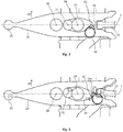
- the figures 1 and 2 have forks 2 for passing forward gears, fixed on longitudinal axes 4 guided in the housing of the gearbox 40, including recesses 16 receiving a log ball systems to fix their operating positions.
- a not shown selection lever actuated by the gearshift lever operated by the driver, acts in a circular groove of the control shaft 6 to effect an axial sliding selection of this shaft.
- One of the ball joints 10 applies to the control shaft 6 a rotation effecting a passage of the reports.
- the other ball 10 causes a mass of inertia external to the gearbox.
- the selection is made by the vertical displacement of a passage finger 12 fitting in a recess of a plate 14 connected to a longitudinal axis 4, the passage through a rotation of the finger driving the selected axis.
- a rocker 24 arranged in a transverse direction, is formed by a cut sheet comprising in a central part a vertical pivot 26 connected to the casing 40.
- the rocker 24 has at one end shown on the right in the figures, a hollow receiving the finger passage 12, and at the other end a boss connecting it to a reverse fork 20 guided by a longitudinal reverse axis 22.
- the rocker 24 reverses the movement of the passage finger 12 to make two end positions of the reverse fork 20, comprising on one side conventionally called back side, indicated by the arrow "AR", a neutral position, and the other the gear ratio commitment.
- An oscillating arm 30 formed by a sheet laid flat on the rocker 24, comprises a vertical oscillation axis 32 fixed to this rocker, which is arranged on the transverse axis T connecting the rocker pivot 26 to the control shaft 6, to the right at a small distance from this pivot.
- a toggle spring 36 comprising a wire wound on several contiguous turns ending in two tangent ends, has a first end 42 fixed on the right end of the oscillating arm 30, a little behind the transverse axis T, at a point disposed to the right at a distance B from the reaction axis 34.
- the distance B is slightly greater than the distance A.
- the second end 44 of the toggle spring 36 is attached to the rocker 24 on the transverse axis T, just next to the right end of the oscillating arm 30.
- the oscillation axis 32 connected to the rocker 24 moves rearward following a fifth stroke C5 towards the rear. Since the fixed reaction axis 34 is substantially at the center of the oscillation arm 30, this arm oscillates, and the first end of the spring 44 moves forwardly along a third stroke C3 equal to the fifth stroke C5 multiplied by the ratio distances B / A.
- the spring 36 provides both without using a blasting system, maintaining the end positions of the rocker 24, and an ergonomic aid for engaging the reverse gear during its relaxation.
Abstract
L'invention a pour objet une boîte vitesses pour véhicule automobile comprenant une fourchette (20) déplacée par un basculeur (24) pivotant dans une direction entre deux positions d'extrémités pour engager un rapport de cette boîte, et un ressort (36) agissant sur ce basculeur (24) qui est successivement comprimé puis détendu en passant d'une position d'extrémité à l'autre, caractérisée en ce qu'elle comporte un bras oscillant (30) comprenant des liaisons avec le basculeur (24) et un carter (40) de la boîte de vitesses assurant à ce bras oscillant (30) un pivotement dans la direction opposée à celle du basculeur (24), le ressort (36) étant relié au basculeur (24) et au bras oscillant (30) en deux points décrivant une course dans des directions opposées.The invention relates to a gearbox for a motor vehicle comprising a fork (20) moved by a rocker (24) pivoting in a direction between two end positions to engage a ratio of this box, and a spring (36) acting on this rocker (24) which is successively compressed and then expanded by passing from one end position to the other, characterized in that it comprises an oscillating arm (30) comprising links with the rocker (24) and a housing (40) of the gearbox providing for this swinging arm (30) pivoting in the direction opposite to that of the rocker (24), the spring (36) being connected to the rocker (24) and the swingarm (30) in two points describing a race in opposite directions.
Description
La présente invention concerne une boîte de vitesses pour un véhicule automobile, ainsi qu'un véhicule automobile équipé d'une telle boîte de vitesses.The present invention relates to a gearbox for a motor vehicle, and a motor vehicle equipped with such a gearbox.
Les boîtes de vitesses du type à commande manuelle pour les véhicules automobiles comportent généralement deux arbres parallèles supportant des couples de pignons réalisant différentes rapports de vitesses, pour transmettre le mouvement du moteur thermique aux roues motrices suivant plusieurs rapports de marche avant.Manually operated type gearboxes for motor vehicles generally comprise two parallel shafts supporting pinions of gears producing different gear ratios, to transmit the movement of the engine to the drive wheels in several forward gears.
Un arbre supplémentaire portant des pignons intercalés entre des pignons des arbres parallèles, permet de réaliser une inversion du sens de marche donnant un rapport de marche arrière.An additional shaft carrying sprockets interposed between parallel shaft gears, makes it possible to reverse the direction of travel giving a reverse gear.
Des manchons coulissants axialement, interposés entre des pignons libres portés par les arbres parallèles, réalisent en coulissant vers un pignon libre une synchronisation puis un crabotage de ce pignon sur son arbre afin d'engager un rapport de vitesse.Axially sliding sleeves, interposed between free pinions carried by the parallel shafts, slide by sliding towards a free pinion a synchronization and then a interconnection of this pinion on its shaft in order to engage a gear ratio.
Un type de commande des manchons coulissants connu, présenté notamment par le document
Un arbre de commande entraîné en rotation et en translation par un levier de commande de vitesse manoeuvré par le conducteur, réalise successivement un mouvement de sélection pour sélectionner une fourchette, puis un mouvement de passage pour déplacer le manchon lié à cette fourchette.A control shaft driven in rotation and translation by a speed control lever operated by the driver, successively performs a selection movement to select a range, then a movement to move the sleeve bound to this range.
D'une manière générale il est connu d'utiliser des systèmes de billage comprenant chacun une bille de positionnement poussée par un ressort dans des creux, pour maintenir les fourchettes dans leurs positions de point mort et d'engagement des rapports. Toutefois ces types de billage assurent peu ou pas d'aide ergonomique pour le déplacement du manchon, comportant la délivrance d'un effort aidant le mouvement de synchronisation et d'engagement du rapport.In general it is known to use blasting systems each comprising a positioning ball pushed by a spring in recesses, to maintain the ranges in their positions of dead point and engagement ratios. However, these types of blasting provide little or no no ergonomic assistance for the displacement of the sleeve, comprising the delivery of a force assisting the synchronization movement and commitment of the report.
En complément la bille de positionnement peut être montée sur des petites billes formant un roulement à billes, qui réduisent les frottements en améliorant l'aide ergonomique. Toutefois ce système est complexe à réaliser, et nécessite une course plus importante avec une came plus longue comprenant des pentes adaptées.In addition the ball positioning can be mounted on small balls forming a ball bearing, which reduce friction by improving ergonomic assistance. However, this system is complex to achieve, and requires a larger race with a longer cam including adapted slopes.
Pour les mouvements comprenant seulement deux positions stables d'extrémité, notamment pour un passage de la marche arrière, un système de positionnement connu comporte un ressort à genouillère agissant sur un basculeur de passage, qui se comprime en quittant une position puis se détend en approchant vers l'autre position pour la maintenir. De cette manière le ressort maintient chaque position d'extrémité, et délivre une aide ergonomique en se détendant pour aider l'engagement du rapport.For movements comprising only two stable end positions, in particular for reversing passage, a known positioning system comprises a toggle spring acting on a passage rocker, which compresses when leaving a position and then relaxes as it approaches. to the other position to maintain it. In this way the spring maintains each end position, and delivers an ergonomic aid by relaxing to assist the engagement of the gear.
Toutefois les courses réduites des basculeurs pour certains passages de rapports ne permettent pas au ressort à genouillère de délivrer une aide ergonomique efficace.However, the reduced strokes of the rockers for certain gear changes do not allow the knee spring to deliver effective ergonomic assistance.
La présente invention a notamment pour but d'éviter ces problèmes de l'art antérieur.The present invention is intended in particular to avoid these problems of the prior art.
Elle propose à cet effet une boîte vitesses pour véhicule automobile comprenant une fourchette déplacée par un basculeur pivotant dans une direction entre deux positions d'extrémités pour engager un rapport de cette boîte, et un ressort à genouillère agissant sur ce basculeur qui est successivement comprimé puis détendu en passant d'une position d'extrémité à l'autre, cette boîte de vitesses étant remarquable en ce qu'elle comporte un bras oscillant comprenant des liaisons avec le basculeur et un carter de la boîte de vitesses assurant à ce bras oscillant un pivotement dans la direction opposée à celle du basculeur, le ressort étant relié au basculeur et au bras oscillant en deux points décrivant une course dans des directions opposées.It proposes for this purpose a gearbox for a motor vehicle comprising a fork moved by a pivoting rocker in a direction between two end positions to engage a ratio of this box, and a toggle spring acting on the rocker which is successively compressed and extended from one end position to the other, this gearbox being remarkable in that it comprises an oscillating arm comprising links with the rocker and a housing of the gearbox ensuring that the oscillating arm a pivoting in the direction opposite to that of the rocker, the spring being connected to the rocker and the oscillating arm at two points describing a stroke in opposite directions.
Un avantage de cette boîte de vitesses est que de manière simple, en conservant le basculeur de passage, par l'ajout du bras oscillant lié à ce basculeur inversant sa direction de pivotement, le ressort peut agir plus efficacement sur ce basculeur grâce à un débattement plus important. On obtient un effort de détente du ressort présentant une aide ergonomique efficace pour l'engagement d'un rapport.An advantage of this gearbox is that in a simple way, keeping the tilter of passage, by the addition of the oscillating arm related to this Tipper reversing its direction of rotation, the spring can act more effectively on this rocker with a greater movement. A spring-biasing effort is obtained which provides effective ergonomic assistance for engaging a gear.
La boîte de vitesses selon l'invention peut de plus comporter une ou plusieurs des caractéristiques suivantes, qui peuvent être combinées entre elles.The gearbox according to the invention may further comprise one or more of the following characteristics, which may be combined with each other.
Avantageusement, le bras oscillant est lié au basculeur et au carter par deux axes parallèles.Advantageously, the swing arm is connected to the rocker and the casing by two parallel axes.
Dans ce cas, la boîte de vitesses peut comporter successivement dans la direction d'un même axe transversal, un pivot du basculeur, un axe d'oscillation du bras oscillant fixé à ce basculeur, et un axe de réaction fixé au carter et ajusté dans un perçage du bras oscillant.In this case, the gearbox may comprise successively in the direction of the same transverse axis, a pivot of the rocker, an oscillation axis of the oscillating arm fixed to this rocker, and a reaction axis fixed to the housing and adjusted in a drilling of the swingarm.
De plus la boîte de vitesses peut comporter successivement dans la direction de l'axe transversal, une première extrémité du ressort fixée à l'extrémité du bras oscillant opposée à l'axe d'oscillation, puis la deuxième extrémité de ce ressort.In addition the gearbox may comprise successively in the direction of the transverse axis, a first end of the spring attached to the end of the oscillating arm opposite the axis of oscillation, then the second end of this spring.
Avantageusement, le bras oscillant comporte une tôle posée à plat sur le basculeur.Advantageously, the oscillating arm comprises a sheet laid flat on the rocker.
Dans ce cas, le carter peut comporter une forme couvrant à la fois le basculeur et le bras oscillant, supportant le pivot et l'axe de réaction.In this case, the housing may comprise a shape covering both the rocker and the swing arm, supporting the pivot and the reaction axis.
Avantageusement, le ressort comporte plusieurs spires jointives se terminant pas des extrémités orientées tangentiellement.Advantageously, the spring comprises several contiguous turns ending at ends oriented tangentially.
En particulier, le déplacement du basculeur peut entraîner un rapprochement des extrémités du ressort l'une de l'autre puis un écartement de ces extrémités.In particular, the movement of the rocker can bring the ends of the spring closer to one another and then a spacing of these ends.
L'invention a aussi pour objet un véhicule automobile équipé d'une boîte de vitesses comprenant l'une quelconque des caractéristiques précédentes.The invention also relates to a motor vehicle equipped with a gearbox comprising any one of the preceding features.
L'invention sera mieux comprise et d'autres caractéristiques et avantages apparaîtront plus clairement à la lecture de la description ci-après donnée à titre d'exemple et de manière non limitative, en référence aux dessins annexés dans lesquels :
- la
figure 1 présente un système de commande d'une boîte de vitesses selon l'invention ; - la
figure 2 présente le basculeur de marche arrière de cette boîte dans une position de point mort ; et - la
figure 3 présente ce basculeur lors de l'engagement de la marche arrière.
- the
figure 1 presents a control system of a gearbox according to the invention; - the
figure 2 present the reverse rocker of this box in a neutral position; and - the
figure 3 presents this rocker when engaging the reverse gear.
Les
Un arbre de commande 6 disposé dans une position appelée par convention verticale, comporte sur le dessus deux biellettes 8 comprenant chacune à leur extrémité une rotule 10.A control shaft 6 arranged in a position called vertical convention, has on the top two
Un levier de sélection non représenté, actionné par le levier de changement de vitesse manoeuvré par le conducteur, agit dans une gorge circulaire de l'arbre de commande 6 pour effectuer un coulissement axial de sélection de cet arbre. Une des rotules 10 applique à l'arbre de commande 6 une rotation effectuant un passage des rapports. L'autre rotule 10 entraine une masse d'inertie externe à la boite de vitesses.A not shown selection lever, actuated by the gearshift lever operated by the driver, acts in a circular groove of the control shaft 6 to effect an axial sliding selection of this shaft. One of the
La sélection se fait par le déplacement vertical d'un doigt de passage 12 s'ajustant dans un creux d'une plaque 14 liée à un axe longitudinal 4, le passage par une rotation de ce doigt entraînant l'axe sélectionné.The selection is made by the vertical displacement of a
Un basculeur 24 disposé dans une direction transversale, est formé par une tôle découpée comportant dans une partie centrale un pivot vertical 26 lié au carter 40. Le basculeur 24 présente à une extrémité présentée à droite sur les figures, un creux recevant le doigt de passage 12, et à l'autre extrémité un bossage le reliant à une fourchette de marche arrière 20 guidée par un axe longitudinal de marche arrière 22.A
Le basculeur 24 inverse le mouvement du doigt de passage 12 pour réaliser deux positions d'extrémité de la fourchette de marche arrière 20, comprenant d'un côté appelé par convention côté arrière, indiqué par la flèche « AR », une position de point mort, et de l'autre l'engagement du rapport de marche arrière.The
Un bras oscillant 30 formé par une tôle posée à plat sur le basculeur 24, comporte un axe vertical d'oscillation 32 fixé à ce basculeur, qui est disposé sur l'axe transversal T reliant le pivot de basculeur 26 à l'arbre de commande 6, vers la droite à une petite distance de ce pivot.An oscillating
Un axe de réaction 34 fixé verticalement au carter de la boîte de vitesses 40 au-dessus du basculeur 24, est ajusté dans un perçage central du bras oscillant 30 disposé sur l'axe transversal T, vers la droite à une petite distance A de l'axe d'oscillation 32.A
Un ressort à genouillère 36 comprenant un fil enroulé sur plusieurs spires jointives se terminant par deux extrémités tangentes, comporte une première extrémité 42 fixée sur l'extrémité droite du bras oscillant 30, un peu en arrière de l'axe transversal T, en un point disposé vers la droite à une distance B de l'axe de réaction 34. La distance B est légèrement supérieure à la distance A.A
La deuxième extrémité 44 du ressort à genouillère 36 est fixée au basculeur 24 sur l'axe transversal T, juste à côté de l'extrémité droite du bras oscillant 30.The
Lors de l'engagement de la marche arrière présenté
Parallèlement l'axe d'oscillation 32 lié au basculeur 24 se déplace vers l'arrière suivant une cinquième course C5 vers l'arrière. L'axe de réaction fixe 34 étant sensiblement au centre du bras d'oscillation 30, ce bras oscille, et la première extrémité du ressort 44 se déplace vers l'avant suivant une troisième course C3 égale à la cinquième course C5 multipliée par le rapport des distances B/A.In parallel, the
En même temps la deuxième extrémité du ressort 44 fixée au basculeur 24, se déplace vers l'arrière suivant une quatrième course C4. On obtient un déplacement différentiel des deux extrémités 42,44 du ressort 36 par l'addition de la troisième course C3 vers l'avant et de la quatrième course C4 vers l'arrière, qui est assez importante pour successivement rapprocher ces deux extrémités l'une de l'autre puis les éloigner.At the same time the second end of the
Le rapprochement des extrémités du ressort 42, 44 l'une de l'autre entraînant un resserrement des spires de ce ressort 36, on obtient pour le mouvement du bras oscillant 30 un effort successif d'opposition puis d'accompagnement de ce mouvement, qui est transmis au basculeur 24 dans un rapport dépendant des rapports de démultiplication.The approach of the ends of the
Avec un simple ajout du bras oscillant 30 sur le basculeur 24, nécessitant peu de modifications de ce basculeur et de la boîte de vitesses, on obtient par l'inversion du sens de déplacement de la première extrémité du ressort 42 une course différentielle importante des extrémités donnant à ce ressort 36 de manière simple et économique une efficacité élevée.With a simple addition of the oscillating
Le ressort 36 assure à la fois sans utiliser de système de billage, un maintien des positions d'extrémité du basculeur 24, et une aide ergonomique pour l'engagement du rapport de marche arrière lors de sa détente.The
Claims (10)
Applications Claiming Priority (1)
| Application Number | Priority Date | Filing Date | Title |
|---|---|---|---|
| FR1752475A FR3064328B1 (en) | 2017-03-24 | 2017-03-24 | GEARBOX FOR A MOTOR VEHICLE COMPRISING A FORK MOVED BY A TILER |
Publications (1)
| Publication Number | Publication Date |
|---|---|
| EP3379112A1 true EP3379112A1 (en) | 2018-09-26 |
Family
ID=58779183
Family Applications (1)
| Application Number | Title | Priority Date | Filing Date |
|---|---|---|---|
| EP18156853.6A Withdrawn EP3379112A1 (en) | 2017-03-24 | 2018-02-15 | Gearbox for motor vehicle comprising a fork moved by a rocker |
Country Status (2)
| Country | Link |
|---|---|
| EP (1) | EP3379112A1 (en) |
| FR (1) | FR3064328B1 (en) |
Citations (4)
| Publication number | Priority date | Publication date | Assignee | Title |
|---|---|---|---|---|
| FR39397E (en) * | 1927-10-05 | 1931-10-19 | Maybach Motorenbau Gmbh | Two-speed shifting for motor cars |
| FR812460A (en) * | 1935-10-16 | 1937-05-11 | Gen Motors Corp | Transmission mechanisms and their controls, in particular for automobiles |
| DE2521139A1 (en) * | 1975-05-13 | 1976-11-25 | Kloeckner Humboldt Deutz Ag | Operating mechanism adjusted by spring force - actuates operating fork in claw clutch of gear and has two-armed joint connection |
| EP0790443A2 (en) | 1996-02-17 | 1997-08-20 | Ford-Werke Aktiengesellschaft | Shift mechanism avoiding neutral during engagement of reverse gear |
-
2017
- 2017-03-24 FR FR1752475A patent/FR3064328B1/en active Active
-
2018
- 2018-02-15 EP EP18156853.6A patent/EP3379112A1/en not_active Withdrawn
Patent Citations (4)
| Publication number | Priority date | Publication date | Assignee | Title |
|---|---|---|---|---|
| FR39397E (en) * | 1927-10-05 | 1931-10-19 | Maybach Motorenbau Gmbh | Two-speed shifting for motor cars |
| FR812460A (en) * | 1935-10-16 | 1937-05-11 | Gen Motors Corp | Transmission mechanisms and their controls, in particular for automobiles |
| DE2521139A1 (en) * | 1975-05-13 | 1976-11-25 | Kloeckner Humboldt Deutz Ag | Operating mechanism adjusted by spring force - actuates operating fork in claw clutch of gear and has two-armed joint connection |
| EP0790443A2 (en) | 1996-02-17 | 1997-08-20 | Ford-Werke Aktiengesellschaft | Shift mechanism avoiding neutral during engagement of reverse gear |
Also Published As
| Publication number | Publication date |
|---|---|
| FR3064328A1 (en) | 2018-09-28 |
| FR3064328B1 (en) | 2019-11-08 |
Similar Documents
| Publication | Publication Date | Title |
|---|---|---|
| US8276473B2 (en) | Sift-drum apparatus and four wheeled vehicle with the same | |
| WO1999057463A1 (en) | Compact gearbox | |
| FR2831634A1 (en) | MASQUEATED SELECTION GEARBOX | |
| FR3064328B1 (en) | GEARBOX FOR A MOTOR VEHICLE COMPRISING A FORK MOVED BY A TILER | |
| FR2940773A1 (en) | Transmission device for self-propelled rolling machine i.e. mowing tractor, has output semi-shafts braked by controlled braking device assembled on forward gear/reverse gear intermediate shaft | |
| FR3077108A1 (en) | DOUBLE CLUTCH GEARBOX COMPRISING A TRANSFER LINK BETWEEN THE TWO PRIMARY TREES | |
| FR2805020A1 (en) | Vehicle gearbox comprises locking finger which prevents engagement of non-selected forks, locking key can tip between two stops so rear gear fork activation causes limited displacement of other forks | |
| EP2063154B1 (en) | Device for internally controlling the gearbox of an automobile | |
| WO2013135990A1 (en) | Clutch-sleeve control for a gearbox, comprising an over-center device | |
| US20070281818A1 (en) | Hypocycloidal Gear Train for Varying the Speed Between Two Shafts and a Bicycle Having Such a Hypocycloidal Gear Train | |
| FR2726619A1 (en) | Vehicle gearbox with two secondary shafts for use with transverse mounted engines | |
| CN111156312A (en) | Gear selecting and shifting mechanism and gearbox | |
| EP2053275A1 (en) | Neutral detection device for internal gearbox control | |
| EP0562946A1 (en) | Control device for the reverse gear of a gearbox with actuating sleeves | |
| US7291081B2 (en) | Variable-ratio transmission device | |
| FR3083583A1 (en) | VEHICLE TRANSMISSION | |
| EP2050988B1 (en) | Device for braking a motor shaft of a gearbox, for engaging a reverse gear | |
| CN211778933U (en) | Gear selecting and shifting mechanism and gearbox | |
| FR2868144A1 (en) | Transmission`s internal control system for motor vehicle, has pinions with driving arms to drive shift forks, for displacing jaw clutches, under action of shifting finger, where arms extend transversely in driving direction of forks | |
| FR2819569A1 (en) | Motor vehicle gearbox internal control mechanism has set of flat bars extending parallel to sliding rods and operated by gear changer | |
| EP3601851B1 (en) | Reduced vibration gearbox | |
| FR2884574A1 (en) | Vehicle gearbox internal control mechanism has set of gear changing nuts of which one is fixed to sliding rod assembly and acts as support for others | |
| WO2000036318A1 (en) | Compact gearbox with two output shafts | |
| FR3067435B1 (en) | SYSTEM FOR CONTROLLING A GEAR-TYPE GEARBOX FOR A MOTOR VEHICLE | |
| FR2861447A1 (en) | Gearbox for motor vehicles driving system, has jaw clutching to couple set of pinions on their shafts for selection of pinions, where pinions for first gear and reverse gear are driven by respective primary shafts |
Legal Events
| Date | Code | Title | Description |
|---|---|---|---|
| PUAI | Public reference made under article 153(3) epc to a published international application that has entered the european phase |
Free format text: ORIGINAL CODE: 0009012 |
|
| STAA | Information on the status of an ep patent application or granted ep patent |
Free format text: STATUS: THE APPLICATION HAS BEEN PUBLISHED |
|
| AK | Designated contracting states |
Kind code of ref document: A1 Designated state(s): AL AT BE BG CH CY CZ DE DK EE ES FI FR GB GR HR HU IE IS IT LI LT LU LV MC MK MT NL NO PL PT RO RS SE SI SK SM TR |
|
| AX | Request for extension of the european patent |
Extension state: BA ME |
|
| STAA | Information on the status of an ep patent application or granted ep patent |
Free format text: STATUS: REQUEST FOR EXAMINATION WAS MADE |
|
| 17P | Request for examination filed |
Effective date: 20190312 |
|
| RBV | Designated contracting states (corrected) |
Designated state(s): AL AT BE BG CH CY CZ DE DK EE ES FI FR GB GR HR HU IE IS IT LI LT LU LV MC MK MT NL NO PL PT RO RS SE SI SK SM TR |
|
| GRAP | Despatch of communication of intention to grant a patent |
Free format text: ORIGINAL CODE: EPIDOSNIGR1 |
|
| STAA | Information on the status of an ep patent application or granted ep patent |
Free format text: STATUS: GRANT OF PATENT IS INTENDED |
|
| INTG | Intention to grant announced |
Effective date: 20191210 |
|
| STAA | Information on the status of an ep patent application or granted ep patent |
Free format text: STATUS: THE APPLICATION IS DEEMED TO BE WITHDRAWN |
|
| 18D | Application deemed to be withdrawn |
Effective date: 20200603 |
|
| RAP1 | Party data changed (applicant data changed or rights of an application transferred) |
Owner name: PSA AUTOMOBILES SA |