EP3379044A1 - Dohc-type internal combustion engine - Google Patents
Dohc-type internal combustion engine Download PDFInfo
- Publication number
- EP3379044A1 EP3379044A1 EP18153791.1A EP18153791A EP3379044A1 EP 3379044 A1 EP3379044 A1 EP 3379044A1 EP 18153791 A EP18153791 A EP 18153791A EP 3379044 A1 EP3379044 A1 EP 3379044A1
- Authority
- EP
- European Patent Office
- Prior art keywords
- intake
- exhaust
- rocker
- pair
- valves
- Prior art date
- Legal status (The legal status is an assumption and is not a legal conclusion. Google has not performed a legal analysis and makes no representation as to the accuracy of the status listed.)
- Granted
Links
- 238000002485 combustion reaction Methods 0.000 title claims abstract description 29
- 230000033001 locomotion Effects 0.000 claims description 11
- 238000011144 upstream manufacturing Methods 0.000 description 3
- 238000005452 bending Methods 0.000 description 2
- 230000005540 biological transmission Effects 0.000 description 2
- 239000002828 fuel tank Substances 0.000 description 2
- 239000012212 insulator Substances 0.000 description 2
- 230000000052 comparative effect Effects 0.000 description 1
Images




Classifications
-
- F—MECHANICAL ENGINEERING; LIGHTING; HEATING; WEAPONS; BLASTING
- F01—MACHINES OR ENGINES IN GENERAL; ENGINE PLANTS IN GENERAL; STEAM ENGINES
- F01L—CYCLICALLY OPERATING VALVES FOR MACHINES OR ENGINES
- F01L1/00—Valve-gear or valve arrangements, e.g. lift-valve gear
- F01L1/12—Transmitting gear between valve drive and valve
- F01L1/18—Rocking arms or levers
- F01L1/185—Overhead end-pivot rocking arms
-
- F—MECHANICAL ENGINEERING; LIGHTING; HEATING; WEAPONS; BLASTING
- F01—MACHINES OR ENGINES IN GENERAL; ENGINE PLANTS IN GENERAL; STEAM ENGINES
- F01L—CYCLICALLY OPERATING VALVES FOR MACHINES OR ENGINES
- F01L1/00—Valve-gear or valve arrangements, e.g. lift-valve gear
- F01L1/02—Valve drive
- F01L1/022—Chain drive
-
- F—MECHANICAL ENGINEERING; LIGHTING; HEATING; WEAPONS; BLASTING
- F01—MACHINES OR ENGINES IN GENERAL; ENGINE PLANTS IN GENERAL; STEAM ENGINES
- F01L—CYCLICALLY OPERATING VALVES FOR MACHINES OR ENGINES
- F01L1/00—Valve-gear or valve arrangements, e.g. lift-valve gear
- F01L1/02—Valve drive
- F01L1/04—Valve drive by means of cams, camshafts, cam discs, eccentrics or the like
- F01L1/047—Camshafts
- F01L1/053—Camshafts overhead type
-
- F—MECHANICAL ENGINEERING; LIGHTING; HEATING; WEAPONS; BLASTING
- F01—MACHINES OR ENGINES IN GENERAL; ENGINE PLANTS IN GENERAL; STEAM ENGINES
- F01L—CYCLICALLY OPERATING VALVES FOR MACHINES OR ENGINES
- F01L1/00—Valve-gear or valve arrangements, e.g. lift-valve gear
- F01L1/02—Valve drive
- F01L1/04—Valve drive by means of cams, camshafts, cam discs, eccentrics or the like
- F01L1/047—Camshafts
- F01L1/053—Camshafts overhead type
- F01L2001/0537—Double overhead camshafts [DOHC]
-
- F—MECHANICAL ENGINEERING; LIGHTING; HEATING; WEAPONS; BLASTING
- F01—MACHINES OR ENGINES IN GENERAL; ENGINE PLANTS IN GENERAL; STEAM ENGINES
- F01L—CYCLICALLY OPERATING VALVES FOR MACHINES OR ENGINES
- F01L2305/00—Valve arrangements comprising rollers
-
- F—MECHANICAL ENGINEERING; LIGHTING; HEATING; WEAPONS; BLASTING
- F02—COMBUSTION ENGINES; HOT-GAS OR COMBUSTION-PRODUCT ENGINE PLANTS
- F02D—CONTROLLING COMBUSTION ENGINES
- F02D41/00—Electrical control of supply of combustible mixture or its constituents
- F02D41/0002—Controlling intake air
- F02D2041/001—Controlling intake air for engines with variable valve actuation
-
- Y—GENERAL TAGGING OF NEW TECHNOLOGICAL DEVELOPMENTS; GENERAL TAGGING OF CROSS-SECTIONAL TECHNOLOGIES SPANNING OVER SEVERAL SECTIONS OF THE IPC; TECHNICAL SUBJECTS COVERED BY FORMER USPC CROSS-REFERENCE ART COLLECTIONS [XRACs] AND DIGESTS
- Y02—TECHNOLOGIES OR APPLICATIONS FOR MITIGATION OR ADAPTATION AGAINST CLIMATE CHANGE
- Y02T—CLIMATE CHANGE MITIGATION TECHNOLOGIES RELATED TO TRANSPORTATION
- Y02T10/00—Road transport of goods or passengers
- Y02T10/10—Internal combustion engine [ICE] based vehicles
- Y02T10/12—Improving ICE efficiencies
Definitions
- a DOHC-type internal combustion engine is known in Japanese Patent Application Laid-Open No. 2015-94238 .
- an intake-side camshaft and an exhaust-side camshaft are disposed in parallel to each other with plug holes interposed therebetween, and support portions of rocker arms having a same shape are disposed around the plug holes.
- the intake valves can be disposed closer to each other and also the exhaust valves can be disposed closer to each other, in the direction along the axes of the intake-side and exhaust-side camshafts, while securing the length of each rocker arm to reduce the rocking angle while avoiding interference with the plug hole, and downsizing of the cylinder head can be achieved.
- a distance between the first and second valve connection portions of the one pair of rocker arms is set shorter than a distance between the first and second support portions, and a distance between the third and fourth valve connection portions of the other pair of the rocker arms is set longer than a distance between the third and fourth support portions.
- a tubular portion is arranged integrally in the cylinder head, the tubular portion forming at least a part of the plug hole, first and second rocker shafts are disposed on opposite sides of the plug hole in a direction along the axes of the intake-side and exhaust-side camshafts, the first and second rocker shafts supporting the first and second support portions individually, a pair of support recesses are formed in the tubular portion, end portions on the plug hole side of the first and second rocker shafts being fitted to the pair of support recesses respectively, and axial movement of at least one of the first and second rocker shafts is prevented by an anti-come-off plug and an inner end closing portion of at least one of the pair of support recesses, the anti-come-off plug being attached to the cylinder head so as to abut, from a side opposite to the plug hole, against at least the one of the first and second rocker shafts.
- the pair of support recesses are formed in the tubular portion that forms at least a part of the plug hole and is arranged integrally in the cylinder head, the end portions on the plug hole side of the first and second rocker shafts being respectively fitted to the pair of support recesses, the first and second rocker shafts individually supporting the first and second support portions, and axial movement of at least one of the first and second rocker shafts is prevented by the inner end closing portion of at least one support recess and the anti-come-off plug that is attached to the cylinder head so as to abut against at least the one rocker shaft. Therefore, axial movement of at least the one rocker shaft can be prevented utilizing the tubular portion, and assembling efficiency of at least the one rocker shaft and productivity of the internal combustion engine can be thereby improved.
- a part of a cam chain chamber is formed in the cylinder head, the cam chain chamber being disposed so that an other of the first and second rocker shafts is sandwiched between the cam chain chamber and the plug hole, and an anti-come-off pin is attached to the cylinder head, the anti-come-off pin engaging with an annular locking groove that is formed on an outer surface of an intermediate portion of the other rocker shaft.
- a single third rocker shaft is formed to have a step so that a portion of the third rocker shaft which is inserted to the third support portion and a portion of the third rocker shaft which is inserted to the fourth support portion are made different in an outside diameter, the third rocker shaft being common to the third and fourth support portions.
- the single third rocker shaft is formed to have a step so as to cope with an event that the inside diameters of the support holes formed in the third and fourth support portions are different from each other.
- FIG. 1 to FIG. 8 An embodiment of the present invention will be explained referring to FIG. 1 to FIG. 8 attached. Also, in the explanation described below, up, down, front, rear, left, and right are directions when viewed by an occupant riding a two-wheeled motor vehicle.
- an engine body 20 of a single cylinder DOHC-type internal combustion engine E is mounted so as to be disposed below the main frames 14 as seen in a side view.
- An axle 21 of a rear wheel WR is pivotally supported by the rear end portion of a swing arm 22, and the front end portion of this swing arm 22 is supported by the lower portions of the pivot frames 17 in the body frame F through a spindle 23 in an up-down swingable manner.
- a link mechanism 25 is arranged between a bracket 24 and the swing arm 22, the bracket 24 being arranged in the lower portion of the pivot frames 17 in the body frame F, and a rear cushion unit 27 that extends in the up-down direction is arranged between a link member 26 and the upper portion of the pivot frames 17, the link member 26 configuring a part of the link mechanism 25.
- a transmission not illustrated is stored within a crankcase 28 that configures a part of the engine body 20, an output shaft 32 of the transmission protrudes sideways to the left from the crankcase 28, and a drive chain 35 of an endless shape is wound around a driving sprocket 33 and a follower sprocket 34, the driving sprocket 33 being arranged on the output shaft 32, the follower sprocket 34 being arranged on the axle 21 of the rear wheel WR.
- a fuel tank 36 is arranged above the engine body 20 and on the both main frames 14, and a riding seat 37 is disposed behind the fuel tank 36 so as to be supported by the seat rails 18.
- the engine body 20 includes the crankcase 28, a cylinder body 29, a cylinder head 30, and a head cover 31, the cylinder body 29 being joined to the front side upper portion of the crankcase 28 and extending upward, the cylinder head 30 being joined to the upper portion of the cylinder body 29, the head cover 31 being joined to the upper portion of the cylinder head 30, and the engine body 20 is mounted on the body frame F with such attitude that a cylinder axis C is slightly tilted forward.
- the cylinder head 30 and the head cover 31 are joined to each other on a second imaginary plane PL2 that crosses the cylinder axis C with the forward tilt angle of the second imaginary plane PL2 slightly larger than that of a first imaginary plane PL1 that tilts so as to be positioned at an upper position as it goes to the rear along the vehicle longitudinal direction and is orthogonal to the cylinder axis C.
- a pair of left and right exhaust ports 40 are arranged in a front wall 30a of the cylinder head 30, and an exhaust device 41 of the internal combustion engine E includes a pair of exhaust pipes 42 and a pair of left and right mufflers 43 as shown clearly in FIG. 1 , the pair of exhaust pipes 42 respectively coming around the left and right of the engine body 20 with the upstream side end portions of the exhaust pipes 42 being connected to the exhaust ports 40, the pair of left and right mufflers 43 being connected respectively to the downstream side ends of the exhaust pipes 42 and being disposed above the rear wheel WR.
- an intake connection pipe portion 45 that configures a single intake port 44 is protruded obliquely upward to the rear
- an intake device 46 of the internal combustion engine E includes a throttle body 47, an insulator 48, a connecting tube 49, and an air cleaner 50, the throttle body 47 adjusting the air quantity that is supplied to the intake port 44, the insulator 48 connecting the intake connection pipe portion 45 and the throttle body 47 to each other, the downstream side end of the connecting tube 49 being connected to the upstream side end of the throttle body 47, the air cleaner 50 being disposed below the riding seat 37 so that the upstream side end of the connecting tube 49 is connected to the air cleaner 50 (refer to FIG. 1 ).
- a combustion chamber 39 is formed between the cylinder body 29 and the cylinder head 30, the top portion of a piston 38 facing the combustion chamber 39, the piston 38 being slidably fitted to the cylinder body 29, and a plug hole 55 is arranged so as to straddle between the cylinder head 30 and the head cover 31 that is attached to the cylinder head 30, an ignition plug 56 being to be inserted to the plug hole 55, the ignition plug 56 being attached to the cylinder head 30 so that the tip end of the ignition plug 56 faces the top portion of the combustion chamber 39.
- a pair of intake valves 51L, 51R and a pair of exhaust valves 52L, 52R are disposed so as to be capable of opening/closing motion, the pair of intake valves 51L, 51R controlling the intake quantity that flows in from the intake port 44 to the combustion chamber 39, the pair of exhaust valves 52L, 52R controlling the exhaust quantity that is discharged from the combustion chamber 39 to the exhaust port 40, and a valve chamber 54 is formed between the cylinder head 30 and the head cover 31, the valve chamber 54 storing a valve train 53 that openably/closably drives the intake valves 51L, 51R and the exhaust valves 52L, 52R.
- the valve train 53 includes an intake-side camshaft 57 and an exhaust-side camshaft 58, intake-side rocker arms 59L, 59R, and exhaust-side rocker arms 60L, 60R, the intake-side camshaft 57 and the exhaust-side camshaft 58 extending in parallel to each other in the vehicle width direction at positions that are apart from each other in the vehicle longitudinal direction and being disposed at positions that sandwich the plug hole 55 between the intake-side camshaft 57 and the exhaust-side camshaft 58, the paired intake-side rocker arms 59L, 59R being interposed between the intake-side camshaft 57 and the intake valves 51L, 51R so as to correspond to the intake valves 51L, 51R, the paired exhaust-side rocker arms 60L, 60R being interposed between the exhaust-side camshaft 58 and the exhaust valves 52L, 52R so as to correspond to the exhaust valves 52L, 52R.
- the intake valves 51L, 51R are disposed behind the plug hole 55 in the vehicle longitudinal direction so as to be arrayed in the direction along the axis of the intake-side camshaft 57, namely, the vehicle width direction
- the exhaust valves 52L, 52R are disposed forward of the plug hole 55 in the vehicle longitudinal direction so as to be arrayed in the direction along the axis of the exhaust-side camshaft 58, namely, the vehicle width direction
- the intake valves 51L, 51R and the exhaust valves 52L, 52R are disposed around the plug hole 55.
- the intake-side camshaft 57 and the exhaust-side camshaft 58 are rotatably supported by a shaft support portion 30c and a cam holder 61, the shaft support portion 30c being integrally arranged in the cylinder head 30, the cam holder 61 being fastened to the shaft support portion 30c by a plurality of, for example, eight cam holder attaching bolts 62.
- the cam holder 61 is formed so as to integrally include a left-side rotation support portion 61a, a right-side rotation support portion 61b, a rear connection portion 61c, and a front connection portion 61d, the left-side rotation support portion 61a extending in the vehicle longitudinal direction so as to rotatably support a portion on the left side in the vehicle width direction of the intake-side camshaft 57 and the exhaust-side camshaft 58 between the shaft support portion 30c and the left-side rotation support portion 61a, the right-side rotation support portion 61b extending in the vehicle longitudinal direction so as to rotatably support a portion on the right side in the vehicle width direction of the intake-side camshaft 57 and the exhaust-side camshaft 58 between the shaft support portion 30c and the right-side rotation support portion 61b and being disposed on the right side in the vehicle width direction of the left-side rotation support portion 61a, the rear connection portion 61c connecting between rear portions along the vehicle longitudinal direction of the left-side
- One intake valve 51L out of the pair of intake valves 51L, 51R is disposed on the left-side in the vehicle width direction of the left-side rotation support portion 61a and below the intake-side camshaft 57, and one exhaust valve 52L out of the pair of exhaust valves 52L, 52R is disposed on the left side in the vehicle width direction of the left-side rotation support portion 61a and below the exhaust-side camshaft 58.
- the other intake valve 51R is disposed between the left-side rotation support portion 61a and the right-side rotation support portion 61b and below the intake-side camshaft 57
- the other exhaust valve 52R is disposed between the left-side rotation support portion 61a and the right-side rotation support portion 61b and below the exhaust-side camshaft 58.
- the intake-side rocker arm 59L is formed so as to include a first valve connection portion 64a and a first support portion 65a at opposite ends, the first valve connection portion 64a being operatively connected with the intake valve 51L, the first support portion 65a being rockably supported by the shaft support portion 30c of the cylinder head 30, the intake-side rocker arm 59R is formed so as to include a second valve connection portion 64b and a second support portion 65b at opposite ends, the second valve connection portion 64b being operatively connected with the intake valve 51R, the second support portion 65b being rockably supported by the shaft support portion 30c, the exhaust-side rocker arm 60L is formed so as to include a third valve connection portion 64c and a third support portion 65c at opposite ends, the third valve connection portion 64c being operatively connected with the exhaust valve 52L, the third support portion 65c being rockably supported by the shaft support portion 30c and the exhaust-side rocker arm 60R is formed so as to include a fourth valve connection portion 64d and a fourth support portion 65d
- the first and second support portions 65a, 65b of one pair of the intake-side rocker arms 59L, 59R out of the pair of intake-side rocker arms 59L, 59R and the pair of exhaust-side rocker arms 60L, 60R are disposed around the plug hole 55 and between the intake valves 51L, 51R and the exhaust valves 52L, 52R in the direction orthogonal to the axes of the intake-side and exhaust-side camshafts 57, 58 (the vehicle longitudinal direction), and the third and fourth support portions 65c, 65d of the other pair of the exhaust-side rocker arms 60L, 60R out of the pair of intake-side rocker arms 59L, 59R and the pair of exhaust-side rocker arms 60L, 60R are disposed outside a region between the intake valves 51L, 51R and the exhaust valves 52L, 52R in the direction orthogonal to the axes of the intake-side and exhaust-side camshafts 57, 58 (the
- the first support portion 65a of one intake-side rocker arm 59L out of the one pair of the intake-side rocker arms 59L, 59R is disposed between a third imaginary plane PL3 and a fourth imaginary plane PL4, the third imaginary plane PL3 extending parallel to the axis of the intake-side camshaft 57 and including the operation axes of the intake valves 51L, 51R, the fourth imaginary plane PL4 extending parallel to the axis of the exhaust-side camshaft 58 and including the operation axes of the exhaust valves 52L, 52R, and similarly to the first support portion 65a, the second support portions 65b of the other intake-side rocker arm 59R out of the one pair of the intake-side rocker arms 59L, 59R is also disposed between the third and fourth imaginary planes PL3, PL4. Further, the third and fourth support portions 65c, 65d of the other pair of the exhaust-side rocker arms 60L, 60R are disposed outside
- first support portion 65a and the second support portion 65b are disposed in slits 70L, 70R that are formed in the shaft support portion 30c of the cylinder head 30 forward in the vehicle longitudinal direction of the intake-side camshaft 57, and are rockably supported respectively by the cylinder head 30 through first and second rocker shafts 71L, 71R that are attached to the shaft support portion 30c.
- the third support portion 65c and the fourth support portion 65d are disposed in slits 72L, 72R that are formed in the shaft support portion 30c of the cylinder head 30 forward in the vehicle longitudinal direction of the exhaust-side camshaft 58, and are rockably supported by the cylinder head 30 through a single third rocker shaft 73 that is attached to the shaft support portion 30c.
- a distance between the first and second valve connection portions 64a, 64b of the pair of intake-side rocker arms 59L, 59R is set shorter than a distance between the first and second support portions 65a, 65b, and as shown in FIG. 7 , a distance L1 between the center portions in the width direction of the first and second valve connection portions 64a, 64b is shorter than a distance L3 between the center portions in the width direction of the first and second support portions 65a, 65b. Also, a distance between the third and fourth valve connection portions 64c, 64d of the pair of exhaust-side rocker arms 60L, 60R is set longer than a distance between the third and fourth support portions 65c, 65d, and as shown in FIG.
- a distance L2 between the center portions in the width direction of the third and fourth valve connection portions 64c, 64d is set longer than a distance L4 between the center portions in the width direction of the third and fourth support portions 65c, 65d.
- the pair of intake-side rocker arms 59L, 59R are formed so as to be bent in the direction approaching to each other as it goes to the intake valves 51L, 51R side from the first and second support portions 65a, 65b, and the pair of exhaust-side rocker arms 60L, 60R are formed so as to be bent in the direction separating from each other as it goes to the exhaust valves 52L, 52R side from the third and fourth support portions 65c, 65d.
- the intake-side rocker arm 59L and the exhaust-side rocker arm 60R have a same shape and are commonalized, the intake-side rocker arm 59L being disposed on one side (the left side in the vehicle direction in the present embodiment) in the direction along the axis of the intake-side camshaft 57 out of the pair of intake-side rocker arms 59L, 59R, the exhaust-side rocker arm 60R being disposed on the other side (the right side in the vehicle direction in the present embodiment) in the direction along the axis of the exhaust-side camshaft 58 out of the pair of exhaust-side rocker arms 60L, 60R, and the intake-side rocker arm 59R and the exhaust-side rocker arm 60L have a same shape and are commonalized, the intake-side rocker arm 59R being disposed on the other side (the right side in the vehicle direction in the present embodiment) in the direction along the axis of the intake-side camshaft 57 out of the pair of intake-side rocker
- the intake-side rocker arms 59L, 59R and the exhaust-side rocker arms 60L, 60R have two kinds of shapes
- first support holes 83 having a same inside diameter are respectively formed in the first and fourth support portions 65a, 65d of one kind of the rocker arms, namely, the intake-side rocker arm 59L and the exhaust-side rocker arm 60R
- second support holes 84 having a same inside diameter are respectively formed in the second and third support portions 65b, 65c of the other kind of the rocker arms, namely, the intake-side rocker arm 59R and the exhaust-side rocker arm 60L so that the inside dimeter becomes different from that of the first support hole 83
- the inside diameter of the first support hole 83 is set smaller than the inside diameter of the second support hole 84.
- an outside diameter d1 of the first rocker shaft 71L that is inserted to the first support hole 83 of the first support portion 65a is set smaller than an outside diameter d2 of the second rocker shaft 71R that is inserted to the second support hole 84 of the second support portion 65b (dl ⁇ d2).
- the single third rocker shaft 73 that is common to the third and fourth support portions 65c, 65d is formed to have a step so that a portion of the third rocker shaft 73 which is inserted to the third support portion 65c and a portion of the third rocker shaft 73 which is inserted to the fourth support portion 65d are made different in the outside diameter, and the third rocker shaft 73 is formed so that a small diameter portion 73a and a large diameter portion 73b are connected to each other coaxially, the small diameter portion 73a having the outside diameter d1 same as that of the first rocker shaft 71L so as to be inserted to the first support hole 83 of the fourth support portion 65d, the large diameter portion 73b having the outside diameter d2 same as that of the second rocker shaft 71R so as to be inserted to the second support hole 84 of the third support portion 65c.
- the plug hole 55 is configured with a plug bore 66, a cam holder side tubular portion 67, a head cover side tubular portion 68, and a through hole 69, the plug bore 66 being formed in the shaft support portion 30c of the cylinder head 30, the cam holder side tubular portion 67 being arranged integrally to the left-side rotation support portion 61a of the cam holder 61 so as to be connected to the plug bore 66, the head cover side tubular portion 68 being arranged integrally to the head cover 31 with a gasket 74 being interposed between the upper end of the cam holder side tubular portion 67, the through hole 69 being arranged in a ceiling wall 31a of the head cover 31 so as to be connected to the head cover side tubular portion 68.
- a long hole portion 55a is formed, the long hole portion 55a being formed long in the direction orthogonal to the axes of the intake-side and exhaust-side camshafts 57, 58, the long hole portion 55a is formed by that the cam holder side tubular portion 67 and the head cover side tubular portion 68 are made have a section with an elliptical shape extending long in the direction orthogonal to the axes of the intake-side and exhaust-side camshafts 57, 58, and a step portion 67a that faces to the head cover 31 side is formed within the cam holder side tubular portion 67.
- cam holder attaching bolts 62 out of the eight cam holder attaching bolts 62 for fastening the cam holder 61 to the shaft support portion 30c of the cylinder head 30 are disposed so as to abut against and engage with the step portion 67a.
- a breather plate 79 is fastened to the head cover 31, a breather chamber 80 is formed between the breather plate 79 and the head cover 31 so as to surround the long hole portion 55a of the plug hole 55, and a lead out pipe 81 is attached to the head cover 31 in order to lead out gas from the breather chamber 80 to the air cleaner 50 side in the intake device 46.
- follower sprockets 75, 76 are fixed to protruding end portions of the intake-side camshaft 57 and the exhaust-side camshaft 58 from the right-side rotation support portion 61b of the cam holder 61, and a cam chain 77 is wound around the follower sprockets 75, 76 in order to transfer the rotational power to the intake-side and exhaust-side camshafts 57, 58.
- a cam chain chamber 78 for allowing the cam chain 77 to travel is formed in the crankcase 28, the cylinder body 29, and the cylinder head 30.
- a tubular portion 85 for forming at least a part (a part in the present embodiment) of the plug hole 55 is arranged integrally in the shaft support portion 30c of the cylinder head 30, and the first and second rocker shafts 71L, 71R for supporting the first and second support portions 65a, 65b individually are disposed on opposite sides of the plug hole 55 in the direction along the axes of the intake-side and the exhaust-side camshafts 57, 58.
- a pair of support recesses 86, 87 are formed in the tubular portion 85, end portions on the plug hole 55 side of the first and second rocker shafts 71L, 71R being fitted to the pair of support recesses 86, 87 respectively, and axial movement of at least one of the first and second rocker shafts 71L, 71R (the first rocker shaft 71L in the present embodiment) is prevented by the inner end closing portion of at least one of the pair of support recesses 86, 87 (the support recess 86 in the present embodiment) and an anti-come-off plug 88 that is attached to the cylinder head 30 so as to abut, from the side opposite to the plug hole 55, against the rocker shaft 71L which is at least one of the first and second rocker shafts 71L, 71R.
- the anti-come-off plug 88 is a bolt in the present embodiment, and the anti-come-off plug 88 that is a bolt may be formed so as to be integral with the first
- a part of the cam chain chamber 78 is formed in the cylinder head 30, the part of the cam chain chamber 78 being disposed so that the other rocker shaft of the first and second rocker shafts 71L, 71R, namely, the second rocker shaft 71R is sandwiched between the cam chain chamber 78 and the plug hole 55, and a first anti-come-off pin 90 penetrates the cam holder 61, is press-fitted into the cylinder head 30 so as to prevent axial movement of the second rocker shaft 72R, and is thereby attached to the cylinder head 30, the first anti-come-off pin 90 engaging with a first annular locking groove 89 that is formed on the outer surface of the intermediate portion of the second rocker shaft 71R.
- a second annular locking groove 92 is formed in the large diameter portion 73b of the third rocker shaft 73, a second anti-come-off pin 91 penetrates the cam holder 61 and is press-fitted into the cylinder head 30, the second anti-come-off pin 91 engaging with the second annular locking groove 92 and preventing axial movement of the third rocker shaft 73, and a cap 93 is screwed into the left side wall of the cylinder head 30, the cap 93 abutting against the end portion of the third rocker shaft 73 on the side opposite to the cam chain chamber 78.
- the cap 93 is a bolt in the present embodiment, the cap 93 that is a bolt may be formed so as to be integral with the third rocker shaft 73, and in this case, the second annular locking groove 92 and the second anti-come-off pin 91 become unnecessary.
- Two pairs of the rocker arms namely, the pair of intake-side rocker arms 59L, 59R and the pair of exhaust-side rocker arms 60L, 60R are respectively interposed between the intake-side camshaft 57 and the exhaust-side camshaft 58 and the intake valves 51L, 51R and the exhaust valves 52L, 52R, the intake-side camshaft 57 and the exhaust-side camshaft 58 being disposed in parallel to each other with the plug hole 55 interposed therebetween, the intake valves 51L, 51R and the exhaust valves 52L, 52R being disposed around the plug hole 55 and are arrayed by pairs in the axial direction of the intake-side and exhaust-side camshafts 57, 58.
- the first and second support portions 65a, 65b of one pair of the intake-side rocker arms 59L, 59R are disposed around the plug hole 55 and between the intake valves 51L, 51R and the exhaust valves 52L, 52R in the direction orthogonal to the axes of the intake-side and exhaust-side camshafts 57, 58.
- the third and fourth support portions 65c, 65d of the other pair of the exhaust-side rocker arms 60L, 60R are disposed outside a region between the intake valves 51L, 51R and the exhaust valves 52L, 52R in the direction orthogonal to the axes of the intake-side and exhaust-side camshafts 57, 58.
- the intake valves 51L, 51R can be disposed closer to each other and the exhaust valves 52L, 52R can be disposed closer to each other, in the direction along the axes of the intake-side and exhaust-side camshafts 57, 58, while securing the length of respective rocker arms 59L, 59R; 60L, 60R to reduce the rocking angle while avoiding interference with the plug hole 55, and downsizing of the cylinder head 30 can be achieved.
- the distance between the first and second valve connection portions 64a, 64b of the intake-side rocker arms 59L, 59R is set shorter than the distance between the first and second support portions 65a, 65b
- the distance between the third and fourth valve connection portions 64c, 64d of the exhaust-side rocker arms 60L, 60R is set longer than the distance between the third and fourth support portions 65c, 65d, and therefore the intake valves 51L, 51R can be disposed closer to each other and the exhaust valves 52L, 52R can be disposed closer to each other, in the direction along the axes of the intake-side and exhaust-side camshafts 57, 58.
- the distance between the third and fourth support portions 65c, 65d that are disposed outside a region between the intake valves 51L, 51R and the exhaust valves 52L, 52R in the direction orthogonal to the axes of the intake-side and exhaust-side camshafts 57, 58 can be made comparatively short. As a result, it can contribute to further downsizing of the cylinder head 30.
- the intake-side rocker arm 59L, on one side along the axes of the intake-side and exhaust-side camshafts 57, 58 out of the intake-side rocker arms 59L, 59R, and the exhaust-side rocker arm 60R, on the other side along the axes of the intake-side and exhaust-side camshafts 57, 58 out of the exhaust-side rocker arms 60L, 60R, have a same shape and are commonalized.
- the intake-side rocker arm 59R on the other side along the axes of the intake-side and exhaust-side camshafts 57, 58 out of the intake-side rocker arms 59L, 59R, and the exhaust-side rocker arm 60L, on one side along the axes of the intake-side and exhaust-side camshafts 57, 58 out of the exhaust-side rocker arms 60L, 60R, have a same shape and are commonalized.
- the pair of intake-side rocker arms 59L, 59R on the intake valves 51L, 52R side and the pair of exhaust-side rocker arms 60L, 60R on the exhaust valves 52L, 52R side commonalize the bending direction of these rocker arms 59L, 59R; 60L, 60R between on the intake side and on the exhaust side and can be thereby consolidated into two kinds of shapes, the number of components can be reduced, and assembling efficiency can be improved.
- the inside diameter of the first support hole 83 and the inside diameter of the second support hole 84 are set different from each other, the first support hole 83 being formed in the first and fourth support portions 65a, 65d of one kind of the intake-side rocker arm 59L and the exhaust-side rocker arm 60R out of two pairs of the rocker arms 59L, 59R; 60L, 60R each pair having two kinds of shapes, the second support hole 84 being formed in the second and third support portions 65b, 65c of the other kind of the intake-side rocker arm 59R and the exhaust-side rocker arm 60L. Therefore, while achieving downsizing of the cylinder head 30, assembling position of each of the rocker arms 59L, 59R; 60L, 60R can be made clear, misassembling can be prevented, and assembling efficiency can be improved.
- tubular portion 85 forming at least a part of the plug hole 55 is arranged integrally in the cylinder head 30, the first and second rocker shafts 71L, 71R supporting the first and second support portions 65a, 65b individually are disposed on opposite sides of the plug hole 55 in the direction along the axes of the intake-side and exhaust-side camshafts 57, 58.
- the pair of support recesses 86, 87 are formed in the tubular portion 85, end portions on the plug hole 55 side of the first and second rocker shafts 71L, 71R being fitted to the pair of support recesses 86, 87 respectively, and axial movement of the first rocker shaft 71L that is at least one of the first and second rocker shafts 71L, 71R is prevented by the anti-come-off plug 88 and the inner end closing portion of the support recess 86 which is at least one of the pair of support recesses 86, 87, the anti-come-off plug 88 being attached to the cylinder head 30 so as to abut against at least the rocker shaft 71L from the side opposite to the plug hole 55. Therefore, axial movement of the first rocker shaft 71L can be prevented utilizing the tubular portion 85, and assembling efficiency of the first rocker shaft 71L and productivity of the internal combustion engine E can be thereby improved.
- a part of the cam chain chamber 78 is formed in the cylinder head 30, the cam chain chamber 78 being disposed so that the second rocker shaft 71R that is the other of the first and second rocker shafts 71L, 71R is sandwiched between the cam chain chamber 78 and the plug hole 55, and the first anti-come-off pin 90 is attached to the cylinder head 30, the first anti-come-off pin 90 engaging with the first annular locking groove 89 that is formed on the outer surface of the intermediate portion of the second rocker shaft 71R. Therefore, it is not required to reserve a special space between the plug hole 55 and the cam chain chamber 78, and downsizing of the cylinder head 30 can be thereby achieved, the special space being for preventing coming-off of the second rocker shaft 71R.
- the single third rocker shaft 73 which is common to the third and fourth support portions 65c, 65d is formed to have a step so that a portion of the third rocker shaft 73 which is inserted to the third support portion 65c and a portion of the third rocker shaft 73 which is inserted to the fourth support portion 65d are made different in the outside diameter. Therefore, such event can be coped with that the inside diameters of the first and second support holes 83, 84 formed in the third and fourth support portions 65c, 65d are different from each other, a space required for supporting the third and fourth support portions 65c, 65d is reduced, the coming-off structure for the third rocker shaft 73 is simplified, and assembling efficiency is improved which can contribute to improvement of the productivity.
Landscapes
- Engineering & Computer Science (AREA)
- Mechanical Engineering (AREA)
- General Engineering & Computer Science (AREA)
- Valve-Gear Or Valve Arrangements (AREA)
- Cylinder Crankcases Of Internal Combustion Engines (AREA)
Abstract
Description
- The present invention relates to a DOHC-type internal combustion engine, in which an intake-side camshaft and an exhaust-side camshaft are disposed in parallel to each other with a plug hole interposed therebetween, an ignition plug being to be inserted into the plug hole, a pair of intake valves and a pair of exhaust valves are disposed around the plug hole, the intake valves being arrayed in a direction along an axis of the intake-side camshaft, the exhaust valves being arrayed in a direction along an axis of the exhaust-side camshaft, two pairs of rocker arms are respectively interposed between the intake-side and exhaust-side camshafts and the intake valves and the exhaust valves, the two pairs of rocker arms respectively corresponding to the intake valves and the exhaust valves while respectively including support portions and valve connection portions, the support portions being rockably supported by a cylinder head, the valve connection portions being operatively connected respectively with the intake valves and the exhaust valves.
- A DOHC-type internal combustion engine is known in Japanese Patent Application Laid-Open No.
2015-94238 - In the DOHC-type internal combustion engine disclosed in Japanese Patent Application Laid-Open No.
2015-94238 - The present invention has been achieved in view of the above-mentioned circumstances, and it is an object thereof to provide a DOHC-type internal combustion engine that makes a disposal space of an intake valve and an exhaust valve comparatively small, and enables downsizing of a cylinder head.
- In order to achieve the object, according to a first feature of the present invention, there is provided a DOHC-type internal combustion engine, in which an intake-side camshaft and an exhaust-side camshaft are disposed in parallel to each other with a plug hole interposed therebetween, an ignition plug being to be inserted into the plug hole, a pair of intake valves and a pair of exhaust valves are disposed around the plug hole, the intake valves being arrayed in a direction along an axis of the intake-side camshaft, the exhaust valves being arrayed in a direction along an axis of the exhaust-side camshaft, two pairs of rocker arms are respectively interposed between the intake-side and exhaust-side camshafts and the intake valves and the exhaust valves, the two pairs of rocker arms respectively corresponding to the intake valves and the exhaust valves while respectively including support portions and valve connection portions, the support portions being rockably supported by a cylinder head, the valve connection portions being operatively connected respectively with the intake valves and the exhaust valves, wherein the first and second support portions of one pair of the rocker arms out of the support portions are disposed between the intake valves and the exhaust valves in a direction orthogonal to the axes of the intake-side and exhaust-side camshafts and around the plug hole, and the third and fourth support portions of an other pair of the rocker arms out of the support portions are disposed outside a region between the intake valves and the exhaust valves in the direction orthogonal to the axes of the intake-side and exhaust-side camshafts.
- With the first feature of the present invention, the first and second support portions are disposed around the plug hole between the intake valve and the exhaust valve in the direction orthogonal to the axes of the intake-side and exhaust-side camshafts, the first and second support portions being included in one pair of the two pairs of rocker arms, and the third and fourth support portions are disposed outside a region between the intake valve and the exhaust valve in the direction orthogonal to the axes of the intake-side and exhaust-side camshafts, the third and fourth support portions being included in the other pair of the rocker arms. Therefore, the intake valves can be disposed closer to each other and also the exhaust valves can be disposed closer to each other, in the direction along the axes of the intake-side and exhaust-side camshafts, while securing the length of each rocker arm to reduce the rocking angle while avoiding interference with the plug hole, and downsizing of the cylinder head can be achieved.
- According to a second feature of the present invention, in addition to the first feature, a distance between the first and second valve connection portions of the one pair of rocker arms is set shorter than a distance between the first and second support portions, and a distance between the third and fourth valve connection portions of the other pair of the rocker arms is set longer than a distance between the third and fourth support portions.
- With the second feature of the present invention, the distance between the valve connection portions of the one pair of the rocker arms whose first and second support portions are disposed around the plug hole is shorter than the distance between the first and second support portions, and the distance between the valve connection portions of the other pair of the rocker arms is longer than the distance between the third and fourth support portions. Therefore, the intake valves can be disposed closer to each other and also the exhaust valves can be disposed closer to each other, in the direction along the axes of the intake-side and exhaust-side camshafts, and the distance between the third and fourth support portions disposed outside a region between the intake valves and the exhaust valves in the direction orthogonal to the axes of the intake-side and exhaust-side camshafts can be made comparatively short which can contribute to further downsizing of the cylinder head.
- According to a third feature of the present invention, in addition to the second feature, the rocker arm, on one side along the axes of the intake-side and exhaust-side camshafts out of the one pair of the rocker arms, and the rocker arm, on the other side along the axes of the intake-side and exhaust-side camshafts out of the other pair of the rocker arms, have a same shape and are commonalized, and the rocker arm, on the other side along the axes of the intake-side and exhaust-side camshafts out of the one pair of the rocker arms, and the rocker arm, on one side along the axes of the intake-side and exhaust-side camshafts out of the other pair of the rocker arms, have a same shape and are commonalized.
- With the third feature of the present invention, the pair of rocker arms on the intake valve side and the pair of rocker arms on the exhaust valve side are commonalized between the intake side and the exhaust side in terms of the bending direction of these rocker arms. Therefore, the shape of the rocker arms can be consolidated into two kinds, the number of components can be reduced, and assembling efficiency can be improved.
- According to a fourth feature of the present invention, in addition to the third feature, out of the two pairs of the rocker arms each pair having two kinds of shapes, an inside diameter of a support hole, which is formed in the first and fourth support portions of one kind of the rocker arms, and an inside diameter of a support hole, which is formed in the second and third support portions of an other kind of the rocker arms, are set different from each other.
- With the fourth feature of the present invention, the inside diameter of the support hole of the first and fourth support portions of one kind of the rocker arms and the inside diameter of the support hole of the second and third support portions of the other kind of the rocker arms are different from each other. Therefore, while achieving downsizing of the cylinder head, assembling position of each rocker arm can be made clear, misassembling can be prevented, and assembling efficiency can be improved.
- According to a fifth feature of the present invention, in addition to the fourth feature, a tubular portion is arranged integrally in the cylinder head, the tubular portion forming at least a part of the plug hole, first and second rocker shafts are disposed on opposite sides of the plug hole in a direction along the axes of the intake-side and exhaust-side camshafts, the first and second rocker shafts supporting the first and second support portions individually, a pair of support recesses are formed in the tubular portion, end portions on the plug hole side of the first and second rocker shafts being fitted to the pair of support recesses respectively, and axial movement of at least one of the first and second rocker shafts is prevented by an anti-come-off plug and an inner end closing portion of at least one of the pair of support recesses, the anti-come-off plug being attached to the cylinder head so as to abut, from a side opposite to the plug hole, against at least the one of the first and second rocker shafts.
- With the fifth feature of the present invention, the pair of support recesses are formed in the tubular portion that forms at least a part of the plug hole and is arranged integrally in the cylinder head, the end portions on the plug hole side of the first and second rocker shafts being respectively fitted to the pair of support recesses, the first and second rocker shafts individually supporting the first and second support portions, and axial movement of at least one of the first and second rocker shafts is prevented by the inner end closing portion of at least one support recess and the anti-come-off plug that is attached to the cylinder head so as to abut against at least the one rocker shaft. Therefore, axial movement of at least the one rocker shaft can be prevented utilizing the tubular portion, and assembling efficiency of at least the one rocker shaft and productivity of the internal combustion engine can be thereby improved.
- According to a sixth feature of the present invention, in addition to the fifth feature, a part of a cam chain chamber is formed in the cylinder head, the cam chain chamber being disposed so that an other of the first and second rocker shafts is sandwiched between the cam chain chamber and the plug hole, and an anti-come-off pin is attached to the cylinder head, the anti-come-off pin engaging with an annular locking groove that is formed on an outer surface of an intermediate portion of the other rocker shaft.
- With the sixth feature of the present invention, axial movement of the other of the first and second rocker shafts is prevented by engagement of the anti-come-off pin with the annular locking groove that is formed on the outer surface of the intermediate portion of the other rocker shaft. Therefore, it is not required to reserve a special space for preventing coming-off of the other rocker shaft, between the plug hole and the cam chain chamber, and downsizing of the cylinder head can be achieved.
- According to a seventh feature of the present invention, in addition to the fourth feature, a single third rocker shaft is formed to have a step so that a portion of the third rocker shaft which is inserted to the third support portion and a portion of the third rocker shaft which is inserted to the fourth support portion are made different in an outside diameter, the third rocker shaft being common to the third and fourth support portions.
- With the seventh feature of the present invention, the single third rocker shaft is formed to have a step so as to cope with an event that the inside diameters of the support holes formed in the third and fourth support portions are different from each other. Thereby, a space required for supporting the third and fourth support portions is reduced, the coming-off structure for the third rocker shaft is simplified, and assembling efficiency is improved which can contribute to improvement of the productivity.
- The above and other objects, characteristics and advantages of the present invention will be clear from detailed descriptions of the preferred embodiment which will be provided below while referring to the attached drawings.
-
-
FIG. 1 is a left side view of a two-wheeled motor vehicle. -
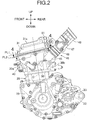
FIG. 2 is a left side view of an internal combustion engine. -
FIG. 3 is a right side view of the internal combustion engine. -
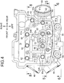
FIG. 4 is a view of a cylinder head viewed from a direction of the arrowed line 4-4 inFIG. 2 . -
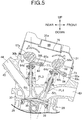
FIG. 5 is a sectional view taken along the line 5-5 ofFIG. 4 . -
FIG. 6 is a sectional view taken along the line 6-6 ofFIG. 4 . -
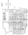
FIG. 7 a sectional view taken along the line 7-7 ofFIG. 2 . -
FIG. 8 is a longitudinal sectional side view of an engine body shown along the line 8-8 ofFIG. 4 . - An embodiment of the present invention will be explained referring to
FIG. 1 to FIG. 8 attached. Also, in the explanation described below, up, down, front, rear, left, and right are directions when viewed by an occupant riding a two-wheeled motor vehicle. - First, in
FIG. 1 , a body frame F of a two-wheeled motor vehicle that is for rough terrain travel includes ahead pipe 13, a pair of left and rightmain frames 14, adown frame 15, a pair of left and rightlower frames 16, a pair of left andright pivot frames 17, a pair of left andright seat rails 18, and a pair of left and rightrear frames 19, thehead pipe 13 steerably supporting afront fork 11 and asteering handlebar 12, thefront fork 11 pivotally supporting a front wheel WF, thesteering handlebar 12 having a bar shape, the pair of left and rightmain frames 14 extending downward to the rear from thehead pipe 13, thedown frame 15 extending downward to the rear at a steeper angle than themain frames 14 from thehead pipe 13, the pair of left and rightlower frames 16 being connected to the lower end portion of thedown frame 15 and extending rearward, the upper end portions of the pair of left andright pivot frames 17 being connected integrally to the rear end portions of themain frames 14 and extending downward, the rear end portions of the bothlower frames 16 being connected to the lower end portions of the pair of left andright pivot frames 17, the pair of left andright seat rails 18 being connected to the rear end portions of themain frames 14 and extending rearward, the pair of left and rightrear frames 19 extending upward to the rear with the front end portions of therear frames 19 being connected to the intermediate portions in the up-down direction of the bothpivot frames 17 and with the rear end portions of therear frames 19 being connected to thepivot frames 17. - On the body frame F, an
engine body 20 of a single cylinder DOHC-type internal combustion engine E is mounted so as to be disposed below themain frames 14 as seen in a side view. Anaxle 21 of a rear wheel WR is pivotally supported by the rear end portion of aswing arm 22, and the front end portion of thisswing arm 22 is supported by the lower portions of thepivot frames 17 in the body frame F through aspindle 23 in an up-down swingable manner. - A
link mechanism 25 is arranged between abracket 24 and theswing arm 22, thebracket 24 being arranged in the lower portion of thepivot frames 17 in the body frame F, and arear cushion unit 27 that extends in the up-down direction is arranged between alink member 26 and the upper portion of thepivot frames 17, thelink member 26 configuring a part of thelink mechanism 25. - A transmission not illustrated is stored within a
crankcase 28 that configures a part of theengine body 20, anoutput shaft 32 of the transmission protrudes sideways to the left from thecrankcase 28, and adrive chain 35 of an endless shape is wound around a drivingsprocket 33 and afollower sprocket 34, the drivingsprocket 33 being arranged on theoutput shaft 32, thefollower sprocket 34 being arranged on theaxle 21 of the rear wheel WR. - Also, a
fuel tank 36 is arranged above theengine body 20 and on the bothmain frames 14, and ariding seat 37 is disposed behind thefuel tank 36 so as to be supported by theseat rails 18. - With reference also to
FIG. 2 andFIG. 3 , theengine body 20 includes thecrankcase 28, acylinder body 29, acylinder head 30, and ahead cover 31, thecylinder body 29 being joined to the front side upper portion of thecrankcase 28 and extending upward, thecylinder head 30 being joined to the upper portion of thecylinder body 29, thehead cover 31 being joined to the upper portion of thecylinder head 30, and theengine body 20 is mounted on the body frame F with such attitude that a cylinder axis C is slightly tilted forward. Also, thecylinder head 30 and thehead cover 31 are joined to each other on a second imaginary plane PL2 that crosses the cylinder axis C with the forward tilt angle of the second imaginary plane PL2 slightly larger than that of a first imaginary plane PL1 that tilts so as to be positioned at an upper position as it goes to the rear along the vehicle longitudinal direction and is orthogonal to the cylinder axis C. - With reference also to
FIG. 4 , a pair of left andright exhaust ports 40 are arranged in afront wall 30a of thecylinder head 30, and anexhaust device 41 of the internal combustion engine E includes a pair ofexhaust pipes 42 and a pair of left andright mufflers 43 as shown clearly inFIG. 1 , the pair ofexhaust pipes 42 respectively coming around the left and right of theengine body 20 with the upstream side end portions of theexhaust pipes 42 being connected to theexhaust ports 40, the pair of left andright mufflers 43 being connected respectively to the downstream side ends of theexhaust pipes 42 and being disposed above the rear wheel WR. - From a
rear wall 30b of thecylinder head 30, an intakeconnection pipe portion 45 that configures asingle intake port 44 is protruded obliquely upward to the rear, and anintake device 46 of the internal combustion engine E includes athrottle body 47, aninsulator 48, aconnecting tube 49, and anair cleaner 50, thethrottle body 47 adjusting the air quantity that is supplied to theintake port 44, theinsulator 48 connecting the intakeconnection pipe portion 45 and thethrottle body 47 to each other, the downstream side end of the connectingtube 49 being connected to the upstream side end of thethrottle body 47, theair cleaner 50 being disposed below theriding seat 37 so that the upstream side end of the connectingtube 49 is connected to the air cleaner 50 (refer toFIG. 1 ). - With reference also to
FIG. 5 to FIG. 7 , acombustion chamber 39 is formed between thecylinder body 29 and thecylinder head 30, the top portion of apiston 38 facing thecombustion chamber 39, thepiston 38 being slidably fitted to thecylinder body 29, and aplug hole 55 is arranged so as to straddle between thecylinder head 30 and thehead cover 31 that is attached to thecylinder head 30, anignition plug 56 being to be inserted to theplug hole 55, theignition plug 56 being attached to thecylinder head 30 so that the tip end of theignition plug 56 faces the top portion of thecombustion chamber 39. - In the
cylinder head 30, a pair ofintake valves exhaust valves intake valves intake port 44 to thecombustion chamber 39, the pair ofexhaust valves combustion chamber 39 to theexhaust port 40, and avalve chamber 54 is formed between thecylinder head 30 and thehead cover 31, thevalve chamber 54 storing avalve train 53 that openably/closably drives theintake valves exhaust valves - The
valve train 53 includes an intake-side camshaft 57 and an exhaust-side camshaft 58, intake-side rocker arms side rocker arms side camshaft 57 and the exhaust-side camshaft 58 extending in parallel to each other in the vehicle width direction at positions that are apart from each other in the vehicle longitudinal direction and being disposed at positions that sandwich theplug hole 55 between the intake-side camshaft 57 and the exhaust-side camshaft 58, the paired intake-side rocker arms side camshaft 57 and theintake valves intake valves side rocker arms side camshaft 58 and theexhaust valves exhaust valves - The
intake valves plug hole 55 in the vehicle longitudinal direction so as to be arrayed in the direction along the axis of the intake-side camshaft 57, namely, the vehicle width direction, theexhaust valves plug hole 55 in the vehicle longitudinal direction so as to be arrayed in the direction along the axis of the exhaust-side camshaft 58, namely, the vehicle width direction, and theintake valves exhaust valves plug hole 55. - The intake-
side camshaft 57 and the exhaust-side camshaft 58 are rotatably supported by ashaft support portion 30c and acam holder 61, theshaft support portion 30c being integrally arranged in thecylinder head 30, thecam holder 61 being fastened to theshaft support portion 30c by a plurality of, for example, eight camholder attaching bolts 62. - The
cam holder 61 is formed so as to integrally include a left-siderotation support portion 61a, a right-siderotation support portion 61b, arear connection portion 61c, and afront connection portion 61d, the left-siderotation support portion 61a extending in the vehicle longitudinal direction so as to rotatably support a portion on the left side in the vehicle width direction of the intake-side camshaft 57 and the exhaust-side camshaft 58 between theshaft support portion 30c and the left-siderotation support portion 61a, the right-siderotation support portion 61b extending in the vehicle longitudinal direction so as to rotatably support a portion on the right side in the vehicle width direction of the intake-side camshaft 57 and the exhaust-side camshaft 58 between theshaft support portion 30c and the right-siderotation support portion 61b and being disposed on the right side in the vehicle width direction of the left-siderotation support portion 61a, therear connection portion 61c connecting between rear portions along the vehicle longitudinal direction of the left-siderotation support portion 61a and the right-siderotation support portion 61b, therear connection portion 61c covering the intake-side camshaft 57, thefront connection portion 61d connecting between front portions along the vehicle longitudinal direction of the left-siderotation support portion 61a and the right-siderotation support portion 61b, thefront connection portion 61d covering the exhaust-side camshaft 58. - One
intake valve 51L out of the pair ofintake valves rotation support portion 61a and below the intake-side camshaft 57, and oneexhaust valve 52L out of the pair ofexhaust valves rotation support portion 61a and below the exhaust-side camshaft 58. Also, theother intake valve 51R is disposed between the left-siderotation support portion 61a and the right-siderotation support portion 61b and below the intake-side camshaft 57, and theother exhaust valve 52R is disposed between the left-siderotation support portion 61a and the right-siderotation support portion 61b and below the exhaust-side camshaft 58. - The intake-
side rocker arm 59L is formed so as to include a firstvalve connection portion 64a and afirst support portion 65a at opposite ends, the firstvalve connection portion 64a being operatively connected with theintake valve 51L, thefirst support portion 65a being rockably supported by theshaft support portion 30c of thecylinder head 30, the intake-side rocker arm 59R is formed so as to include a secondvalve connection portion 64b and asecond support portion 65b at opposite ends, the secondvalve connection portion 64b being operatively connected with theintake valve 51R, thesecond support portion 65b being rockably supported by theshaft support portion 30c, the exhaust-side rocker arm 60L is formed so as to include a thirdvalve connection portion 64c and athird support portion 65c at opposite ends, the thirdvalve connection portion 64c being operatively connected with theexhaust valve 52L, thethird support portion 65c being rockably supported by theshaft support portion 30c and the exhaust-side rocker arm 60R is formed so as to include a fourthvalve connection portion 64d and afourth support portion 65d at opposite ends, the fourthvalve connection portion 64d being operatively connected with theexhaust valve 52R, thefourth support portion 65d being rockably supported by theshaft support portion 30c. - The first to fourth
valve connection portions 64a to 64d are formed so as to abut against theintake valves exhaust valves valves side cams 57a that are arranged in the intake-side camshaft 57 slidably contacts with the intake-side rocker arms valve connection portions side cams 58a that are arranged in the exhaust-side camshaft 58 slidably contacts with the exhaust-side rocker arms valve connection portions - As clearly shown in
FIG. 7 , the first andsecond support portions side rocker arms side rocker arms side rocker arms plug hole 55 and between theintake valves exhaust valves side camshafts 57, 58 (the vehicle longitudinal direction), and the third andfourth support portions side rocker arms side rocker arms side rocker arms intake valves exhaust valves side camshafts 57, 58 (the vehicle longitudinal direction). - Also, as clearly shown in
FIG. 5 , thefirst support portion 65a of one intake-side rocker arm 59L out of the one pair of the intake-side rocker arms side camshaft 57 and including the operation axes of theintake valves side camshaft 58 and including the operation axes of theexhaust valves first support portion 65a, thesecond support portions 65b of the other intake-side rocker arm 59R out of the one pair of the intake-side rocker arms fourth support portions side rocker arms - In other words, the
first support portion 65a and thesecond support portion 65b are disposed inslits shaft support portion 30c of thecylinder head 30 forward in the vehicle longitudinal direction of the intake-side camshaft 57, and are rockably supported respectively by thecylinder head 30 through first andsecond rocker shafts shaft support portion 30c. Also, thethird support portion 65c and thefourth support portion 65d are disposed inslits shaft support portion 30c of thecylinder head 30 forward in the vehicle longitudinal direction of the exhaust-side camshaft 58, and are rockably supported by thecylinder head 30 through a singlethird rocker shaft 73 that is attached to theshaft support portion 30c. - A distance between the first and second
valve connection portions side rocker arms second support portions FIG. 7 , a distance L1 between the center portions in the width direction of the first and secondvalve connection portions second support portions valve connection portions side rocker arms fourth support portions FIG. 7 , a distance L2 between the center portions in the width direction of the third and fourthvalve connection portions fourth support portions side rocker arms intake valves second support portions side rocker arms exhaust valves fourth support portions - In the meantime, the intake-side rocker arm 59L and the exhaust-side rocker arm 60R have a same shape and are commonalized, the intake-side rocker arm 59L being disposed on one side (the left side in the vehicle direction in the present embodiment) in the direction along the axis of the intake-side camshaft 57 out of the pair of intake-side rocker arms 59L, 59R, the exhaust-side rocker arm 60R being disposed on the other side (the right side in the vehicle direction in the present embodiment) in the direction along the axis of the exhaust-side camshaft 58 out of the pair of exhaust-side rocker arms 60L, 60R, and the intake-side rocker arm 59R and the exhaust-side rocker arm 60L have a same shape and are commonalized, the intake-side rocker arm 59R being disposed on the other side (the right side in the vehicle direction in the present embodiment) in the direction along the axis of the intake-side camshaft 57 out of the pair of intake-side rocker arms 59L, 59R, the exhaust-side rocker arm 60L being disposed on the one side (the left side in the vehicle direction in the present embodiment) in the direction along the axis of the exhaust-side camshaft 58 out of the pair of exhaust-side rocker arms 60L, 60R.
- In other words, the intake-
side rocker arms side rocker arms fourth support portions side rocker arm 59L and the exhaust-side rocker arm 60R, second support holes 84 having a same inside diameter are respectively formed in the second andthird support portions side rocker arm 59R and the exhaust-side rocker arm 60L so that the inside dimeter becomes different from that of thefirst support hole 83, and the inside diameter of thefirst support hole 83 is set smaller than the inside diameter of thesecond support hole 84. - Therefore, an outside diameter d1 of the
first rocker shaft 71L that is inserted to thefirst support hole 83 of thefirst support portion 65a is set smaller than an outside diameter d2 of thesecond rocker shaft 71R that is inserted to thesecond support hole 84 of thesecond support portion 65b (dl<d2). Also, the singlethird rocker shaft 73 that is common to the third andfourth support portions third rocker shaft 73 which is inserted to thethird support portion 65c and a portion of thethird rocker shaft 73 which is inserted to thefourth support portion 65d are made different in the outside diameter, and thethird rocker shaft 73 is formed so that asmall diameter portion 73a and alarge diameter portion 73b are connected to each other coaxially, thesmall diameter portion 73a having the outside diameter d1 same as that of thefirst rocker shaft 71L so as to be inserted to thefirst support hole 83 of thefourth support portion 65d, thelarge diameter portion 73b having the outside diameter d2 same as that of thesecond rocker shaft 71R so as to be inserted to thesecond support hole 84 of thethird support portion 65c. - The
plug hole 55 is configured with a plug bore 66, a cam holder sidetubular portion 67, a head cover sidetubular portion 68, and a throughhole 69, the plug bore 66 being formed in theshaft support portion 30c of thecylinder head 30, the cam holder sidetubular portion 67 being arranged integrally to the left-siderotation support portion 61a of thecam holder 61 so as to be connected to the plug bore 66, the head cover sidetubular portion 68 being arranged integrally to thehead cover 31 with agasket 74 being interposed between the upper end of the cam holder sidetubular portion 67, the throughhole 69 being arranged in aceiling wall 31a of thehead cover 31 so as to be connected to the head cover sidetubular portion 68. - In a part of the
plug hole 55, along hole portion 55a is formed, thelong hole portion 55a being formed long in the direction orthogonal to the axes of the intake-side and exhaust-side camshafts long hole portion 55a is formed by that the cam holder sidetubular portion 67 and the head cover sidetubular portion 68 are made have a section with an elliptical shape extending long in the direction orthogonal to the axes of the intake-side and exhaust-side camshafts step portion 67a that faces to thehead cover 31 side is formed within the cam holder sidetubular portion 67. - Within the
long hole portion 55a, two camholder attaching bolts 62 out of the eight camholder attaching bolts 62 for fastening thecam holder 61 to theshaft support portion 30c of thecylinder head 30 are disposed so as to abut against and engage with thestep portion 67a. - A
breather plate 79 is fastened to thehead cover 31, abreather chamber 80 is formed between thebreather plate 79 and thehead cover 31 so as to surround thelong hole portion 55a of theplug hole 55, and a lead outpipe 81 is attached to thehead cover 31 in order to lead out gas from thebreather chamber 80 to theair cleaner 50 side in theintake device 46. - With reference also to
FIG. 8 ,follower sprockets side camshaft 57 and the exhaust-side camshaft 58 from the right-siderotation support portion 61b of thecam holder 61, and acam chain 77 is wound around thefollower sprockets side camshafts cam chain chamber 78 for allowing thecam chain 77 to travel is formed in thecrankcase 28, thecylinder body 29, and thecylinder head 30. - Watching
FIG. 7 , atubular portion 85 for forming at least a part (a part in the present embodiment) of theplug hole 55 is arranged integrally in theshaft support portion 30c of thecylinder head 30, and the first andsecond rocker shafts second support portions plug hole 55 in the direction along the axes of the intake-side and the exhaust-side camshafts tubular portion 85, end portions on theplug hole 55 side of the first andsecond rocker shafts second rocker shafts first rocker shaft 71L in the present embodiment) is prevented by the inner end closing portion of at least one of the pair of support recesses 86, 87 (thesupport recess 86 in the present embodiment) and an anti-come-off plug 88 that is attached to thecylinder head 30 so as to abut, from the side opposite to theplug hole 55, against therocker shaft 71L which is at least one of the first andsecond rocker shafts off plug 88 is a bolt in the present embodiment, and the anti-come-off plug 88 that is a bolt may be formed so as to be integral with the first rocker shaft 71. - In the meantime, a part of the
cam chain chamber 78 is formed in thecylinder head 30, the part of thecam chain chamber 78 being disposed so that the other rocker shaft of the first andsecond rocker shafts second rocker shaft 71R is sandwiched between thecam chain chamber 78 and theplug hole 55, and a first anti-come-off pin 90 penetrates thecam holder 61, is press-fitted into thecylinder head 30 so as to prevent axial movement of thesecond rocker shaft 72R, and is thereby attached to thecylinder head 30, the first anti-come-off pin 90 engaging with a firstannular locking groove 89 that is formed on the outer surface of the intermediate portion of thesecond rocker shaft 71R. - A second
annular locking groove 92 is formed in thelarge diameter portion 73b of thethird rocker shaft 73, a second anti-come-off pin 91 penetrates thecam holder 61 and is press-fitted into thecylinder head 30, the second anti-come-off pin 91 engaging with the secondannular locking groove 92 and preventing axial movement of thethird rocker shaft 73, and acap 93 is screwed into the left side wall of thecylinder head 30, thecap 93 abutting against the end portion of thethird rocker shaft 73 on the side opposite to thecam chain chamber 78. Thecap 93 is a bolt in the present embodiment, thecap 93 that is a bolt may be formed so as to be integral with thethird rocker shaft 73, and in this case, the secondannular locking groove 92 and the second anti-come-off pin 91 become unnecessary. - Next, the operation of the present embodiment will be explained. Two pairs of the rocker arms, namely, the pair of intake-
side rocker arms side rocker arms side camshaft 57 and the exhaust-side camshaft 58 and theintake valves exhaust valves side camshaft 57 and the exhaust-side camshaft 58 being disposed in parallel to each other with theplug hole 55 interposed therebetween, theintake valves exhaust valves plug hole 55 and are arrayed by pairs in the axial direction of the intake-side and exhaust-side camshafts second support portions side rocker arms plug hole 55 and between theintake valves exhaust valves side camshafts fourth support portions side rocker arms intake valves exhaust valves side camshafts side rocker arms side rocker arms intake valves exhaust valves side camshafts respective rocker arms plug hole 55, and downsizing of thecylinder head 30 can be achieved. - Also, the distance between the first and second
valve connection portions side rocker arms second support portions valve connection portions side rocker arms fourth support portions intake valves exhaust valves side camshafts fourth support portions intake valves exhaust valves side camshafts cylinder head 30. - Also, the intake-
side rocker arm 59L, on one side along the axes of the intake-side and exhaust-side camshafts side rocker arms side rocker arm 60R, on the other side along the axes of the intake-side and exhaust-side camshafts side rocker arms side rocker arm 59R, on the other side along the axes of the intake-side and exhaust-side camshafts side rocker arms side rocker arm 60L, on one side along the axes of the intake-side and exhaust-side camshafts side rocker arms side rocker arms intake valves side rocker arms exhaust valves rocker arms - Also, the inside diameter of the
first support hole 83 and the inside diameter of thesecond support hole 84 are set different from each other, thefirst support hole 83 being formed in the first andfourth support portions side rocker arm 59L and the exhaust-side rocker arm 60R out of two pairs of therocker arms second support hole 84 being formed in the second andthird support portions side rocker arm 59R and the exhaust-side rocker arm 60L. Therefore, while achieving downsizing of thecylinder head 30, assembling position of each of therocker arms - Also, the
tubular portion 85 forming at least a part of theplug hole 55 is arranged integrally in thecylinder head 30, the first andsecond rocker shafts second support portions plug hole 55 in the direction along the axes of the intake-side and exhaust-side camshafts tubular portion 85, end portions on theplug hole 55 side of the first andsecond rocker shafts first rocker shaft 71L that is at least one of the first andsecond rocker shafts off plug 88 and the inner end closing portion of thesupport recess 86 which is at least one of the pair of support recesses 86, 87, the anti-come-off plug 88 being attached to thecylinder head 30 so as to abut against at least therocker shaft 71L from the side opposite to theplug hole 55. Therefore, axial movement of thefirst rocker shaft 71L can be prevented utilizing thetubular portion 85, and assembling efficiency of thefirst rocker shaft 71L and productivity of the internal combustion engine E can be thereby improved. - Also, a part of the
cam chain chamber 78 is formed in thecylinder head 30, thecam chain chamber 78 being disposed so that thesecond rocker shaft 71R that is the other of the first andsecond rocker shafts cam chain chamber 78 and theplug hole 55, and the first anti-come-off pin 90 is attached to thecylinder head 30, the first anti-come-off pin 90 engaging with the firstannular locking groove 89 that is formed on the outer surface of the intermediate portion of thesecond rocker shaft 71R. Therefore, it is not required to reserve a special space between theplug hole 55 and thecam chain chamber 78, and downsizing of thecylinder head 30 can be thereby achieved, the special space being for preventing coming-off of thesecond rocker shaft 71R. - Also, the single
third rocker shaft 73 which is common to the third andfourth support portions third rocker shaft 73 which is inserted to thethird support portion 65c and a portion of thethird rocker shaft 73 which is inserted to thefourth support portion 65d are made different in the outside diameter. Therefore, such event can be coped with that the inside diameters of the first and second support holes 83, 84 formed in the third andfourth support portions fourth support portions third rocker shaft 73 is simplified, and assembling efficiency is improved which can contribute to improvement of the productivity. - Although the embodiment of the present invention has been explained above, the present invention is not limited to the embodiment described above, and various design changes can be effected without departing from the gist of the present invention.
- For example, although explanation was made with respect to the single-cylinder DOHC-type internal combustion engine E in the embodiment described above, it is also possible to apply the present invention to each cylinder of a multi-cylinder DOHC-type internal combustion engine.
Claims (7)
- A DOHC-type internal combustion engine, in which an intake-side camshaft (57) and an exhaust-side camshaft (58) are disposed in parallel to each other with a plug hole (55) interposed therebetween, an ignition plug (56) being to be inserted into the plug hole (55), a pair of intake valves (51L, 51R) and a pair of exhaust valves (52L, 52R) are disposed around the plug hole (55), the intake valves (51L, 51R) being arrayed in a direction along an axis of the intake-side camshaft (57), the exhaust valves (52L, 52R) being arrayed in a direction along an axis of the exhaust-side camshaft (58), two pairs of rocker arms (59L, 59R; 60L, 60R) are respectively interposed between the intake-side and exhaust-side camshafts (57, 58) and the intake valves (51L, 51R) and the exhaust valves (52L, 52R), the two pairs of rocker arms (59L, 59R; 60L, 60R) respectively corresponding to the intake valves (51L, 51R) and the exhaust valves (52L, 52R) while respectively including support portions (65a, 65b, 65c, 65d) and valve connection portions (64a, 64b, 64c, 64d), the support portions (65a, 65b, 65c, 65d) being rockably supported by a cylinder head (30), the valve connection portions (64a, 64b, 64c, 64d) being operatively connected respectively with the intake valves (51L, 51R) and the exhaust valves (52L, 52R),
wherein the first and second support portions (65a, 65b) of one pair of the rocker arms (59L, 59R) out of the support portions (65a to 65d) are disposed between the intake valves (51L, 51R) and the exhaust valves (52L, 52R) in a direction orthogonal to the axes of the intake-side and exhaust-side camshafts (57, 58) and around the plug hole (55), and
the third and fourth support portions (65c, 65d) of an other pair of the rocker arms (60L, 60R) out of the support portions (65a to 65d) are disposed outside a region between the intake valves (51L, 51R) and the exhaust valves (52L, 52R) in the direction orthogonal to the axes of the intake-side and exhaust-side camshafts (57, 58). - The DOHC-type internal combustion engine according to claim 1,
wherein a distance between the first and second valve connection portions (64a, 64b) of the one pair of rocker arms (59L, 59R) is set shorter than a distance between the first and second support portions (65a, 65b), and
a distance between the third and fourth valve connection portions (64c, 64d) of the other pair of the rocker arms (60L, 60R) is set longer than a distance between the third and fourth support portions (65c, 65d). - The DOHC-type internal combustion engine according to claim 2,
wherein the rocker arm (59L), on one side along the axes of the intake-side and exhaust-side camshafts (57, 58) out of the one pair of the rocker arms (59L, 59R), and the rocker arm (60R), on the other side along the axes of the intake-side and exhaust-side camshafts (57, 58) out of the other pair of the rocker arms (60L, 60R), have a same shape and are commonalized, and
the rocker arm (59R), on the other side along the axes of the intake-side and exhaust-side camshafts (57, 58) out of the one pair of the rocker arms (59L, 59R), and the rocker arm (60L), on one side along the axes of the intake-side and exhaust-side camshafts (57, 58) out of the other pair of the rocker arms (60L, 60R), have a same shape and are commonalized. - The DOHC-type internal combustion engine according to claim 3,
wherein out of the two pairs of the rocker arms (59L, 59R; 60L, 60R) each pair having two kinds of shapes, an inside diameter of a support hole (83), which is formed in the first and fourth support portions (65a, 65d) of one kind of the rocker arms (59L, 60R), and an inside diameter of a support hole (84), which is formed in the second and third support portions (65b, 65c) of an other kind of the rocker arms (59R, 60L), are set different from each other. - The DOHC-type internal combustion engine according to claim 4,
wherein a tubular portion (85) is arranged integrally in the cylinder head (30), the tubular portion (85) forming at least a part of the plug hole (55),
first and second rocker shafts (71L, 71R) are disposed on opposite sides of the plug hole (55) in a direction along the axes of the intake-side and exhaust-side camshafts (57, 58), the first and second rocker shafts (71L, 71R) supporting the first and second support portions (65a, 65b) individually,
a pair of support recesses (86, 87) are formed in the tubular portion (85), end portions on the plug hole (55) side of the first and second rocker shafts (71L, 71R) being fitted to the pair of support recesses (86, 87) respectively, and
axial movement of at least one (71L) of the first and second rocker shafts (71L, 71R) is prevented by an anti-come-off plug (88) and an inner end closing portion of at least one (86) of the pair of support recesses (86, 87), the anti-come-off plug (88) being attached to the cylinder head (30) so as to abut, from a side opposite to the plug hole (55), against at least the one (71L) of the first and second rocker shafts (71L, 71R). - The DOHC-type internal combustion engine according to claim 5,
wherein a part of a cam chain chamber (78) is formed in the cylinder head (30), the cam chain chamber (78) being disposed so that an other (71R) of the first and second rocker shafts (71L, 71R) is sandwiched between the cam chain chamber (78) and the plug hole (55), and
an anti-come-off pin (90) is attached to the cylinder head (30), the anti-come-off pin (90) engaging with an annular locking groove (89) that is formed on an outer surface of an intermediate portion of the other rocker shaft (71R). - The DOHC-type internal combustion engine according to any one of claims 4 to 6,
wherein a single third rocker shaft (73) is formed to have a step so that a portion of the third rocker shaft (73) which is inserted to the third support portion (65c) and a portion of the third rocker shaft (73) which is inserted to the fourth support portion (65d) are made different in an outside diameter, the third rocker shaft (73) being common to the third and fourth support portions (65c, 65d).
Applications Claiming Priority (1)
| Application Number | Priority Date | Filing Date | Title |
|---|---|---|---|
| JP2017054153A JP6839576B2 (en) | 2017-03-21 | 2017-03-21 | DOHC type internal combustion engine |
Publications (2)
| Publication Number | Publication Date |
|---|---|
| EP3379044A1 true EP3379044A1 (en) | 2018-09-26 |
| EP3379044B1 EP3379044B1 (en) | 2019-11-13 |
Family
ID=61074355
Family Applications (1)
| Application Number | Title | Priority Date | Filing Date |
|---|---|---|---|
| EP18153791.1A Active EP3379044B1 (en) | 2017-03-21 | 2018-01-29 | Dohc-type internal combustion engine |
Country Status (3)
| Country | Link |
|---|---|
| US (1) | US10309265B2 (en) |
| EP (1) | EP3379044B1 (en) |
| JP (1) | JP6839576B2 (en) |
Citations (7)
| Publication number | Priority date | Publication date | Assignee | Title |
|---|---|---|---|---|
| EP0258061A1 (en) * | 1986-08-27 | 1988-03-02 | Honda Giken Kogyo Kabushiki Kaisha | Valve operating apparatus in an internal combustion engine |
| DE4018586A1 (en) * | 1990-06-09 | 1991-12-12 | Audi Ag | IC-engine with twin camshaft - has rocker arms mounted on pin aligned parallel to camshafts |
| EP2615267A2 (en) * | 2012-01-13 | 2013-07-17 | Suzuki Motor Corporation | Valve train mechanism of internal combustion engine |
| JP2015094238A (en) | 2013-11-08 | 2015-05-18 | 本田技研工業株式会社 | Internal combustion engine holder structure |
| US20160265396A1 (en) * | 2015-02-27 | 2016-09-15 | GM Global Technology Operations LLC | Exhaust valve and an engine assembly including the exhaust valve having a pressure relief apparatus |
| US20160341079A1 (en) * | 2014-02-28 | 2016-11-24 | Mazda Motor Corporation | Device for controlling valve timing of engine |
| EP3301283A1 (en) * | 2016-09-29 | 2018-04-04 | Honda Motor Co., Ltd. | Single cylinder internal combustion engine |
Family Cites Families (13)
| Publication number | Priority date | Publication date | Assignee | Title |
|---|---|---|---|---|
| DE2809157A1 (en) * | 1978-03-03 | 1979-09-06 | Daimler Benz Ag | CYLINDER HEAD FOR A MIXED COMPRESSING COMBUSTION MACHINE |
| JPS6079141A (en) * | 1983-10-04 | 1985-05-04 | Honda Motor Co Ltd | Cylinder head of DOHC type 4-stroke internal combustion engine |
| US4617881A (en) * | 1985-03-29 | 1986-10-21 | Yamaha Hatsudoki Kabushiki Kaisha | Actuating mechanism for multiple valve internal combustion engine |
| DE69025368T2 (en) * | 1989-09-28 | 1996-07-25 | Mazda Motor | Multi-valve internal combustion engine |
| JP2002276523A (en) * | 2001-03-21 | 2002-09-25 | Yamaha Motor Co Ltd | Plug pipe mounting structure for internal combustion engine |
| US20060266315A1 (en) * | 2005-05-31 | 2006-11-30 | Yamaha Hatsudoki Kabushiki Kaisha | Valve actuating system for reciprocating machine |
| JP4265573B2 (en) * | 2005-06-09 | 2009-05-20 | 三菱自動車工業株式会社 | Variable valve operating device for internal combustion engine |
| JP4574521B2 (en) * | 2005-11-16 | 2010-11-04 | 川崎重工業株式会社 | Twin cam engine |
| DE102007032638A1 (en) * | 2007-07-11 | 2009-01-15 | Bayerische Motoren Werke Aktiengesellschaft | Internal combustion engine with a crankshaft and at least one cylinder head and motor vehicle with such an internal combustion engine |
| JP5966999B2 (en) * | 2013-03-29 | 2016-08-10 | マツダ株式会社 | Multi-cylinder engine controller |
| JP6123575B2 (en) * | 2013-08-22 | 2017-05-10 | マツダ株式会社 | Multi-cylinder engine controller |
| JP6135580B2 (en) * | 2014-03-31 | 2017-05-31 | マツダ株式会社 | Engine control device |
| JP6020770B2 (en) * | 2014-08-29 | 2016-11-02 | マツダ株式会社 | Engine control device |
-
2017
- 2017-03-21 JP JP2017054153A patent/JP6839576B2/en active Active
-
2018
- 2018-01-25 US US15/879,858 patent/US10309265B2/en active Active
- 2018-01-29 EP EP18153791.1A patent/EP3379044B1/en active Active
Patent Citations (7)
| Publication number | Priority date | Publication date | Assignee | Title |
|---|---|---|---|---|
| EP0258061A1 (en) * | 1986-08-27 | 1988-03-02 | Honda Giken Kogyo Kabushiki Kaisha | Valve operating apparatus in an internal combustion engine |
| DE4018586A1 (en) * | 1990-06-09 | 1991-12-12 | Audi Ag | IC-engine with twin camshaft - has rocker arms mounted on pin aligned parallel to camshafts |
| EP2615267A2 (en) * | 2012-01-13 | 2013-07-17 | Suzuki Motor Corporation | Valve train mechanism of internal combustion engine |
| JP2015094238A (en) | 2013-11-08 | 2015-05-18 | 本田技研工業株式会社 | Internal combustion engine holder structure |
| US20160341079A1 (en) * | 2014-02-28 | 2016-11-24 | Mazda Motor Corporation | Device for controlling valve timing of engine |
| US20160265396A1 (en) * | 2015-02-27 | 2016-09-15 | GM Global Technology Operations LLC | Exhaust valve and an engine assembly including the exhaust valve having a pressure relief apparatus |
| EP3301283A1 (en) * | 2016-09-29 | 2018-04-04 | Honda Motor Co., Ltd. | Single cylinder internal combustion engine |
Also Published As
| Publication number | Publication date |
|---|---|
| US20180274394A1 (en) | 2018-09-27 |
| JP2018155214A (en) | 2018-10-04 |
| US10309265B2 (en) | 2019-06-04 |
| EP3379044B1 (en) | 2019-11-13 |
| JP6839576B2 (en) | 2021-03-10 |
Similar Documents
| Publication | Publication Date | Title |
|---|---|---|
| EP3301283B1 (en) | Single cylinder internal combustion engine | |
| TWI322852B (en) | ||
| KR100921873B1 (en) | Motorcycle | |
| EP2669482B1 (en) | Intake system for internal combustion engine | |
| US10151238B2 (en) | Internal combustion engine for saddle-ride type vehicle | |
| EP3379044B1 (en) | Dohc-type internal combustion engine | |
| US8887678B2 (en) | Lubricating structure for internal combustion engine | |
| AU2017213525B2 (en) | Saddle-ride type vehicle | |
| JP6714648B2 (en) | Internal combustion engine for saddle type vehicles | |
| US10316701B2 (en) | Overhead valve actuation mechanism for engine | |
| JP6680822B2 (en) | Intake structure of internal combustion engine for saddle type vehicle | |
| JP2019052649A (en) | Internal combustion engine | |
| JP6714647B2 (en) | Secondary air introduction device for internal combustion engine for saddle type vehicle | |
| JP6818065B2 (en) | engine | |
| JP2016176383A (en) | Cylinder injection type internal combustion engine | |
| JP6256068B2 (en) | Gear support structure for cam gear train mechanism of motorcycle | |
| JP2013155647A (en) | Cam housing structure for three-dimensional cam | |
| WO2019035389A1 (en) | Internal-combustion engine and saddle-type vehicle | |
| JPH11324788A (en) | Motorcycle engine |
Legal Events
| Date | Code | Title | Description |
|---|---|---|---|
| PUAI | Public reference made under article 153(3) epc to a published international application that has entered the european phase |
Free format text: ORIGINAL CODE: 0009012 |
|
| STAA | Information on the status of an ep patent application or granted ep patent |
Free format text: STATUS: REQUEST FOR EXAMINATION WAS MADE |
|
| 17P | Request for examination filed |
Effective date: 20180129 |
|
| AK | Designated contracting states |
Kind code of ref document: A1 Designated state(s): AL AT BE BG CH CY CZ DE DK EE ES FI FR GB GR HR HU IE IS IT LI LT LU LV MC MK MT NL NO PL PT RO RS SE SI SK SM TR |
|
| AX | Request for extension of the european patent |
Extension state: BA ME |
|
| RIC1 | Information provided on ipc code assigned before grant |
Ipc: F01L 1/18 20060101ALI20190516BHEP Ipc: F01L 1/053 20060101AFI20190516BHEP Ipc: F01L 1/02 20060101ALI20190516BHEP Ipc: F02D 41/00 20060101ALI20190516BHEP |
|
| GRAP | Despatch of communication of intention to grant a patent |
Free format text: ORIGINAL CODE: EPIDOSNIGR1 |
|
| STAA | Information on the status of an ep patent application or granted ep patent |
Free format text: STATUS: GRANT OF PATENT IS INTENDED |
|
| INTG | Intention to grant announced |
Effective date: 20190621 |
|
| GRAS | Grant fee paid |
Free format text: ORIGINAL CODE: EPIDOSNIGR3 |
|
| GRAA | (expected) grant |
Free format text: ORIGINAL CODE: 0009210 |
|
| STAA | Information on the status of an ep patent application or granted ep patent |
Free format text: STATUS: THE PATENT HAS BEEN GRANTED |
|
| AK | Designated contracting states |
Kind code of ref document: B1 Designated state(s): AL AT BE BG CH CY CZ DE DK EE ES FI FR GB GR HR HU IE IS IT LI LT LU LV MC MK MT NL NO PL PT RO RS SE SI SK SM TR |
|
| REG | Reference to a national code |
Ref country code: CH Ref legal event code: EP Ref country code: AT Ref legal event code: REF Ref document number: 1201874 Country of ref document: AT Kind code of ref document: T Effective date: 20191115 |
|
| REG | Reference to a national code |
Ref country code: DE Ref legal event code: R096 Ref document number: 602018001126 Country of ref document: DE |
|
| REG | Reference to a national code |
Ref country code: IE Ref legal event code: FG4D |
|
| REG | Reference to a national code |
Ref country code: NL Ref legal event code: MP Effective date: 20191113 |
|
| REG | Reference to a national code |
Ref country code: LT Ref legal event code: MG4D |
|
| PG25 | Lapsed in a contracting state [announced via postgrant information from national office to epo] |
Ref country code: FI Free format text: LAPSE BECAUSE OF FAILURE TO SUBMIT A TRANSLATION OF THE DESCRIPTION OR TO PAY THE FEE WITHIN THE PRESCRIBED TIME-LIMIT Effective date: 20191113 Ref country code: BG Free format text: LAPSE BECAUSE OF FAILURE TO SUBMIT A TRANSLATION OF THE DESCRIPTION OR TO PAY THE FEE WITHIN THE PRESCRIBED TIME-LIMIT Effective date: 20200213 Ref country code: LT Free format text: LAPSE BECAUSE OF FAILURE TO SUBMIT A TRANSLATION OF THE DESCRIPTION OR TO PAY THE FEE WITHIN THE PRESCRIBED TIME-LIMIT Effective date: 20191113 Ref country code: PL Free format text: LAPSE BECAUSE OF FAILURE TO SUBMIT A TRANSLATION OF THE DESCRIPTION OR TO PAY THE FEE WITHIN THE PRESCRIBED TIME-LIMIT Effective date: 20191113 Ref country code: PT Free format text: LAPSE BECAUSE OF FAILURE TO SUBMIT A TRANSLATION OF THE DESCRIPTION OR TO PAY THE FEE WITHIN THE PRESCRIBED TIME-LIMIT Effective date: 20200313 Ref country code: GR Free format text: LAPSE BECAUSE OF FAILURE TO SUBMIT A TRANSLATION OF THE DESCRIPTION OR TO PAY THE FEE WITHIN THE PRESCRIBED TIME-LIMIT Effective date: 20200214 Ref country code: NO Free format text: LAPSE BECAUSE OF FAILURE TO SUBMIT A TRANSLATION OF THE DESCRIPTION OR TO PAY THE FEE WITHIN THE PRESCRIBED TIME-LIMIT Effective date: 20200213 Ref country code: LV Free format text: LAPSE BECAUSE OF FAILURE TO SUBMIT A TRANSLATION OF THE DESCRIPTION OR TO PAY THE FEE WITHIN THE PRESCRIBED TIME-LIMIT Effective date: 20191113 Ref country code: SE Free format text: LAPSE BECAUSE OF FAILURE TO SUBMIT A TRANSLATION OF THE DESCRIPTION OR TO PAY THE FEE WITHIN THE PRESCRIBED TIME-LIMIT Effective date: 20191113 Ref country code: NL Free format text: LAPSE BECAUSE OF FAILURE TO SUBMIT A TRANSLATION OF THE DESCRIPTION OR TO PAY THE FEE WITHIN THE PRESCRIBED TIME-LIMIT Effective date: 20191113 |
|
| PGFP | Annual fee paid to national office [announced via postgrant information from national office to epo] |
Ref country code: DE Payment date: 20200130 Year of fee payment: 3 |
|
| PG25 | Lapsed in a contracting state [announced via postgrant information from national office to epo] |
Ref country code: RS Free format text: LAPSE BECAUSE OF FAILURE TO SUBMIT A TRANSLATION OF THE DESCRIPTION OR TO PAY THE FEE WITHIN THE PRESCRIBED TIME-LIMIT Effective date: 20191113 Ref country code: HR Free format text: LAPSE BECAUSE OF FAILURE TO SUBMIT A TRANSLATION OF THE DESCRIPTION OR TO PAY THE FEE WITHIN THE PRESCRIBED TIME-LIMIT Effective date: 20191113 Ref country code: IS Free format text: LAPSE BECAUSE OF FAILURE TO SUBMIT A TRANSLATION OF THE DESCRIPTION OR TO PAY THE FEE WITHIN THE PRESCRIBED TIME-LIMIT Effective date: 20200313 |
|
| PG25 | Lapsed in a contracting state [announced via postgrant information from national office to epo] |
Ref country code: AL Free format text: LAPSE BECAUSE OF FAILURE TO SUBMIT A TRANSLATION OF THE DESCRIPTION OR TO PAY THE FEE WITHIN THE PRESCRIBED TIME-LIMIT Effective date: 20191113 |
|
| PGFP | Annual fee paid to national office [announced via postgrant information from national office to epo] |
Ref country code: FR Payment date: 20200123 Year of fee payment: 3 |
|
| PG25 | Lapsed in a contracting state [announced via postgrant information from national office to epo] |
Ref country code: EE Free format text: LAPSE BECAUSE OF FAILURE TO SUBMIT A TRANSLATION OF THE DESCRIPTION OR TO PAY THE FEE WITHIN THE PRESCRIBED TIME-LIMIT Effective date: 20191113 Ref country code: DK Free format text: LAPSE BECAUSE OF FAILURE TO SUBMIT A TRANSLATION OF THE DESCRIPTION OR TO PAY THE FEE WITHIN THE PRESCRIBED TIME-LIMIT Effective date: 20191113 Ref country code: RO Free format text: LAPSE BECAUSE OF FAILURE TO SUBMIT A TRANSLATION OF THE DESCRIPTION OR TO PAY THE FEE WITHIN THE PRESCRIBED TIME-LIMIT Effective date: 20191113 Ref country code: CZ Free format text: LAPSE BECAUSE OF FAILURE TO SUBMIT A TRANSLATION OF THE DESCRIPTION OR TO PAY THE FEE WITHIN THE PRESCRIBED TIME-LIMIT Effective date: 20191113 Ref country code: ES Free format text: LAPSE BECAUSE OF FAILURE TO SUBMIT A TRANSLATION OF THE DESCRIPTION OR TO PAY THE FEE WITHIN THE PRESCRIBED TIME-LIMIT Effective date: 20191113 |
|
| REG | Reference to a national code |
Ref country code: DE Ref legal event code: R097 Ref document number: 602018001126 Country of ref document: DE |
|
| REG | Reference to a national code |
Ref country code: AT Ref legal event code: MK05 Ref document number: 1201874 Country of ref document: AT Kind code of ref document: T Effective date: 20191113 |
|
| PG25 | Lapsed in a contracting state [announced via postgrant information from national office to epo] |
Ref country code: MC Free format text: LAPSE BECAUSE OF FAILURE TO SUBMIT A TRANSLATION OF THE DESCRIPTION OR TO PAY THE FEE WITHIN THE PRESCRIBED TIME-LIMIT Effective date: 20191113 Ref country code: SM Free format text: LAPSE BECAUSE OF FAILURE TO SUBMIT A TRANSLATION OF THE DESCRIPTION OR TO PAY THE FEE WITHIN THE PRESCRIBED TIME-LIMIT Effective date: 20191113 Ref country code: SK Free format text: LAPSE BECAUSE OF FAILURE TO SUBMIT A TRANSLATION OF THE DESCRIPTION OR TO PAY THE FEE WITHIN THE PRESCRIBED TIME-LIMIT Effective date: 20191113 |
|
| PLBE | No opposition filed within time limit |
Free format text: ORIGINAL CODE: 0009261 |
|
| STAA | Information on the status of an ep patent application or granted ep patent |
Free format text: STATUS: NO OPPOSITION FILED WITHIN TIME LIMIT |
|
| REG | Reference to a national code |
Ref country code: BE Ref legal event code: MM Effective date: 20200131 |
|
| 26N | No opposition filed |
Effective date: 20200814 |
|
| PG25 | Lapsed in a contracting state [announced via postgrant information from national office to epo] |
Ref country code: LU Free format text: LAPSE BECAUSE OF NON-PAYMENT OF DUE FEES Effective date: 20200129 |
|
| PG25 | Lapsed in a contracting state [announced via postgrant information from national office to epo] |
Ref country code: AT Free format text: LAPSE BECAUSE OF FAILURE TO SUBMIT A TRANSLATION OF THE DESCRIPTION OR TO PAY THE FEE WITHIN THE PRESCRIBED TIME-LIMIT Effective date: 20191113 Ref country code: BE Free format text: LAPSE BECAUSE OF NON-PAYMENT OF DUE FEES Effective date: 20200131 Ref country code: SI Free format text: LAPSE BECAUSE OF FAILURE TO SUBMIT A TRANSLATION OF THE DESCRIPTION OR TO PAY THE FEE WITHIN THE PRESCRIBED TIME-LIMIT Effective date: 20191113 |
|
| PG25 | Lapsed in a contracting state [announced via postgrant information from national office to epo] |
Ref country code: IE Free format text: LAPSE BECAUSE OF NON-PAYMENT OF DUE FEES Effective date: 20200129 |
|
| PGFP | Annual fee paid to national office [announced via postgrant information from national office to epo] |
Ref country code: IT Payment date: 20210131 Year of fee payment: 4 |
|
| REG | Reference to a national code |
Ref country code: DE Ref legal event code: R119 Ref document number: 602018001126 Country of ref document: DE |
|
| REG | Reference to a national code |
Ref country code: CH Ref legal event code: PL |
|
| PG25 | Lapsed in a contracting state [announced via postgrant information from national office to epo] |
Ref country code: FR Free format text: LAPSE BECAUSE OF NON-PAYMENT OF DUE FEES Effective date: 20210131 |
|
| PG25 | Lapsed in a contracting state [announced via postgrant information from national office to epo] |
Ref country code: LI Free format text: LAPSE BECAUSE OF NON-PAYMENT OF DUE FEES Effective date: 20210131 Ref country code: DE Free format text: LAPSE BECAUSE OF NON-PAYMENT OF DUE FEES Effective date: 20210803 Ref country code: CH Free format text: LAPSE BECAUSE OF NON-PAYMENT OF DUE FEES Effective date: 20210131 |
|
| PG25 | Lapsed in a contracting state [announced via postgrant information from national office to epo] |
Ref country code: TR Free format text: LAPSE BECAUSE OF FAILURE TO SUBMIT A TRANSLATION OF THE DESCRIPTION OR TO PAY THE FEE WITHIN THE PRESCRIBED TIME-LIMIT Effective date: 20191113 Ref country code: MT Free format text: LAPSE BECAUSE OF FAILURE TO SUBMIT A TRANSLATION OF THE DESCRIPTION OR TO PAY THE FEE WITHIN THE PRESCRIBED TIME-LIMIT Effective date: 20191113 Ref country code: CY Free format text: LAPSE BECAUSE OF FAILURE TO SUBMIT A TRANSLATION OF THE DESCRIPTION OR TO PAY THE FEE WITHIN THE PRESCRIBED TIME-LIMIT Effective date: 20191113 |
|
| PG25 | Lapsed in a contracting state [announced via postgrant information from national office to epo] |
Ref country code: MK Free format text: LAPSE BECAUSE OF FAILURE TO SUBMIT A TRANSLATION OF THE DESCRIPTION OR TO PAY THE FEE WITHIN THE PRESCRIBED TIME-LIMIT Effective date: 20191113 |
|
| GBPC | Gb: european patent ceased through non-payment of renewal fee |
Effective date: 20220129 |
|
| PG25 | Lapsed in a contracting state [announced via postgrant information from national office to epo] |
Ref country code: GB Free format text: LAPSE BECAUSE OF NON-PAYMENT OF DUE FEES Effective date: 20220129 |
|
| PG25 | Lapsed in a contracting state [announced via postgrant information from national office to epo] |
Ref country code: IT Free format text: LAPSE BECAUSE OF NON-PAYMENT OF DUE FEES Effective date: 20220129 |