EP3378972A2 - Electric power storage system and electric power storage and supply system - Google Patents
Electric power storage system and electric power storage and supply system Download PDFInfo
- Publication number
- EP3378972A2 EP3378972A2 EP18152259.0A EP18152259A EP3378972A2 EP 3378972 A2 EP3378972 A2 EP 3378972A2 EP 18152259 A EP18152259 A EP 18152259A EP 3378972 A2 EP3378972 A2 EP 3378972A2
- Authority
- EP
- European Patent Office
- Prior art keywords
- gas
- separator
- electric power
- soec
- fuel
- Prior art date
- Legal status (The legal status is an assumption and is not a legal conclusion. Google has not performed a legal analysis and makes no representation as to the accuracy of the status listed.)
- Granted
Links
Images







Classifications
-
- C—CHEMISTRY; METALLURGY
- C25—ELECTROLYTIC OR ELECTROPHORETIC PROCESSES; APPARATUS THEREFOR
- C25B—ELECTROLYTIC OR ELECTROPHORETIC PROCESSES FOR THE PRODUCTION OF COMPOUNDS OR NON-METALS; APPARATUS THEREFOR
- C25B1/00—Electrolytic production of inorganic compounds or non-metals
-
- C—CHEMISTRY; METALLURGY
- C25—ELECTROLYTIC OR ELECTROPHORETIC PROCESSES; APPARATUS THEREFOR
- C25B—ELECTROLYTIC OR ELECTROPHORETIC PROCESSES FOR THE PRODUCTION OF COMPOUNDS OR NON-METALS; APPARATUS THEREFOR
- C25B1/00—Electrolytic production of inorganic compounds or non-metals
- C25B1/01—Products
- C25B1/02—Hydrogen or oxygen
- C25B1/04—Hydrogen or oxygen by electrolysis of water
-
- C—CHEMISTRY; METALLURGY
- C25—ELECTROLYTIC OR ELECTROPHORETIC PROCESSES; APPARATUS THEREFOR
- C25B—ELECTROLYTIC OR ELECTROPHORETIC PROCESSES FOR THE PRODUCTION OF COMPOUNDS OR NON-METALS; APPARATUS THEREFOR
- C25B15/00—Operating or servicing cells
- C25B15/08—Supplying or removing reactants or electrolytes; Regeneration of electrolytes
-
- C—CHEMISTRY; METALLURGY
- C25—ELECTROLYTIC OR ELECTROPHORETIC PROCESSES; APPARATUS THEREFOR
- C25B—ELECTROLYTIC OR ELECTROPHORETIC PROCESSES FOR THE PRODUCTION OF COMPOUNDS OR NON-METALS; APPARATUS THEREFOR
- C25B3/00—Electrolytic production of organic compounds
- C25B3/20—Processes
- C25B3/25—Reduction
-
- C—CHEMISTRY; METALLURGY
- C25—ELECTROLYTIC OR ELECTROPHORETIC PROCESSES; APPARATUS THEREFOR
- C25B—ELECTROLYTIC OR ELECTROPHORETIC PROCESSES FOR THE PRODUCTION OF COMPOUNDS OR NON-METALS; APPARATUS THEREFOR
- C25B9/00—Cells or assemblies of cells; Constructional parts of cells; Assemblies of constructional parts, e.g. electrode-diaphragm assemblies; Process-related cell features
- C25B9/70—Assemblies comprising two or more cells
- C25B9/73—Assemblies comprising two or more cells of the filter-press type
-
- H—ELECTRICITY
- H01—ELECTRIC ELEMENTS
- H01M—PROCESSES OR MEANS, e.g. BATTERIES, FOR THE DIRECT CONVERSION OF CHEMICAL ENERGY INTO ELECTRICAL ENERGY
- H01M8/00—Fuel cells; Manufacture thereof
- H01M8/04—Auxiliary arrangements, e.g. for control of pressure or for circulation of fluids
- H01M8/04082—Arrangements for control of reactant parameters, e.g. pressure or concentration
- H01M8/04089—Arrangements for control of reactant parameters, e.g. pressure or concentration of gaseous reactants
- H01M8/04097—Arrangements for control of reactant parameters, e.g. pressure or concentration of gaseous reactants with recycling of the reactants
-
- H—ELECTRICITY
- H01—ELECTRIC ELEMENTS
- H01M—PROCESSES OR MEANS, e.g. BATTERIES, FOR THE DIRECT CONVERSION OF CHEMICAL ENERGY INTO ELECTRICAL ENERGY
- H01M8/00—Fuel cells; Manufacture thereof
- H01M8/04—Auxiliary arrangements, e.g. for control of pressure or for circulation of fluids
- H01M8/04082—Arrangements for control of reactant parameters, e.g. pressure or concentration
- H01M8/04089—Arrangements for control of reactant parameters, e.g. pressure or concentration of gaseous reactants
- H01M8/04119—Arrangements for control of reactant parameters, e.g. pressure or concentration of gaseous reactants with simultaneous supply or evacuation of electrolyte; Humidifying or dehumidifying
- H01M8/04156—Arrangements for control of reactant parameters, e.g. pressure or concentration of gaseous reactants with simultaneous supply or evacuation of electrolyte; Humidifying or dehumidifying with product water removal
- H01M8/04164—Arrangements for control of reactant parameters, e.g. pressure or concentration of gaseous reactants with simultaneous supply or evacuation of electrolyte; Humidifying or dehumidifying with product water removal by condensers, gas-liquid separators or filters
-
- H—ELECTRICITY
- H01—ELECTRIC ELEMENTS
- H01M—PROCESSES OR MEANS, e.g. BATTERIES, FOR THE DIRECT CONVERSION OF CHEMICAL ENERGY INTO ELECTRICAL ENERGY
- H01M8/00—Fuel cells; Manufacture thereof
- H01M8/06—Combination of fuel cells with means for production of reactants or for treatment of residues
- H01M8/0606—Combination of fuel cells with means for production of reactants or for treatment of residues with means for production of gaseous reactants
- H01M8/0612—Combination of fuel cells with means for production of reactants or for treatment of residues with means for production of gaseous reactants from carbon-containing material
-
- H—ELECTRICITY
- H01—ELECTRIC ELEMENTS
- H01M—PROCESSES OR MEANS, e.g. BATTERIES, FOR THE DIRECT CONVERSION OF CHEMICAL ENERGY INTO ELECTRICAL ENERGY
- H01M8/00—Fuel cells; Manufacture thereof
- H01M8/06—Combination of fuel cells with means for production of reactants or for treatment of residues
- H01M8/0662—Treatment of gaseous reactants or gaseous residues, e.g. cleaning
- H01M8/0668—Removal of carbon monoxide or carbon dioxide
-
- H—ELECTRICITY
- H01—ELECTRIC ELEMENTS
- H01M—PROCESSES OR MEANS, e.g. BATTERIES, FOR THE DIRECT CONVERSION OF CHEMICAL ENERGY INTO ELECTRICAL ENERGY
- H01M8/00—Fuel cells; Manufacture thereof
- H01M8/18—Regenerative fuel cells, e.g. redox flow batteries or secondary fuel cells
- H01M8/184—Regeneration by electrochemical means
-
- H—ELECTRICITY
- H01—ELECTRIC ELEMENTS
- H01M—PROCESSES OR MEANS, e.g. BATTERIES, FOR THE DIRECT CONVERSION OF CHEMICAL ENERGY INTO ELECTRICAL ENERGY
- H01M8/00—Fuel cells; Manufacture thereof
- H01M8/10—Fuel cells with solid electrolytes
- H01M8/12—Fuel cells with solid electrolytes operating at high temperature, e.g. with stabilised ZrO2 electrolyte
- H01M2008/1293—Fuel cells with solid oxide electrolytes
-
- Y—GENERAL TAGGING OF NEW TECHNOLOGICAL DEVELOPMENTS; GENERAL TAGGING OF CROSS-SECTIONAL TECHNOLOGIES SPANNING OVER SEVERAL SECTIONS OF THE IPC; TECHNICAL SUBJECTS COVERED BY FORMER USPC CROSS-REFERENCE ART COLLECTIONS [XRACs] AND DIGESTS
- Y02—TECHNOLOGIES OR APPLICATIONS FOR MITIGATION OR ADAPTATION AGAINST CLIMATE CHANGE
- Y02E—REDUCTION OF GREENHOUSE GAS [GHG] EMISSIONS, RELATED TO ENERGY GENERATION, TRANSMISSION OR DISTRIBUTION
- Y02E60/00—Enabling technologies; Technologies with a potential or indirect contribution to GHG emissions mitigation
- Y02E60/30—Hydrogen technology
- Y02E60/36—Hydrogen production from non-carbon containing sources, e.g. by water electrolysis
-
- Y—GENERAL TAGGING OF NEW TECHNOLOGICAL DEVELOPMENTS; GENERAL TAGGING OF CROSS-SECTIONAL TECHNOLOGIES SPANNING OVER SEVERAL SECTIONS OF THE IPC; TECHNICAL SUBJECTS COVERED BY FORMER USPC CROSS-REFERENCE ART COLLECTIONS [XRACs] AND DIGESTS
- Y02—TECHNOLOGIES OR APPLICATIONS FOR MITIGATION OR ADAPTATION AGAINST CLIMATE CHANGE
- Y02E—REDUCTION OF GREENHOUSE GAS [GHG] EMISSIONS, RELATED TO ENERGY GENERATION, TRANSMISSION OR DISTRIBUTION
- Y02E60/00—Enabling technologies; Technologies with a potential or indirect contribution to GHG emissions mitigation
- Y02E60/30—Hydrogen technology
- Y02E60/50—Fuel cells
-
- Y—GENERAL TAGGING OF NEW TECHNOLOGICAL DEVELOPMENTS; GENERAL TAGGING OF CROSS-SECTIONAL TECHNOLOGIES SPANNING OVER SEVERAL SECTIONS OF THE IPC; TECHNICAL SUBJECTS COVERED BY FORMER USPC CROSS-REFERENCE ART COLLECTIONS [XRACs] AND DIGESTS
- Y02—TECHNOLOGIES OR APPLICATIONS FOR MITIGATION OR ADAPTATION AGAINST CLIMATE CHANGE
- Y02P—CLIMATE CHANGE MITIGATION TECHNOLOGIES IN THE PRODUCTION OR PROCESSING OF GOODS
- Y02P70/00—Climate change mitigation technologies in the production process for final industrial or consumer products
- Y02P70/50—Manufacturing or production processes characterised by the final manufactured product
Definitions
- the present invention relates to an electric power storage system and an electric power storage and supply system, more specifically to an electric power storage system of producing a synthesis gas from CO 2 and H 2 O with a solid oxide electrolysis cell, and synthesizing a hydrocarbon fuel from the synthesis gas and an electric power storage and supply system capable of synthesizing a hydrocarbon fuel and generating electricity by using the hydrocarbon fuel reversibly.
- a solid oxide fuel cell is a fuel cell using an oxide ion conductor as an electrolyte.
- a fuel gas such as H 2 , CO, or CH 4
- H 2 , CO, or CH 4 is supplied to an anode and O 2 is supplied to a cathode in an SOFC
- electrode reaction proceeds and electric power can be taken out.
- CO 2 and H 2 O produced by the electrode reaction are discharged outside the SOFC.
- a solid oxide electrolysis cell has the same structure as an SOFC but causes a reaction opposite to an SOFC. That is, by supplying CO 2 and H 2 O to an SOEC and applying electric current between electrodes, CO and H 2 can be produced.
- a synthesis gas (CO + H 2 ) can be produced from CO 2 and H 2 O. Further, by using an obtained synthesis gas, a hydrocarbon such as methane can be produced. That is, by using an SOEC, electric energy can be stored as chemical energy. Consequently, various electric power storage systems using an SOEC have heretofore been proposed.
- Patent Literature 1 discloses a method of:
- a synthesis gas (CO, H 2 ) can be produced by using CO 2 and H 2 O as a fuel.
- a fuel utilization rate U f increases, the amount of a gas (CO, H 2 ) produced by electrolytic reaction increases and concentration polarization is caused.
- Nernst loss increases, hence a required electrolysis voltage increases, and an electrolysis efficiency lowers.
- Patent Literature 1 Japanese Unexamined Patent Application Publication (Translation of PCT Application) No. 2016-511296
- a problem to be solved by the present invention is to provide an electric power storage system capable of synthesizing a hydrocarbon at a high electrolysis efficiency, and inhibiting the reaction rate of hydrocarbon synthesis reaction and the concentration of a hydrocarbon contained in a gas after the synthesis reaction from lowering.
- Another problem to be solved by the present invention is to provide an electric power storage and supply system capable of synthesizing a hydrocarbon highly efficiently and generating electricity highly efficiently by using the synthesized hydrocarbon reversibly.
- a first electric power storage system includes:
- a second electric power storage system includes:
- An electric power storage and supply system includes:
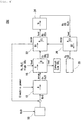
- FIG. 1 shows a schematic view of an electric power storage system according to the first embodiment of the present invention.
- an electric power storage system 10a includes a solid oxide electrolysis cell (SOEC) 12, a first CO 2 separator (CO 2 circulation unit) 14, a second CO 2 separator 16, an evaporator 18, a fuel production unit 20, and a control unit (not shown in the figure).
- SOEC solid oxide electrolysis cell
- CO 2 circulation unit CO 2 separator
- CO 2 separator 16 CO 2 circulation unit
- evaporator 18 evaporator 18
- fuel production unit 20 evaporator
- a gas flowing in a cathode channel of the SOEC 12 is abbreviated as "A”.
- a gas flowing in a feed channel of the first CO 2 separator 14 is abbreviated as “B 1 " and a gas flowing in a purge channel is abbreviated as “C 1 ".
- a gas flowing in a feed channel of the second CO 2 separator 16 is abbreviated as “B 2 " and a gas flowing in a purge channel is abbreviated as “C 2 ".
- suffixes "in” and “out” are added respectively like “A in " and "A out ".
- the SOEC 12 produces a synthesis gas from a raw material gas (A in ) containing CO 2 and H 2 O supplied to a cathode channel, and discharges an offgas (A out ) containing the synthesis gas.
- a in is supplied to the cathode channel while electric power is supplied between electrodes of the SOEC 12, reaction represented by the following expression (1) occurs at a cathode.
- the first CO 2 separator 14 separates CO 2 from A out , discharges an offgas (B 1out ) formed by removing all or some of CO 2 , and simultaneously returns a separation gas (C 1out ) containing CO 2 separated from A out to the cathode channel. That is, the first CO 2 separator 14 has the functions of:
- the structure of the first CO 2 separator 14 is not particularly limited as long as it exhibits such functions.
- the first CO 2 separator 14, as described on the upper right corner of Fig. 1 may be configured so as to arrange a feed channel and a purge channel adjacently with a separation membrane interposed in between (hereunder, also referred to as "separation membrane type".
- a separation membrane interposed in between hereunder, also referred to as "separation membrane type”.
- the first CO 2 separator 14, as described on the lower right corner of Fig. 1 may be configured so as to have two independent channels filled with a CO 2 adsorbent capable of absorbing and desorbing CO 2 reversibly (hereunder, also referred to as "batch switch type") .
- a CO 2 adsorbent capable of absorbing and desorbing CO 2 reversibly
- a gas containing CO 2 is fed to a feed channel
- CO 2 is absorbed by a CO 2 adsorbent.
- CO 2 is discharged from the CO 2 adsorbent.
- the feed channel and the purge channel are switched after a lapse of predetermined time, CO 2 can be absorbed and desorbed continuously.
- the first CO 2 separator 14 has a first feed channel and a first purge channel.
- An inlet of the first feed channel is connected to an outlet of the cathode channel of the SOEC 12 and an outlet of the first feed channel is connected to an inlet of the fuel production unit 20.
- an inlet of the first purge channel of the first CO 2 separator 14 is connected to an outlet of the evaporator 18 and an outlet of the first purge channel is connected to an inlet of a second purge channel of the second CO 2 separator 16.
- An offgas (A out ) discharged from the cathode channel of the SOEC 12 usually contains CO, H 2 , CO 2 , and H 2 O.
- a out is supplied to the first feed channel, CO 2 is separated and an offgas (B 1out ) containing CO and H 2 as main components is discharged from an outlet of the first feed channel. Further, a separation gas (C 1out ) containing CO 2 as the main component is discharged from an outlet of the first purge channel.
- the second CO 2 separator 16 separates CO 2 from a gas (B 2in ) supplied from a CO 2 source, and supplies a separation gas (C 2out ) containing CO 2 separated from B 2in to the cathode channel. That is, the second CO 2 separator has the function of supplying CO 2 that is the main raw material for producing a synthesis gas.
- the structure of the second CO 2 separator 16 is not particularly limited as long as it exhibits such functions.
- the second CO 2 separator 16 may be a separation membrane type or a batch switch type.
- the second CO 2 separator 16 has a second feed channel and a second purge channel.
- An inlet of the second feed channel is connected to an outside CO 2 source (for example, an automobile or a boiler) and an outlet of the second feed channel is open to the atmosphere.
- An inlet of the second purge channel of the second CO 2 separator 16 is connected to an outlet of the first purge channel of the first CO 2 separator 14 and an outlet of the second purge channel is connected to an inlet of the cathode channel of the SOEC 12.
- the evaporator 18, the first CO 2 separator 14, and the second CO 2 separator 16 are connected in series in this order in Fig. 1 , they may be connected in series in the order of the evaporator 18, the second CO 2 separator 16, and then the first CO 2 separator 14. Otherwise, an outlet of the evaporator 18 is branched into two outlets and the first CO 2 separator 14 and the second CO 2 separator 16 may be connected in parallel.
- the evaporator 18 adds H 2 O to a separation gas (C 1out ) coming from the first purge channel of the first CO 2 separator 14 and a separation gas (C 2out ) coming from the second purge channel of the second CO 2 separator 16 and produces a raw material gas (A in ). That is, the evaporator 18 is a supply source of H 2 O that is another main raw material for producing a synthesis gas.
- an outlet of the evaporator 18 is connected to an inlet of the first purge channel of the first CO 2 separator 14.
- the first CO 2 separator 14 and the second CO 2 separator 16 are connected in series.
- a mixed gas (C 2out ) of H 2 O and CO 2 is discharged from the second purge channel.
- the obtained mixed gas (C 2out ) is supplied as a raw material gas (A in ) to the cathode channel of the SOEC 12.
- the fuel production unit 20 produces a hydrocarbon (for example, methane) by using an offgas (B 1out ) discharged from the first feed channel of the first CO 2 separator 14 as a raw material.
- a hydrocarbon for example, methane
- B 1out offgas discharged from the first feed channel of the first CO 2 separator 14 as a raw material.
- the structure of the fuel production unit 20 is not particularly limited and a known unit can be used.
- the electric power storage system 10a has a control unit (not shown in the figure) to control the operation of the system.
- the control unit controls operating conditions (for example, temperatures, gas flow rates, and others) of the SOEC 12, the first CO 2 separator 14, the second CO 2 separator 16, the evaporator 18, and the fuel production unit 20.
- the electric power storage system 10a may further have a fuel utilization rate control unit to control a fuel utilization rate U f of the SOEC 12 to 25% or more to 55% or less during electrolysis.
- a fuel utilization rate U f is desirably 55% or less.
- the electric power storage system 10a has the first CO 2 separator 14 additionally having the function of recovering and reusing unreacted CO 2 .
- the first CO 2 separator 14 additionally having the function of recovering and reusing unreacted CO 2 .
- a fuel utilization rate U f in the SOEC 12 is excessively low, however, the production efficiency of a hydrocarbon deteriorates. Further, a circulation gas flow rate increases and pressure loss in a circulation gas route increases. A fuel utilization rate U f therefore is desirably 25% or more and more desirably 35% or more.
- Examples of methods of setting a fuel utilization rate U f low include:
- an H 2 O + CO 2 mixed gas (C 1out ) of a high concentration can be produced.
- resistance caused by concentration polarization reduces and a required electrolysis voltage can be reduced.
- a synthesis gas (CO + H 2 ) of a high concentration is produced from an H 2 O + CO 2 mixed gas and electric power by co-electrolysis. Furthermore, in the fuel production unit 20, a synthesis gas is converted to a hydrocarbon of a high concentration by catalytic reaction.
- CO 2 circulation unit since a CO 2 circulation unit is provided, CO 2 that has not been used in the SOEC 12 can be reused. As a result, the SOEC 12 can be set at a condition of a lower fuel utilization rate. Furthermore, by reusing CO 2 for electrolysis, thermal energy can be used effectively (thermal energy of an exhaust gas can be used effectively) . In addition, it is possible to inhibit concentration polarization caused by the increase of produced gas components (H 2 , CO) of co-electrolysis reaction from increasing and produce a synthesis gas with a lower electrolysis voltage.
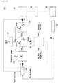
- Fig. 2 shows a schematic view of an electric power storage system according to the second embodiment of the present invention.
- the electric power storage system 10b includes a solid oxide electrolysis cell (SOEC) 12, a first CO 2 separator (CO 2 circulation unit) 14, a second CO 2 separator 16, an evaporator 18, a fuel production unit 20, an H 2 O separator (H 2 O circulation unit) 22, and a control unit (not shown in the figure).
- SOEC solid oxide electrolysis cell
- CO 2 circulation unit CO 2 separator
- second CO 2 separator 16 an evaporator 18
- fuel production unit 20
- H 2 O separator H 2 O circulation unit 22
- a control unit not shown in the figure.
- a gas flowing in a feed channel of the H 2 O separator 22 is abbreviated as "D” and a gas flowing in a purge channel is abbreviated as "E”.
- the H 2 O separator 22 is installed between the first CO 2 separator 14 and the fuel production unit 20. This point is different from the first embodiment.
- the H 2 O separator 22 may also be installed between the SOEC 12 and the first CO 2 separator 14 instead of the location shown in Fig. 2 . That is, H 2 O may be separated either after CO 2 is separated or before CO 2 is separated.
- the H 2 O separator 22 separates H 2 O from an offgas (B 1out ) coming from a first feed channel of the first CO 2 separator 14 (or an offgas (A out ) coming from a cathode channel of the SOEC 12), discharges an offgas (D out ) formed by removing all or some of H 2 O, and simultaneously returns a separation gas (E out ) containing separated H 2 O to the cathode channel.
- an offgas (B 1out ) coming from a first feed channel of the first CO 2 separator 14 (or an offgas (A out ) coming from a cathode channel of the SOEC 12) discharges an offgas (D out ) formed by removing all or some of H 2 O, and simultaneously returns a separation gas (E out ) containing separated H 2 O to the cathode channel.
- the structure of the H 2 O separator 22 is not particularly limited as long as it exhibits such functions.
- the H 2 O separator 22 may be of a separation membrane type (refer to upper right corner in Fig. 2 ) or a batch switch type (refer to lower right corner in Fig. 2 ).
- the H 2 O separator 22 has a third feed channel and a third purge channel.
- An inlet of the third feed channel is connected to an outlet of a first feed channel of the first CO 2 separator 14 and an outlet of the third feed channel is connected to an inlet of the fuel production unit 20. Further, an outlet of the third purge channel of the H 2 O separator 22 is connected to an outlet of the evaporator 18.
- an offgas (A out ) discharged from a cathode channel of the SOEC 12 firstly CO 2 is removed at the first CO 2 separator 14 and successively H 2 O is removed at the H 2 O separator 22.
- an offgas (D out ) containing CO + H 2 of a high concentration is discharged from an outlet of a third feed channel of the H 2 O separator 22. Further, since such D out is supplied to the fuel production unit 20, a fuel having a higher fuel component concentration can be produced.
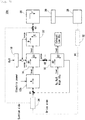
- Fig. 3 shows a schematic view of an electric power storage system according to the third embodiment of the present invention.
- the electric power storage system 10c includes a solid oxide electrolysis cell (SOEC) 12, a CO 2 separator 16, an evaporator 18, a reverse water-gas shift reactor (RWGSR) 24, a fuel production unit 20, and a control unit (not shown in the figure).
- SOEC solid oxide electrolysis cell
- CO 2 separator CO 2 separator
- RWGSR reverse water-gas shift reactor
- G a gas flowing in the RWGSR 24
- the SOEC 12 produces H 2 from a raw material gas (A in ) containing H 2 O supplied to a cathode channel, and discharges an offgas (A out ) containing H 2 .
- a in is supplied to the cathode channel while electric power is applied between electrodes of the SOEC 12, reaction represented by the following expression (2) occurs at a cathode.
- the CO 2 separator 16 separates CO 2 from a gas (B in ) supplied from a CO 2 source, adds separated CO 2 to A out , and discharges an offgas (C out ) containing H 2 and CO 2 . That is, the CO 2 separator 16 is a supply source of CO 2 that is a main raw material for producing a synthesis gas.
- the structure of the CO 2 separator 16 is not particularly limited as long as it exhibits such functions.
- the CO 2 separator 16 has a feed channel and a purge channel.
- An inlet of the feed channel is connected to an outside CO 2 source (for example, an automobile or a boiler) and an outlet of the feed channel is open to the atmosphere.
- An inlet of the purge channel is connected to an outlet of the cathode channel of the SOEC 12 and an outlet of the purge channel is connected to an inlet of the RWGSR 24.
- the evaporator 18 generates a raw material gas (A in ) containing H 2 O and supplies it to the cathode channel of the SOEC 12.
- An outlet of the evaporator 18 is connected to an inlet of the cathode channel of the SOEC 12.
- the structure of the evaporator 18 is not particularly limited as long as it exhibits such functions.
- the reverse water-gas shift reactor (RWGSR) 24 carries out reverse water-gas shift reaction by using an offgas (C out ) coming from the CO 2 separator 16, and discharges an offgas (G out ) containing a synthesis gas.
- the reverse water-gas shift reaction is represented by the following expression (3). CO 2 + H 2 ⁇ H 2 O + CO (3)
- an inlet of the RWGSR 24 is connected to an outlet of a purge channel of the CO 2 separator 16 and an outlet of the RWGSR 24 is connected to an inlet of the fuel production unit 20.
- the structure of the RWGSR 24 is not particularly limited and a known unit can be used.
- the fuel production unit 20 produces a hydrocarbon (for example, methane) by using an offgas (G out ) discharged from the RWGSR 24 as a raw material.
- a hydrocarbon for example, methane
- G out offgas discharged from the RWGSR 24
- the structure of the fuel production unit 20 is not particularly limited and a known unit can be used.
- the electric power storage system 10c has a control unit (not shown in the figure) to control the operation of the system.
- the control unit controls operating conditions (for example, temperatures, gas flow rates, and others) of the SOEC 12, the CO 2 separator 16, the evaporator 18, the RWGSR 24, and the fuel production unit 20.
- the electric power storage system 10c may further have a fuel utilization rate control unit to control a fuel utilization rate U f of the SOEC 12 to 25% or more to 55% or less during electrolysis.
- a fuel utilization rate control unit to control a fuel utilization rate U f of the SOEC 12 to 25% or more to 55% or less during electrolysis.
- the details of the fuel utilization rate control unit are similar to the first embodiment and hence the explanations are omitted.
- the SOEC 12 produces a gas (A out ) containing H 2 by using H 2 O generated in the evaporator 18 as a raw material through steam electrolysis.
- a out is supplied to a purge channel of the CO 2 separator 16 and mixed with CO 2 supplied from a feed channel.
- a mixed gas (C out ) containing H 2 and CO 2 is discharged from the purge channel of the CO 2 separator 16.
- C out is supplied further to the RWGSR 24 and some of H 2 contained in C out is consumed there by reverse water-gas shift reaction. As a result, a synthesis gas (CO + H 2 ) containing H 2 O is produced. A produced mixed gas (G out ) is sent from the RWGSR 24 to the fuel production unit 20 and consumed for synthesizing a hydrocarbon.
- Fig. 4 shows a schematic view of an electric power storage system according to the fourth embodiment of the present invention.
- the electric power storage system 10d includes a solid oxide electrolysis cell (SOEC) 12, a CO 2 separator 16, an evaporator 18, a reverse water-gas shift reactor (RWGSR) 24, a first H 2 O separator (H 2 O circulation unit) 22, a second H 2 O separator (H 2 O circulation unit) 26, a fuel production unit 20, and a control unit (not shown in the figure).
- SOEC solid oxide electrolysis cell
- CO 2 separator 16 CO 2 separator
- RWGSR reverse water-gas shift reactor
- the first H 2 O separator 22 is installed between the CO 2 separator 16 and the RWGSR 24. Further, the second H 2 O separator 26 is installed between the RWGSR 24 and the fuel production unit 20. This point is different from the third embodiment.
- first H 2 O separator 22 and the second H 2 O separator 26 are installed in the example shown in Fig. 4 , it is also possible to install either of them. Further, the first H 2 O separator 22 may be installed between the SOEC 12 and the CO 2 separator 16.
- the first H 2 O separator 22 separates H 2 O from an offgas (C out ) coming from the CO 2 separator 16 (or an offgas (A out ) coming from the SOEC 12), discharges an offgas (D 1out ) formed by removing all or some of H 2 O, and simultaneously returns a separation gas (E 1out ) containing separated H 2 O to the cathode channel.
- the second H 2 O separator 26 separates H 2 O from an offgas (G out ) coming from the RWGSR 24, discharges an offgas (D 2out ) formed by removing all or some of H 2 O, and simultaneously returns a separation gas (E 2out ) containing separated H 2 O to the cathode channel.
- an inlet of a third feed channel of the first H 2 O separator 22 is connected to an outlet of a purge channel of the CO 2 separator 16 and an outlet of the third feed channel is connected to an inlet of the RWGSR 24. Further, an outlet of a third purge channel of the first H 2 O separator 22 is connected to an outlet of the evaporator 18.
- An inlet of a fourth feed channel of the second H 2 O separator 26 is connected to an outlet of the RWGSR 24 and an outlet of the fourth feed channel is connected to an inlet of the fuel production unit 20. Further, an outlet of a fourth purge channel of the second H 2 O separator 26 is connected to an inlet of the third purge channel of the first H 2 O separator 22.
- H 2 O can be removed from an offgas (G out ) of the RWGSR 24.
- G out an offgas of the RWGSR 24.
- both purge channels of the first H 2 O separator 22 and the second H 2 O separator 26 are connected to an outlet of the evaporator 18.
- high temperature steam contained in E 1out and E 2out can be reused.
- thermal energy required for additionally generating steam in the evaporator 18 is reduced and a fuel can be produced with a higher degree of efficiency.
- An electric power storage and supply system includes:
- Fig. 5 shows a schematic view of an electric power storage and supply system according to the present invention.
- the electric power storage and supply system 10e includes a reversible SOC (R-SOC) 12b, a first CO 2 separator 14, a second CO 2 separator 16, an evaporator 18, a fuel production unit 20, an H 2 O separator 22, a control unit (not shown in the figure), a storage tank 28, a first pressure regulator 30, a second pressure regulator 32, and an ejector 34. That is, the electric power storage and supply system 10e shown in Fig. 5 is configured by adding the storage tank 28, the first pressure regulator 30, the second pressure regulator 32, and the ejector 34 to the electric power storage system 10b shown in Fig. 2 .
- R-SOC reversible SOC
- R-SOC 12b can switch between:
- the first CO 2 separator 14 is used for increasing the purity of a synthesis gas supplied to the fuel production unit 20 and constitutes a part of a "hydrocarbon production unit" during an SOEC mode. Further, it constitutes a part of a "raw material circulation unit” to recover CO 2 from A out .
- the first CO 2 separator 14 constitutes a part of a "fuel circulation unit" to recover an unreacted fuel from A' out by separating CO 2 from A' out during an SOFC mode.
- the separated CO 2 is discarded directly to the external environment during the SOFC mode.
- a three-way valve V3 to discharge CO 2 to the external environment is installed in a pipe connecting a first purge channel of the first CO 2 separator 14 and a second purge channel of the second CO 2 separator 16.
- the second CO 2 separator 16 is used for supplying CO 2 that is a main raw material and constitutes a part of a "hydrocarbon production unit" during an SOEC mode. Further, the second CO 2 separator 16 does not have the function of recovering CO 2 by itself but is connected in series to a first purge channel of the first CO 2 separator 14, and hence constitutes a part of a "raw material circulation unit” too.
- the second CO 2 separator 16 is not used during an SOFC mode.
- a three-way valve V1 to temporarily disconnect the second CO 2 separator 16 from a system is installed between the second CO 2 separator 16 and an anode channel of an R-SOC 12b (during an SOFC mode).
- the evaporator 18 adds H 2 O to a separation gas (C 1out ) coming from a first purge channel of the first CO 2 separator 14 and a separation gas (C 2out ) coming from a second purge channel of the second CO 2 separator 16 and produces a raw material gas (A in ) during an SOEC mode.
- the evaporator 18 is not used during an SOFC mode.
- the H 2 O separator 22 is used for increasing the purity of a synthesis gas supplied to the fuel production unit 20 and constitutes a part of a "hydrocarbon production unit" during an SOEC mode. Further, the H 2 O separator 22 constitutes a part of a "raw material circulation unit” to recover H 2 O from A out .
- the H 2 O separator 22 constitutes a part of a "fuel circulation unit" to recover an unreacted fuel from A' out by separating H 2 O from A' out during an SOFC mode.
- a recovered fuel is returned to the R-SOC 12b.
- a three-way valve V2 is installed between the H 2 O separator 22 and the fuel production unit 20. Further, a remaining outlet of the three-way valve V2 is connected to the suction side of the ejector 34.
- the fuel production unit 20 constitutes a part of a "hydrocarbon production unit" during an SOEC mode. A produced hydrocarbon is stored in the storage tank 28. Other points related to the fuel production unit 20 are similar to the second embodiment and hence explanations are omitted.
- the first pressure regulator 30 is installed between an outlet of the fuel production unit 20 and an inlet of the storage tank 28.
- An outlet of the storage tank 28 is connected to a drive side of the ejector 34.
- an on-off valve V4 and the second pressure regulator 32 are installed between the ejector 34 and the storage tank 28.
- an outlet of the ejector 34 is connected to a cathode channel of the R-SOC 12b (during an SOEC mode) through the three-way valve V1.
- the first pressure regulator 30 and the second pressure regulator 32 increase and decrease the pressure of a hydrocarbon when the hydrocarbon is stored and discharged.
- an expander pressure reducing device
- a compressor boost
- a high pressure gas produced in a system during an SOEC mode can be stored at a low pressure.
- a hydrocarbon can be used in the state of being pressurized to a predetermined pressure during an SOFC mode.
- the ejector 34 supplies a hydrocarbon stored in the storage tank 28 to an anode of the R-SOC 12b (during an SOFC mode) . Further, the ejector 34 is used also for supplying an unreacted fuel recovered from A' out to the R-SOC 12b.
- An outlet of the storage tank 28 is connected to a drive side of the ejector 34 and an outlet of a feed channel of the H 2 O separator 22 is connected to a suction side of the ejector 34. In this state, when a hydrocarbon supplied from the storage tank 28 is ejected from a nozzle on the drive side at high pressure, an offgas (D out ) in the H 2 O separator 22 is sucked by negative pressure around the nozzle.
- the electric power storage and supply system 10e has a control unit (not shown in the figure) to control the operation of the system.
- the control unit controls the operating conditions (for example, temperatures, gas flow rates, and others) of the R-SOC 12b, the first CO 2 separator 14, the second CO 2 separator 16, the evaporator 18, the fuel production unit 20, the first pressure regulator 30, the second pressure regulator 32, and valves V1 to V4.
- the electric power storage and supply system 10e may further have a fuel utilization rate control unit to control a fuel utilization rate of the R-SOC to 25% or more to 55% or less during electrolysis reaction and/or electric power generation reaction.
- the details of the fuel utilization rate control unit are similar to the second embodiment and hence the explanations are omitted.
- Fig. 6 shows a schematic view showing the flow of a gas in an SOFC mode of the electric power storage and supply system 10e.
- the ejector 34 and an inlet of an anode channel of the R-SOC 12b (during an SOFC mode) are connected through the three-way valve V1.
- An outlet of a feed channel of the H 2 O separator 22 and a suction side of the ejector 34 are connected through the three-way valve V2.
- An outlet of a purge channel of the first CO 2 separator 14 and an exhaust side are connected through the three-way valve V3.
- An offgas (A' out ) of the R-SOC 12b is sent to the first CO 2 separator 14 and an H 2 O separator 22, and CO 2 and H 2 O are removed respectively.
- H 2 O separated at the H 2 O separator 22 is sent to a purge channel of the first CO 2 separator 14 and used for purging CO 2 .
- the purged CO 2 is discharged together with H 2 O to the external environment through V3.
- an unreacted fuel is contained in an offgas (D out ) formed after CO 2 and H 2 O are removed.
- the unreacted fuel is sucked from a suction side of the ejector 34 through the three-way valve V2.
- Fig. 7 shows a schematic view showing the flow of a gas in an SOEC mode of the electric power storage and supply system.
- An outlet of a second purge channel of the second CO 2 separator 16 and an inlet of a cathode channel of the R-SOC 12b (during an SOEC mode) are connected through the three-way valve V1.
- An outlet of a feed channel of the H 2 O separator 22 and an inlet of the fuel production unit 20 are connected through the three-way valve V2.
- An outlet of a first purge channel of the first CO 2 separator 14 and an inlet of the second purge channel of the second CO 2 separator 16 are connected through the three-way valve V3. Further, the valve V4 is closed.
- electric power can be stored in the form of a hydrocarbon.
- Ni-YSZ, LaSrMnO 3 , and YSZ are selected as the materials of an anode, a cathode, and an electrolyte membrane in an SOFC, respectively. Further, the values described in Table 1 are used as the thickness and the resistivity of each of the materials.
- a generated voltage V and a generated electric power W in an SOFC are obtained through the following expressions (1) and (2), respectively. Further, an electrolysis voltage V and a required electric power W in an SOEC are obtained through the following expressions (3) and (4), respectively.
- Generated voltage V V th ⁇ V act ⁇ V ohm
- Generated electric power W V ⁇ J e
- V th represents the increase of a required electrolysis voltage caused by concentration polarization (Nernst equation) .
- V act represents the increase of a required electrolysis voltage caused by activation polarization.
- V ohm represents the increase of a required electrolysis voltage caused by resistance polarization (Reference Literature 1).
- V th , V act , and V ohm are represented by the following expressions (5) to (7) respectively.
- J e in the expressions (2) and (4) represents a current density.
- V th E 0 T ⁇ RT 4 F ln P an , H 20 ⁇ P an , C 02 P an , H 2 ⁇ P an , C 0 ⁇ P ca , 02 ⁇ : S 0 FC mode , + : S 0 EC mode
- E 0 T ⁇ 1 4 F ⁇ G H 2 T + ⁇ G C 0 T
- V act V a ⁇ ln J c / J 0 LN 1 + J c / J 0 ⁇ ln 1 + J e / J 0
- V ohm J e ⁇ ⁇ an ⁇ ⁇ an ⁇ ⁇ ca
- thermoneutral condition In SOEC electrolysis, as an operating temperature lowers, a required electrolysis voltage tends to increase and an electric power generation efficiency tends to lower. Likewise, at a certain operating temperature, as a current density increases, a required electrolysis voltage tends to increase and an electric power generation efficiency tends to lower. Further, under a certain operating condition, there exists a condition where a calorific loss is nearly equal to heat absorption (T ⁇ S) (thermoneutral condition). When a system is operated under a thermoneutral condition, the system can be downsized, highly efficient, and more durable. Various studies are hereunder carried out mainly under a thermoneutral condition (operating temperature: 750°C, current density: 0.8 A/cm 2 ).
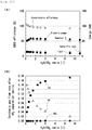
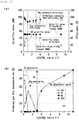
- Fig. 8A shows a relationship between a fuel utilization rate and an SOEC efficiency or an energy. Further, Fig. 8B shows a relationship between a fuel utilization rate and a required electrolysis voltage. Following findings are obtained from Figs. 8A and 8B .
- An offgas (A out ) discharged from the SOEC 12 contains a synthesis gas (CO + H 2 ) as the main component but also contains unreacted CO 2 and H 2 O.
- a out is supplied to the first CO 2 separator 14
- CO 2 can be separated from A out .
- the proportion of CO 2 separated from A out (CO 2 separation rate) can be controlled arbitrarily.
- CH 4 concentrations in gases produced when synthesis gases having different CO 2 separation rates are supplied to the fuel production unit 20 are studied.
- Fig. 9A shows a relationship between a CO 2 separation rate and a synthesis gas flow rate.
- Fig. 9B shows a relationship between a CO 2 separation rate and a produced gas concentration. Following findings are obtained from Figs. 9A and 9B .
- Fig. 10A shows a relationship between an H 2 O/CO 2 ratio and an SOEC efficiency or an energy.
- Fig. 10B shows a relationship between an H 2 O/CO 2 ratio and a synthesis gas flow rate after CO 2 separation. Following findings are obtained from Figs. 10A and 10B .
- Fig. 11A shows a relationship between an H 2 O/CO 2 ratio and a calorific value or an efficiency.
- Fig. 11B shows a relationship between an H 2 O/CO 2 ratio and a produced gas dry concentration.
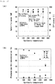
- Fig. 12A shows a relationship between a synthesis temperature of CH 4 and a calorific value or an efficiency.
- Fig. 12B shows a relationship between a synthesis temperature of CH 4 and a produced gas dry concentration.
- the system efficiencies of the electric power storage systems 10c and 10d shown in Fig. 3 and Fig. 4 are obtained by simulation.
- the simulation method is the same as Example 1.
- Fig. 13A shows a relationship between an H 2 O/CO 2 ratio and a calorific value or an efficiency.
- Fig. 13B shows a relationship between an H 2 O/CO 2 ratio and a produced gas dry concentration.
- the system efficiency of the electric power storage and supply system 10e shown in Fig. 5 is obtained by simulation.
- the simulation method is the same as Example 1.
- Fig. 14A shows electric power generation efficiencies and cell voltages in an SOFC mode (750°C, 0.4 A/cm 2 ).
- Fig. 14B shows fuel production efficiencies and CH 4 concentrations in an SOEC mode (750°C, 0.8 A/cm 2 ).
- Table 2 shows detailed operating conditions of "Conventional”, “AGR (Anode offGas Recirculation)", “Gas separation”, and “Low U f operation” in Fig. 14A .
- Table 3 shows detailed operating conditions of "Conventional”, “CGR (Cathode offGas Recirculation)” and “Low U f operation” in Fig. 14B .
- An electric power storage system and an electric power storage and supply system according to the present invention can be used for a system of storing and using surplus electric power in renewable energy (sun light, wind power, and others), a dispersion type electric power source, and the like.
Landscapes
- Chemical & Material Sciences (AREA)
- Engineering & Computer Science (AREA)
- Chemical Kinetics & Catalysis (AREA)
- Electrochemistry (AREA)
- Organic Chemistry (AREA)
- Life Sciences & Earth Sciences (AREA)
- Sustainable Development (AREA)
- Metallurgy (AREA)
- Materials Engineering (AREA)
- Manufacturing & Machinery (AREA)
- Sustainable Energy (AREA)
- General Chemical & Material Sciences (AREA)
- Inorganic Chemistry (AREA)
- Fuel Cell (AREA)
- Electrolytic Production Of Non-Metals, Compounds, Apparatuses Therefor (AREA)
Abstract
Description
- The present invention relates to an electric power storage system and an electric power storage and supply system, more specifically to an electric power storage system of producing a synthesis gas from CO2 and H2O with a solid oxide electrolysis cell, and synthesizing a hydrocarbon fuel from the synthesis gas and an electric power storage and supply system capable of synthesizing a hydrocarbon fuel and generating electricity by using the hydrocarbon fuel reversibly.
- A solid oxide fuel cell (SOFC) is a fuel cell using an oxide ion conductor as an electrolyte. When a fuel gas such as H2, CO, or CH4 is supplied to an anode and O2 is supplied to a cathode in an SOFC, electrode reaction proceeds and electric power can be taken out. CO2 and H2O produced by the electrode reaction are discharged outside the SOFC.
- In contrast, a solid oxide electrolysis cell (SOEC) has the same structure as an SOFC but causes a reaction opposite to an SOFC. That is, by supplying CO2 and H2O to an SOEC and applying electric current between electrodes, CO and H2 can be produced.
- By using an SOEC, a synthesis gas (CO + H2) can be produced from CO2 and H2O. Further, by using an obtained synthesis gas, a hydrocarbon such as methane can be produced. That is, by using an SOEC, electric energy can be stored as chemical energy. Consequently, various electric power storage systems using an SOEC have heretofore been proposed.
- For example,
Patent Literature 1 discloses a method of: - (a) converting direct sunlight into thermal energy,
- (b) heating a synthesis gas producing cell to 500°C to 1,000°C by using the thermal energy and producing a synthesis gas from CO2 and H2O, and
- (c) feeding the flow of the synthesis gas obtained in the synthesis gas producing cell to a catalytic reactor and producing a hydrocarbon fuel.
- When an SOEC is used, a synthesis gas (CO, H2) can be produced by using CO2 and H2O as a fuel. At this time, when a fuel utilization rate Uf increases, the amount of a gas (CO, H2) produced by electrolytic reaction increases and concentration polarization is caused. As a result, Nernst loss increases, hence a required electrolysis voltage increases, and an electrolysis efficiency lowers.
- On the other hand, when a fuel utilization rate Uf decreases, an electrolysis voltage can be inhibited from increasing but the concentration of CO2 and H2O in a synthesis gas increases. As a result, the reaction rate of hydrocarbon synthesis reaction lowers and the concentration of a hydrocarbon fuel contained in a gas after the synthesis reaction also lowers. Further, unreacted CO2 and H2O are discharged out of a system while holding thermal energy and hence a thermal efficiency is low. In order to improve a thermal efficiency, it is necessary to use captured CO2 and H2O effectively and reduce thermal energy required for heating a supply gas.
- [Patent Literature 1] Japanese Unexamined Patent Application Publication (Translation of PCT Application) No.
2016-511296 - A problem to be solved by the present invention is to provide an electric power storage system capable of synthesizing a hydrocarbon at a high electrolysis efficiency, and inhibiting the reaction rate of hydrocarbon synthesis reaction and the concentration of a hydrocarbon contained in a gas after the synthesis reaction from lowering.
- Further, another problem to be solved by the present invention is to provide an electric power storage and supply system capable of synthesizing a hydrocarbon highly efficiently and generating electricity highly efficiently by using the synthesized hydrocarbon reversibly.
- In order to solve the above problems, a first electric power storage system according to the present invention includes:
- a solid oxide electrolysis cell (SOEC) to produce a synthesis gas from a raw material gas (Ain) containing CO2 and H2O supplied to a cathode channel, and discharge an offgas (Aout) containing the synthesis gas;
- a first CO2 separator to separate CO2 from the Aout, discharge an offgas (B1out) formed by removing all or some of CO2, and simultaneously return a separation gas (C1out) containing CO2 separated from the Aout to the cathode channel;
- a second CO2 separator to separate CO2 from a gas (B2in) supplied from a CO2 source and supply a separation gas (C2out) containing CO2 separated from the B2in to the cathode channel;
- an evaporator to add H2O to the C1out and the C2out and produce the Ain; and
- a fuel production unit to synthesize a hydrocarbon by using the B1out.
- A second electric power storage system according to the present invention includes:
- a solid oxide electrolysis cell (SOEC) to produce H2 from a raw material gas (Ain) containing H2O supplied to a cathode channel, and discharge an offgas (Aout) containing H2;
- a CO2 separator to separate CO2 from a gas (Bin) supplied from a CO2 source, add separated CO2 to the Aout, and discharge an offgas (Cout) containing H2 and CO2;
- an evaporator to supply the Ain to the cathode channel;
- a reverse water-gas shift reactor (RWGSR) to carry out reverse water-gas shift reaction by using the Cout, and discharge an offgas (Gout) containing a synthesis gas; and
- a fuel production unit to synthesize a hydrocarbon by using the Gout.
- An electric power storage and supply system according to the present invention includes:
- a reversible SOC (R-SOC) capable of switching between an SOEC mode of co-electrolyzing CO2 and H2O and an SOFC mode of generating electricity by using a hydrocarbon as a fuel;
- a hydrocarbon production unit to produce a synthesis gas from CO2 and H2O, further synthesize the hydrocarbon from the synthesis gas, and store the obtained hydrocarbon when the R-SOC is in the SOEC mode;
- an electric power generation unit to supply the stored hydrocarbon to the R-SOC and generate electricity when the R-SOC is in the SOFC mode;
- a raw material circulation unit to recover unreacted CO2 and H2O contained in the synthesis gas and return the unreacted CO2 and H2O to the R-SOC when the R-SOC is in the SOEC mode; and
- a fuel circulation unit to recover an unreacted fuel contained in an offgas of the R-SOC and return the unreacted fuel to the R-SOC when the R-SOC is in the SOFC mode.
- When electrolysis is carried out with an SOEC, by recovering an unreacted raw material (CO2, H2O) from an offgas (Aout) of the SOEC and adding the unreacted raw material to a raw material gas (Ain), a yield in hydrocarbon synthesis reaction and a hydrocarbon concentration can be inhibited from lowering. At the same time, by lowering a fuel utilization rate of the SOEC, an electrolysis voltage can be inhibited from increasing and an electrolysis efficiency also improves.
- The same applies to the case of operating an R-SOC in an SOFC mode and, by recovering an unreacted fuel contained in an offgas (A'out), adding it to a fuel gas (A'in), and simultaneously generating electricity at a low fuel utilization rate, a substantial fuel utilization rate can improve without lowering an electric power generation efficiency.
-
-
Fig. 1 is a schematic view of an electric power storage system according to a first embodiment of the present invention; -
Fig. 2 is a schematic view of an electric power storage system according to a second embodiment of the present invention; -
Fig. 3 is a schematic view of an electric power storage system according to a third embodiment of the present invention; -
Fig. 4 is a schematic view of an electric power storage system according to a fourth embodiment of the present invention; -
Fig. 5 is a schematic view of an electric power storage and supply system according to the present invention; -
Fig. 6 is a schematic view showing the flow of a gas in an SOFC mode in a system shown inFig. 5 ; -
Fig. 7 is a schematic view showing the flow of a gas in an SOEC mode in a system shown inFig. 5 ; -
Fig. 8A is a graph showing a relationship between a fuel utilization rate and an SOEC efficiency or an energy; -
Fig. 8B is a graph showing a relationship between a fuel utilization rate and a required electrolysis voltage; -
Fig. 9A is a graph showing a relationship between a CO2 separation rate and a synthesis gas flow rate; -
Fig. 9B is a graph showing a relationship between a CO2 separation rate and a produced gas concentration; -
Fig. 10A is a graph showing a relationship between an H2O/CO2 ratio and an SOEC efficiency or an energy; -
Fig. 10B is a graph showing a relationship between an H2O/CO2 ratio and a synthesis gas flow rate after CO2 separation; -
Fig. 11A is a graph showing a relationship between an H2O/CO2 ratio and a calorific value or an efficiency; -
Fig. 11B is a graph showing a relationship between an H2O/CO2 ratio and a produced gas dry concentration; -
Fig. 12A is a graph showing a relationship between a synthesis temperature of CH4 and a calorific value or an efficiency; -
Fig. 12B is a graph showing a relationship between a synthesis temperature of CH4 and a produced gas dry concentration; -
Fig. 13A is a graph showing a relationship between an H2O/CO2 ratio and a calorific value or an efficiency; -
Fig. 13B is a graph showing a relationship between an H2O/CO2 ratio and a produced gas dry concentration; -
Fig. 14A is a graph showing electric power generation efficiencies and cell voltages in an SOFC mode (750°C, 0.4 A/cm2) ; and -
Fig. 14B is a graph showing fuel production efficiencies and CH4 concentrations in an SOEC mode (750°C, 0.8 A/cm2). - An embodiment according to the present invention is hereunder explained in detail.
-
Fig. 1 shows a schematic view of an electric power storage system according to the first embodiment of the present invention. InFig. 1 , an electricpower storage system 10a includes a solid oxide electrolysis cell (SOEC) 12, a first CO2 separator (CO2 circulation unit) 14, a second CO2 separator 16, anevaporator 18, afuel production unit 20, and a control unit (not shown in the figure). - Here, in the following explanations, for convenience sake, a gas flowing in a cathode channel of the
SOEC 12 is abbreviated as "A". Likewise, a gas flowing in a feed channel of the first CO2 separator 14 is abbreviated as "B1" and a gas flowing in a purge channel is abbreviated as "C1". Further, a gas flowing in a feed channel of the second CO2 separator 16 is abbreviated as "B2" and a gas flowing in a purge channel is abbreviated as "C2". Furthermore, when an inlet gas and an outlet gas are to be distinguished from each other, suffixes "in" and "out" are added respectively like "Ain" and "Aout". - The
SOEC 12 produces a synthesis gas from a raw material gas (Ain) containing CO2 and H2O supplied to a cathode channel, and discharges an offgas (Aout) containing the synthesis gas. When Ain is supplied to the cathode channel while electric power is supplied between electrodes of theSOEC 12, reaction represented by the following expression (1) occurs at a cathode.
CO2 + H2O +4e- → CO + H2 + 2O2- (1)
- In reality, however, since not all of the raw material contained in Ain is consumed in the reaction, not only CO and H2 but also unreacted CO2 and H2O are contained in Aout. When a fuel utilization rate Uf is set low in particular, relatively large amount of CO2 and H2O remain.
- The first CO2 separator 14 separates CO2 from Aout, discharges an offgas (B1out) formed by removing all or some of CO2, and simultaneously returns a separation gas (C1out) containing CO2 separated from Aout to the cathode channel. That is, the first CO2 separator 14 has the functions of:
- (a) supplying a synthesis gas of a high concentration to the
fuel production unit 20; and - (b) recovering unreacted CO2 contained in Aout and reusing it for electrolysis.
- The structure of the first CO2 separator 14 is not particularly limited as long as it exhibits such functions.
- The first CO2 separator 14, as described on the upper right corner of
Fig. 1 , may be configured so as to arrange a feed channel and a purge channel adjacently with a separation membrane interposed in between (hereunder, also referred to as "separation membrane type". When a gas containing CO2 is supplied to the feed channel, only CO2 is discharged to the purge channel through the separation membrane. - Otherwise, the first CO2 separator 14, as described on the lower right corner of
Fig. 1 , may be configured so as to have two independent channels filled with a CO2 adsorbent capable of absorbing and desorbing CO2 reversibly (hereunder, also referred to as "batch switch type") . When a gas containing CO2 is fed to a feed channel, CO2 is absorbed by a CO2 adsorbent. On the other hand, when a purge gas is fed to a purge channel, CO2 is discharged from the CO2 adsorbent. When the feed channel and the purge channel are switched after a lapse of predetermined time, CO2 can be absorbed and desorbed continuously. - In the example shown in
Fig. 1 , the first CO2 separator 14 has a first feed channel and a first purge channel. An inlet of the first feed channel is connected to an outlet of the cathode channel of theSOEC 12 and an outlet of the first feed channel is connected to an inlet of thefuel production unit 20. Further, an inlet of the first purge channel of the first CO2 separator 14 is connected to an outlet of theevaporator 18 and an outlet of the first purge channel is connected to an inlet of a second purge channel of the second CO2 separator 16. - An offgas (Aout) discharged from the cathode channel of the
SOEC 12 usually contains CO, H2, CO2, and H2O. When Aout is supplied to the first feed channel, CO2 is separated and an offgas (B1out) containing CO and H2 as main components is discharged from an outlet of the first feed channel. Further, a separation gas (C1out) containing CO2 as the main component is discharged from an outlet of the first purge channel. - The second CO2 separator 16 separates CO2 from a gas (B2in) supplied from a CO2 source, and supplies a separation gas (C2out) containing CO2 separated from B2in to the cathode channel. That is, the second CO2 separator has the function of supplying CO2 that is the main raw material for producing a synthesis gas.
- The structure of the second CO2 separator 16 is not particularly limited as long as it exhibits such functions. For example, the second CO2 separator 16 may be a separation membrane type or a batch switch type.
- In the example shown in
Fig. 1 , the second CO2 separator 16 has a second feed channel and a second purge channel. An inlet of the second feed channel is connected to an outside CO2 source (for example, an automobile or a boiler) and an outlet of the second feed channel is open to the atmosphere. An inlet of the second purge channel of the second CO2 separator 16 is connected to an outlet of the first purge channel of the first CO2 separator 14 and an outlet of the second purge channel is connected to an inlet of the cathode channel of theSOEC 12. - Here, although the
evaporator 18, the first CO2 separator 14, and the second CO2 separator 16 are connected in series in this order inFig. 1 , they may be connected in series in the order of theevaporator 18, the second CO2 separator 16, and then the first CO2 separator 14. Otherwise, an outlet of theevaporator 18 is branched into two outlets and the first CO2 separator 14 and the second CO2 separator 16 may be connected in parallel. - The
evaporator 18 adds H2O to a separation gas (C1out) coming from the first purge channel of the first CO2 separator 14 and a separation gas (C2out) coming from the second purge channel of the second CO2 separator 16 and produces a raw material gas (Ain). That is, theevaporator 18 is a supply source of H2O that is another main raw material for producing a synthesis gas. - In the example shown in
Fig. 1 , an outlet of theevaporator 18 is connected to an inlet of the first purge channel of the first CO2 separator 14. The first CO2 separator 14 and the second CO2 separator 16 are connected in series. As a result, when H2O generated at theevaporator 18 is supplied to the first CO2 separator 14 and the second CO2 separator 16, a mixed gas (C2out) of H2O and CO2 is discharged from the second purge channel. The obtained mixed gas (C2out) is supplied as a raw material gas (Ain) to the cathode channel of theSOEC 12. - The
fuel production unit 20 produces a hydrocarbon (for example, methane) by using an offgas (B1out) discharged from the first feed channel of the first CO2 separator 14 as a raw material. The structure of thefuel production unit 20 is not particularly limited and a known unit can be used. - The electric
power storage system 10a has a control unit (not shown in the figure) to control the operation of the system. In the example shown inFig. 1 , the control unit controls operating conditions (for example, temperatures, gas flow rates, and others) of theSOEC 12, the first CO2 separator 14, the second CO2 separator 16, theevaporator 18, and thefuel production unit 20. - The electric
power storage system 10a may further have a fuel utilization rate control unit to control a fuel utilization rate Uf of theSOEC 12 to 25% or more to 55% or less during electrolysis. In general, when a fuel utilization rate of theSOEC 12 lowers, an electrolysis voltage lowers and an electrolysis efficiency improves. For the purpose, a fuel utilization rate Uf is desirably 55% or less. When a fuel utilization rate Uf lowers, however, unreacted raw materials and thermal energy discarded outside a system increase and the production efficiency of a hydrocarbon produced in thefuel production unit 20 also lowers. - In contrast, the electric
power storage system 10a according to the present embodiment has the first CO2 separator 14 additionally having the function of recovering and reusing unreacted CO2. As a result, even when a fuel utilization rate Uf in theSOEC 12 is set low, unreacted raw materials discarded outside a system can be reduced. That is, a substantial fuel utilization rate can improve without increasing an electrolysis voltage. - When a fuel utilization rate Uf in the
SOEC 12 is excessively low, however, the production efficiency of a hydrocarbon deteriorates. Further, a circulation gas flow rate increases and pressure loss in a circulation gas route increases. A fuel utilization rate Uf therefore is desirably 25% or more and more desirably 35% or more. - Examples of methods of setting a fuel utilization rate Uf low include:
- (a) a method of reducing the length of the cathode channel in the
SOEC 12 so as to be able to obtain an intended Uf under a specific operating condition; and - (b) a method of controlling the flow rate and concentration of a gas flowing in each of units, an operating temperature in each of the units, and others by using the control unit so as to be able to obtain an intended Uf.
- When a mixed gas (B2in) containing a large amount of CO2 such as an exhaust gas is fed to the second feed channel of the second CO2 separator 16, CO2 in B2in is discharged to the second purge channel and the remaining gas is discharged as an offgas (B2out) containing CO2 of a low concentration from the second feed channel to the atmosphere.
- At the same time, when the
evaporator 18 is operated and steam is supplied to the second purge channel of the second CO2 separator 16, a mixed gas (H2O + CO2) necessary for SOEC co-electrolysis is produced. An obtained mixed gas (C2out) is supplied as a raw material gas (Ain) to the cathode channel of theSOEC 12. - When Ain is supplied to the cathode channel, CO and H2 are produced by electrolysis reaction and an offgas (Aout) containing CO, H2, and unreacted CO2 and H2O is discharged. CO2 is separated from the discharged Aout while the discharged Aout passes through the first feed channel of the first CO2 separator 14 and the discharged Aout comes to be an H2 + CO mixed gas of a higher concentration. Further, CO2 discharged to the first purge channel is mixed with H2O supplied from the
evaporator 18 and becomes a mixed gas (H2O + CO2) necessary for SOEC co-electrolysis. An obtained mixed gas (C1out) is returned as the raw material gas (Ain) to the cathode channel of theSOEC 12 and reused for co-electrolysis. - By purging CO2 discharged from the first feed channel of the first CO2 separator 14 by H2O, an H2O + CO2 mixed gas (C1out) of a high concentration can be produced. As a result, resistance caused by concentration polarization reduces and a required electrolysis voltage can be reduced. As a result further, it is possible to produce a synthesis gas and a hydrocarbon efficiently with a small amount of electric power.
- Further, in the
SOEC 12, a synthesis gas (CO + H2) of a high concentration is produced from an H2O + CO2 mixed gas and electric power by co-electrolysis. Furthermore, in thefuel production unit 20, a synthesis gas is converted to a hydrocarbon of a high concentration by catalytic reaction. - Further, since a CO2 circulation unit is provided, CO2 that has not been used in the
SOEC 12 can be reused. As a result, theSOEC 12 can be set at a condition of a lower fuel utilization rate. Furthermore, by reusing CO2 for electrolysis, thermal energy can be used effectively (thermal energy of an exhaust gas can be used effectively) . In addition, it is possible to inhibit concentration polarization caused by the increase of produced gas components (H2, CO) of co-electrolysis reaction from increasing and produce a synthesis gas with a lower electrolysis voltage. -
Fig. 2 shows a schematic view of an electric power storage system according to the second embodiment of the present invention. InFig. 2 , the electricpower storage system 10b includes a solid oxide electrolysis cell (SOEC) 12, a first CO2 separator (CO2 circulation unit) 14, a second CO2 separator 16, anevaporator 18, afuel production unit 20, an H2O separator (H2O circulation unit) 22, and a control unit (not shown in the figure). - Here, in the following explanations, for convenience sake, a gas flowing in a feed channel of the H2O separator 22 is abbreviated as "D" and a gas flowing in a purge channel is abbreviated as "E".
- In the present embodiment, the H2O separator 22 is installed between the first CO2 separator 14 and the
fuel production unit 20. This point is different from the first embodiment. Here, the H2O separator 22 may also be installed between theSOEC 12 and the first CO2 separator 14 instead of the location shown inFig. 2 . That is, H2O may be separated either after CO2 is separated or before CO2 is separated. - The H2O separator 22 separates H2O from an offgas (B1out) coming from a first feed channel of the first CO2 separator 14 (or an offgas (Aout) coming from a cathode channel of the SOEC 12), discharges an offgas (Dout) formed by removing all or some of H2O, and simultaneously returns a separation gas (Eout) containing separated H2O to the cathode channel.
- The structure of the H2O separator 22 is not particularly limited as long as it exhibits such functions. For example, the H2O separator 22 may be of a separation membrane type (refer to upper right corner in
Fig. 2 ) or a batch switch type (refer to lower right corner inFig. 2 ). - In the example shown in
Fig. 2 , the H2O separator 22 has a third feed channel and a third purge channel. An inlet of the third feed channel is connected to an outlet of a first feed channel of the first CO2 separator 14 and an outlet of the third feed channel is connected to an inlet of thefuel production unit 20. Further, an outlet of the third purge channel of the H2O separator 22 is connected to an outlet of theevaporator 18. - Other points related to the electric
power storage system 10b are similar to the first embodiment and hence explanations are omitted. - From an offgas (Aout) discharged from a cathode channel of the
SOEC 12, firstly CO2 is removed at the first CO2 separator 14 and successively H2O is removed at the H2O separator 22. As a result, an offgas (Dout) containing CO + H2 of a high concentration is discharged from an outlet of a third feed channel of the H2O separator 22. Further, since such Dout is supplied to thefuel production unit 20, a fuel having a higher fuel component concentration can be produced. - Further, since a third purge channel of the H2O separator 22 and an outlet of the
evaporator 18 are connected, recovered H2O can be reused. As a result, thermal energy required for newly producing H2O at theevaporator 18 can be reduced and a fuel can be produced at a higher degree of efficiency. -
Fig. 3 shows a schematic view of an electric power storage system according to the third embodiment of the present invention. InFig. 3 , the electric power storage system 10c includes a solid oxide electrolysis cell (SOEC) 12, a CO2 separator 16, anevaporator 18, a reverse water-gas shift reactor (RWGSR) 24, afuel production unit 20, and a control unit (not shown in the figure). - Here, in the following explanations, for convenience sake, a gas flowing in the
RWGSR 24 is abbreviated as "G". - The
SOEC 12 produces H2 from a raw material gas (Ain) containing H2O supplied to a cathode channel, and discharges an offgas (Aout) containing H2. When Ain is supplied to the cathode channel while electric power is applied between electrodes of theSOEC 12, reaction represented by the following expression (2) occurs at a cathode.
H2O + 2e- → H2 + O2- (2)
- In reality, however, since not all of the raw material contained in Ain is consumed in the reaction, not only H2 but also unreacted H2O is contained in Aout. When a fuel utilization rate Uf is set low in particular, a relatively large amount of H2O remains.
- The CO2 separator 16 separates CO2 from a gas (Bin) supplied from a CO2 source, adds separated CO2 to Aout, and discharges an offgas (Cout) containing H2 and CO2. That is, the CO2 separator 16 is a supply source of CO2 that is a main raw material for producing a synthesis gas. The structure of the CO2 separator 16 is not particularly limited as long as it exhibits such functions.
- In the example shown in
Fig. 3 , the CO2 separator 16 has a feed channel and a purge channel. An inlet of the feed channel is connected to an outside CO2 source (for example, an automobile or a boiler) and an outlet of the feed channel is open to the atmosphere. An inlet of the purge channel is connected to an outlet of the cathode channel of theSOEC 12 and an outlet of the purge channel is connected to an inlet of theRWGSR 24. - The
evaporator 18 generates a raw material gas (Ain) containing H2O and supplies it to the cathode channel of theSOEC 12. An outlet of theevaporator 18 is connected to an inlet of the cathode channel of theSOEC 12. The structure of theevaporator 18 is not particularly limited as long as it exhibits such functions. - The reverse water-gas shift reactor (RWGSR) 24 carries out reverse water-gas shift reaction by using an offgas (Cout) coming from the CO2 separator 16, and discharges an offgas (Gout) containing a synthesis gas. The reverse water-gas shift reaction is represented by the following expression (3).
CO2 + H2 → H2O + CO (3)
- In reality, however, since Cout containing excessive H2 reacts, H2, CO, and H2O are contained in Gout.
- In the example shown in
Fig. 3 , an inlet of theRWGSR 24 is connected to an outlet of a purge channel of the CO2 separator 16 and an outlet of theRWGSR 24 is connected to an inlet of thefuel production unit 20. The structure of theRWGSR 24 is not particularly limited and a known unit can be used. - The
fuel production unit 20 produces a hydrocarbon (for example, methane) by using an offgas (Gout) discharged from theRWGSR 24 as a raw material. The structure of thefuel production unit 20 is not particularly limited and a known unit can be used. - The electric power storage system 10c has a control unit (not shown in the figure) to control the operation of the system. In the example shown in
Fig. 3 , the control unit controls operating conditions (for example, temperatures, gas flow rates, and others) of theSOEC 12, the CO2 separator 16, theevaporator 18, theRWGSR 24, and thefuel production unit 20. - The electric power storage system 10c may further have a fuel utilization rate control unit to control a fuel utilization rate Uf of the
SOEC 12 to 25% or more to 55% or less during electrolysis. The details of the fuel utilization rate control unit are similar to the first embodiment and hence the explanations are omitted. - The
SOEC 12 produces a gas (Aout) containing H2 by using H2O generated in theevaporator 18 as a raw material through steam electrolysis. Aout is supplied to a purge channel of the CO2 separator 16 and mixed with CO2 supplied from a feed channel. As a result, a mixed gas (Cout) containing H2 and CO2 is discharged from the purge channel of the CO2 separator 16. - Cout is supplied further to the
RWGSR 24 and some of H2 contained in Cout is consumed there by reverse water-gas shift reaction. As a result, a synthesis gas (CO + H2) containing H2O is produced. A produced mixed gas (Gout) is sent from theRWGSR 24 to thefuel production unit 20 and consumed for synthesizing a hydrocarbon. -
Fig. 4 shows a schematic view of an electric power storage system according to the fourth embodiment of the present invention. InFig. 4 , the electricpower storage system 10d includes a solid oxide electrolysis cell (SOEC) 12, a CO2 separator 16, anevaporator 18, a reverse water-gas shift reactor (RWGSR) 24, a first H2O separator (H2O circulation unit) 22, a second H2O separator (H2O circulation unit) 26, afuel production unit 20, and a control unit (not shown in the figure). - In the present embodiment, the first H2O separator 22 is installed between the CO2 separator 16 and the
RWGSR 24. Further, the second H2O separator 26 is installed between theRWGSR 24 and thefuel production unit 20. This point is different from the third embodiment. - Here, although both the first H2O separator 22 and the second H2O separator 26 are installed in the example shown in
Fig. 4 , it is also possible to install either of them. Further, the first H2O separator 22 may be installed between theSOEC 12 and the CO2 separator 16. - The first H2O separator 22 separates H2O from an offgas (Cout) coming from the CO2 separator 16 (or an offgas (Aout) coming from the SOEC 12), discharges an offgas (D1out) formed by removing all or some of H2O, and simultaneously returns a separation gas (E1out) containing separated H2O to the cathode channel.
- The second H2O separator 26 separates H2O from an offgas (Gout) coming from the
RWGSR 24, discharges an offgas (D2out) formed by removing all or some of H2O, and simultaneously returns a separation gas (E2out) containing separated H2O to the cathode channel. - In the example shown in
Fig. 4 , an inlet of a third feed channel of the first H2O separator 22 is connected to an outlet of a purge channel of the CO2 separator 16 and an outlet of the third feed channel is connected to an inlet of theRWGSR 24. Further, an outlet of a third purge channel of the first H2O separator 22 is connected to an outlet of theevaporator 18. - An inlet of a fourth feed channel of the second H2O separator 26 is connected to an outlet of the
RWGSR 24 and an outlet of the fourth feed channel is connected to an inlet of thefuel production unit 20. Further, an outlet of a fourth purge channel of the second H2O separator 26 is connected to an inlet of the third purge channel of the first H2O separator 22. - Other points related to the electric
power storage system 10d are similar to the third embodiment and hence explanations are omitted. - When H2 is generated by steam electrolysis in the
SOEC 12 and further CO2 is supplied by the CO2 separator 16, a mixed gas (Cout) containing H2, CO2, and H2O is obtained. Further, when Cout is supplied to the first H2O separator 22, H2O is removed and an H2 + CO2 mixed gas of a higher concentration is obtained. As a result, a reaction rate of reverse water-gas shift reaction in theRWGSR 24 can be increased. As a result further, the reactor body of theRWGSR 24 and the quantity of a used catalyst can be reduced. - Further, by connecting the second H2O separator 26 to an outlet of the
RWGSR 24, H2O can be removed from an offgas (Gout) of theRWGSR 24. As a result, it is possible to produce a synthesis gas of a higher concentration and a fuel of a higher concentration. - Moreover, both purge channels of the first H2O separator 22 and the second H2O separator 26 are connected to an outlet of the
evaporator 18. As a result, high temperature steam contained in E1out and E2out can be reused. As a result further, thermal energy required for additionally generating steam in theevaporator 18 is reduced and a fuel can be produced with a higher degree of efficiency. - An electric power storage and supply system according to the present invention includes:
- a reversible SOC (R-SOC) capable of switching between an SOEC mode of co-electrolyzing CO2 and H2O and an SOFC mode of generating electricity by using a hydrocarbon as a fuel;
- a hydrocarbon production unit to produce a synthesis gas from CO2 and H2O, further synthesize the hydrocarbon from the synthesis gas, and store the obtained hydrocarbon when the R-SOC is in the SOEC mode;
- an electric power generation unit to supply the stored hydrocarbon to the R-SOC and generate electricity when the R-SOC is in the SOFC mode;
- a raw material circulation unit to recover unreacted CO2 and H2O contained in the synthesis gas and return the unreacted CO2 and H2O to the R-SOC when the R-SOC is in the SOEC mode; and
- a fuel circulation unit to recover an unreacted fuel contained in an offgas of the R-SOC and return the unreacted fuel to the R-SOC when the R-SOC is in the SOFC mode.
-
Fig. 5 shows a schematic view of an electric power storage and supply system according to the present invention. InFig. 5 , the electric power storage andsupply system 10e includes a reversible SOC (R-SOC) 12b, a first CO2 separator 14, a second CO2 separator 16, anevaporator 18, afuel production unit 20, an H2O separator 22, a control unit (not shown in the figure), astorage tank 28, afirst pressure regulator 30, asecond pressure regulator 32, and anejector 34. That is, the electric power storage andsupply system 10e shown inFig. 5 is configured by adding thestorage tank 28, thefirst pressure regulator 30, thesecond pressure regulator 32, and theejector 34 to the electricpower storage system 10b shown inFig. 2 . - The reversible SOC (R-SOC) 12b can switch between:
- (a) an SOEC mode of producing a synthesis gas from a raw material gas (Ain) containing CO2 and H2O supplied to a cathode channel and discharging an offgas (Aout) containing the synthesis gas; and
- (b) an SOFC mode of generating electricity by using a fuel gas (A'in) containing a hydrocarbon supplied to an anode channel and discharging an offgas (A'out) containing CO2 and H2O.
- That is, with regard to the R-
SOC 12b, only the manner of usage is different from and the structure is the same as theSOEC 12 shown inFig. 2 . - The first CO2 separator 14 is used for increasing the purity of a synthesis gas supplied to the
fuel production unit 20 and constitutes a part of a "hydrocarbon production unit" during an SOEC mode. Further, it constitutes a part of a "raw material circulation unit" to recover CO2 from Aout. - On the other hand, the first CO2 separator 14 constitutes a part of a "fuel circulation unit" to recover an unreacted fuel from A'out by separating CO2 from A'out during an SOFC mode. The separated CO2 is discarded directly to the external environment during the SOFC mode. For the purpose, a three-way valve V3 to discharge CO2 to the external environment is installed in a pipe connecting a first purge channel of the first CO2 separator 14 and a second purge channel of the second CO2 separator 16.
- Other points related to the first CO2 separator 14 are similar to the second embodiment and hence explanations are omitted.
- The second CO2 separator 16 is used for supplying CO2 that is a main raw material and constitutes a part of a "hydrocarbon production unit" during an SOEC mode. Further, the second CO2 separator 16 does not have the function of recovering CO2 by itself but is connected in series to a first purge channel of the first CO2 separator 14, and hence constitutes a part of a "raw material circulation unit" too.
- On the other hand, the second CO2 separator 16 is not used during an SOFC mode. For the purpose, a three-way valve V1 to temporarily disconnect the second CO2 separator 16 from a system is installed between the second CO2 separator 16 and an anode channel of an R-
SOC 12b (during an SOFC mode). - Other points related to the second CO2 separator 16 are similar to the second embodiment and hence explanations are omitted.
- The
evaporator 18 adds H2O to a separation gas (C1out) coming from a first purge channel of the first CO2 separator 14 and a separation gas (C2out) coming from a second purge channel of the second CO2 separator 16 and produces a raw material gas (Ain) during an SOEC mode. Theevaporator 18 is not used during an SOFC mode. - Other points related to the
evaporator 18 are similar to the second embodiment and hence explanations are omitted. - The H2O separator 22 is used for increasing the purity of a synthesis gas supplied to the
fuel production unit 20 and constitutes a part of a "hydrocarbon production unit" during an SOEC mode. Further, the H2O separator 22 constitutes a part of a "raw material circulation unit" to recover H2O from Aout. - On the other hand, the H2O separator 22 constitutes a part of a "fuel circulation unit" to recover an unreacted fuel from A'out by separating H2O from A'out during an SOFC mode. A recovered fuel is returned to the R-
SOC 12b. For the purpose, a three-way valve V2 is installed between the H2O separator 22 and thefuel production unit 20. Further, a remaining outlet of the three-way valve V2 is connected to the suction side of theejector 34. - Other points related to the H2O separator 22 are similar to the second embodiment and hence explanations are omitted.
- The
fuel production unit 20 constitutes a part of a "hydrocarbon production unit" during an SOEC mode. A produced hydrocarbon is stored in thestorage tank 28. Other points related to thefuel production unit 20 are similar to the second embodiment and hence explanations are omitted. - In the example shown in
Fig. 5 , thefirst pressure regulator 30 is installed between an outlet of thefuel production unit 20 and an inlet of thestorage tank 28. An outlet of thestorage tank 28 is connected to a drive side of theejector 34. Further, an on-off valve V4 and thesecond pressure regulator 32 are installed between theejector 34 and thestorage tank 28. Furthermore, an outlet of theejector 34 is connected to a cathode channel of the R-SOC 12b (during an SOEC mode) through the three-way valve V1. - The
first pressure regulator 30 and thesecond pressure regulator 32 increase and decrease the pressure of a hydrocarbon when the hydrocarbon is stored and discharged. When an internal pressure in the R-SOC 12b is high and an internal pressure in thestorage tank 28 is low for example, it is desirable to use an expander (pressure reducing device) as thefirst pressure regulator 30 and use a compressor (booster) as thesecond pressure regulator 32. As a result, a high pressure gas produced in a system during an SOEC mode can be stored at a low pressure. Further, a hydrocarbon can be used in the state of being pressurized to a predetermined pressure during an SOFC mode. - Inversely, when an internal pressure in the R-
SOC 12b is low and an internal pressure in thestorage tank 28 is high, it is desirable to use a compressor as thefirst pressure regulator 30 and use an expander as thesecond pressure regulator 32. - The
ejector 34 supplies a hydrocarbon stored in thestorage tank 28 to an anode of the R-SOC 12b (during an SOFC mode) . Further, theejector 34 is used also for supplying an unreacted fuel recovered from A'out to the R-SOC 12b. An outlet of thestorage tank 28 is connected to a drive side of theejector 34 and an outlet of a feed channel of the H2O separator 22 is connected to a suction side of theejector 34. In this state, when a hydrocarbon supplied from thestorage tank 28 is ejected from a nozzle on the drive side at high pressure, an offgas (Dout) in the H2O separator 22 is sucked by negative pressure around the nozzle. - The electric power storage and
supply system 10e has a control unit (not shown in the figure) to control the operation of the system. In the example shown inFig. 5 , the control unit controls the operating conditions (for example, temperatures, gas flow rates, and others) of the R-SOC 12b, the first CO2 separator 14, the second CO2 separator 16, theevaporator 18, thefuel production unit 20, thefirst pressure regulator 30, thesecond pressure regulator 32, and valves V1 to V4. - The electric power storage and
supply system 10e may further have a fuel utilization rate control unit to control a fuel utilization rate of the R-SOC to 25% or more to 55% or less during electrolysis reaction and/or electric power generation reaction. The details of the fuel utilization rate control unit are similar to the second embodiment and hence the explanations are omitted. -
Fig. 6 shows a schematic view showing the flow of a gas in an SOFC mode of the electric power storage andsupply system 10e. Theejector 34 and an inlet of an anode channel of the R-SOC 12b (during an SOFC mode) are connected through the three-way valve V1. An outlet of a feed channel of the H2O separator 22 and a suction side of theejector 34 are connected through the three-way valve V2. An outlet of a purge channel of the first CO2 separator 14 and an exhaust side are connected through the three-way valve V3. In this state, when the valve V4 is opened and thestorage tank 28 and a drive side of theejector 34 are connected, a hydrocarbon is supplied to an anode of the R-SOC 12b. At the same time, when oxygen is supplied to a cathode side, electric power can be taken out from the R-SOC 12b. - An offgas (A'out) of the R-
SOC 12b is sent to the first CO2 separator 14 and an H2O separator 22, and CO2 and H2O are removed respectively. At this time, H2O separated at the H2O separator 22 is sent to a purge channel of the first CO2 separator 14 and used for purging CO2. The purged CO2 is discharged together with H2O to the external environment through V3. Meanwhile, an unreacted fuel is contained in an offgas (Dout) formed after CO2 and H2O are removed. The unreacted fuel is sucked from a suction side of theejector 34 through the three-way valve V2. As a result, by removing reaction produced gas components (CO2, H2O) in an anode offgas (A'out) and controlling the concentrations in a circulation gas, electric power generation loss caused by concentration polarization can be reduced. -
Fig. 7 shows a schematic view showing the flow of a gas in an SOEC mode of the electric power storage and supply system. An outlet of a second purge channel of the second CO2 separator 16 and an inlet of a cathode channel of the R-SOC 12b (during an SOEC mode) are connected through the three-way valve V1. An outlet of a feed channel of the H2O separator 22 and an inlet of thefuel production unit 20 are connected through the three-way valve V2. An outlet of a first purge channel of the first CO2 separator 14 and an inlet of the second purge channel of the second CO2 separator 16 are connected through the three-way valve V3. Further, the valve V4 is closed. - In this state, when a mixed gas containing CO2 much such as an exhaust gas is fed to a second feed channel of the second CO2 separator 16, CO2 is separated from the exhaust gas and an exhaust gas of a low CO2 concentration is discharged to the atmosphere. At the same time, when steam supplied from the
evaporator 18 is fed to the second purge channel of the second CO2 separator 16, a mixed gas (CO2 + H2O) necessary for SOEC co-electrolysis can be produced. - Further, when Aout is fed to a first feed channel of the first CO2 separator 14, CO2 not used in the R-
SOC 12b is separated and discharged from the first purge channel. At the same time, when steam is generated at theevaporator 18 and fed to the first purge channel of the first CO2 separator 14, a mixed gas (CO2 + H2O) necessary for SOEC co-electrolysis can be produced. - By purging CO2 discharged from the first CO2 separator 14 and the second CO2 separator 16 with steam, an H2O + CO2 mixed gas of a high concentration can be produced. As a result further, it is possible to inhibit a required electrolysis voltage from increasing and produce a hydrocarbon efficiently with a smaller amount of electric power. Furthermore, when a synthesis gas of a high concentration obtained at the R-
SOC 12b is supplied to thefuel production unit 20, the synthesis gas is converted into a hydrocarbon of a high concentration by catalytic reaction. - Moreover, by switching between an SOFC mode and an SOEC mode in response to a required electric power or a supplied (surplus) electric power and a volume stored in the
storage tank 28, electric power can be stored in the form of a hydrocarbon. - The system efficiencies of the electric
power storage systems Fig. 1 andFig. 2 are obtained by simulation. Ni-YSZ, LaSrMnO3, and YSZ are selected as the materials of an anode, a cathode, and an electrolyte membrane in an SOFC, respectively. Further, the values described in Table 1 are used as the thickness and the resistivity of each of the materials.[Table 1] Material Thickness [mm] Resistivity [Ω/mm] Anode Ni-YSZ δ an ρ an=0.00298exp(-1 392/T) Cathod LaSrMnO3 δ ca ρ ca=0.008114exp(600/T) Electrolyte membrane YSZ δ el ρ el=0.00294exp(10350/T) - A generated voltage V and a generated electric power W in an SOFC are obtained through the following expressions (1) and (2), respectively. Further, an electrolysis voltage V and a required electric power W in an SOEC are obtained through the following expressions (3) and (4), respectively.



- In the expressions (1) and (3), Vth represents the increase of a required electrolysis voltage caused by concentration polarization (Nernst equation) . Vact represents the increase of a required electrolysis voltage caused by activation polarization. Vohm represents the increase of a required electrolysis voltage caused by resistance polarization (Reference Literature 1). Vth, Vact, and Vohm are represented by the following expressions (5) to (7) respectively. Further, Je in the expressions (2) and (4) represents a current density.
- Jack Winnick et al., J. Electochem. Soc, Vol. 142 (11) 1995
[Numerical formula 1]


- In SOEC electrolysis, as an operating temperature lowers, a required electrolysis voltage tends to increase and an electric power generation efficiency tends to lower. Likewise, at a certain operating temperature, as a current density increases, a required electrolysis voltage tends to increase and an electric power generation efficiency tends to lower. Further, under a certain operating condition, there exists a condition where a calorific loss is nearly equal to heat absorption (TΔS) (thermoneutral condition). When a system is operated under a thermoneutral condition, the system can be downsized, highly efficient, and more durable. Various studies are hereunder carried out mainly under a thermoneutral condition (operating temperature: 750°C, current density: 0.8 A/cm2).
- The influence of a fuel utilization rate on an electrolysis voltage and an electrolysis efficiency is studied.
Fig. 8A shows a relationship between a fuel utilization rate and an SOEC efficiency or an energy. Further,Fig. 8B shows a relationship between a fuel utilization rate and a required electrolysis voltage. Following findings are obtained fromFigs. 8A and 8B . - (a) When a fuel utilization rate Uf is lowered from 0.95 to 0.55, an electrolysis efficiency improves from 91.2% to 94.7% (+3.5%). Further, an electrolysis voltage lowers from 1.4 V to 1.34 V (-0.06 V). Furthermore, voltage rise (Nernst) caused by concentration polarization is reduced from 0.07 V to 0.01 V.
- (b) A required electrolysis voltage can be reduced by combining cathode gas circulation and electrolysis at a low fuel utilization rate.
- An offgas (Aout) discharged from the
SOEC 12 contains a synthesis gas (CO + H2) as the main component but also contains unreacted CO2 and H2O. When such Aout is supplied to the first CO2 separator 14, CO2 can be separated from Aout. At this time, when the operating condition of the first CO2 separator 14 is optimized, the proportion of CO2 separated from Aout (CO2 separation rate) can be controlled arbitrarily. CH4 concentrations in gases produced when synthesis gases having different CO2 separation rates are supplied to thefuel production unit 20 are studied. -
Fig. 9A shows a relationship between a CO2 separation rate and a synthesis gas flow rate.Fig. 9B shows a relationship between a CO2 separation rate and a produced gas concentration. Following findings are obtained fromFigs. 9A and 9B . - (a) As a CO2 separation rate increases, the amount of CO2 in a synthesis gas decreases and a CH4 concentration in a produced gas increases. For example, when a CO2 separation rate is 0.4, a CH4 concentration in a produced gas is 66.5 Dry%. In contrast, when a CO2 separation rate is 1.0, a CH4 concentration in a produced gas improves to 95.5 Dry%.
- (b) CO2 gas separation and cathode offgas circulation are effective for increasing a CH4 concentration in a produced gas.
- (c) Increase of the concentrations of combustible components (CH4 + H2) is effective for reducing the storage volume of a combustible gas in an R-SOC system.
- Influence of an H2O/CO2 ratio on an electrolysis efficiency is studied.
Fig. 10A shows a relationship between an H2O/CO2 ratio and an SOEC efficiency or an energy.Fig. 10B shows a relationship between an H2O/CO2 ratio and a synthesis gas flow rate after CO2 separation. Following findings are obtained fromFigs. 10A and 10B . - (a) As an H2O/CO2 ratio in a gas (Ain) supplied to the
SOEC 12 increases, a CO flow rate decreases and an H2 flow rate increases. Further, an SOEC efficiency lowers. This is because the calorific values in a synthesis gas in a standard state are in the relationship represented by the expression CO: 283 kJ/mol > H2: 242 kJ/mol. - (b) Electric power required for outputting a produced gas of 50 kW shows the maximum value in the state of H2O/CO2 = 1.
-
Fig. 11A shows a relationship between an H2O/CO2 ratio and a calorific value or an efficiency.Fig. 11B shows a relationship between an H2O/CO2 ratio and a produced gas dry concentration. Following findings are obtained fromFigs. 11A and 11B . - (a) There exist two boundaries (H2O/CO2 = 1, 3) where the amount of produced CO, CO2, or H2 varies in a produced gas in response to an H2O/CO2 ratio.
- (b) In the case of H2O/CO2 ratio = 1.0, the concentration of CO2 is maximum and a CH4 concentration is 49.7 Dry%. In the case of H2O/CO2 ratio = 3.0 in contrast, the concentration of CO2 is minimum, a CH4 concentration is maximum (95.5 Dry%), and an H2 concentration is 4.5 Dry%.
- (c) When an H2O/CO2 ratio exceeds 3.0, a CH4 concentration decreases monotonically and an H2 concentration increases monotonically. In order to reduce the storage volume of a combustible gas, storage in the form of CH4 is more desirable than storage in the form of H2. For the purpose, an H2O/CO2 ratio is desirably 3 to 8 and more desirably 3 to 4.
-
Fig. 12A shows a relationship between a synthesis temperature of CH4 and a calorific value or an efficiency.Fig. 12B shows a relationship between a synthesis temperature of CH4 and a produced gas dry concentration. Following findings are obtained fromFigs. 12A and 12B . - (a) As a synthesis temperature rises, an H2 concentration and a CO concentration increase and a CH4 concentration lowers. This is because, as a synthesis temperature rises, methane decomposition reaction or reverse shift reaction tends to proceed.
- (b) In order to control a CH4 concentration to 95% or more, a synthesis temperature is desirably 100°C or more to 200°C or less.
- The system efficiencies of the electric
power storage systems 10c and 10d shown inFig. 3 andFig. 4 are obtained by simulation. The simulation method is the same as Example 1. - The influence of an H2O/CO2 ratio is studied in an electric power storage system using the
RWGSR 24.Fig. 13A shows a relationship between an H2O/CO2 ratio and a calorific value or an efficiency.Fig. 13B shows a relationship between an H2O/CO2 ratio and a produced gas dry concentration. Following findings are obtained fromFigs. 13A and 13B . - (a) In the electric
power storage system 10c or 10d using theRWGSR 24, there exists a boundary (H2O/CO2 = 4) where the amount of the produced CO2 and H2 vary in a produced gas in response to an H2O/CO2 ratio in Ain. - (b) In the case of H2O/CO2 ratio = 4.0, a CO2 concentration is minimum, a CH4 concentration is maximum (96.4 Dry%), and an H2 concentration is 3.6 Dry%.
- (c) When an H2O/CO2 ratio exceeds 4, a CH4 concentration decreases monotonically and an H2 concentration increases monotonically. In order to reduce the storage volume of a combustible gas, storage in the form of CH4 is more desirable than storage in the form of H2. For the purpose, an H2O/CO2 ratio is desirably 4 to 8 and more desirably 4 to 6.
- The system efficiency of the electric power storage and
supply system 10e shown inFig. 5 is obtained by simulation. The simulation method is the same as Example 1. -
Fig. 14A shows electric power generation efficiencies and cell voltages in an SOFC mode (750°C, 0.4 A/cm2).Fig. 14B shows fuel production efficiencies and CH4 concentrations in an SOEC mode (750°C, 0.8 A/cm2). Further, Table 2 shows detailed operating conditions of "Conventional", "AGR (Anode offGas Recirculation)", "Gas separation", and "Low Uf operation" inFig. 14A . Furthermore, Table 3 shows detailed operating conditions of "Conventional", "CGR (Cathode offGas Recirculation)" and "Low Uf operation" inFig. 14B .[Table 2] Conventional AGR Gas separation Low Uf operation Circulation rate 0 90% 100% CO2 separation rate 0 100% Circulation S/ C ratio 2 2.3 2 Fuel utilization rate 0.75 0.95 0.55 [Table 3] Conventional CGR Low Uf operation H2O, CO2 separation rate 0 100% Fuel utilization rate 0.75 0.95 0.55 - Following findings are obtained from
Figs. 14A and 14B . - (a) In the case of operating in an SOFC mode, when both gas circulation and CO2 separation are not applied and a fuel utilization rate Uf is relatively high (conventional), a cell voltage is high and an electric power generation efficiency is low. In contrast, when the circulation rate of anode offgas recirculation (AGR) increases or a CO2 separation rate increases, an electric power generation efficiency improves while a cell voltage is kept low. Under the conditions of a circulation rate of 100%, a CO2 separation rate of 100%, and a fuel utilization efficiency of 0.55 in particular, a cell voltage of 0.77 V and an electric power generation efficiency of 74.9% are attained.
- (b) In the case of operating in an SOEC mode, when H2O and CO2 are not separated and a fuel utilization rate Uf is relatively high (conventional), a fuel production efficiency (= SOEC efficiency × CH4 synthesis efficiency) is low and a CH4 concentration is also low. In contrast, when cathode offgas recirculation (CGR) is applied, a fuel production efficiency improves and a CH4 concentration increases. Further, when a system is operated at a low fuel utilization rate in addition to the application of cathode offgas recirculation, a CH4 concentration increases to 95.5% and a fuel production efficiency reaches 86.1%.
- Although embodiments according to the present invention have heretofore been explained in detail, the present invention is not limited to the embodiments at all and can be modified variously in the range not departing from the tenor of the present invention.
- An electric power storage system and an electric power storage and supply system according to the present invention can be used for a system of storing and using surplus electric power in renewable energy (sun light, wind power, and others), a dispersion type electric power source, and the like.
- It is explicitly stated that all features disclosed in the description and/or the claims are intended to be disclosed separately and independently from each other for the purpose of original disclosure as well as for the purpose of restricting the claimed invention independent of the composition of the features in the embodiments and/or the claims. It is explicitly stated that all value ranges or indications of groups of entities disclose every possible intermediate value or intermediate entity for the purpose of original disclosure as well as for the purpose of restricting the claimed invention, in particular as limits of value ranges.
Claims (8)
- An electric power storage system comprising:a solid oxide electrolysis cell (SOEC) to produce a synthesis gas from a raw material gas (Ain) containing CO2 and H2O supplied to a cathode channel, and discharge an offgas (Aout) containing the synthesis gas;a first CO2 separator to separate CO2 from the Aout, discharge an offgas (B1out) formed by removing all or some of CO2, and simultaneously return a separation gas (C1out) containing CO2 separated from the Aout to the cathode channel;a second CO2 separator to separate CO2 from a gas (B2in) supplied from a CO2 source and supply a separation gas (C2out) containing CO2 separated from the B2in to the cathode channel;an evaporator to add H2O to the C1out and the C2out and produce the Ain; anda fuel production unit to synthesize a hydrocarbon by using the B1out.
- The electric power storage system according to Claim 1, further comprising a fuel utilization rate control unit to control a fuel utilization rate of the SOEC to 25% or more to 55% or less during electrolysis.
- The electric power storage system according to Claim 1 or 2, further comprising an H2O separator to separate H2O from the Aout or the B1out, discharge an offgas (Dout) formed by removing all or some of H2O, and simultaneously return a separation gas (Eout) containing separated H2O to the cathode channel.
- An electric power storage system comprising:a solid oxide electrolysis cell (SOEC) to produce H2 from a raw material gas (Ain) containing H2O supplied to a cathode channel, and discharge an offgas (Aout) containing H2;a CO2 separator to separate CO2 from a gas (Bin) supplied from a CO2 source, add separated CO2 to the Aout, and discharge an offgas (Cout) containing H2 and CO2;an evaporator to supply the Ain to the cathode channel;a reverse water-gas shift reactor (RWGSR) to carry out reverse water-gas shift reaction by using the Cout, and discharge an offgas (Gout) containing a synthesis gas; anda fuel production unit to synthesize a hydrocarbon by using the Gout.
- The electric power storage system according to Claim 4, further comprising:a first H2O separator to separate H2O from the Aout or the Cout, discharge an offgas (D1out) formed by removing all or some of H2O, and simultaneously return a separation gas (E1out) containing separated H2O to the cathode channel; and/ora second H2O separator to separate H2O from the Gout, discharge an offgas (D2out) formed by removing all or some of H2O, and simultaneously return a separation gas (E2out) containing separated H2O to the cathode channel.
- The electric power storage system according to Claim 4 or 5, further comprising a fuel utilization rate control unit to control a fuel utilization rate of the SOEC to 25% or more to 55% or less during electrolysis.
- An electric power storage and supply system comprising:a reversible SOC (R-SOC) capable of switching between an SOEC mode of co-electrolyzing CO2 and H2O and an SOFC mode of generating electricity by using a hydrocarbon as a fuel;a hydrocarbon production unit to produce a synthesis gas from CO2 and H2O, further synthesize the hydrocarbon from the synthesis gas, and store the obtained hydrocarbon when the R-SOC is in the SOEC mode;an electric power generation unit to supply the stored hydrocarbon to the R-SOC and generate electricity when the R-SOC is in the SOFC mode;a raw material circulation unit to recover unreacted CO2 and H2O contained in the synthesis gas and return the unreacted CO2 and H2O to the R-SOC when the R-SOC is in the SOEC mode; anda fuel circulation unit to recover an unreacted fuel contained in an offgas of the R-SOC and return the unreacted fuel to the R-SOC when the R-SOC is in the SOFC mode.
- The electric power storage and supply system according to Claim 7, further comprising a fuel utilization rate control unit to control a fuel utilization rate of the R-SOC to 25% or more to 55% or less during electrolytic reaction and/or electric power generation reaction.
Applications Claiming Priority (1)
| Application Number | Priority Date | Filing Date | Title |
|---|---|---|---|
| JP2017055003A JP6597687B2 (en) | 2017-03-21 | 2017-03-21 | Power storage system and power storage / supply system |
Publications (3)
| Publication Number | Publication Date |
|---|---|
| EP3378972A2 true EP3378972A2 (en) | 2018-09-26 |
| EP3378972A3 EP3378972A3 (en) | 2020-09-30 |
| EP3378972B1 EP3378972B1 (en) | 2025-09-10 |
Family
ID=61002947
Family Applications (1)
| Application Number | Title | Priority Date | Filing Date |
|---|---|---|---|
| EP18152259.0A Active EP3378972B1 (en) | 2017-03-21 | 2018-01-18 | Electric power storage system and electric power storage and supply system |
Country Status (2)
| Country | Link |
|---|---|
| EP (1) | EP3378972B1 (en) |
| JP (1) | JP6597687B2 (en) |
Cited By (1)
| Publication number | Priority date | Publication date | Assignee | Title |
|---|---|---|---|---|
| WO2020107047A1 (en) * | 2018-11-27 | 2020-06-04 | Avl List Gmbh | Fuel cell system and method for recirculation of exhaust gas in a fuel cell system |
Families Citing this family (4)
| Publication number | Priority date | Publication date | Assignee | Title |
|---|---|---|---|---|
| DE102018009198A1 (en) * | 2018-11-22 | 2020-05-28 | Linde Aktiengesellschaft | Process for changing the operating mode of an electrolysis plant and electrolysis plant |
| CN115298361B (en) | 2020-03-31 | 2025-11-18 | 大阪瓦斯株式会社 | Electrolytic cell unit, electrolytic cell apparatus and hydrocarbon preparation system, preparation method and usage method of electrolytic cell unit |
| JP7661107B2 (en) * | 2021-04-28 | 2025-04-14 | 大阪瓦斯株式会社 | Oxygen-containing hydrocarbon production system, production method and operation method thereof |
| JP7798519B2 (en) * | 2021-09-30 | 2026-01-14 | 大阪瓦斯株式会社 | Electrolytic cell unit, hydrocarbon production system, and method for operating electrolytic cell unit |
Citations (1)
| Publication number | Priority date | Publication date | Assignee | Title |
|---|---|---|---|---|
| JP2016511296A (en) | 2013-01-04 | 2016-04-14 | サウジ アラビアン オイル カンパニー | Conversion of carbon dioxide to hydrocarbon fuel by a syngas production cell utilized from solar radiation |
Family Cites Families (13)
| Publication number | Priority date | Publication date | Assignee | Title |
|---|---|---|---|---|
| JP4795517B2 (en) * | 2000-08-22 | 2011-10-19 | 三菱重工業株式会社 | Method for producing synthesis gas for synthesizing gasoline, kerosene and light oil |
| US6821663B2 (en) * | 2002-10-23 | 2004-11-23 | Ion America Corporation | Solid oxide regenerative fuel cell |
| US7045238B2 (en) * | 2003-03-24 | 2006-05-16 | Ion America Corporation | SORFC power and oxygen generation method and system |
| WO2004086585A2 (en) * | 2003-03-24 | 2004-10-07 | Ion America Corporation | Sorfc system and method with an exothermic net electrolysis reaction |
| KR101318966B1 (en) * | 2005-03-16 | 2013-10-17 | 퓨얼코어 엘엘씨 | System, methods, and compositions for production of synthetic hydrocarbon compounds |
| WO2007108014A1 (en) * | 2006-03-20 | 2007-09-27 | Cri Ehf | Process for producing liquid fuel from carbon dioxide and water |
| GB201120399D0 (en) * | 2011-11-25 | 2012-01-11 | Air Fuel Synthesis Ltd | Convertion of carbon dioxide |
| TWI500820B (en) * | 2012-03-05 | 2015-09-21 | 哈爾德杜薩公司 | Equipment for producing high purity carbon monoxide |
| JP6037385B2 (en) * | 2013-02-07 | 2016-12-07 | 国立研究開発法人産業技術総合研究所 | Fuel synthesis system and operation method thereof |
| US9631284B2 (en) * | 2013-03-15 | 2017-04-25 | Colorado School Of Mines | Electrochemical device for syngas and liquid fuels production |
| EP2940773A1 (en) * | 2014-04-29 | 2015-11-04 | Haldor Topsøe A/S | Ejector for solid oxide electrolysis cell stack system |
| DE102014108085A1 (en) * | 2014-06-06 | 2015-12-17 | Sunfire Gmbh | electrolysis process |
| WO2016161998A1 (en) * | 2015-04-08 | 2016-10-13 | Sunfire Gmbh | Production process and production system for producing methane / gaseous and/or liquid hydrocarbons |
-
2017
- 2017-03-21 JP JP2017055003A patent/JP6597687B2/en active Active
-
2018
- 2018-01-18 EP EP18152259.0A patent/EP3378972B1/en active Active
Patent Citations (1)
| Publication number | Priority date | Publication date | Assignee | Title |
|---|---|---|---|---|
| JP2016511296A (en) | 2013-01-04 | 2016-04-14 | サウジ アラビアン オイル カンパニー | Conversion of carbon dioxide to hydrocarbon fuel by a syngas production cell utilized from solar radiation |
Non-Patent Citations (1)
| Title |
|---|
| JACK WINNICK ET AL., J. ELECTOCHEM. SOC, vol. 142, no. 11, 1995 |
Cited By (3)
| Publication number | Priority date | Publication date | Assignee | Title |
|---|---|---|---|---|
| WO2020107047A1 (en) * | 2018-11-27 | 2020-06-04 | Avl List Gmbh | Fuel cell system and method for recirculation of exhaust gas in a fuel cell system |
| CN112997345A (en) * | 2018-11-27 | 2021-06-18 | Avl李斯特有限公司 | Fuel cell system and method for exhaust gas recirculation in a fuel cell system |
| US11862823B2 (en) | 2018-11-27 | 2024-01-02 | Avl List Gmbh | Fuel cell system and method for recirculation of exhaust gas in a fuel cell system |
Also Published As
| Publication number | Publication date |
|---|---|
| JP2018156914A (en) | 2018-10-04 |
| EP3378972B1 (en) | 2025-09-10 |
| EP3378972A3 (en) | 2020-09-30 |
| JP6597687B2 (en) | 2019-10-30 |
Similar Documents
| Publication | Publication Date | Title |
|---|---|---|
| EP3378972B1 (en) | Electric power storage system and electric power storage and supply system | |
| JP6584499B2 (en) | Electrolysis method and electrolysis apparatus using recirculating cleaning medium | |
| US7887958B2 (en) | Hydrogen-producing fuel cell systems with load-responsive feedstock delivery systems | |
| EP1668755B1 (en) | Sorfc system with non-noble metal electrode compositions | |
| US12095127B2 (en) | Solid oxide fuel cell system with carbon capture and increased efficiency | |
| JP6881007B2 (en) | Power storage and supply system | |
| CN108604695B (en) | Energy storage with engine REP | |
| EP2857554A1 (en) | Electrochemical reactor and method for production of fuel gas | |
| KR100821768B1 (en) | Activation method of vehicle fuel cell | |
| CA3162231C (en) | Operation of molten carbonate fuel cells with high electrolyte fill level | |
| EP3301206B1 (en) | Solid polymer electrolysis method and system | |
| JP6874515B2 (en) | SOFC stacks, SOEC stacks, and reversible SOC stacks, as well as SOFC systems, SOC systems, and reversible SOC systems. | |
| US20030010629A1 (en) | Method and device for improved catalytic activity in the purification of fluids | |
| JP2013258004A (en) | High-temperature fuel cell system | |
| JP4761195B2 (en) | Hydrogen production equipment | |
| US7056610B2 (en) | Alkaline direct methanol fuel cell | |
| JP2002050372A (en) | Purge device for fuel cell | |
| KR20160064188A (en) | Integrated power generation and chemical production using solid oxide fuel cells | |
| KR101972433B1 (en) | Fuel cell system | |
| KR20150107154A (en) | Method for operating a pressurized sofc hybrid power generation system with a micro-gas turbine | |
| Zhu et al. | Operation of a PEM stack with high impurity anode feeds in a recycle mode | |
| KR20250093044A (en) | Hydrogen production system | |
| JP5497265B2 (en) | Discharge system for fuel cell inspection |
Legal Events
| Date | Code | Title | Description |
|---|---|---|---|
| PUAI | Public reference made under article 153(3) epc to a published international application that has entered the european phase |
Free format text: ORIGINAL CODE: 0009012 |
|
| STAA | Information on the status of an ep patent application or granted ep patent |
Free format text: STATUS: REQUEST FOR EXAMINATION WAS MADE |
|
| 17P | Request for examination filed |
Effective date: 20180118 |
|
| AK | Designated contracting states |
Kind code of ref document: A2 Designated state(s): AL AT BE BG CH CY CZ DE DK EE ES FI FR GB GR HR HU IE IS IT LI LT LU LV MC MK MT NL NO PL PT RO RS SE SI SK SM TR |
|
| AX | Request for extension of the european patent |
Extension state: BA ME |
|
| PUAL | Search report despatched |
Free format text: ORIGINAL CODE: 0009013 |
|
| AK | Designated contracting states |
Kind code of ref document: A3 Designated state(s): AL AT BE BG CH CY CZ DE DK EE ES FI FR GB GR HR HU IE IS IT LI LT LU LV MC MK MT NL NO PL PT RO RS SE SI SK SM TR |
|
| AX | Request for extension of the european patent |
Extension state: BA ME |
|
| RIC1 | Information provided on ipc code assigned before grant |
Ipc: H01M 8/04119 20160101ALI20200826BHEP Ipc: C25B 3/04 20060101ALI20200826BHEP Ipc: H01M 8/04089 20160101ALI20200826BHEP Ipc: C25B 15/08 20060101AFI20200826BHEP Ipc: C25B 1/10 20060101ALI20200826BHEP Ipc: H01M 8/124 20160101ALN20200826BHEP Ipc: H01M 8/18 20060101ALI20200826BHEP Ipc: C25B 1/00 20060101ALI20200826BHEP Ipc: H01M 8/0612 20160101ALI20200826BHEP Ipc: H01M 8/0668 20160101ALI20200826BHEP |
|
| GRAP | Despatch of communication of intention to grant a patent |
Free format text: ORIGINAL CODE: EPIDOSNIGR1 |
|
| STAA | Information on the status of an ep patent application or granted ep patent |
Free format text: STATUS: GRANT OF PATENT IS INTENDED |
|
| RIC1 | Information provided on ipc code assigned before grant |
Ipc: H01M 8/12 20160101ALN20250403BHEP Ipc: C25B 9/73 20210101ALI20250403BHEP Ipc: C25B 3/25 20210101ALI20250403BHEP Ipc: C25B 1/04 20060101ALI20250403BHEP Ipc: H01M 8/0612 20160101ALI20250403BHEP Ipc: H01M 8/04119 20160101ALI20250403BHEP Ipc: H01M 8/04089 20160101ALI20250403BHEP Ipc: H01M 8/18 20060101ALI20250403BHEP Ipc: H01M 8/0668 20160101ALI20250403BHEP Ipc: C25B 1/00 20060101ALI20250403BHEP Ipc: C25B 15/08 20060101AFI20250403BHEP |
|
| INTG | Intention to grant announced |
Effective date: 20250414 |
|
| GRAS | Grant fee paid |
Free format text: ORIGINAL CODE: EPIDOSNIGR3 |
|
| GRAA | (expected) grant |
Free format text: ORIGINAL CODE: 0009210 |
|
| STAA | Information on the status of an ep patent application or granted ep patent |
Free format text: STATUS: THE PATENT HAS BEEN GRANTED |
|
| AK | Designated contracting states |
Kind code of ref document: B1 Designated state(s): AL AT BE BG CH CY CZ DE DK EE ES FI FR GB GR HR HU IE IS IT LI LT LU LV MC MK MT NL NO PL PT RO RS SE SI SK SM TR |
|
| REG | Reference to a national code |
Ref country code: GB Ref legal event code: FG4D |
|
| REG | Reference to a national code |
Ref country code: CH Ref legal event code: EP |
|
| REG | Reference to a national code |
Ref country code: DE Ref legal event code: R096 Ref document number: 602018085405 Country of ref document: DE |
|
| REG | Reference to a national code |
Ref country code: IE Ref legal event code: FG4D |
|
| PG25 | Lapsed in a contracting state [announced via postgrant information from national office to epo] |
Ref country code: NO Free format text: LAPSE BECAUSE OF FAILURE TO SUBMIT A TRANSLATION OF THE DESCRIPTION OR TO PAY THE FEE WITHIN THE PRESCRIBED TIME-LIMIT Effective date: 20251210 |
|
| REG | Reference to a national code |
Ref country code: LT Ref legal event code: MG9D |
|
| PG25 | Lapsed in a contracting state [announced via postgrant information from national office to epo] |
Ref country code: FI Free format text: LAPSE BECAUSE OF FAILURE TO SUBMIT A TRANSLATION OF THE DESCRIPTION OR TO PAY THE FEE WITHIN THE PRESCRIBED TIME-LIMIT Effective date: 20250910 |
|
| REG | Reference to a national code |
Ref country code: NL Ref legal event code: MP Effective date: 20250910 |
|
| PG25 | Lapsed in a contracting state [announced via postgrant information from national office to epo] |
Ref country code: HR Free format text: LAPSE BECAUSE OF FAILURE TO SUBMIT A TRANSLATION OF THE DESCRIPTION OR TO PAY THE FEE WITHIN THE PRESCRIBED TIME-LIMIT Effective date: 20250910 |
|
| PG25 | Lapsed in a contracting state [announced via postgrant information from national office to epo] |
Ref country code: GR Free format text: LAPSE BECAUSE OF FAILURE TO SUBMIT A TRANSLATION OF THE DESCRIPTION OR TO PAY THE FEE WITHIN THE PRESCRIBED TIME-LIMIT Effective date: 20251211 |
|
| PG25 | Lapsed in a contracting state [announced via postgrant information from national office to epo] |
Ref country code: SE Free format text: LAPSE BECAUSE OF FAILURE TO SUBMIT A TRANSLATION OF THE DESCRIPTION OR TO PAY THE FEE WITHIN THE PRESCRIBED TIME-LIMIT Effective date: 20250910 |
|
| PG25 | Lapsed in a contracting state [announced via postgrant information from national office to epo] |
Ref country code: LV Free format text: LAPSE BECAUSE OF FAILURE TO SUBMIT A TRANSLATION OF THE DESCRIPTION OR TO PAY THE FEE WITHIN THE PRESCRIBED TIME-LIMIT Effective date: 20250910 |
|
| PG25 | Lapsed in a contracting state [announced via postgrant information from national office to epo] |
Ref country code: PL Free format text: LAPSE BECAUSE OF FAILURE TO SUBMIT A TRANSLATION OF THE DESCRIPTION OR TO PAY THE FEE WITHIN THE PRESCRIBED TIME-LIMIT Effective date: 20250910 Ref country code: BG Free format text: LAPSE BECAUSE OF FAILURE TO SUBMIT A TRANSLATION OF THE DESCRIPTION OR TO PAY THE FEE WITHIN THE PRESCRIBED TIME-LIMIT Effective date: 20250910 |
|
| PG25 | Lapsed in a contracting state [announced via postgrant information from national office to epo] |
Ref country code: RS Free format text: LAPSE BECAUSE OF FAILURE TO SUBMIT A TRANSLATION OF THE DESCRIPTION OR TO PAY THE FEE WITHIN THE PRESCRIBED TIME-LIMIT Effective date: 20251210 |
|
| PG25 | Lapsed in a contracting state [announced via postgrant information from national office to epo] |
Ref country code: ES Free format text: LAPSE BECAUSE OF FAILURE TO SUBMIT A TRANSLATION OF THE DESCRIPTION OR TO PAY THE FEE WITHIN THE PRESCRIBED TIME-LIMIT Effective date: 20250910 |
|
| REG | Reference to a national code |
Ref country code: AT Ref legal event code: MK05 Ref document number: 1835959 Country of ref document: AT Kind code of ref document: T Effective date: 20250910 |
|
| PG25 | Lapsed in a contracting state [announced via postgrant information from national office to epo] |
Ref country code: NL Free format text: LAPSE BECAUSE OF FAILURE TO SUBMIT A TRANSLATION OF THE DESCRIPTION OR TO PAY THE FEE WITHIN THE PRESCRIBED TIME-LIMIT Effective date: 20250910 |
|
| PG25 | Lapsed in a contracting state [announced via postgrant information from national office to epo] |
Ref country code: SM Free format text: LAPSE BECAUSE OF FAILURE TO SUBMIT A TRANSLATION OF THE DESCRIPTION OR TO PAY THE FEE WITHIN THE PRESCRIBED TIME-LIMIT Effective date: 20250910 |
|
| PGFP | Annual fee paid to national office [announced via postgrant information from national office to epo] |
Ref country code: DE Payment date: 20251203 Year of fee payment: 9 |
|
| PG25 | Lapsed in a contracting state [announced via postgrant information from national office to epo] |
Ref country code: AT Free format text: LAPSE BECAUSE OF FAILURE TO SUBMIT A TRANSLATION OF THE DESCRIPTION OR TO PAY THE FEE WITHIN THE PRESCRIBED TIME-LIMIT Effective date: 20250910 |
|
| PG25 | Lapsed in a contracting state [announced via postgrant information from national office to epo] |
Ref country code: IT Free format text: LAPSE BECAUSE OF FAILURE TO SUBMIT A TRANSLATION OF THE DESCRIPTION OR TO PAY THE FEE WITHIN THE PRESCRIBED TIME-LIMIT Effective date: 20250910 |
|
| PG25 | Lapsed in a contracting state [announced via postgrant information from national office to epo] |
Ref country code: IS Free format text: LAPSE BECAUSE OF FAILURE TO SUBMIT A TRANSLATION OF THE DESCRIPTION OR TO PAY THE FEE WITHIN THE PRESCRIBED TIME-LIMIT Effective date: 20260110 |
|
| PG25 | Lapsed in a contracting state [announced via postgrant information from national office to epo] |
Ref country code: CZ Free format text: LAPSE BECAUSE OF FAILURE TO SUBMIT A TRANSLATION OF THE DESCRIPTION OR TO PAY THE FEE WITHIN THE PRESCRIBED TIME-LIMIT Effective date: 20250910 Ref country code: PT Free format text: LAPSE BECAUSE OF FAILURE TO SUBMIT A TRANSLATION OF THE DESCRIPTION OR TO PAY THE FEE WITHIN THE PRESCRIBED TIME-LIMIT Effective date: 20260112 |
|
| PG25 | Lapsed in a contracting state [announced via postgrant information from national office to epo] |
Ref country code: SK Free format text: LAPSE BECAUSE OF FAILURE TO SUBMIT A TRANSLATION OF THE DESCRIPTION OR TO PAY THE FEE WITHIN THE PRESCRIBED TIME-LIMIT Effective date: 20250910 Ref country code: EE Free format text: LAPSE BECAUSE OF FAILURE TO SUBMIT A TRANSLATION OF THE DESCRIPTION OR TO PAY THE FEE WITHIN THE PRESCRIBED TIME-LIMIT Effective date: 20250910 |