EP3378780A1 - Gas turbine engine - Google Patents
Gas turbine engine Download PDFInfo
- Publication number
- EP3378780A1 EP3378780A1 EP18158548.0A EP18158548A EP3378780A1 EP 3378780 A1 EP3378780 A1 EP 3378780A1 EP 18158548 A EP18158548 A EP 18158548A EP 3378780 A1 EP3378780 A1 EP 3378780A1
- Authority
- EP
- European Patent Office
- Prior art keywords
- section
- blade
- mid
- blades
- engine
- Prior art date
- Legal status (The legal status is an assumption and is not a legal conclusion. Google has not performed a legal analysis and makes no representation as to the accuracy of the status listed.)
- Granted
Links
Images


Classifications
-
- F—MECHANICAL ENGINEERING; LIGHTING; HEATING; WEAPONS; BLASTING
- F01—MACHINES OR ENGINES IN GENERAL; ENGINE PLANTS IN GENERAL; STEAM ENGINES
- F01D—NON-POSITIVE DISPLACEMENT MACHINES OR ENGINES, e.g. STEAM TURBINES
- F01D5/00—Blades; Blade-carrying members; Heating, heat-insulating, cooling or antivibration means on the blades or the members
- F01D5/12—Blades
- F01D5/14—Form or construction
- F01D5/141—Shape, i.e. outer, aerodynamic form
-
- B—PERFORMING OPERATIONS; TRANSPORTING
- B64—AIRCRAFT; AVIATION; COSMONAUTICS
- B64D—EQUIPMENT FOR FITTING IN OR TO AIRCRAFT; FLIGHT SUITS; PARACHUTES; ARRANGEMENT OR MOUNTING OF POWER PLANTS OR PROPULSION TRANSMISSIONS IN AIRCRAFT
- B64D27/00—Arrangement or mounting of power plants in aircraft; Aircraft characterised by the type or position of power plants
- B64D27/02—Aircraft characterised by the type or position of power plants
- B64D27/10—Aircraft characterised by the type or position of power plants of gas-turbine type
-
- B—PERFORMING OPERATIONS; TRANSPORTING
- B64—AIRCRAFT; AVIATION; COSMONAUTICS
- B64D—EQUIPMENT FOR FITTING IN OR TO AIRCRAFT; FLIGHT SUITS; PARACHUTES; ARRANGEMENT OR MOUNTING OF POWER PLANTS OR PROPULSION TRANSMISSIONS IN AIRCRAFT
- B64D29/00—Power-plant nacelles, fairings or cowlings
- B64D29/06—Attaching of nacelles, fairings or cowlings
-
- F—MECHANICAL ENGINEERING; LIGHTING; HEATING; WEAPONS; BLASTING
- F01—MACHINES OR ENGINES IN GENERAL; ENGINE PLANTS IN GENERAL; STEAM ENGINES
- F01D—NON-POSITIVE DISPLACEMENT MACHINES OR ENGINES, e.g. STEAM TURBINES
- F01D5/00—Blades; Blade-carrying members; Heating, heat-insulating, cooling or antivibration means on the blades or the members
- F01D5/12—Blades
- F01D5/14—Form or construction
- F01D5/16—Form or construction for counteracting blade vibration
-
- F—MECHANICAL ENGINEERING; LIGHTING; HEATING; WEAPONS; BLASTING
- F01—MACHINES OR ENGINES IN GENERAL; ENGINE PLANTS IN GENERAL; STEAM ENGINES
- F01D—NON-POSITIVE DISPLACEMENT MACHINES OR ENGINES, e.g. STEAM TURBINES
- F01D5/00—Blades; Blade-carrying members; Heating, heat-insulating, cooling or antivibration means on the blades or the members
- F01D5/34—Rotor-blade aggregates of unitary construction, e.g. formed of sheet laminae
-
- F—MECHANICAL ENGINEERING; LIGHTING; HEATING; WEAPONS; BLASTING
- F04—POSITIVE - DISPLACEMENT MACHINES FOR LIQUIDS; PUMPS FOR LIQUIDS OR ELASTIC FLUIDS
- F04D—NON-POSITIVE-DISPLACEMENT PUMPS
- F04D29/00—Details, component parts, or accessories
- F04D29/26—Rotors specially for elastic fluids
- F04D29/32—Rotors specially for elastic fluids for axial flow pumps
- F04D29/321—Rotors specially for elastic fluids for axial flow pumps for axial flow compressors
- F04D29/324—Blades
-
- F—MECHANICAL ENGINEERING; LIGHTING; HEATING; WEAPONS; BLASTING
- F05—INDEXING SCHEMES RELATING TO ENGINES OR PUMPS IN VARIOUS SUBCLASSES OF CLASSES F01-F04
- F05D—INDEXING SCHEME FOR ASPECTS RELATING TO NON-POSITIVE-DISPLACEMENT MACHINES OR ENGINES, GAS-TURBINES OR JET-PROPULSION PLANTS
- F05D2220/00—Application
- F05D2220/30—Application in turbines
- F05D2220/32—Application in turbines in gas turbines
- F05D2220/323—Application in turbines in gas turbines for aircraft propulsion, e.g. jet engines
-
- F—MECHANICAL ENGINEERING; LIGHTING; HEATING; WEAPONS; BLASTING
- F05—INDEXING SCHEMES RELATING TO ENGINES OR PUMPS IN VARIOUS SUBCLASSES OF CLASSES F01-F04
- F05D—INDEXING SCHEME FOR ASPECTS RELATING TO NON-POSITIVE-DISPLACEMENT MACHINES OR ENGINES, GAS-TURBINES OR JET-PROPULSION PLANTS
- F05D2220/00—Application
- F05D2220/30—Application in turbines
- F05D2220/36—Application in turbines specially adapted for the fan of turbofan engines
-
- F—MECHANICAL ENGINEERING; LIGHTING; HEATING; WEAPONS; BLASTING
- F05—INDEXING SCHEMES RELATING TO ENGINES OR PUMPS IN VARIOUS SUBCLASSES OF CLASSES F01-F04
- F05D—INDEXING SCHEME FOR ASPECTS RELATING TO NON-POSITIVE-DISPLACEMENT MACHINES OR ENGINES, GAS-TURBINES OR JET-PROPULSION PLANTS
- F05D2240/00—Components
- F05D2240/20—Rotors
- F05D2240/30—Characteristics of rotor blades, i.e. of any element transforming dynamic fluid energy to or from rotational energy and being attached to a rotor
- F05D2240/303—Characteristics of rotor blades, i.e. of any element transforming dynamic fluid energy to or from rotational energy and being attached to a rotor related to the leading edge of a rotor blade
-
- F—MECHANICAL ENGINEERING; LIGHTING; HEATING; WEAPONS; BLASTING
- F05—INDEXING SCHEMES RELATING TO ENGINES OR PUMPS IN VARIOUS SUBCLASSES OF CLASSES F01-F04
- F05D—INDEXING SCHEME FOR ASPECTS RELATING TO NON-POSITIVE-DISPLACEMENT MACHINES OR ENGINES, GAS-TURBINES OR JET-PROPULSION PLANTS
- F05D2240/00—Components
- F05D2240/20—Rotors
- F05D2240/30—Characteristics of rotor blades, i.e. of any element transforming dynamic fluid energy to or from rotational energy and being attached to a rotor
- F05D2240/304—Characteristics of rotor blades, i.e. of any element transforming dynamic fluid energy to or from rotational energy and being attached to a rotor related to the trailing edge of a rotor blade
-
- F—MECHANICAL ENGINEERING; LIGHTING; HEATING; WEAPONS; BLASTING
- F05—INDEXING SCHEMES RELATING TO ENGINES OR PUMPS IN VARIOUS SUBCLASSES OF CLASSES F01-F04
- F05D—INDEXING SCHEME FOR ASPECTS RELATING TO NON-POSITIVE-DISPLACEMENT MACHINES OR ENGINES, GAS-TURBINES OR JET-PROPULSION PLANTS
- F05D2250/00—Geometry
- F05D2250/70—Shape
-
- Y—GENERAL TAGGING OF NEW TECHNOLOGICAL DEVELOPMENTS; GENERAL TAGGING OF CROSS-SECTIONAL TECHNOLOGIES SPANNING OVER SEVERAL SECTIONS OF THE IPC; TECHNICAL SUBJECTS COVERED BY FORMER USPC CROSS-REFERENCE ART COLLECTIONS [XRACs] AND DIGESTS
- Y02—TECHNOLOGIES OR APPLICATIONS FOR MITIGATION OR ADAPTATION AGAINST CLIMATE CHANGE
- Y02T—CLIMATE CHANGE MITIGATION TECHNOLOGIES RELATED TO TRANSPORTATION
- Y02T50/00—Aeronautics or air transport
- Y02T50/60—Efficient propulsion technologies, e.g. for aircraft
Definitions
- the present disclosure concerns a gas turbine engine and/or an aircraft.
- a boundary layer ingestion engine comprising a fan.
- the fan comprises a disc and a plurality of blades integrally formed with the disc.
- a passageway may be defined between adjacent blades, and the blades may be arranged relative to each other and/or may be cambered such that the width of the passageway between the adjacent blades converges and then diverges from an entrance to an exit of the passageway, with the width being measured perpendicularly to a camber line of the blades.
- Each blade may comprise a mid-section and a trailing edge section adjacent the mid-section and curving from the mid-section.
- the camber of a trailing edge of the blade is angled at least 10 degrees from the chord of the mid-section of the blade.
- Each blade may comprise a mid-section and a leading edge section adjacent the mid-section and curving from the mid-section.
- the camber of a leading edge of the blade may be angled equal to or between 1 and 10 degrees from the chord of the mid-section of the blade.
- the chord of the mid-section is the chord line that would exist if there were no local cambering of the trailing edge and/or leading edge. For example, the chord between two ends of the camber line of the mid-section.
- Each blade may comprise a mid-section, a trailing edge section adjacent the mid-section, and a leading edge section adjacent the mid-section.
- the trailing edge section and the leading edge section may be locally cambered and curve from the mid-section in opposite directions.
- a camber line that extends from a leading edge to the trailing edge (i.e. through the leading edge section, mid-section and trailing edge section) of the blade may be considered to define an S-shape.
- the blade may be considered as having a double camber.
- the leading edge section may be considered to curve towards an adjacent blade in a direction of rotation of the fan.
- the leading edge section may be considered to curve away from an adjacent blade in a direction of rotation of the fan.
- Each blade may have a height to chord ratio equal or between 2.0 and 2.5.
- each blade may have a thickness to chord ratio equal to or between 0.12 and 0.25.
- Each blade may have a thickness to chord ratio at the tip equal to or between 0.02 and 0.04.
- a gas turbine engine for operation in subsonic conditions comprising a fan having a disc and a plurality of blades arranged around the disc, wherein a leading edge section of each blade is locally cambered in a first direction and a trailing edge section of each blade is locally cambered in a second direction, and wherein the first direction and second direction are such that a camber line of the blade bisects a chordal line of the blade.
- an aircraft comprising a fuselage, wings and a gas turbine engine according to the previous aspect, wherein the gas turbine engine is mounted adjacent to the fuselage or wings by a distance such that a boundary layer flow over the fuselage is ingested in the engine.
- a gas turbine engine is generally indicated at 10, having a principal and rotational axis 11.
- the engine 10 comprises, in axial flow series, an air intake 12, a propulsive fan 13, an intermediate pressure compressor 14, a high-pressure compressor 15, combustion equipment 16, a high-pressure turbine 17, an intermediate pressure turbine 18, a low-pressure turbine 19 and an exhaust nozzle 20.
- a nacelle 21 generally surrounds the engine 10 and defines both the intake 12 and the exhaust nozzle 20.
- the gas turbine engine 10 works in the conventional manner so that air entering the intake 12 is accelerated by the fan 13 to produce two air flows: a first air flow into the intermediate pressure compressor 14 and a second air flow which passes through a bypass duct 22 to provide propulsive thrust.
- the intermediate pressure compressor 14 compresses the air flow directed into it before delivering that air to the high pressure compressor 15 where further compression takes place.
- the compressed air exhausted from the high-pressure compressor 15 is directed into the combustion equipment 16 where it is mixed with fuel and the mixture combusted.
- the resultant hot combustion products then expand through, and thereby drive the high, intermediate and low-pressure turbines 17, 18, 19 before being exhausted through the nozzle 20 to provide additional propulsive thrust.
- the high 17, intermediate 18 and low 19 pressure turbines drive respectively the high pressure compressor 15, intermediate pressure compressor 14 and fan 13, each by suitable interconnecting shaft.
- gas turbine engines to which the present disclosure may be applied may have alternative configurations.
- such engines may have an alternative number of interconnecting shafts (e.g. two) and/or an alternative number of compressors and/or turbines.
- the engine may comprise a gearbox provided in the drive train from a turbine to a compressor and/or fan.
- the present disclosure is concerned with a boundary layer ingestion (BLI) engine 24.
- the BLI engine is mounted directly to the fuselage 26 and rearward of the wings 28.
- a BLI engine is understood in the art to be an engine that is mounted in close proximity to the fuselage or wings, such that the engine ingests flow from the boundary layer 30 around the aircraft. This is contrary to a more conventional arrangement (shown in the lower half of Figure 2 ) where the engine 101 is mounted away from the boundary layer using a pylon 102.
- the BLI engine of the present disclosure is intended for operation at subsonic conditions.
- ingestion of the boundary layer 30 means that there is a variation in the magnitude and direction of the velocity of the air entering the inlet of the BLI engine 24.
- V refers to flow velocity in the engine frame of reference
- U refers to the blade peripheral speed
- W refers to flow velocity in the blade frame of reference.
- a fan blade 46 includes a leading edge 34 and a trailing edge 36.
- a camber line 40 is a curved line that extends from the leading edge to the trailing edge and is provided mid-way between the gas washed surfaces (i.e. the pressure surface and the suction surface) of the blade.
- a chord line 42 is a linear line that extends directly from the leading edge to the trailing edge of the blade.
- a chordal direction C extends directly from the leading edge 34 to the trailing edge 36, and is in a direction parallel to the chordal line.
- a spanwise direction S extends from a position proximal a hub of the fan to a tip 38 of the fan blade.
- a thickness direction T is a direction perpendicular to the chordal direction and the spanwise direction.
- the BLI engine of the present disclosure includes a fan (indicated at 13 in Figure 6 ) that includes a disc 44 and a plurality of blades 46 integrally formed with the disc.
- the blades 46 and disc 44 may be machined from solid, or the blades 46 may be welded to the disc 44.
- the blades may be blended to the disc using a circular or elliptical fillet.
- the inventor of the present application has unexpectedly found that using a disc with integral blades (commonly referred to as a blisk) on a BLI engine can improve engine performance. This goes against the teaching in the art because the person skilled in the art would not consider using a fan having a disc with integrally formed blades because these engines can experience high vibrations during operation, and a disc with integrally formed blades does not offer any mechanical damping. However, the inventor has unexpectedly found that the blades of the fan can be arranged to reduce vibration to an acceptable level to permit a disc with integral blades to be used.
- the advantages of using a fan having a disc 44 with integrally formed blades 46 include that the structure can be stronger so distortion of the fan can be reduced. Further, there are no surface contacts (compared to the disc-blade interactions on non-integral bladed discs) that can be subject to high stress and wear.
- the blades 46 of the fan can be arranged to reduce aerodynamic loading and to reduce vibration. The arrangement of the blades will now be described in more detail.
- a passageway 50 is provided between the blades.
- the passageway may be considered a covered passageway, in that the passageway extends along the region of overlap between the blades.
- the width of the passageway converges and then diverges. This means that the distance between the camber lines 48 of the two adjacent blades decreases and then increases along the passageway in a direction of airflow.
- the distance between the camber lines is measured in a direction perpendicular to the camber lines.
- the width A 1 at the entrance to the passageway is larger than the width A* mid-way along the passageway, and the width A 2 at the exit of the passageway is larger than the width A*.
- the width A* is at the transition point between a mid-section 52 of the blade and a trailing edge section 54 of the blade.
- the convergent-divergent nature of the passageway can prevent any shock waves in the flow exiting the passageway.
- the blades include local cambering of the trailing edge section 54 of the blades, such that the camber lines of the blades curve more in the trailing edge section than in the mid-section.
- the trailing edge section extends from a point where the increase in curvature of the trailing edge section starts to the trailing edge.
- An angle e between the chord of the mid-section i.e. the camber line that would be present if there were no local cambering of the trailing edge section
- the camber 56 of the trailing edge section at the trailing edge is greater than or equal to 10 degrees.
- this means the camber line 48 of the blades is on one side of the chordal line 58, and is spaced a maximum distance from the chordal line at a transition between the mid-section and the trailing edge section.
- alternative blade arrangements may include local cambering of the leading edge.
- the remaining features of the blade arrangement are substantially similar to the blade arrangement previously described so the features previously described will not be repeated here.
- the passageway 150 between the blades is convergent-divergent as previously described. That is, the width A 1 of the passageway at the entrance is greater than the width A* of the passageway mid-way along the passageway at a transition between a mid-section 152 and a trailing edge section 154. Also, the width A 2 of the passageway at the exit is greater than the width A* mid-way along the passageway. As can be seen when comparing Figures 6 and 7 , the difference between the widths A 1 and A* is greater for the blades illustrated in Figure 7 than in Figure 6 .
- a leading edge section 160 has an increased camber compared to the camber of the mid-section.
- the camber 162 at the leading edge is less than 10 degrees from the camber of the mid-section at a transition from the leading edge section to the mid-section (i.e. the camber line that would be present if there were no local cambering of the trailing edge section).
- the camber of the leading edge section is angled from the camber of the mid-section in an opposite direction to the camber 156 of the trailing edge section.
- the leading edge section, mid-section and trailing edge section together define a camber line 148 of the blade that defines a substantially S-shape.
- the S-shape of the camber line means that the camber line extends to one side of the chordal line 164 and then to the opposite side of the chordal line.
- the maximum distance between the camber line and the chordal line is at the transition points between the leading edge section and the mid-section and the trailing edge section and the mid-section.
- the blades 46 of the fan may have an aspect ratio equal to or between 2.0 and 2.5. Aspect ratio is understood to be the height (measured in a spanwise direction) to chord (i.e. the length of the chordal line) ratio.
- the blades of the fan may have a thickness (measured in the thickness direction) to chord ratio equal to or between 0.12 and 0.25 at a position adjacent the disc of the fan, and equal to or between 0.02 and 0.04 at a tip of the fan blade.
- the fan tip loading less than 0.3, where fan tip loading is calculated by dH/U tip 2 , where dH is the enthalpy rise across the fan (for example the 1-D average enthalpy rise of the flow across the fan at cruise conditions), and U tip is the velocity of the tip, for example at cruise conditions, which may be calculated as the rotational speed multiplied by the tip radius at the leading edge.
- the aircraft boundary layer will induce a change in blade surface pressures every fan revolution. This change results in cyclic loading of the blade which will induce blade vibrations.
- the vibration mode does not significantly change the distance ⁇ indicated in Figures 6 and 7 .
- the described fan arrangements have been found to reduce blade vibratory response associated with boundary layer ingestion and/or other flow velocity distortion into the fan rotor.
Landscapes
- Engineering & Computer Science (AREA)
- Mechanical Engineering (AREA)
- General Engineering & Computer Science (AREA)
- Aviation & Aerospace Engineering (AREA)
- Ceramic Engineering (AREA)
- Physics & Mathematics (AREA)
- Fluid Mechanics (AREA)
- Structures Of Non-Positive Displacement Pumps (AREA)
- Turbine Rotor Nozzle Sealing (AREA)
Abstract
Description
- The present disclosure concerns a gas turbine engine and/or an aircraft.
- Conventionally engines are mounted to the fuselage or wings of a gas turbine engine using a pylon to space the engine from a boundary layer that forms around the aircraft. More recently it has been proposed that the engines be mounted directly adjacent the fuselage or wings. This can improve energy efficiency and reduce the environmental impact of aircraft. However, in these arrangements the engine is not provided away from a boundary layer that forms around the fuselage and wings so the engine is subjected to distortion associated with boundary layer ingestion. Engines mounted directly adjacent the fuselage or wings are known in the art as boundary layer ingestion (BLI) engines. There are different design considerations for a BLI engine compared to a conventional engine due to the impact of the boundary layer on engine operation.
- According to a first aspect there is provided a boundary layer ingestion engine comprising a fan. The fan comprises a disc and a plurality of blades integrally formed with the disc.
- A passageway may be defined between adjacent blades, and the blades may be arranged relative to each other and/or may be cambered such that the width of the passageway between the adjacent blades converges and then diverges from an entrance to an exit of the passageway, with the width being measured perpendicularly to a camber line of the blades.
- Each blade may comprise a mid-section and a trailing edge section adjacent the mid-section and curving from the mid-section. The camber of a trailing edge of the blade is angled at least 10 degrees from the chord of the mid-section of the blade.
- Each blade may comprise a mid-section and a leading edge section adjacent the mid-section and curving from the mid-section. The camber of a leading edge of the blade may be angled equal to or between 1 and 10 degrees from the chord of the mid-section of the blade.
- The chord of the mid-section is the chord line that would exist if there were no local cambering of the trailing edge and/or leading edge. For example, the chord between two ends of the camber line of the mid-section.
- Each blade may comprise a mid-section, a trailing edge section adjacent the mid-section, and a leading edge section adjacent the mid-section. The trailing edge section and the leading edge section may be locally cambered and curve from the mid-section in opposite directions.
- For example, a camber line that extends from a leading edge to the trailing edge (i.e. through the leading edge section, mid-section and trailing edge section) of the blade may be considered to define an S-shape. The blade may be considered as having a double camber.
- The leading edge section may be considered to curve towards an adjacent blade in a direction of rotation of the fan. The leading edge section may be considered to curve away from an adjacent blade in a direction of rotation of the fan.
- Each blade may have a height to chord ratio equal or between 2.0 and 2.5.
- At a position adjacent the disc each blade may have a thickness to chord ratio equal to or between 0.12 and 0.25.
- Each blade may have a thickness to chord ratio at the tip equal to or between 0.02 and 0.04.
- In an aspect there is provided a gas turbine engine for operation in subsonic conditions comprising a fan having a disc and a plurality of blades arranged around the disc, wherein a leading edge section of each blade is locally cambered in a first direction and a trailing edge section of each blade is locally cambered in a second direction, and wherein the first direction and second direction are such that a camber line of the blade bisects a chordal line of the blade.
- In an aspect there is provided an aircraft comprising a fuselage, wings and a gas turbine engine according to the previous aspect, wherein the gas turbine engine is mounted adjacent to the fuselage or wings by a distance such that a boundary layer flow over the fuselage is ingested in the engine.
- The skilled person will appreciate that except where mutually exclusive, a feature described in relation to any one of the above aspects may be applied mutatis mutandis to any other aspect. Furthermore except where mutually exclusive any feature described herein may be applied to any aspect and/or combined with any other feature described herein.
- Embodiments will now be described by way of example only, with reference to the Figures, in which:
-
Figure 1 is a sectional side view of a gas turbine engine; -
Figure 2 is a schematic comparison of a boundary layer ingestion (BLI) engine (shown in the top half) and a conventional engine (shown in the bottom half; -
Figure 3 is an illustration of the velocity of air entering an inlet of the BLI engine ofFigure 2 ; -
Figure 4 is an illustration of the direction of air entering the inlet of the BLI engine ofFigure 2 ; -
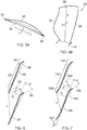
Figure 5A is an illustrative cross section of a fan blade; -
Figure 5B is an illustrative side view of a fan blade; -
Figure 6 is an example of camber lines of two adjacent blades of a fan of a BLI engine; and -
Figure 7 is a further example of camber lines of two adjacent blades of a fan of a BLI engine. - With reference to
Figure 1 , a gas turbine engine is generally indicated at 10, having a principal androtational axis 11. Theengine 10 comprises, in axial flow series, anair intake 12, apropulsive fan 13, anintermediate pressure compressor 14, a high-pressure compressor 15,combustion equipment 16, a high-pressure turbine 17, anintermediate pressure turbine 18, a low-pressure turbine 19 and anexhaust nozzle 20. Anacelle 21 generally surrounds theengine 10 and defines both theintake 12 and theexhaust nozzle 20. - The
gas turbine engine 10 works in the conventional manner so that air entering theintake 12 is accelerated by thefan 13 to produce two air flows: a first air flow into theintermediate pressure compressor 14 and a second air flow which passes through abypass duct 22 to provide propulsive thrust. Theintermediate pressure compressor 14 compresses the air flow directed into it before delivering that air to thehigh pressure compressor 15 where further compression takes place. - The compressed air exhausted from the high-
pressure compressor 15 is directed into thecombustion equipment 16 where it is mixed with fuel and the mixture combusted. The resultant hot combustion products then expand through, and thereby drive the high, intermediate and low-pressure turbines nozzle 20 to provide additional propulsive thrust. The high 17, intermediate 18 and low 19 pressure turbines drive respectively thehigh pressure compressor 15,intermediate pressure compressor 14 andfan 13, each by suitable interconnecting shaft. - Other gas turbine engines to which the present disclosure may be applied may have alternative configurations. By way of example such engines may have an alternative number of interconnecting shafts (e.g. two) and/or an alternative number of compressors and/or turbines. Further the engine may comprise a gearbox provided in the drive train from a turbine to a compressor and/or fan.
- Referring to
Figure 2 , the present disclosure is concerned with a boundary layer ingestion (BLI)engine 24. In this example, the BLI engine is mounted directly to thefuselage 26 and rearward of thewings 28. A BLI engine is understood in the art to be an engine that is mounted in close proximity to the fuselage or wings, such that the engine ingests flow from theboundary layer 30 around the aircraft. This is contrary to a more conventional arrangement (shown in the lower half ofFigure 2 ) where theengine 101 is mounted away from the boundary layer using apylon 102. The BLI engine of the present disclosure is intended for operation at subsonic conditions. - As illustrated in
Figures 3 and 4 , ingestion of theboundary layer 30 means that there is a variation in the magnitude and direction of the velocity of the air entering the inlet of theBLI engine 24. InFigures 3 and 4 , V refers to flow velocity in the engine frame of reference, U refers to the blade peripheral speed, and W refers to flow velocity in the blade frame of reference. - Referring to
Figures 5A and 5B , in the present application, conventional aero-definitions are used. Afan blade 46 includes a leadingedge 34 and atrailing edge 36. Acamber line 40 is a curved line that extends from the leading edge to the trailing edge and is provided mid-way between the gas washed surfaces (i.e. the pressure surface and the suction surface) of the blade. Achord line 42 is a linear line that extends directly from the leading edge to the trailing edge of the blade. A chordal direction C extends directly from the leadingedge 34 to the trailingedge 36, and is in a direction parallel to the chordal line. A spanwise direction S extends from a position proximal a hub of the fan to atip 38 of the fan blade. A thickness direction T is a direction perpendicular to the chordal direction and the spanwise direction. - The BLI engine of the present disclosure includes a fan (indicated at 13 in
Figure 6 ) that includes adisc 44 and a plurality ofblades 46 integrally formed with the disc. For example, theblades 46 anddisc 44 may be machined from solid, or theblades 46 may be welded to thedisc 44. The blades may be blended to the disc using a circular or elliptical fillet. - The inventor of the present application has unexpectedly found that using a disc with integral blades (commonly referred to as a blisk) on a BLI engine can improve engine performance. This goes against the teaching in the art because the person skilled in the art would not consider using a fan having a disc with integrally formed blades because these engines can experience high vibrations during operation, and a disc with integrally formed blades does not offer any mechanical damping. However, the inventor has unexpectedly found that the blades of the fan can be arranged to reduce vibration to an acceptable level to permit a disc with integral blades to be used.
- The advantages of using a fan having a
disc 44 with integrally formedblades 46 include that the structure can be stronger so distortion of the fan can be reduced. Further, there are no surface contacts (compared to the disc-blade interactions on non-integral bladed discs) that can be subject to high stress and wear. - The
blades 46 of the fan can be arranged to reduce aerodynamic loading and to reduce vibration. The arrangement of the blades will now be described in more detail. - Referring to
Figure 6 , thecamber line 48 of two adjacent blades is illustrated. Apassageway 50 is provided between the blades. The passageway may be considered a covered passageway, in that the passageway extends along the region of overlap between the blades. The width of the passageway converges and then diverges. This means that the distance between thecamber lines 48 of the two adjacent blades decreases and then increases along the passageway in a direction of airflow. The distance between the camber lines is measured in a direction perpendicular to the camber lines. The width A1 at the entrance to the passageway is larger than the width A* mid-way along the passageway, and the width A2 at the exit of the passageway is larger than the width A*. In the present example, the width A* is at the transition point between a mid-section 52 of the blade and a trailingedge section 54 of the blade. The convergent-divergent nature of the passageway can prevent any shock waves in the flow exiting the passageway. - The blades include local cambering of the trailing
edge section 54 of the blades, such that the camber lines of the blades curve more in the trailing edge section than in the mid-section. The trailing edge section extends from a point where the increase in curvature of the trailing edge section starts to the trailing edge. An angle e between the chord of the mid-section (i.e. the camber line that would be present if there were no local cambering of the trailing edge section), and thecamber 56 of the trailing edge section at the trailing edge is greater than or equal to 10 degrees. As can be seen, this means thecamber line 48 of the blades is on one side of thechordal line 58, and is spaced a maximum distance from the chordal line at a transition between the mid-section and the trailing edge section. - Referring now to
Figure 7 , alternative blade arrangements may include local cambering of the leading edge. The remaining features of the blade arrangement are substantially similar to the blade arrangement previously described so the features previously described will not be repeated here. In the example shown inFigure 7 , thepassageway 150 between the blades is convergent-divergent as previously described. That is, the width A1 of the passageway at the entrance is greater than the width A* of the passageway mid-way along the passageway at a transition between a mid-section 152 and a trailingedge section 154. Also, the width A2 of the passageway at the exit is greater than the width A* mid-way along the passageway. As can be seen when comparingFigures 6 and 7 , the difference between the widths A1 and A* is greater for the blades illustrated inFigure 7 than inFigure 6 . - The increase in difference in widths A1 and A* is due to local cambering of the leading edge. As can be seen in
Figure 7 , aleading edge section 160 has an increased camber compared to the camber of the mid-section. In the present example, thecamber 162 at the leading edge is less than 10 degrees from the camber of the mid-section at a transition from the leading edge section to the mid-section (i.e. the camber line that would be present if there were no local cambering of the trailing edge section). The camber of the leading edge section is angled from the camber of the mid-section in an opposite direction to thecamber 156 of the trailing edge section. The leading edge section, mid-section and trailing edge section together define acamber line 148 of the blade that defines a substantially S-shape. The S-shape of the camber line means that the camber line extends to one side of thechordal line 164 and then to the opposite side of the chordal line. The maximum distance between the camber line and the chordal line is at the transition points between the leading edge section and the mid-section and the trailing edge section and the mid-section. - Referring again to
Figure 6 , theblades 46 of the fan may have an aspect ratio equal to or between 2.0 and 2.5. Aspect ratio is understood to be the height (measured in a spanwise direction) to chord (i.e. the length of the chordal line) ratio. The blades of the fan may have a thickness (measured in the thickness direction) to chord ratio equal to or between 0.12 and 0.25 at a position adjacent the disc of the fan, and equal to or between 0.02 and 0.04 at a tip of the fan blade. - During operation, the fan tip loading less than 0.3, where fan tip loading is calculated by dH/Utip 2, where dH is the enthalpy rise across the fan (for example the 1-D average enthalpy rise of the flow across the fan at cruise conditions), and Utip is the velocity of the tip, for example at cruise conditions, which may be calculated as the rotational speed multiplied by the tip radius at the leading edge.
- The aircraft boundary layer will induce a change in blade surface pressures every fan revolution. This change results in cyclic loading of the blade which will induce blade vibrations. In the present example, the vibration mode does not significantly change the distance µ indicated in
Figures 6 and 7 . - The described fan arrangements have been found to reduce blade vibratory response associated with boundary layer ingestion and/or other flow velocity distortion into the fan rotor.
- It will be understood that the invention is not limited to the embodiments above-described and various modifications and improvements can be made without departing from the concepts described herein. Except where mutually exclusive, any of the features may be employed separately or in combination with any other features and the disclosure extends to and includes all combinations and subcombinations of one or more features described herein.
Claims (10)
- A boundary layer ingestion engine comprising a fan, the fan comprising a disc and a plurality of blades integrally formed with the disc.
- The engine according to claim 1, wherein a passageway is defined between adjacent blades, and the blades are arranged relative to each other and are cambered such that the width of the passageway between the adjacent blades converges and then diverges from an entrance to an exit of the passageway, with the width being measured perpendicularly to a camber line of the blades.
- The engine according to any one of the previous claims, wherein each blade comprises a mid-section and a trailing edge section adjacent the mid-section and curving from the mid-section, and wherein the camber of a trailing edge of the blade is angled at least 10 degrees from the chord of the mid-section of the blade.
- The engine according to any one of the previous claims, wherein each blade comprises a mid-section and a leading edge section adjacent the mid-section and curving from the mid-section, and wherein the camber of a leading edge of the blade is angled equal to or between 1 and 10 degrees from the chord of the mid-section of the blade.
- The engine according to any one of the previous claims, wherein each blade comprises a mid-section, a trailing edge section adjacent the mid-section, and a leading edge section adjacent the mid-section, and wherein the trailing edge section and the leading edge section are locally cambered and curve from the mid-section in opposite directions.
- The engine according to any one of the previous claims, wherein each blade has a height to chord ratio equal or between 2.0 and 2.5.
- The engine according to any one of the previous claims, wherein at a position adjacent the disc each blade has a thickness to chord ratio equal to or between 0.12 and 0.25.
- The engine according to any one of the previous claims, wherein each blade has a thickness to chord ratio at the tip equal to or between 0.02 and 0.04.
- A gas turbine engine for operation in subsonic conditions comprising a fan having a disc and a plurality of blades arranged around the disc, wherein a leading edge section of each blade is locally cambered in a first direction and a trailing edge section of each blade is locally cambered in a second direction, and wherein the first direction and second direction are such that a camber line of the blade bisects a chordal line of the blade.
- An aircraft comprising a fuselage, wings and a gas turbine engine according to any one of the previous claims, wherein the gas turbine engine is mounted adjacent to the fuselage or wings by a distance such that a boundary layer flow over the fuselage is ingested in the engine.
Applications Claiming Priority (1)
| Application Number | Priority Date | Filing Date | Title |
|---|---|---|---|
| GBGB1704657.4A GB201704657D0 (en) | 2017-03-24 | 2017-03-24 | Gas turbine engine |
Publications (2)
| Publication Number | Publication Date |
|---|---|
| EP3378780A1 true EP3378780A1 (en) | 2018-09-26 |
| EP3378780B1 EP3378780B1 (en) | 2022-04-06 |
Family
ID=58688165
Family Applications (1)
| Application Number | Title | Priority Date | Filing Date |
|---|---|---|---|
| EP18158548.0A Active EP3378780B1 (en) | 2017-03-24 | 2018-02-26 | Boundary layer ingestion engine with integrally bladed fan disk |
Country Status (3)
| Country | Link |
|---|---|
| US (1) | US10711614B2 (en) |
| EP (1) | EP3378780B1 (en) |
| GB (1) | GB201704657D0 (en) |
Cited By (8)
| Publication number | Priority date | Publication date | Assignee | Title |
|---|---|---|---|---|
| EP3653512A1 (en) * | 2018-11-16 | 2020-05-20 | Rolls-Royce plc | Boundary layer ingestion fan system |
| EP3653511A1 (en) * | 2018-11-16 | 2020-05-20 | Rolls-Royce plc | Boundary layer ingestion fan system |
| EP3653509A1 (en) * | 2018-11-16 | 2020-05-20 | Rolls-Royce plc | Boundary layer ingestion fan system |
| EP3653508A1 (en) * | 2018-11-16 | 2020-05-20 | Rolls-Royce plc | Boundary layer ingestion fan system |
| EP3653513A1 (en) * | 2018-11-16 | 2020-05-20 | Rolls-Royce plc | Boundary layer ingestion fan system |
| US11359493B2 (en) | 2020-06-30 | 2022-06-14 | Rolls-Royce Plc | Low speed fan up camber |
| US11364996B2 (en) | 2018-11-16 | 2022-06-21 | Rolls-Royce Plc | Boundary layer ingestion fan system |
| US11414178B2 (en) | 2018-11-16 | 2022-08-16 | Rolls-Royce Plc | Boundary layer ingestion fan system |
Families Citing this family (4)
| Publication number | Priority date | Publication date | Assignee | Title |
|---|---|---|---|---|
| DE102016107656A1 (en) * | 2016-04-25 | 2017-10-26 | Ebm-Papst Mulfingen Gmbh & Co. Kg | Blade edge geometry of a blade of an air conveyor wheel |
| US20190061961A1 (en) * | 2017-08-22 | 2019-02-28 | General Electric Company | Aircraft propulsion system and method |
| FR3076865B1 (en) * | 2018-01-18 | 2020-01-03 | Safran Nacelles | REAR ASSEMBLY OF AN AIRCRAFT TURBOREACTOR NACELLE INCLUDING A SLIDING GRID DRIVE INVERTER |
| US20250319965A1 (en) * | 2024-04-15 | 2025-10-16 | Lockheed Martin Corporation | Low drag airfoil |
Citations (4)
| Publication number | Priority date | Publication date | Assignee | Title |
|---|---|---|---|---|
| EP1712738A2 (en) * | 2005-04-07 | 2006-10-18 | The General Electric Company | Low solidity turbofan |
| US20070243068A1 (en) * | 2005-04-07 | 2007-10-18 | General Electric Company | Tip cambered swept blade |
| US20140169972A1 (en) * | 2012-12-17 | 2014-06-19 | United Technologies Corporation | Fan with integral shroud |
| EP2855847A1 (en) * | 2012-05-31 | 2015-04-08 | SNECMA Services | Fan blade for a turbojet of an aircraft having a cambered profile in the foot sections |
Family Cites Families (5)
| Publication number | Priority date | Publication date | Assignee | Title |
|---|---|---|---|---|
| US5167489A (en) * | 1991-04-15 | 1992-12-01 | General Electric Company | Forward swept rotor blade |
| GB0428368D0 (en) * | 2004-12-24 | 2005-02-02 | Rolls Royce Plc | A composite blade |
| US7497664B2 (en) * | 2005-08-16 | 2009-03-03 | General Electric Company | Methods and apparatus for reducing vibrations induced to airfoils |
| US9476385B2 (en) | 2012-11-12 | 2016-10-25 | The Boeing Company | Rotational annular airscrew with integrated acoustic arrester |
| US9957055B2 (en) | 2015-09-21 | 2018-05-01 | General Electric Company | Aft engine for an aircraft |
-
2017
- 2017-03-24 GB GBGB1704657.4A patent/GB201704657D0/en not_active Ceased
-
2018
- 2018-02-26 EP EP18158548.0A patent/EP3378780B1/en active Active
- 2018-03-23 US US15/933,417 patent/US10711614B2/en active Active
Patent Citations (4)
| Publication number | Priority date | Publication date | Assignee | Title |
|---|---|---|---|---|
| EP1712738A2 (en) * | 2005-04-07 | 2006-10-18 | The General Electric Company | Low solidity turbofan |
| US20070243068A1 (en) * | 2005-04-07 | 2007-10-18 | General Electric Company | Tip cambered swept blade |
| EP2855847A1 (en) * | 2012-05-31 | 2015-04-08 | SNECMA Services | Fan blade for a turbojet of an aircraft having a cambered profile in the foot sections |
| US20140169972A1 (en) * | 2012-12-17 | 2014-06-19 | United Technologies Corporation | Fan with integral shroud |
Cited By (13)
| Publication number | Priority date | Publication date | Assignee | Title |
|---|---|---|---|---|
| US11365634B2 (en) | 2018-11-16 | 2022-06-21 | Rolls-Royce Plc | Boundary layer ingestion fan system |
| EP3653511A1 (en) * | 2018-11-16 | 2020-05-20 | Rolls-Royce plc | Boundary layer ingestion fan system |
| EP3653509A1 (en) * | 2018-11-16 | 2020-05-20 | Rolls-Royce plc | Boundary layer ingestion fan system |
| EP3653508A1 (en) * | 2018-11-16 | 2020-05-20 | Rolls-Royce plc | Boundary layer ingestion fan system |
| EP3653513A1 (en) * | 2018-11-16 | 2020-05-20 | Rolls-Royce plc | Boundary layer ingestion fan system |
| EP3653512A1 (en) * | 2018-11-16 | 2020-05-20 | Rolls-Royce plc | Boundary layer ingestion fan system |
| US11364996B2 (en) | 2018-11-16 | 2022-06-21 | Rolls-Royce Plc | Boundary layer ingestion fan system |
| US11365633B2 (en) | 2018-11-16 | 2022-06-21 | Rolls-Royce Plc | Boundary layer ingestion fan system |
| US11370530B2 (en) | 2018-11-16 | 2022-06-28 | Rolls-Royce Plc | Boundary layer ingestion fan system |
| US11414178B2 (en) | 2018-11-16 | 2022-08-16 | Rolls-Royce Plc | Boundary layer ingestion fan system |
| US11486254B2 (en) | 2018-11-16 | 2022-11-01 | Rolls-Royce Plc | Boundary layer ingestion fan system |
| US11486253B2 (en) | 2018-11-16 | 2022-11-01 | Rolls-Royce Plc | Boundary layer ingestion fan system |
| US11359493B2 (en) | 2020-06-30 | 2022-06-14 | Rolls-Royce Plc | Low speed fan up camber |
Also Published As
| Publication number | Publication date |
|---|---|
| US10711614B2 (en) | 2020-07-14 |
| GB201704657D0 (en) | 2017-05-10 |
| US20180283179A1 (en) | 2018-10-04 |
| EP3378780B1 (en) | 2022-04-06 |
Similar Documents
| Publication | Publication Date | Title |
|---|---|---|
| US10711614B2 (en) | Gas turbine engine | |
| CN108425883B (en) | Gas turbine engine fan blade | |
| US10718216B2 (en) | Airfoil for gas turbine engine | |
| CN107829958B (en) | Aircraft fan with low partial wingspan | |
| US8147207B2 (en) | Compressor blade having a ratio of leading edge sweep to leading edge dihedral in a range of 1:1 to 3:1 along the radially outer portion | |
| CN108425884B (en) | Gas Turbine Engine Fan Blades | |
| US10018050B2 (en) | Turbomachine rotor blade | |
| US7121792B1 (en) | Nozzle vane with two slopes | |
| CN109838307B (en) | Gas turbine engine | |
| US8721287B2 (en) | Compressor impeller blade with variable elliptic connection | |
| JP5177959B2 (en) | Low solidity turbofan | |
| US12320274B2 (en) | Compressor stator with leading edge fillet | |
| US20100232970A1 (en) | Fan rotating blade for turbofan engine | |
| US20080107538A1 (en) | swept turbomachine blade | |
| EP3208467A1 (en) | Compressor rotor for supersonic flutter and/or resonant stress mitigation | |
| EP3392459A1 (en) | Compressor blades | |
| CN110953071A (en) | Air inlet of nacelle | |
| RU2727823C2 (en) | Turbomachine rotor blade, disc with blades, rotor and turbomachine | |
| US20140234112A1 (en) | Rotor blade | |
| CN113272520B (en) | Turbine blade having maximum thickness law with high flutter margin | |
| US11098590B2 (en) | Blade of a turbine engine having a chord law for a high flutter margin | |
| US11753943B2 (en) | Turbomachine blade having a sweep law with high flutter margin | |
| US20200049022A1 (en) | Gas turbine engine mounting arrangement | |
| US11692454B2 (en) | Aircraft engine | |
| CN110700897A (en) | Blade for a gas turbine engine |
Legal Events
| Date | Code | Title | Description |
|---|---|---|---|
| PUAI | Public reference made under article 153(3) epc to a published international application that has entered the european phase |
Free format text: ORIGINAL CODE: 0009012 |
|
| STAA | Information on the status of an ep patent application or granted ep patent |
Free format text: STATUS: THE APPLICATION HAS BEEN PUBLISHED |
|
| AK | Designated contracting states |
Kind code of ref document: A1 Designated state(s): AL AT BE BG CH CY CZ DE DK EE ES FI FR GB GR HR HU IE IS IT LI LT LU LV MC MK MT NL NO PL PT RO RS SE SI SK SM TR |
|
| AX | Request for extension of the european patent |
Extension state: BA ME |
|
| STAA | Information on the status of an ep patent application or granted ep patent |
Free format text: STATUS: REQUEST FOR EXAMINATION WAS MADE |
|
| 17P | Request for examination filed |
Effective date: 20190319 |
|
| RBV | Designated contracting states (corrected) |
Designated state(s): AL AT BE BG CH CY CZ DE DK EE ES FI FR GB GR HR HU IE IS IT LI LT LU LV MC MK MT NL NO PL PT RO RS SE SI SK SM TR |
|
| RAP1 | Party data changed (applicant data changed or rights of an application transferred) |
Owner name: ROLLS-ROYCE PLC |
|
| RIC1 | Information provided on ipc code assigned before grant |
Ipc: F04D 29/32 20060101ALI20211027BHEP Ipc: F01D 5/16 20060101ALI20211027BHEP Ipc: F01D 5/34 20060101ALI20211027BHEP Ipc: F01D 5/14 20060101ALI20211027BHEP Ipc: B64D 29/06 20060101AFI20211027BHEP |
|
| GRAP | Despatch of communication of intention to grant a patent |
Free format text: ORIGINAL CODE: EPIDOSNIGR1 |
|
| STAA | Information on the status of an ep patent application or granted ep patent |
Free format text: STATUS: GRANT OF PATENT IS INTENDED |
|
| GRAJ | Information related to disapproval of communication of intention to grant by the applicant or resumption of examination proceedings by the epo deleted |
Free format text: ORIGINAL CODE: EPIDOSDIGR1 |
|
| STAA | Information on the status of an ep patent application or granted ep patent |
Free format text: STATUS: REQUEST FOR EXAMINATION WAS MADE |
|
| INTG | Intention to grant announced |
Effective date: 20211216 |
|
| INTC | Intention to grant announced (deleted) | ||
| GRAP | Despatch of communication of intention to grant a patent |
Free format text: ORIGINAL CODE: EPIDOSNIGR1 |
|
| STAA | Information on the status of an ep patent application or granted ep patent |
Free format text: STATUS: GRANT OF PATENT IS INTENDED |
|
| GRAS | Grant fee paid |
Free format text: ORIGINAL CODE: EPIDOSNIGR3 |
|
| GRAA | (expected) grant |
Free format text: ORIGINAL CODE: 0009210 |
|
| STAA | Information on the status of an ep patent application or granted ep patent |
Free format text: STATUS: THE PATENT HAS BEEN GRANTED |
|
| INTG | Intention to grant announced |
Effective date: 20220209 |
|
| AK | Designated contracting states |
Kind code of ref document: B1 Designated state(s): AL AT BE BG CH CY CZ DE DK EE ES FI FR GB GR HR HU IE IS IT LI LT LU LV MC MK MT NL NO PL PT RO RS SE SI SK SM TR |
|
| REG | Reference to a national code |
Ref country code: GB Ref legal event code: FG4D |
|
| REG | Reference to a national code |
Ref country code: CH Ref legal event code: EP |
|
| REG | Reference to a national code |
Ref country code: AT Ref legal event code: REF Ref document number: 1481126 Country of ref document: AT Kind code of ref document: T Effective date: 20220415 |
|
| REG | Reference to a national code |
Ref country code: IE Ref legal event code: FG4D |
|
| REG | Reference to a national code |
Ref country code: DE Ref legal event code: R096 Ref document number: 602018033216 Country of ref document: DE |
|
| REG | Reference to a national code |
Ref country code: LT Ref legal event code: MG9D |
|
| REG | Reference to a national code |
Ref country code: NL Ref legal event code: MP Effective date: 20220406 |
|
| REG | Reference to a national code |
Ref country code: AT Ref legal event code: MK05 Ref document number: 1481126 Country of ref document: AT Kind code of ref document: T Effective date: 20220406 |
|
| PG25 | Lapsed in a contracting state [announced via postgrant information from national office to epo] |
Ref country code: NL Free format text: LAPSE BECAUSE OF FAILURE TO SUBMIT A TRANSLATION OF THE DESCRIPTION OR TO PAY THE FEE WITHIN THE PRESCRIBED TIME-LIMIT Effective date: 20220406 |
|
| PG25 | Lapsed in a contracting state [announced via postgrant information from national office to epo] |
Ref country code: SE Free format text: LAPSE BECAUSE OF FAILURE TO SUBMIT A TRANSLATION OF THE DESCRIPTION OR TO PAY THE FEE WITHIN THE PRESCRIBED TIME-LIMIT Effective date: 20220406 Ref country code: PT Free format text: LAPSE BECAUSE OF FAILURE TO SUBMIT A TRANSLATION OF THE DESCRIPTION OR TO PAY THE FEE WITHIN THE PRESCRIBED TIME-LIMIT Effective date: 20220808 Ref country code: NO Free format text: LAPSE BECAUSE OF FAILURE TO SUBMIT A TRANSLATION OF THE DESCRIPTION OR TO PAY THE FEE WITHIN THE PRESCRIBED TIME-LIMIT Effective date: 20220706 Ref country code: LT Free format text: LAPSE BECAUSE OF FAILURE TO SUBMIT A TRANSLATION OF THE DESCRIPTION OR TO PAY THE FEE WITHIN THE PRESCRIBED TIME-LIMIT Effective date: 20220406 Ref country code: HR Free format text: LAPSE BECAUSE OF FAILURE TO SUBMIT A TRANSLATION OF THE DESCRIPTION OR TO PAY THE FEE WITHIN THE PRESCRIBED TIME-LIMIT Effective date: 20220406 Ref country code: GR Free format text: LAPSE BECAUSE OF FAILURE TO SUBMIT A TRANSLATION OF THE DESCRIPTION OR TO PAY THE FEE WITHIN THE PRESCRIBED TIME-LIMIT Effective date: 20220707 Ref country code: FI Free format text: LAPSE BECAUSE OF FAILURE TO SUBMIT A TRANSLATION OF THE DESCRIPTION OR TO PAY THE FEE WITHIN THE PRESCRIBED TIME-LIMIT Effective date: 20220406 Ref country code: ES Free format text: LAPSE BECAUSE OF FAILURE TO SUBMIT A TRANSLATION OF THE DESCRIPTION OR TO PAY THE FEE WITHIN THE PRESCRIBED TIME-LIMIT Effective date: 20220406 Ref country code: BG Free format text: LAPSE BECAUSE OF FAILURE TO SUBMIT A TRANSLATION OF THE DESCRIPTION OR TO PAY THE FEE WITHIN THE PRESCRIBED TIME-LIMIT Effective date: 20220706 Ref country code: AT Free format text: LAPSE BECAUSE OF FAILURE TO SUBMIT A TRANSLATION OF THE DESCRIPTION OR TO PAY THE FEE WITHIN THE PRESCRIBED TIME-LIMIT Effective date: 20220406 |
|
| PG25 | Lapsed in a contracting state [announced via postgrant information from national office to epo] |
Ref country code: RS Free format text: LAPSE BECAUSE OF FAILURE TO SUBMIT A TRANSLATION OF THE DESCRIPTION OR TO PAY THE FEE WITHIN THE PRESCRIBED TIME-LIMIT Effective date: 20220406 Ref country code: PL Free format text: LAPSE BECAUSE OF FAILURE TO SUBMIT A TRANSLATION OF THE DESCRIPTION OR TO PAY THE FEE WITHIN THE PRESCRIBED TIME-LIMIT Effective date: 20220406 Ref country code: LV Free format text: LAPSE BECAUSE OF FAILURE TO SUBMIT A TRANSLATION OF THE DESCRIPTION OR TO PAY THE FEE WITHIN THE PRESCRIBED TIME-LIMIT Effective date: 20220406 Ref country code: IS Free format text: LAPSE BECAUSE OF FAILURE TO SUBMIT A TRANSLATION OF THE DESCRIPTION OR TO PAY THE FEE WITHIN THE PRESCRIBED TIME-LIMIT Effective date: 20220806 |
|
| REG | Reference to a national code |
Ref country code: DE Ref legal event code: R097 Ref document number: 602018033216 Country of ref document: DE |
|
| PG25 | Lapsed in a contracting state [announced via postgrant information from national office to epo] |
Ref country code: SM Free format text: LAPSE BECAUSE OF FAILURE TO SUBMIT A TRANSLATION OF THE DESCRIPTION OR TO PAY THE FEE WITHIN THE PRESCRIBED TIME-LIMIT Effective date: 20220406 Ref country code: SK Free format text: LAPSE BECAUSE OF FAILURE TO SUBMIT A TRANSLATION OF THE DESCRIPTION OR TO PAY THE FEE WITHIN THE PRESCRIBED TIME-LIMIT Effective date: 20220406 Ref country code: RO Free format text: LAPSE BECAUSE OF FAILURE TO SUBMIT A TRANSLATION OF THE DESCRIPTION OR TO PAY THE FEE WITHIN THE PRESCRIBED TIME-LIMIT Effective date: 20220406 Ref country code: EE Free format text: LAPSE BECAUSE OF FAILURE TO SUBMIT A TRANSLATION OF THE DESCRIPTION OR TO PAY THE FEE WITHIN THE PRESCRIBED TIME-LIMIT Effective date: 20220406 Ref country code: DK Free format text: LAPSE BECAUSE OF FAILURE TO SUBMIT A TRANSLATION OF THE DESCRIPTION OR TO PAY THE FEE WITHIN THE PRESCRIBED TIME-LIMIT Effective date: 20220406 Ref country code: CZ Free format text: LAPSE BECAUSE OF FAILURE TO SUBMIT A TRANSLATION OF THE DESCRIPTION OR TO PAY THE FEE WITHIN THE PRESCRIBED TIME-LIMIT Effective date: 20220406 |
|
| PLBE | No opposition filed within time limit |
Free format text: ORIGINAL CODE: 0009261 |
|
| STAA | Information on the status of an ep patent application or granted ep patent |
Free format text: STATUS: NO OPPOSITION FILED WITHIN TIME LIMIT |
|
| 26N | No opposition filed |
Effective date: 20230110 |
|
| PG25 | Lapsed in a contracting state [announced via postgrant information from national office to epo] |
Ref country code: AL Free format text: LAPSE BECAUSE OF FAILURE TO SUBMIT A TRANSLATION OF THE DESCRIPTION OR TO PAY THE FEE WITHIN THE PRESCRIBED TIME-LIMIT Effective date: 20220406 |
|
| PG25 | Lapsed in a contracting state [announced via postgrant information from national office to epo] |
Ref country code: SI Free format text: LAPSE BECAUSE OF FAILURE TO SUBMIT A TRANSLATION OF THE DESCRIPTION OR TO PAY THE FEE WITHIN THE PRESCRIBED TIME-LIMIT Effective date: 20220406 |
|
| P01 | Opt-out of the competence of the unified patent court (upc) registered |
Effective date: 20230528 |
|
| PG25 | Lapsed in a contracting state [announced via postgrant information from national office to epo] |
Ref country code: MC Free format text: LAPSE BECAUSE OF FAILURE TO SUBMIT A TRANSLATION OF THE DESCRIPTION OR TO PAY THE FEE WITHIN THE PRESCRIBED TIME-LIMIT Effective date: 20220406 |
|
| REG | Reference to a national code |
Ref country code: CH Ref legal event code: PL |
|
| REG | Reference to a national code |
Ref country code: BE Ref legal event code: MM Effective date: 20230228 |
|
| PG25 | Lapsed in a contracting state [announced via postgrant information from national office to epo] |
Ref country code: LU Free format text: LAPSE BECAUSE OF NON-PAYMENT OF DUE FEES Effective date: 20230226 Ref country code: LI Free format text: LAPSE BECAUSE OF NON-PAYMENT OF DUE FEES Effective date: 20230228 Ref country code: CH Free format text: LAPSE BECAUSE OF NON-PAYMENT OF DUE FEES Effective date: 20230228 |
|
| REG | Reference to a national code |
Ref country code: IE Ref legal event code: MM4A |
|
| PG25 | Lapsed in a contracting state [announced via postgrant information from national office to epo] |
Ref country code: IT Free format text: LAPSE BECAUSE OF FAILURE TO SUBMIT A TRANSLATION OF THE DESCRIPTION OR TO PAY THE FEE WITHIN THE PRESCRIBED TIME-LIMIT Effective date: 20220406 Ref country code: IE Free format text: LAPSE BECAUSE OF NON-PAYMENT OF DUE FEES Effective date: 20230226 |
|
| PG25 | Lapsed in a contracting state [announced via postgrant information from national office to epo] |
Ref country code: BE Free format text: LAPSE BECAUSE OF NON-PAYMENT OF DUE FEES Effective date: 20230228 |
|
| PG25 | Lapsed in a contracting state [announced via postgrant information from national office to epo] |
Ref country code: BG Free format text: LAPSE BECAUSE OF FAILURE TO SUBMIT A TRANSLATION OF THE DESCRIPTION OR TO PAY THE FEE WITHIN THE PRESCRIBED TIME-LIMIT Effective date: 20220406 |
|
| PG25 | Lapsed in a contracting state [announced via postgrant information from national office to epo] |
Ref country code: BG Free format text: LAPSE BECAUSE OF FAILURE TO SUBMIT A TRANSLATION OF THE DESCRIPTION OR TO PAY THE FEE WITHIN THE PRESCRIBED TIME-LIMIT Effective date: 20220406 |
|
| PGFP | Annual fee paid to national office [announced via postgrant information from national office to epo] |
Ref country code: DE Payment date: 20250226 Year of fee payment: 8 |
|
| PGFP | Annual fee paid to national office [announced via postgrant information from national office to epo] |
Ref country code: FR Payment date: 20250224 Year of fee payment: 8 |
|
| PGFP | Annual fee paid to national office [announced via postgrant information from national office to epo] |
Ref country code: GB Payment date: 20250218 Year of fee payment: 8 |
|
| PG25 | Lapsed in a contracting state [announced via postgrant information from national office to epo] |
Ref country code: CY Free format text: LAPSE BECAUSE OF FAILURE TO SUBMIT A TRANSLATION OF THE DESCRIPTION OR TO PAY THE FEE WITHIN THE PRESCRIBED TIME-LIMIT; INVALID AB INITIO Effective date: 20180226 |
|
| PG25 | Lapsed in a contracting state [announced via postgrant information from national office to epo] |
Ref country code: HU Free format text: LAPSE BECAUSE OF FAILURE TO SUBMIT A TRANSLATION OF THE DESCRIPTION OR TO PAY THE FEE WITHIN THE PRESCRIBED TIME-LIMIT; INVALID AB INITIO Effective date: 20180226 |
|
| PG25 | Lapsed in a contracting state [announced via postgrant information from national office to epo] |
Ref country code: TR Free format text: LAPSE BECAUSE OF FAILURE TO SUBMIT A TRANSLATION OF THE DESCRIPTION OR TO PAY THE FEE WITHIN THE PRESCRIBED TIME-LIMIT Effective date: 20220406 |